EP1981418B1 - Fixationssystem für knochen mit einem sensor- und telemetriesystem - Google Patents
Fixationssystem für knochen mit einem sensor- und telemetriesystem Download PDFInfo
- Publication number
- EP1981418B1 EP1981418B1 EP07703148.2A EP07703148A EP1981418B1 EP 1981418 B1 EP1981418 B1 EP 1981418B1 EP 07703148 A EP07703148 A EP 07703148A EP 1981418 B1 EP1981418 B1 EP 1981418B1
- Authority
- EP
- European Patent Office
- Prior art keywords
- fixation system
- sensor
- separate plate
- connection
- groove
- Prior art date
- Legal status (The legal status is an assumption and is not a legal conclusion. Google has not performed a legal analysis and makes no representation as to the accuracy of the status listed.)
- Not-in-force
Links
- 210000000988 bone and bone Anatomy 0.000 title claims description 37
- 239000002775 capsule Substances 0.000 claims description 15
- 239000000463 material Substances 0.000 claims description 6
- 230000000295 complement effect Effects 0.000 claims description 5
- 230000006698 induction Effects 0.000 claims description 3
- 229910052751 metal Inorganic materials 0.000 claims description 3
- 239000002184 metal Substances 0.000 claims description 3
- 239000003990 capacitor Substances 0.000 claims description 2
- 238000003780 insertion Methods 0.000 claims description 2
- 230000037431 insertion Effects 0.000 claims description 2
- 206010033675 panniculitis Diseases 0.000 claims 1
- 210000004304 subcutaneous tissue Anatomy 0.000 claims 1
- 230000035876 healing Effects 0.000 description 9
- 230000005540 biological transmission Effects 0.000 description 7
- 238000003860 storage Methods 0.000 description 7
- RTAQQCXQSZGOHL-UHFFFAOYSA-N Titanium Chemical compound [Ti] RTAQQCXQSZGOHL-UHFFFAOYSA-N 0.000 description 3
- 230000008054 signal transmission Effects 0.000 description 3
- 239000010936 titanium Substances 0.000 description 3
- 229910052719 titanium Inorganic materials 0.000 description 3
- 229910001069 Ti alloy Inorganic materials 0.000 description 2
- 238000003384 imaging method Methods 0.000 description 2
- 238000004519 manufacturing process Methods 0.000 description 2
- 206010017577 Gait disturbance Diseases 0.000 description 1
- 238000010521 absorption reaction Methods 0.000 description 1
- 238000004026 adhesive bonding Methods 0.000 description 1
- 238000004891 communication Methods 0.000 description 1
- 238000002591 computed tomography Methods 0.000 description 1
- 230000003247 decreasing effect Effects 0.000 description 1
- 230000002950 deficient Effects 0.000 description 1
- 238000009826 distribution Methods 0.000 description 1
- 238000005538 encapsulation Methods 0.000 description 1
- 238000005516 engineering process Methods 0.000 description 1
- 230000002349 favourable effect Effects 0.000 description 1
- 239000011888 foil Substances 0.000 description 1
- 239000012634 fragment Substances 0.000 description 1
- 210000004394 hip joint Anatomy 0.000 description 1
- 208000015181 infectious disease Diseases 0.000 description 1
- 238000002595 magnetic resonance imaging Methods 0.000 description 1
- 238000005259 measurement Methods 0.000 description 1
- 238000000034 method Methods 0.000 description 1
- 238000003825 pressing Methods 0.000 description 1
- 238000012545 processing Methods 0.000 description 1
- 210000004872 soft tissue Anatomy 0.000 description 1
- 239000000126 substance Substances 0.000 description 1
- 238000002560 therapeutic procedure Methods 0.000 description 1
- 210000001519 tissue Anatomy 0.000 description 1
- 238000012546 transfer Methods 0.000 description 1
- 238000003466 welding Methods 0.000 description 1
Images


Classifications
-
- A—HUMAN NECESSITIES
- A61—MEDICAL OR VETERINARY SCIENCE; HYGIENE
- A61B—DIAGNOSIS; SURGERY; IDENTIFICATION
- A61B17/00—Surgical instruments, devices or methods
- A61B17/56—Surgical instruments or methods for treatment of bones or joints; Devices specially adapted therefor
- A61B17/58—Surgical instruments or methods for treatment of bones or joints; Devices specially adapted therefor for osteosynthesis, e.g. bone plates, screws or setting implements
- A61B17/68—Internal fixation devices, including fasteners and spinal fixators, even if a part thereof projects from the skin
- A61B17/80—Cortical plates, i.e. bone plates; Instruments for holding or positioning cortical plates, or for compressing bones attached to cortical plates
-
- A—HUMAN NECESSITIES
- A61—MEDICAL OR VETERINARY SCIENCE; HYGIENE
- A61B—DIAGNOSIS; SURGERY; IDENTIFICATION
- A61B17/00—Surgical instruments, devices or methods
- A61B17/56—Surgical instruments or methods for treatment of bones or joints; Devices specially adapted therefor
- A61B17/58—Surgical instruments or methods for treatment of bones or joints; Devices specially adapted therefor for osteosynthesis, e.g. bone plates, screws or setting implements
- A61B17/60—Surgical instruments or methods for treatment of bones or joints; Devices specially adapted therefor for osteosynthesis, e.g. bone plates, screws or setting implements for external osteosynthesis, e.g. distractors, contractors
-
- A—HUMAN NECESSITIES
- A61—MEDICAL OR VETERINARY SCIENCE; HYGIENE
- A61B—DIAGNOSIS; SURGERY; IDENTIFICATION
- A61B17/00—Surgical instruments, devices or methods
- A61B17/56—Surgical instruments or methods for treatment of bones or joints; Devices specially adapted therefor
- A61B17/58—Surgical instruments or methods for treatment of bones or joints; Devices specially adapted therefor for osteosynthesis, e.g. bone plates, screws or setting implements
- A61B17/68—Internal fixation devices, including fasteners and spinal fixators, even if a part thereof projects from the skin
- A61B17/72—Intramedullary devices, e.g. pins or nails
-
- A—HUMAN NECESSITIES
- A61—MEDICAL OR VETERINARY SCIENCE; HYGIENE
- A61B—DIAGNOSIS; SURGERY; IDENTIFICATION
- A61B5/00—Measuring for diagnostic purposes; Identification of persons
- A61B5/0002—Remote monitoring of patients using telemetry, e.g. transmission of vital signals via a communication network
- A61B5/0031—Implanted circuitry
-
- A—HUMAN NECESSITIES
- A61—MEDICAL OR VETERINARY SCIENCE; HYGIENE
- A61B—DIAGNOSIS; SURGERY; IDENTIFICATION
- A61B5/00—Measuring for diagnostic purposes; Identification of persons
- A61B5/45—For evaluating or diagnosing the musculoskeletal system or teeth
- A61B5/4504—Bones
-
- A—HUMAN NECESSITIES
- A61—MEDICAL OR VETERINARY SCIENCE; HYGIENE
- A61B—DIAGNOSIS; SURGERY; IDENTIFICATION
- A61B17/00—Surgical instruments, devices or methods
- A61B2017/00681—Aspects not otherwise provided for
- A61B2017/00734—Aspects not otherwise provided for battery operated
-
- A—HUMAN NECESSITIES
- A61—MEDICAL OR VETERINARY SCIENCE; HYGIENE
- A61B—DIAGNOSIS; SURGERY; IDENTIFICATION
- A61B90/00—Instruments, implements or accessories specially adapted for surgery or diagnosis and not covered by any of the groups A61B1/00 - A61B50/00, e.g. for luxation treatment or for protecting wound edges
- A61B90/06—Measuring instruments not otherwise provided for
- A61B2090/064—Measuring instruments not otherwise provided for for measuring force, pressure or mechanical tension
-
- A—HUMAN NECESSITIES
- A61—MEDICAL OR VETERINARY SCIENCE; HYGIENE
- A61B—DIAGNOSIS; SURGERY; IDENTIFICATION
- A61B2562/00—Details of sensors; Constructional details of sensor housings or probes; Accessories for sensors
- A61B2562/02—Details of sensors specially adapted for in-vivo measurements
- A61B2562/0261—Strain gauges
Definitions
- the invention relates to a bone fixation system with a sensor and telemetry system.
- connection carrier bridges the fracture and is connected to the bone fragments via at least one bone screw.
- the connection carrier is for example a bone plate, an intramedullary nail or a fixator externally. It is advantageous if the bone screw is permanently locked in the connection carrier angle stable.
- connection carrier particularly advantageous is a free selectability of the screw direction before permanently locking stable locking of the bone screw in the connection carrier.
- the angularly stable connection of bone screw and connection carrier leads to a gain in stability of the entire assembly due to the special nature of the transmission of forces and loads. This transmission is characterized by the areal distribution of forces. Furthermore, biomechanical and clinical results show more favorable healing courses.
- imaging techniques are primarily X-ray examinations, magnetic resonance imaging and computed tomography. It is known that these imaging methods in their Meaningfulness the real healing process several weeks behind limping.
- Bone fixation systems have previously been combined with sensor systems. This strain gauges were used, which were connected to cable, which were led through the skin to the outside. In particular, the infection problem has led to such systems were used only in exceptional cases.
- sensor systems have been in clinical use, which work together with a telemetry system, which wirelessly transmits the measured values obtained by the sensor system in the body to the outside.
- the production of these systems is difficult, expensive and expensive. Only in individual cases, therefore, have these systems - eg in the area of the spine or the hip joint - used to answer questions about the ability to exercise, the forces and after healing.
- Sensor and telemetry systems are connected by gluing to the fixation system.
- the US-A-6034296 and the WO-A-2005074821 disclose bone fixation systems having a connector support, at least one bone screw insertable into a through hole of the connector support, and a sensor and telemetry system disposed on a separate plate connectable to the connector support.
- the object of the invention is to provide a fixation system for bones with a sensor and telemetry system in which the power flow takes place via the sensor system.
- fixation system with a sensor and telemetry system having the features of claim 1.
- Advantageous embodiments of the fixation system with the sensor and telemetry system are specified in the subclaims.
- the fixation system for bone has a connection carrier, at least one in a through hole of the connection carrier usable bone screw and a sensor and telemetry system, wherein the sensor and telemetry system is arranged on a separate plate which is connectable to the connection carrier, characterized in that connection carrier and separate plate means for forming at least one tongue-and-groove connection between connection carrier and Plate.
- the fixation system in the fixation system according to the invention, the sensor and telemetry system is arranged on a separate plate which is connectable to the connection carrier, the surgeon can decide at the end of the operation, whether the fixation system must be equipped with the sensor and telemetry system. If this is not required, it omits the sensor and telemetry system and only uses the fixation system. This saves effort and costs. The surgeon is made easier to decide on the use of this combined system. However, if the patient needs the combined system, the surgeon can simply connect the plate to the sensor and telemetry system with the fixation system.
- the invention can be used in particular for fixation systems in which at least one bone screw has a permanently angularly stable connection with the carrier. It can be used, for example, for fixation systems in which at least one bone screw is seated in a defined angular orientation in the through hole.
- the through hole may guide the bone screw in a defined angular orientation or with a be executed predetermined thread into which the bone screw is screwed exclusively in a defined orientation.
- bone screw and through hole have means for angularly stable connection in selectable angular orientation.
- These devices are according to one embodiment means for forming a thread between the bone screw and through hole. This makes it possible to permanently connect a screw which can be inserted into the connection carrier in variable angle orientations with the connection carrier in a manner that is stable in terms of angular stability.
- the means for forming a thread include, for example, a thread on the bone screw and a threadless through hole into which the bone screw at a selectable angle to form a female thread is screwed.
- the materials of the bone screw and the inner wall of the through hole or of the connection carrier have different degrees of hardness.
- pure titanium is used for the bone screw and a titanium alloy for the connection carrier or vice versa.
- Other possible embodiments of the device for forming a thread are in the DE 43 43 117 C2 described.
- the invention enables the use of different sensor systems.
- the sensor system measures, for example, chemical parameters or the temperature or the fixation system loading forces or the deformation of the fixation system.
- the sensor system comprises a strain gauge (DMS).
- DMS strain gauge
- the sensor system comprises a sensor for measuring deformations or forces
- the sensor system is mounted on the separate plate and the separate plate on the connection carrier, that the power flow takes place via the connection carrier and the sensor system, so that the in the course of healing, decreasing deformations or forces are measured and transmitted telemetrically.
- the sensor system for measuring the deformations or forces is fixedly connected to the separate plate.
- the separate plate has according to one embodiment means for positive and / or non-positive and / or cohesive connection of connecting carrier and plate.
- the means for connecting are arranged according to an embodiment on different sides of the sensor system, so that the power flow between the means for connection via the sensor system takes place.
- the tongue and groove connection in particular allows a positive connection between the connection carrier and plate.
- a frictional connection is possible by the spring pressed into the groove becomes.
- it can also lead to a cohesive connection, especially if by combining suitable materials for spring and groove welding takes place during the pressing of the spring in the groove. This is the case, for example, in the choice of a titanium alloy for the spring and of pure titanium for the groove or vice versa, since the materials have different degrees of hardness.
- the connection carrier has at least one groove and the plate at least one complementary to the groove spring for insertion into the groove.
- a plurality of tongue and groove connections are arranged on different sides of the sensor system, so that the power flow takes place via the sensor system.
- the groove is circular or oval and the spring is shaped complementary to the groove and the sensor system is arranged within the closed curve defined by the tongue and groove connection. In this single tongue and groove connection, there is also a power flow through the sensor system.
- the plate is circular or oval, wherein the shape of the plate preferably corresponds to the shape of the tongue and groove joint.
- the groove and the spring are conical.
- the groove tapers towards its bottom and / or the spring tapers towards its free end. This makes it possible to press the spring with gradual force entry into the groove and thereby produce a particularly intimate connection between the plate and connection carrier.
- the plate is made of a harder material than the connecting carrier or vice versa, so that during manufacture of the tongue and groove connection, a particularly intimate connection between the plate and the connecting carrier takes place by material deformation. This ensures that the transmission of forces is permanently uniform.
- the tongue and groove connection is e.g. designed as a snap connection or additional snap elements for snapping plate and connection carrier are added to the tongue and groove connection.
- at least one screw connection for connecting plate and connection carrier is present.
- the screw connection is e.g. between the circumference of a circular spring and a circular groove present.
- the screw connection comprises a screw which can be screwed through a through hole of the plate into a threaded bore of the connection carrier.
- the plate can be connected to the connection carrier by means of at least two diametrically opposite screw connections. This is e.g. advantageous in an annular or oval tongue and groove connection between the plate and the connection carrier or a correspondingly shaped plate.
- connection between the sensor system and the plate is achieved by jamming, setting or otherwise. Further, the invention incorporates embodiments in which various types of connection are combined.
- the senor and / or telemetry system is arranged at least partially below the plate in an area enclosed by the tongue-and-groove or screw connection. In this arrangement, the sensor and / or telemetry system is at least partially encapsulated between the connection carrier and the plate. According to one embodiment, the sensor and / or telemetry system is arranged at least partially in a capsule arranged on the upper side of the plate.
- the capsule is made of metal (e.g., titanium) and / or plastic. It is possible to make the encapsulation by a metal foil.
- the metallic capsule has a window through which the telemetry signal can be transmitted to the outside.
- the senor and telemetry system has an antenna.
- the antenna favors wireless transmission of the signals to the outside.
- the partial absorption of the signal by the soft tissue sheath can be bypassed.
- a storage and telemetry unit which can be placed under the skin and has a receiver antenna which can be placed in the vicinity of the sensor and telemetry system is provided.
- a receiver antenna which can be placed in the vicinity of the sensor and telemetry system.
- the sensor and telemetry system has an antenna for wireless transmission of signals to the receiver antenna.
- the sensor and telemetry system and / or the storage and telemetry unit has a power supply by induction and / or by at least one battery system and / or by at least one battery system.
- Induction makes it possible to get energy from the outside, which is needed to make measurements.
- This can also be a charge of capacitors and / or batteries and / or batteries.
- the signals obtained from the sensor and telemetry system may be collected in an external data store that communicates with known data communication systems and / or data processing systems.
- the sensor and telemetry system mountable to a bone fixation system during the most convenient operation, allows for continuous data acquisition and wireless data transmission using commercially available memory technologies.
- the system takes into account economic aspects and allows use if the indication is proven.
- a multidirectionally blockable bone screw 3 is inserted in a through hole 1 of a connection carrier 2 in the form of a bone plate.
- the bone screw 3 can be screwed to a bone, wherein a thread in the vicinity of the screw head 4, a thread is formed in the connection carrier 2.
- a separate plate 5 is arranged with a strain gauge 6 on the connection carrier 2.
- the separate plate 5 is connected by means of further screws 7, which are screwed into threaded holes 8 of the connecting carrier 2, with the connecting carrier 2.
- connection carrier 2 has an oval in plan view and in cross section conical groove 9, in which a complementary spring 10 engages with the separate plate 5.
- the separate plate 5 is again by means of screws 7 which pass through the holes of the separate plate 5 and engage in threaded holes 8 of the connection carrier 2, screwed to the connection carrier 2.
- the separate plate 5 has an oval shaped spring 10 with a conical cross section.
- the spring 10 is einfalzbar in a complementary groove 9 of the connecting carrier 2, as in Fig. 4 shown.
- the separate plate 5 is fixed by means of the screws 7, which pass through the holes 11 of the separate plate 5 and are screwed into the threaded holes 8 of the connecting carrier 2 '.
- the sensor and telemetry system 6 is arranged inside a capsule 12 on the upper side of the separate plate 5.
- the separate plate 5 is applied as a flat, partially hollow screw inside. It has the sensor and telemetry unit 6 on the inside.
- the sensor and telemetry system 6 can also be applied externally and is in this case surrounded by a capsule 12.
- the screwing of this screw-in separate plate is facilitated by a hexagonal recess 17 on the outer surface.
- the separate plate 5 has a sensor and telemetry system 6 with a capsule 12, wherein the capsule 12 has a transmitting antenna 13 led out to ensure a facilitated wireless signal transmission.
- the sensor and telemetry system 6 is arranged within a capsule 12 on the separate plate 5.
- the capsule 12 has a window 14 so that signals from the sensor and telemetry system 6 can escape from the capsule 12.
- Fig. 8 is the separate plate 5 with the window 14 another, for example, under the skin, memory and telemetry unit 16 associated with a receiver antenna 15.
- the storage and telemetry unit 16 is located under the skin 18 and the receiver antenna 15 is located near the window 14 so that wireless signal transmission through the window 14 and / or the transmitting antenna 13 to the receiver antenna 15 can occur.
- Energy can be inductively supplied to the storage and telemetry unit 16 from the outside or the storage and telemetry unit is provided with a battery whose storage capacity is sufficient for the duration of the therapy.
Landscapes
- Health & Medical Sciences (AREA)
- Life Sciences & Earth Sciences (AREA)
- Orthopedic Medicine & Surgery (AREA)
- Surgery (AREA)
- Engineering & Computer Science (AREA)
- General Health & Medical Sciences (AREA)
- Veterinary Medicine (AREA)
- Biomedical Technology (AREA)
- Heart & Thoracic Surgery (AREA)
- Medical Informatics (AREA)
- Molecular Biology (AREA)
- Animal Behavior & Ethology (AREA)
- Public Health (AREA)
- Nuclear Medicine, Radiotherapy & Molecular Imaging (AREA)
- Neurology (AREA)
- Physics & Mathematics (AREA)
- Biophysics (AREA)
- Pathology (AREA)
- Computer Networks & Wireless Communication (AREA)
- Dentistry (AREA)
- Oral & Maxillofacial Surgery (AREA)
- Rheumatology (AREA)
- Measuring And Recording Apparatus For Diagnosis (AREA)
- Surgical Instruments (AREA)
- Prostheses (AREA)
Description
- Die Erfindung betrifft ein Fixationssystem für Knochen mit einem Sensor- und Telemetriesystem.
- Fixationssysteme werden in der Osteosynthese verwendet, wobei der Verbindungsträger den Bruch überbrückt und über mindestens eine Knochenschraube mit den Knochenfragmenten verbunden wird. Der Verbindungsträger ist beispielsweise eine Knochenplatte, ein Marknagel oder ein Fixateur extern. Dabei ist es vorteilhaft, wenn die Knochenschraube in dem Verbindungsträger dauerhaft winkelstabil verblockt ist.
- Besonders vorteilhaft ist eine freie Wählbarkeit der Schraubenrichtung vor der dauerhaft winkelstabilen Verblockung der Knochenschraube im Verbindungsträger. Die winkelstabile Verbindung von Knochenschraube und Verbindungsträger führt zu einem Stabilitätsgewinn der gesamten Montage durch die besondere Art der Übertragung von Kräften und Lasten. Diese Übertragung ist durch die flächenhafte Kraftverteilung charakterisiert. Ferner zeigen biomechanische und klinische Ergebnisse günstigere Heilungsverläufe.
- Die Kontrolle der Heilungsvorgänge bei der Osteosynthese ist durch sogenannte bildgebende Verfahren möglich. Es handelt sich hierbei in erster Linie um Röntgenuntersuchungen, Kernspintomographie und Computertomographie. Es ist bekannt, daß diese bildgebenden Verfahren in ihrer Aussagefähigkeit dem wirklichen Heilungsprozeß mehrere Wochen hinterher hinken.
- Erforderlich ist, die Fähigkeit des heilenden Gewebes im Hinblick auf die Übertragung von Kräften sicher zu beurteilen, um dadurch auf den Stand des Heilungsprozesses schließen zu können, die Nachbehandlung besser durchführen zu können und um mögliche fehlerhafte Heilungen frühzeitig zu identifizieren.
- Fixationssysteme für Knochen wurden schon früher mit Sensorsystemen kombiniert. Hierbei kamen Dehnungsmeßstreifen zum Einsatz, welche mit Kabel verbunden waren, die durch die Haut nach außen geführt wurden. Insbesondere die Infektionsproblematik hat dazu geführt, daß derartige Systeme nur in Ausnahmefällen zum Einsatz kamen.
- Seit mehreren Jahren sind Sensorsysteme in klinischer Anwendung, welche mit einem Telemetriesystem zusammenarbeiten, welches die vom Sensorsystem im Körper gewonnenen Meßwerte drahtlos nach außen überträgt. Die Herstellung dieser Systeme ist schwierig, aufwendig und kostenintensiv. Nur in Einzelfällen sind daher diese Systeme - z.B. im Bereich der Wirbelsäule oder des Hüftgelenkes - zum Einsatz gekommen, um Fragen nach der Belastungsfähigkeit, den Kräften und nach der Heilung zu beantworten. Sensor- und Telemetriesystem sind durch Verkleben mit dem Fixationssystem verbunden.
- Aufgrund dieser festen Verbindung von Fixations-, Sensor- und Telemetriesystem muß der Operateur frühzeitig die Entscheidung treffen, ob der Patient dieses kombinierte System benötigt.
- Erst am Ende der Operation, nachdem die Knochenfixation abgeschlossen ist, ist eine Beurteilung im Hinblick auf den zukünftigen Heilungsverlauf möglich. Viele maßgebliche Faktoren für die Heilung werden durch den operativen Vorgang entscheidend beeinflußt.
- Die
US-A-6034296 und dieWO-A-2005074821 offenbaren Fixationssysteme für Knochen mit einem Verbindungsträger, wenigstens einer in ein Durchgangsloch des Verbindungsträgers einsetzbaren Knochenschraube und einem Sensor- und Telemetriesystem, das auf einer separaten Platte angeordnet ist, die mit dem Verbindungsträger verbindbar ist. - Davon ausgehend liegt der Erfindung die Aufgabe zugrunde, ein Fixationssystem für Knochen mit einem Sensor- und Telemetriesystem zu schaffen, bei dem der Kraftfluß über das Sensorsystem erfolgt.
- Die Aufgabe wird durch ein Fixationssystem mit einem Sensor- und Telemetriesystem mit den Merkmalen des Anspruches 1 gelöst. Vorteilhafte Ausgestaltungen des Fixationssystems mit dem Sensor- und Telemetriesystem sind in den Unteransprüchen angegeben.
- Gemäß Anspruch 1 hat das Fixationssystem für Knochen einen Verbindungsträger, wenigstens eine in ein Durchgangsloch des Verbindungsträgers einsetzbare Knochenschraube und ein Sensor- und Telemetriesystem, wobei das Sensor- und Telemetriesystem auf einer separaten Platte angeordnet ist, die mit dem Verbindungsträger verbindbar ist, dadurch gekennzeichnet, daß Verbindungsträger und separate Platte Einrichtungen zum Ausbilden mindestens einer Nut-Feder-Verbindung zwischen Verbindungsträger und Platte aufweisen.
- Dadurch, daß bei dem erfindungsgemäßen Fixationssystem das Sensor- und Telemetriesystem auf einer separaten Platte angeordnet ist, die mit dem Verbindungsträger verbindbar ist, kann der Operateur am Schluß der Operation entscheiden, ob das Fixationssystem mit dem Sensor- und Telemetriesystem ausgestattet werden muß. Falls dies nicht erforderlich ist, läßt er das Sensor- und Telemetriesystem weg und setzt nur das Fixationssystem ein. Hierdurch werden Aufwand und Kosten eingespart. Dem Operateur wird die Entscheidung über den Einsatz dieses kombinierten Systems erleichtert. Benötigt jedoch der Patient das kombinierte System, so kann der Operateur die Platte mit dem Sensor- und Telemetriesystem einfach mit dem Fixationssystem verbinden.
- Die Erfindung ist insbesondere für Fixationssysteme nutzbar, bei denen mindestens eine Knochenschraube eine dauerhaft winkelstabile Verbindung mit dem Träger aufweist. Sie ist z.B. für Fixationssysteme nutzbar, bei denen mindestens eine Knochenschraube in einer definierten Winkelausrichtung in dem Durchgangsloch sitzt. Dabei kann das Durchgangsloch die Knochenschraube in einer definierten Winkelausrichtung führen bzw. mit einem vorgegebenen Gewinde ausgeführt sein, in das die Knochenschraube ausschließlich in einer definierten Ausrichtung einschraubbar ist.
- Gemäß einer bevorzugten Ausgestaltung weisen Knochenschraube und Durchgangsloch Einrichtungen zum winkelstabilen Verbinden in wählbarer Winkelausrichtung auf. Diese Einrichtungen sind gemäß einer Ausgestaltung Einrichtungen zum Formen eines Gewindes zwischen Knochenschraube und Durchgangsloch. Dies ermöglicht es, auch eine in variablen Winkelausrichtungen in den Verbindungsträger einsetzbare Knochenschraube dauerhaft winkelstabil mit dem Verbindungsträger zu verbinden.
- Die Einrichtungen zum Formen eines Gewindes umfassen z.B. ein Gewinde an der Knochenschraube und ein gewindeloses Durchgangsloch, in das die Knochenschraube unter wählbarem Winkel unter Formung eines Innengewindes eindrehbar ist. Gemäß einer Ausgestaltung weisen hierbei die Materialien von Knochenschraube und der Innenwand des Durchgangsloches oder des Verbindungsträgers unterschiedliche Härtegrade auf. Z.B. wird Reintitan für die Knochenschraube und eine Titanlegierung für den Verbindungsträger verwendet oder umgekehrt. Weitere mögliche Ausgestaltungen der Einrichtung zum Formen eines Gewindes sind in der
DE 43 43 117 C2 beschrieben. - Die Erfindung ermöglicht den Einsatz verschiedener Sensorsysteme. Das Sensorsystem mißt beispielsweise chemische Parameter oder die Temperatur oder das Fixationssystem belastende Kräfte oder die Verformung des Fixationssystems. Gemäß einer Ausgestaltung umfaßt das Sensorsystem einen Dehnungsmeßstreifen (DMS). Mittels DMS ist die Dehnung des Verbindungsträgers erfaßbar, aus der wiederum die den Verbindungsträger belastenden Kräfte ermittelbar sind.
- Insbesondere wenn das Sensorsystem einen Sensor zum Messen von Verformungen oder Kräften umfaßt, ist gemäß einer Ausgestaltung das Sensorsystem so auf der separaten Platte und die separate Platte so auf dem Verbindungsträger montiert, daß der Kraftfluß über den Verbindungsträger und über das Sensorsystem erfolgt, so daß die im Heilungsverlauf abnehmenden Verformungen oder Kräfte gemessen und telemetrisch übertragen werden.
- Gemäß einer Ausgestaltung ist das Sensorsystem zum Messen der Verformungen oder Kräfte fest mit der separaten Platte verbunden. Die separate Platte weist gemäß einer Ausgestaltung Einrichtungen zum form- und/oder kraft- und/oder stoffschlüssigen Verbinden von Verbindungsträger und Platte auf. Die Einrichtungen zum Verbinden sind gemäß einer Ausgestaltung auf verschiedenen Seiten des Sensorsystems angeordnet, so daß der Kraftfluß zwischen den Einrichtungen zum Verbinden über das Sensorsystem erfolgt. Durch eine innige Verbindung von separater Platte und Verbindungsträger wird erreicht, daß ein Belastung des Verbindungsträgers entsprechender Kraftfluß über das Sensorsystem erfolgt.
- Die Nut-Feder-Verbindung ermöglicht insbesondere eine formschlüssige Verbindung zwischen Verbindungsträger und Platte. Darüber hinaus ist eine kraftschlüssige Verbindung möglich, indem die Feder in die Nut eingepreßt wird. Dabei kann es auch zu einer stoffschlüssigen Verbindung kommen, insbesondere wenn durch Kombination geeigneter Materialien für Feder und Nut eine Verschweißung beim Einpressen der Feder in die Nut stattfindet. Dies ist beispielsweise bei der Wahl einer Titanlegierung für die Feder und von Reintitan für die Nut oder umgekehrt der Fall, da die Materialien unterschiedliche Härtegrade aufweisen.
- Gemäß das Erfindung weist der Verbindungsträger mindestens eine Nut und die Platte mindestens eine zu der Nut komplementäre Feder zum Einsetzen in die Nut auf. Gemäß einer Ausgestaltung sind mehrere Nut-Feder-Verbindungen auf verschiedenen Seiten des Sensorsystems angeordnet, damit der Kraftfluß über das Sensorsystem erfolgt. Gemäß einer anderen Ausgestaltung ist die Nut kreisförmig oder ovalär und ist die Feder komplementär zu der Nut geformt und ist das Sensorsystem innerhalb der durch die Nut-Feder-Verbindung definierten, geschlossenen Kurve angeordnet. Bei dieser einzigen Nut-Feder-Verbindung kommt es ebenfalls zu einem Kraftfluß, durch das Sensorsystem. Gemäß einer Ausgestaltung ist auch die Platte kreisförmig oder ovalär, wobei die Form der Platte bevorzugt der Form der Nut-Feder-Verbindung entspricht.
- Gemäß einer weiteren Ausgestaltung sind die Nut und die Feder konisch. Gemäß einer Ausgestaltung verjüngt sich die Nut zu ihrem Grund hin und/oder verjüngt sich die Feder zu ihrem freien Ende hin. Dies ermöglicht es, die Feder unter allmählichem Krafteinstieg in die Nut einzupressen und hierdurch eine besonders innige Verbindung zwischen Platte und Verbindungsträger herzustellen.
- Gemäß einer Ausgestaltung ist die Platte aus einem härteren Material als der Verbindungsträger oder umgekehrt, so daß beim Herstellen der Nut-Feder-Verbindung eine besonders innige Verbindung zwischen Platte und Verbindungsträger durch Materialumformung erfolgt. Dadurch wird sichergestellt, daß die Übertragung der Kräfte dauerhaft gleichmäßig erfolgt.
- Es ist möglich, Platte und Verbindungsträger allein durch eine Nut-Feder-Verbindung miteinander zu verbinden. Die Nut-Feder-Verbindung ist z.B. als Schnappverbindung ausgebildet oder zusätzliche Schnappelemente zum Verschnappen von Platte und Verbindungsträger kommen zur Nut-Feder-Verbindung hinzu. Gemäß einer Ausgestaltung ist mindestens eine Schraubverbindung zum Verbinden von Platte und Verbindungsträger vorhanden. Die Schraubverbindung ist z.B. zwischen dem Umfang einer kreisrunden Feder und einer kreisrunden Nut vorhanden. Gemäß einer Ausgestaltung umfaßt die Schraubverbindung eine Schraube, die durch ein Durchgangsloch der Platte in eine Gewindebohrung des Verbindungsträgers einschraubbar ist. Gemäß einer weiteren Ausgestaltung ist die Platte mittels mindestens zweier einander diametral gegenüberliegender Schraubverbindungen mit dem Verbindungsträger verbindbar. Dies ist z.B. vorteilhaft bei einer kreisringförmigen oder ovalären Nut-Feder-Verbindung zwischen Platte und Verbindungsträger bzw. einer entsprechend geformten Platte.
- Es ist weiterhin möglich, die sogenannte separate Platte als Schraube mit Außengewinde herzustellen, welche innen zum Teil hohl ist, um den Dehnungsmeßstreifen und die notwendige Elektronik aufzunehmen.
- Gemäß weiteren Ausgestaltungen ist die Verbindung zwischen dem Sensorsystem und der Platte durch Verklemmen, Festsetzen oder auf andere Weise erreicht. Ferner bezieht die Erfindung Ausgestaltungen ein, bei denen verschiedene Arten der Verbindung kombiniert sind.
- Gemäß einer Ausgestaltung ist das Sensor- und/oder Telemetriesystem zumindest teilweise unterhalb der Platte in einem von der Nut-Feder- oder der Schraubverbindung umschlossenen Bereich angeordnet. Bei dieser Anordnung ist das Sensor- und/oder Telemetriesystem zumindest teilweise zwischen Verbindungsträger und Platte eingekapselt. Gemäß einer Ausgestaltung ist das Sensor- und/oder Telemetriesystem zumindest teilweise in einer auf der Oberseite der Platte angeordneten Kapsel angeordnet.
- Gemäß einer weiteren Ausgestaltung ist die Kapsel aus Metall (z.B. aus Titan) und/oder Kunststoff. Es ist möglich, die Verkapselung durch eine Metallfolie vorzunehmen. Um sicherzustellen, daß das Signal nach außen gelangt, weist gemäß einer weiteren Ausgestaltung die metallische Kapsel ein Fenster auf, durch das das Telemetriesignal nach außen übertragen werden kann.
- Gemäß einer Ausgestaltung weist das Sensor- und Telemetriesystem eine Antenne auf. Die Antenne begünstigt eine drahtlose Übertragung der Signale nach außen. Um die drahtlose Übertragung des Signals nach außen zu erleichtern, kann es günstig sein, die Sensoreinheit mit einer Antenne zu verbinden, deren Ende bis unter die Haut reicht. So kann die teilweise Absorption des Signals durch den Weichteilmantel umgangen werden.
- Gemäß einer Ausgestaltung ist eine unter der Haut platzierbare Speicher- und Telemetrieeinheit mit einer in der Nähe des Sensor- und Telemetriesystems platzierbaren Empfängerantenne vorhanden. Hierdurch ist es möglich, den Teil des Sensor- und Telemetriesystems, der am Fixationssystem angeordnet ist, kleiner zu halten. Dadurch wird die Datenübertragung vereinfacht und der Energietransport erleichtert. Gemäß einer weiteren Ausgestaltung weist das Sensor- und Telemetriesystem eine Antenne zum drahtlosen Übertragen von Signalen an die Empfängerantenne auf.
- Gemäß einer Ausgestaltung weist das Sensor- und Telemetriesystems und/oder die Speicher- und Telemetrieeinheit eine Energieversorgung durch Induktion und/oder durch mindestens ein Batteriesystem und/oder durch mindestens ein Akkusystem auf. Durch Induktion ist es möglich, von außen Energie einzuköppeln, die für die Durchführung von Messungen benötigt wird. Hierdurch kann auch eine Aufladung von Kondensatoren und/oder Batterien und/oder Akkus erfolgen.
- Die Signale, die vom Sensor- und Telemetriesystem erhalten werden, können in einem externen Datenspeicher gesammelt werden, welcher mit bekannten Datenübermittlungssystemen und/oder Datenverarbeitungssystemen kommuniziert.
- Das an einem Fixationssystem für Knochen während der Operation zum günstigsten Zeitpunkt montierbare Sensor- und Telemetriesystem erlaubt eine kontinuierliche Datenerfassung und eine drahtlose Datenübermittlung unter Verwendung handelsüblicher Speichertechnologien. Das System berücksichtigt ökonomische Aspekte und erlaubt den Einsatz, wenn die Indikation nachgewiesen ist.
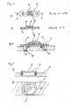
- Weitere Einzelheiten und Vorteile der Erfindung ergeben sich aus der nachfolgenden Beschreibung der anliegenden Zeichnungen von Ausführungsbeispielen. In den Zeichnungen zeigen:
- Fig. 1
- Nicht-erfindungsgemäßes Fixationssystem mit Sensor- und Telemetriesystem auf einer Platte und multidirektional verblockbarer Knochenschraube in einer grobschematischen Perspektivansicht;
- Fig. 2a, b, c
- Fixationssystem mit Sensor- und Telemetriesystem auf einer Platte in einer grobschematischen Perspektivansicht (
Fig. 2a ), in einem Längsschnitt durch den Verbindungsträger (Fig. 2b ) und in einer Seitenansicht (Fig. 2c ); - Fig. 3a, b
- Platte zum Tragen eines Sensors mit einer ovalären Feder in Unteransicht (
Fig. 3a ) und in einem Längsschnitt (Fig. 3b ); - Fig. 4
- Platte gemäß
Fig. 3 mit einem Verbindungsträger verschraubt in einem Längsschnitt, welcher auf der Oberseite eine verkapselte elektronische Einheit aufweist; - Fig. 5
- Nicht-erfindungsgemäße Separate Platte als aufschraubbares Element, welches auf der Innenseite den Dehnungsmeßstreifen aufweist;
- Fig. 6
- Platte mit verkapseltem Sensor- und Telemetriesystem mit Antenne in einem Längsschnitt;
- Fig. 7
- Platte mit verkapseltem Sensor- und Telemetriesystem in einer Kapsel mit Fenster für den Signalaustritt in einem Längsschnitt;
- Fig. 8
- Platte mit Sensor- und Telemetriesystem in einer Kapsel mit Fenster und / oder einer Sendeantenne zur Erleichterung des Signalaustrittes sowie zugeordnete Speicher- und Telemetrieeinheit, welche sich unter der Haut befindet, in Seitenansicht;
- Bei der nachfolgenden Erläuterung verschiedener Ausführungsbeispiele sind einander entsprechende Bauteile mit denselben Bezugsziffern bezeichnet.
- Gemäß
Fig. 1 ist in einem Durchgangsloch 1 eines Verbindungsträgers 2 in Form einer Knochenplatte eine multidirektional verblockbare Knochenschraube 3 eingesetzt. Die Knochenschraube 3 ist mit einem Knochen verschraubbar, wobei von einem Gewinde in der Nähe des Schraubenkopfes 4 ein Gewinde in den Verbindungsträger 2 eingeformt wird. - Ferner ist auf dem Verbindungsträger 2 eine separate Platte 5 mit einem Dehnungsmeßstreifen 6 angeordnet. Die separate Platte 5 ist mittels weiterer Schrauben 7, die in Gewindelöcher 8 des Verbindungsträgers 2 eingedreht sind, mit dem Verbindungsträger 2 verbunden.
- Gemäß
Fig. 2 weist der Verbindungsträger 2 eine in der Draufsicht ovaläre und im Querschnitt konusförmige Nut 9 auf, in die eine komplementäre Feder 10 mit der separaten Platte 5 eingreift. Die separate Platte 5 ist wiederum mittels Schrauben 7, welche die Löcher der separaten Platte 5 durchgreifen und in Gewindelöcher 8 des Verbindungsträgers 2 eingreifen, mit dem Verbindungsträger 2 verschraubt. Hierdurch wird eine besonders innige Verbindung zwischen Platte 5 und Verbindungsträger 2 erzielt, so daß der Kraftfluß durch den Bereich zwischen den Nut-Feder-Verbindungen 9, 10 dem Kraftfluss innerhalb der ovalen Nut 9 des Verbindungsträgers 2 entspricht. - Gemäß
Fig. 3 hat die separate Platte 5 eine ovaläre Feder 10 mit konischem Querschnitt. Die Feder 10 ist in einer komplementären Nut 9 des Verbindungsträgers 2 einfalzbar, wie inFig. 4 gezeigt. Die separate Platte 5 ist mittels der Schrauben 7 fixiert, welche die Löcher 11 der separaten Platte 5 durchgreifen und in die Gewindelöcher 8 des Verbindungsträgers 2' eingeschraubt sind. - Gemäß
Fig. 4 ist das Sensor- und Telemetriesystem 6 innerhalb einer Kapsel 12 auf der Oberseite der separaten Platte 5 angeordnet. - Gemäß
Fig. 5 ist die separate Platte 5 als flache, innen teilweise hohle Schraube angelegt. Sie weist auf der Innenseite die Sensor- und Telemetrieeinheit 6 auf. Das Sensor- und Telemetriesystem 6 kann auch außen aufgebracht werden und ist in diesem Fall von einer Kapsel 12 umgeben. Das Eindrehen dieser einschraubbaren separaten Platte wird durch eine Sechskant-Ausnehmung 17 an der Außenfläche erleichtert. - Gemäß
Fig. 6 weist die separate Platte 5 ein Sensor- und Telemetriesystem 6 mit einer Kapsel 12 auf, wobei aus der Kapsel 12 eine Sendeantenne 13 herausgeführt ist, um eine erleichterte drahtlose Signalübertragung zu gewährleisten. - Gemäß
Fig. 7 ist das Sensor- und Telemetriesystem 6 innerhalb einer Kapsel 12 auf der separaten Platte 5 angeordnet. Die Kapsel 12 weist ein Fenster 14 auf, so daß Signale des Sensor- und Telemetriesystems 6 aus der Kapsel 12 austreten können. - Gemäß
Fig. 8 ist der separaten Platte 5 mit dem Fenster 14 eine weitere, z.B. unter der Haut liegende, Speicher- und Telemetrieeinheit 16 mit einer Empfängerantenne 15 zugeordnet. Die Speicher- und Telemetrieeinheit 16 befindet sich unter der Haut 18 und die Empfängerantenne 15 ist in der Nähe des Fensters 14 angeordnet, so daß eine drahtlose Signalübertragung durch das Fenster 14 und / oder die Sendeantenne 13 auf die Empfängerantenne 15 erfolgen kann. Energie kann der Speicher- und Telemetrieeinheit 16 von außen induktiv zugeführt werden oder die Speicher- und Telemetrieeinheit ist mit einer Batterie versehen, deren Speicherkapazität für die Dauer der Therapie ausreicht.
Claims (28)
- Fixationssystem für Knochen mit einem Verbindungsträger (2), wenigstens einer in ein Durchgangsloch (1) des Verbindungsträgers (2) einsetzbaren Knochenschraube (3) und einem Sensor- und Telemetriesystem (6), wobei das Sensor- und Telemetriesystem (6) auf einer separaten Platte (5) angeordnet ist, die mit dem Verbindungsträger (2) verbindbar ist, dadurch gekennzeichnet, daß Verbindungsträger (2) und separate Platte (5) Einrichtungen zum Ausbilden mindestens einer Nut-Feder-Verbindung (9, 10) zwischen Verbindungsträger (2) und separater Platte (5) aufweisen.
- Fixationssystem nach Anspruch 1, bei dem mindestens eine Knochenschraube (3) im Durchgangsloch (1) befestigbar ist.
- Fixationssystem nach Anspruch 2, bei welchem der Knochenschraubenkopf (3) und /oder das Durchgangsloch (1) ein Gewinde zwischen Knochenschraube und Durchgangsloch aufweisen.
- Fixationssystem nach Ansprüchen 1 bis 3, das Einrichtungen zum form- und/oder kraft- und/oder stoffschlüssigen dauerhaft festen Verbinden (9, 10) von Verbindungsträger (2) und separater Platte (5) aufweist.
- Fixationssystem nach einem der Ansprüche 1 bis 4, bei dem das Sensorsystem (6) einen Dehnungsmeßstreifen umfaßt.
- Fixationssystem nach Anspruch 5, bei dem der Dehnungsmeßstreifen (6) auf die separate Platte (5) aufgeklebt ist.
- Fixationssystem nach Anspruch 6, bei dem die Einrichtungen zum Verbinden (9, 10) auf verschiedenen Seiten des Sensorsystems (6) angeordnet sind.
- Fixationssystem nach einem der Ansprüche 1 bis 7, bei dem der Verbindungsträger (2) mindestens eine Nut (9) und die separate Platte (5) mindestens eine komplementäre Feder (10) zum Einsetzen in die Nut (9) aufweist.
- Fixationssystem nach einem der Ansprüche 1 bis 8, bei dem mehrere Nut-Feder-Verbindungen (9, 10) auf verschiedenen Seiten des Sensorsystems (6) angeordnet sind.
- Fixationssystem nach einem der Ansprüche 1 bis 9, bei dem die Nut (9) kreisförmig oder ovalär und die Feder (10') komplementär zu der Nut (9') geformt ist.
- Fixationssystem nach einem der Ansprüche 1 bis 10, bei dem die separate Platte (5) kreisförmig oder ovalär ist.
- Fixationssystem nach einem der Ansprüche 1 bis 11, bei dem die Nut (9) und die Feder (10) konisch sind.
- Fixationssystem nach einem der Ansprüche 1 bis 12, bei dem die Nut (9) sich zu ihrem Grund hin verjüngt und/oder sich die Feder (10) zu ihrem freien Ende hin verjüngt.
- Fixationssystem nach einem der Ansprüche 1 bis 13, bei dem die separate Platte (5) aus einem härteren Material ist als der Verbindungsträger (2) oder umgekehrt.
- Fixationssystem nach einem der Ansprüche 1 bis 14 mit mindestens einer Schraubverbindung (7, 8) zum Verbinden von separater Platte (5) und Verbindungsträger (2).
- Fixationssystem nach Anspruch 15, bei dem die Schraubverbindung (7, 8) eine Schraube umfaßt, die durch ein Durchgangsloch der separaten Platte (5) in eine Gewindebohrung des Verbindungsträgers (2) einschraubbar ist.
- Fixationssystem nach Anspruch 15 oder 16, bei dem die separate Platte (5) mittels mindestens zwei einander diametral gegenüberliegender Schraubverbindungen (7, 8) mit dem Verbindungsträger (2) verbindbar ist.
- Fixationssystem nach einem der Ansprüche 1 bis 17, bei dem das Sensor- und/oder Telemetriesystem (6) zumindest teilweise unterhalb der separaten Platte (5) in einem von der Nut-Feder-Verbindung (9, 10) umschlossenen Bereich angeordnet ist.
- Fixationssystem nach einem der Ansprüche 1 bis 15, bei dem das Sensor- und/oder Telemetriesystem (6) zumindest teilweise in einer auf der Oberseite der separaten Platte (5) angeordneten Kapsel (12) angeordnet ist.
- Fixationssystem nach Anspruch 19, bei dem die Kapsel (12) aus Metall oder Kunststoff besteht.
- Fixationssystem nach einem der Ansprüche 1 bis 20, bei dem die separate Platte (5) als flache, innen hohle Schraube ausgestaltet ist, welche in ein Teilloch des Verbindungsträgers eingeschraubt wird.
- Fixationssystem nach Anspruch 20 und 21, bei dem die metallische Kapsel (12) ein Fenster (14) aufweist.
- Fixationssystem nach einem der Ansprüche 1 bis 22, bei dem das Sensor- und Telemetriesystem (6) eine Sendeantenne (13) aufweist.
- Fixationssystem nach Anspruch 23, bei dem die Sendeantenne (13) innerhalb des subkutanen Gewebes platziert werden kann.
- Fixationssystem nach Anspruch 23 oder 24, bei dem die Sendeantenne (13) eine Steckverbindung mit dem Sensor- und Telemetriesystem (6) aufweist.
- Fixationssystem nach einem der Ansprüche 1 bis 25, das eine unter der Haut anordenbare Speicher- und Telemetrieeinheit (16) mit einer in der Nähe des Sensor- und Telemetriesystems (6) platzierbaren Empfängerantenne (15) umfaßt.
- Fixationssystem nach einem der Ansprüche 1 bis 26, bei dem das Sensor- und Telemetriesystem (6) und/oder die Speicher- und Telemetrieeinheit (16) eine Energieversorgung durch Induktion und/oder durch mindestens ein Batteriesystem und/oder durch mindestens ein Akkusystem und/oder mindestens einen Kondensator aufweist.
- Fixationssystem nach einem der Ansprüche 1 bis 27, bei dem der Verbindungsträger (2) eine Knochenplatte, ein Marknagel oder ein Fixateur externe ist.
Applications Claiming Priority (2)
| Application Number | Priority Date | Filing Date | Title |
|---|---|---|---|
| DE102006006341A DE102006006341A1 (de) | 2006-02-07 | 2006-02-07 | Fixationssystem für Knochen mit einem Sensor- und Telemetriesystem |
| PCT/EP2007/000794 WO2007090543A1 (de) | 2006-02-07 | 2007-01-30 | Fixationssystem für knochen mit einem sensor- und telemetriesystem |
Publications (3)
| Publication Number | Publication Date |
|---|---|
| EP1981418A1 EP1981418A1 (de) | 2008-10-22 |
| EP1981418B1 true EP1981418B1 (de) | 2015-03-18 |
| EP1981418B8 EP1981418B8 (de) | 2015-04-22 |
Family
ID=37999021
Family Applications (1)
| Application Number | Title | Priority Date | Filing Date |
|---|---|---|---|
| EP20070703148 Not-in-force EP1981418B8 (de) | 2006-02-07 | 2007-01-30 | Fixationssystem für knochen mit einem sensor- und telemetriesystem |
Country Status (5)
| Country | Link |
|---|---|
| US (1) | US8926674B2 (de) |
| EP (1) | EP1981418B8 (de) |
| DE (1) | DE102006006341A1 (de) |
| RU (1) | RU2424781C2 (de) |
| WO (1) | WO2007090543A1 (de) |
Families Citing this family (30)
| Publication number | Priority date | Publication date | Assignee | Title |
|---|---|---|---|---|
| WO2006052765A2 (en) | 2004-11-04 | 2006-05-18 | Smith & Nephew, Inc. | Cycle and load measurement device |
| EP1924211B1 (de) | 2005-08-23 | 2019-12-18 | Smith & Nephew, Inc. | Telemetrisches orthopädisches implantat |
| US9445720B2 (en) | 2007-02-23 | 2016-09-20 | Smith & Nephew, Inc. | Processing sensed accelerometer data for determination of bone healing |
| ES2611597T3 (es) | 2007-09-06 | 2017-05-09 | Smith & Nephew, Inc. | Sistema y método para comunicar con un implante telemétrico |
| DE102008063844B4 (de) | 2008-12-19 | 2014-11-06 | Berufsgenossenschaftliches Unfallkrankenhaus Hamburg | Messvorrichtung zur Bestimmung einer Biegung eines länglichen internen Osteosynthese-Fixateurs |
| US8704124B2 (en) | 2009-01-29 | 2014-04-22 | Smith & Nephew, Inc. | Low temperature encapsulate welding |
| US9844333B2 (en) | 2009-03-24 | 2017-12-19 | International Business Machines Corporation | Remote delivery and monitoring of health care |
| WO2010115458A1 (en) | 2009-04-08 | 2010-10-14 | Stryker Trauma Gmbh | Hybrid bone plate |
| US8282636B2 (en) | 2009-08-10 | 2012-10-09 | Imds Corporation | Orthopedic external fixator and method of use |
| US9066757B2 (en) | 2009-08-10 | 2015-06-30 | Virak Orthopedic Research Llc | Orthopedic external fixator and method of use |
| KR101713302B1 (ko) | 2009-10-21 | 2017-03-07 | 신세스 게엠바하 | 뼈 치유 평가용 임플란트 하중 판독의 정규화 방법 |
| US8777947B2 (en) * | 2010-03-19 | 2014-07-15 | Smith & Nephew, Inc. | Telescoping IM nail and actuating mechanism |
| DE102010022434A1 (de) * | 2010-06-02 | 2011-12-08 | Berufsgenossenschaftliches Unfallkrankenhaus Hamburg | Fixationssystem für Knochen mit einem Sensorsystem |
| RU2012157125A (ru) * | 2010-06-03 | 2014-07-20 | Смит Энд Нефью, Инк. | Ортопедический имплантат |
| BR112013029376A2 (pt) | 2011-05-16 | 2017-01-31 | Smith & Nephew Inc | medição de extensão do esqueleto |
| DE102011115283A1 (de) | 2011-09-29 | 2013-04-04 | Berufsgenossenschaftliches Unfallkrankenhaus Hamburg | Verfahren und System zum automatischen Bestimmen der elastischen Nachgiebigkeit eines Knochens im Verlauf einer Frakturheilung |
| US9795423B2 (en) * | 2012-01-23 | 2017-10-24 | DePuy Synthes Products, Inc. | Device and method for normalizing implant strain readings to assess bone healing |
| US10060738B2 (en) * | 2014-08-26 | 2018-08-28 | 4Iiii Innovations Inc. | Adhesively coupled power-meter for measurement of force, torque, and power and associated methods |
| CA2982388C (en) * | 2015-04-27 | 2023-08-08 | Ao Technology Ag | Kit for assembling a medical device provided with data acquisition means |
| US10695113B2 (en) * | 2015-08-07 | 2020-06-30 | Ao Technology Ag | Bone plate |
| EP3433592B1 (de) | 2016-03-21 | 2024-12-25 | 4IIII Innovations Inc. | System und verfahren zur fahrradleistungsmessung und energieversorgung |
| JP7167129B2 (ja) | 2017-08-07 | 2022-11-08 | デピュイ・シンセス・プロダクツ・インコーポレイテッド | 患者の身体に埋め込み可能なセンサ、それを使用するシステム及び方法 |
| US11707224B2 (en) | 2019-06-28 | 2023-07-25 | Orthosensor, Inc. | Orthopedic system for pre-operative, intraoperative, and post-operative assessment |
| EP4048138A1 (de) * | 2019-10-22 | 2022-08-31 | AO Technology AG | Vorrichtung zur messung, verarbeitung und übertragung von implantatparametern |
| US12514505B2 (en) | 2020-08-31 | 2026-01-06 | DePuy Synthes Products, Inc. | Hermetic enclosure for implantable sensors |
| US12484855B2 (en) * | 2020-12-31 | 2025-12-02 | Martin Roche | Pre-operative, intra-operative, and post-operative patient management |
| US11806054B2 (en) | 2021-02-23 | 2023-11-07 | Nuvasive Specialized Orthopedics, Inc. | Adjustable implant, system and methods |
| US12458417B2 (en) | 2022-08-15 | 2025-11-04 | Nuvasive Specialized Orthopedics Inc. | Intermedullary lengthening implant with integrated load sensor |
| IT202300015768A1 (it) * | 2023-07-26 | 2025-01-26 | Orthofix Srl | Dispositivo fissatore interno sensorizzato e relativo apparato di monitoraggio per intervento di epifisiodesi |
| GB2643111A (en) | 2024-07-30 | 2026-02-11 | Sensirion Ag | Sensor device in the format of a bone screw, nail or pin |
Family Cites Families (18)
| Publication number | Priority date | Publication date | Assignee | Title |
|---|---|---|---|---|
| DE8513288U1 (de) * | 1985-05-06 | 1986-09-04 | Wolter, Dietmar, Prof. Dr., 2000 Hamburg | Osteosyntheseplatte |
| AT386117B (de) | 1986-02-03 | 1988-07-11 | Ludwig Dr Med Auer | Einrichtung zur ermittlung des druckverlaufes an geraeten fuer operative eingriffe |
| SU1560173A1 (ru) * | 1988-02-29 | 1990-04-30 | Пензенский государственный институт усовершенствования врачей | Устройство дл бесконтактной передачи информации об усили х нагружени на позвоночник |
| US5425775A (en) * | 1992-06-23 | 1995-06-20 | N.K. Biotechnical Engineering Company | Method for measuring patellofemoral forces |
| DE4329898A1 (de) * | 1993-09-04 | 1995-04-06 | Marcus Dr Besson | Kabelloses medizinisches Diagnose- und Überwachungsgerät |
| DE4343117C2 (de) | 1993-12-17 | 1999-11-04 | Dietmar Wolter | Fixationssystem für Knochen |
| RU4675U1 (ru) * | 1996-06-04 | 1997-08-16 | Российский научный центр "Восстановительная травматология и ортопедия" им.акад.Г.А.Илизарова | Датчик для измерения усилий при удлинении конечности |
| DE19711628A1 (de) | 1997-01-17 | 1998-07-23 | Ceramtec Ag | Fixation eines keramischen Bauteils als Gleitkomponente in einem Femurteil |
| US6034296A (en) * | 1997-03-11 | 2000-03-07 | Elvin; Niell | Implantable bone strain telemetry sensing system and method |
| RU2127090C1 (ru) * | 1997-12-24 | 1999-03-10 | Саратовский научно-исследовательский институт травматологии и ортопедии | Устройство для коррекции и диагностики при хирургическом лечении деформаций позвоночника |
| DE19856013A1 (de) | 1998-12-04 | 2000-06-08 | Wittenstein Gmbh & Co Kg | Distraktionsvorrichtung |
| DE19858889B4 (de) | 1998-12-19 | 2008-08-07 | Wolter, Dietmar, Prof. Dr.Med. | Fixationssystem für Knochen |
| EP1513584A2 (de) * | 2002-06-04 | 2005-03-16 | Cyberkinetics, Inc. | Optisch verbundene implantate, darauf bezogene systeme und deren verwendung |
| DE20213235U1 (de) | 2002-08-24 | 2002-10-17 | Tantum AG, 24534 Neumünster | Intramedullärer Osteosynthese-Nagel zum Versorgen von Röhrenknochenfrakturen |
| US7218232B2 (en) * | 2003-07-11 | 2007-05-15 | Depuy Products, Inc. | Orthopaedic components with data storage element |
| US7250060B2 (en) * | 2004-01-27 | 2007-07-31 | Sdgi Holdings, Inc. | Hybrid intervertebral disc system |
| DE102004006501A1 (de) | 2004-02-10 | 2005-09-01 | Charité-Universitätsmedizin Berlin | Bauteil und Verfahren zum Zusammenbau einer Implantatanordnung |
| US7708777B2 (en) * | 2006-02-03 | 2010-05-04 | Depuy Spine, Inc. | Modular intervertebral disc replacements |
-
2006
- 2006-02-07 DE DE102006006341A patent/DE102006006341A1/de not_active Withdrawn
-
2007
- 2007-01-30 US US12/278,346 patent/US8926674B2/en not_active Expired - Fee Related
- 2007-01-30 EP EP20070703148 patent/EP1981418B8/de not_active Not-in-force
- 2007-01-30 RU RU2008135955/14A patent/RU2424781C2/ru not_active IP Right Cessation
- 2007-01-30 WO PCT/EP2007/000794 patent/WO2007090543A1/de not_active Ceased
Also Published As
| Publication number | Publication date |
|---|---|
| WO2007090543A1 (de) | 2007-08-16 |
| DE102006006341A1 (de) | 2007-08-09 |
| EP1981418A1 (de) | 2008-10-22 |
| RU2008135955A (ru) | 2010-03-20 |
| US20090222050A1 (en) | 2009-09-03 |
| RU2424781C2 (ru) | 2011-07-27 |
| US8926674B2 (en) | 2015-01-06 |
| EP1981418B8 (de) | 2015-04-22 |
Similar Documents
| Publication | Publication Date | Title |
|---|---|---|
| EP1981418A1 (de) | Fixationssystem für knochen mit einem sensor- und telemetriesystem | |
| EP2229878B1 (de) | Akustisches und elektromagnetisches Datenübertragungssystem, integriert in ein Implantat | |
| EP2422731B1 (de) | Aktuator zur Skoliosekorrektur | |
| DE60023036T2 (de) | Vorrichtung zum in-vivo-messen von druck und druckschwankugen im oder am knochen | |
| DE60119890T2 (de) | Handfixierungsvorrichtung | |
| EP1691701B1 (de) | Osteosyntheseplatten-Set | |
| DE69726746T2 (de) | Mehrachsige knochenschraubeanordnung | |
| EP2750617B1 (de) | Anatomisch angepasste, plantare knochenplatte sowie knochenplattensystem | |
| EP0565216B1 (de) | Marknagel | |
| DE60023886T2 (de) | Multi-axialer knochenanker | |
| DE102005042751B4 (de) | System, Einrichtung und Verfahren zum Ad-hoc-Nachverfolgen eines Objektes | |
| EP1531723B1 (de) | Vorrichtung zur messung von parametern im hirn | |
| EP0559870B1 (de) | Platte zur osteosynthese | |
| DE9002087U1 (de) | Äußerliche Befestigungseinrichtung mit regelbarer Federung | |
| WO2005074821A2 (de) | Bauteil und verfahren zum zusammenbau einer implantatanordnung | |
| EP3582713B1 (de) | Medizinische befestigungseinrichtung und medizinische vorrichtung | |
| DE102005019755A1 (de) | Blutdruckmessgerät | |
| EP1926445B1 (de) | Osteosynthesehilfsmittel | |
| DE102008063844B4 (de) | Messvorrichtung zur Bestimmung einer Biegung eines länglichen internen Osteosynthese-Fixateurs | |
| EP1643917A1 (de) | Zielvorrichtung | |
| DE102010022434A1 (de) | Fixationssystem für Knochen mit einem Sensorsystem | |
| DE102013111354A1 (de) | Fixateur interne | |
| DE102004061543B4 (de) | Implantat zur intraokularen Druckmessung | |
| DE212018000187U1 (de) | Diskrete bioelektrische Impedanzermittlungseinrichtung | |
| DE102006018867B3 (de) | Osteosynthetisches System |
Legal Events
| Date | Code | Title | Description |
|---|---|---|---|
| PUAI | Public reference made under article 153(3) epc to a published international application that has entered the european phase |
Free format text: ORIGINAL CODE: 0009012 |
|
| 17P | Request for examination filed |
Effective date: 20080801 |
|
| AK | Designated contracting states |
Kind code of ref document: A1 Designated state(s): AT BE BG CH CY CZ DE DK EE ES FI FR GB GR HU IE IS IT LI LT LU LV MC NL PL PT RO SE SI SK TR |
|
| DAX | Request for extension of the european patent (deleted) | ||
| RAP1 | Party data changed (applicant data changed or rights of an application transferred) |
Owner name: WOLTER, DIETMAR |
|
| GRAP | Despatch of communication of intention to grant a patent |
Free format text: ORIGINAL CODE: EPIDOSNIGR1 |
|
| RAP1 | Party data changed (applicant data changed or rights of an application transferred) |
Owner name: WOLTER, DIETMAR |
|
| INTG | Intention to grant announced |
Effective date: 20141013 |
|
| GRAS | Grant fee paid |
Free format text: ORIGINAL CODE: EPIDOSNIGR3 |
|
| GRAA | (expected) grant |
Free format text: ORIGINAL CODE: 0009210 |
|
| AK | Designated contracting states |
Kind code of ref document: B1 Designated state(s): AT BE BG CH CY CZ DE DK EE ES FI FR GB GR HU IE IS IT LI LT LU LV MC NL PL PT RO SE SI SK TR |
|
| REG | Reference to a national code |
Ref country code: GB Ref legal event code: FG4D Free format text: NOT ENGLISH |
|
| REG | Reference to a national code |
Ref country code: CH Ref legal event code: EP |
|
| REG | Reference to a national code |
Ref country code: IE Ref legal event code: FG4D Free format text: LANGUAGE OF EP DOCUMENT: GERMAN |
|
| RIN2 | Information on inventor provided after grant (corrected) |
Inventor name: WOLTER, DIETMAR PROF. DR. Inventor name: CAPANNI, FELIX |
|
| REG | Reference to a national code |
Ref country code: AT Ref legal event code: REF Ref document number: 716026 Country of ref document: AT Kind code of ref document: T Effective date: 20150415 |
|
| RIN2 | Information on inventor provided after grant (corrected) |
Inventor name: CAPANNI, FELIX Inventor name: WOLTER, DIETMAR PROF. DR. |
|
| RIN2 | Information on inventor provided after grant (corrected) |
Inventor name: CAPANNI, FELIX Inventor name: WOLTER, DIETMAR PROF. DR. |
|
| REG | Reference to a national code |
Ref country code: DE Ref legal event code: R096 Ref document number: 502007013800 Country of ref document: DE Effective date: 20150430 |
|
| REG | Reference to a national code |
Ref country code: NL Ref legal event code: VDEP Effective date: 20150318 |
|
| REG | Reference to a national code |
Ref country code: NL Ref legal event code: VDEP Effective date: 20150318 |
|
| PG25 | Lapsed in a contracting state [announced via postgrant information from national office to epo] |
Ref country code: LT Free format text: LAPSE BECAUSE OF FAILURE TO SUBMIT A TRANSLATION OF THE DESCRIPTION OR TO PAY THE FEE WITHIN THE PRESCRIBED TIME-LIMIT Effective date: 20150318 Ref country code: SE Free format text: LAPSE BECAUSE OF FAILURE TO SUBMIT A TRANSLATION OF THE DESCRIPTION OR TO PAY THE FEE WITHIN THE PRESCRIBED TIME-LIMIT Effective date: 20150318 Ref country code: FI Free format text: LAPSE BECAUSE OF FAILURE TO SUBMIT A TRANSLATION OF THE DESCRIPTION OR TO PAY THE FEE WITHIN THE PRESCRIBED TIME-LIMIT Effective date: 20150318 |
|
| REG | Reference to a national code |
Ref country code: LT Ref legal event code: MG4D |
|
| PG25 | Lapsed in a contracting state [announced via postgrant information from national office to epo] |
Ref country code: GR Free format text: LAPSE BECAUSE OF FAILURE TO SUBMIT A TRANSLATION OF THE DESCRIPTION OR TO PAY THE FEE WITHIN THE PRESCRIBED TIME-LIMIT Effective date: 20150619 Ref country code: LV Free format text: LAPSE BECAUSE OF FAILURE TO SUBMIT A TRANSLATION OF THE DESCRIPTION OR TO PAY THE FEE WITHIN THE PRESCRIBED TIME-LIMIT Effective date: 20150318 |
|
| PG25 | Lapsed in a contracting state [announced via postgrant information from national office to epo] |
Ref country code: NL Free format text: LAPSE BECAUSE OF FAILURE TO SUBMIT A TRANSLATION OF THE DESCRIPTION OR TO PAY THE FEE WITHIN THE PRESCRIBED TIME-LIMIT Effective date: 20150318 |
|
| PG25 | Lapsed in a contracting state [announced via postgrant information from national office to epo] |
Ref country code: PT Free format text: LAPSE BECAUSE OF FAILURE TO SUBMIT A TRANSLATION OF THE DESCRIPTION OR TO PAY THE FEE WITHIN THE PRESCRIBED TIME-LIMIT Effective date: 20150720 Ref country code: EE Free format text: LAPSE BECAUSE OF FAILURE TO SUBMIT A TRANSLATION OF THE DESCRIPTION OR TO PAY THE FEE WITHIN THE PRESCRIBED TIME-LIMIT Effective date: 20150318 Ref country code: ES Free format text: LAPSE BECAUSE OF FAILURE TO SUBMIT A TRANSLATION OF THE DESCRIPTION OR TO PAY THE FEE WITHIN THE PRESCRIBED TIME-LIMIT Effective date: 20150318 Ref country code: SK Free format text: LAPSE BECAUSE OF FAILURE TO SUBMIT A TRANSLATION OF THE DESCRIPTION OR TO PAY THE FEE WITHIN THE PRESCRIBED TIME-LIMIT Effective date: 20150318 Ref country code: CZ Free format text: LAPSE BECAUSE OF FAILURE TO SUBMIT A TRANSLATION OF THE DESCRIPTION OR TO PAY THE FEE WITHIN THE PRESCRIBED TIME-LIMIT Effective date: 20150318 Ref country code: RO Free format text: LAPSE BECAUSE OF FAILURE TO SUBMIT A TRANSLATION OF THE DESCRIPTION OR TO PAY THE FEE WITHIN THE PRESCRIBED TIME-LIMIT Effective date: 20150318 |
|
| PG25 | Lapsed in a contracting state [announced via postgrant information from national office to epo] |
Ref country code: PL Free format text: LAPSE BECAUSE OF FAILURE TO SUBMIT A TRANSLATION OF THE DESCRIPTION OR TO PAY THE FEE WITHIN THE PRESCRIBED TIME-LIMIT Effective date: 20150318 Ref country code: IS Free format text: LAPSE BECAUSE OF FAILURE TO SUBMIT A TRANSLATION OF THE DESCRIPTION OR TO PAY THE FEE WITHIN THE PRESCRIBED TIME-LIMIT Effective date: 20150718 |
|
| REG | Reference to a national code |
Ref country code: DE Ref legal event code: R097 Ref document number: 502007013800 Country of ref document: DE |
|
| PG25 | Lapsed in a contracting state [announced via postgrant information from national office to epo] |
Ref country code: IT Free format text: LAPSE BECAUSE OF FAILURE TO SUBMIT A TRANSLATION OF THE DESCRIPTION OR TO PAY THE FEE WITHIN THE PRESCRIBED TIME-LIMIT Effective date: 20150318 |
|
| REG | Reference to a national code |
Ref country code: FR Ref legal event code: PLFP Year of fee payment: 10 |
|
| PLBE | No opposition filed within time limit |
Free format text: ORIGINAL CODE: 0009261 |
|
| STAA | Information on the status of an ep patent application or granted ep patent |
Free format text: STATUS: NO OPPOSITION FILED WITHIN TIME LIMIT |
|
| PG25 | Lapsed in a contracting state [announced via postgrant information from national office to epo] |
Ref country code: DK Free format text: LAPSE BECAUSE OF FAILURE TO SUBMIT A TRANSLATION OF THE DESCRIPTION OR TO PAY THE FEE WITHIN THE PRESCRIBED TIME-LIMIT Effective date: 20150318 |
|
| 26N | No opposition filed |
Effective date: 20151221 |
|
| PG25 | Lapsed in a contracting state [announced via postgrant information from national office to epo] |
Ref country code: SI Free format text: LAPSE BECAUSE OF FAILURE TO SUBMIT A TRANSLATION OF THE DESCRIPTION OR TO PAY THE FEE WITHIN THE PRESCRIBED TIME-LIMIT Effective date: 20150318 |
|
| PG25 | Lapsed in a contracting state [announced via postgrant information from national office to epo] |
Ref country code: BE Free format text: LAPSE BECAUSE OF NON-PAYMENT OF DUE FEES Effective date: 20160131 |
|
| PG25 | Lapsed in a contracting state [announced via postgrant information from national office to epo] |
Ref country code: LU Free format text: LAPSE BECAUSE OF FAILURE TO SUBMIT A TRANSLATION OF THE DESCRIPTION OR TO PAY THE FEE WITHIN THE PRESCRIBED TIME-LIMIT Effective date: 20160130 |
|
| REG | Reference to a national code |
Ref country code: CH Ref legal event code: PL |
|
| PG25 | Lapsed in a contracting state [announced via postgrant information from national office to epo] |
Ref country code: MC Free format text: LAPSE BECAUSE OF FAILURE TO SUBMIT A TRANSLATION OF THE DESCRIPTION OR TO PAY THE FEE WITHIN THE PRESCRIBED TIME-LIMIT Effective date: 20150318 |
|
| PG25 | Lapsed in a contracting state [announced via postgrant information from national office to epo] |
Ref country code: LI Free format text: LAPSE BECAUSE OF NON-PAYMENT OF DUE FEES Effective date: 20160131 Ref country code: CH Free format text: LAPSE BECAUSE OF NON-PAYMENT OF DUE FEES Effective date: 20160131 |
|
| REG | Reference to a national code |
Ref country code: IE Ref legal event code: MM4A |
|
| REG | Reference to a national code |
Ref country code: FR Ref legal event code: PLFP Year of fee payment: 11 |
|
| PG25 | Lapsed in a contracting state [announced via postgrant information from national office to epo] |
Ref country code: IE Free format text: LAPSE BECAUSE OF NON-PAYMENT OF DUE FEES Effective date: 20160130 |
|
| REG | Reference to a national code |
Ref country code: AT Ref legal event code: MM01 Ref document number: 716026 Country of ref document: AT Kind code of ref document: T Effective date: 20160130 |
|
| PG25 | Lapsed in a contracting state [announced via postgrant information from national office to epo] |
Ref country code: AT Free format text: LAPSE BECAUSE OF NON-PAYMENT OF DUE FEES Effective date: 20160130 |
|
| REG | Reference to a national code |
Ref country code: FR Ref legal event code: PLFP Year of fee payment: 12 |
|
| PG25 | Lapsed in a contracting state [announced via postgrant information from national office to epo] |
Ref country code: HU Free format text: LAPSE BECAUSE OF FAILURE TO SUBMIT A TRANSLATION OF THE DESCRIPTION OR TO PAY THE FEE WITHIN THE PRESCRIBED TIME-LIMIT; INVALID AB INITIO Effective date: 20070130 Ref country code: CY Free format text: LAPSE BECAUSE OF FAILURE TO SUBMIT A TRANSLATION OF THE DESCRIPTION OR TO PAY THE FEE WITHIN THE PRESCRIBED TIME-LIMIT Effective date: 20150318 |
|
| PG25 | Lapsed in a contracting state [announced via postgrant information from national office to epo] |
Ref country code: TR Free format text: LAPSE BECAUSE OF FAILURE TO SUBMIT A TRANSLATION OF THE DESCRIPTION OR TO PAY THE FEE WITHIN THE PRESCRIBED TIME-LIMIT Effective date: 20150318 |
|
| PG25 | Lapsed in a contracting state [announced via postgrant information from national office to epo] |
Ref country code: BG Free format text: LAPSE BECAUSE OF FAILURE TO SUBMIT A TRANSLATION OF THE DESCRIPTION OR TO PAY THE FEE WITHIN THE PRESCRIBED TIME-LIMIT Effective date: 20150318 |
|
| PGFP | Annual fee paid to national office [announced via postgrant information from national office to epo] |
Ref country code: GB Payment date: 20200127 Year of fee payment: 14 Ref country code: DE Payment date: 20200325 Year of fee payment: 14 |
|
| PGFP | Annual fee paid to national office [announced via postgrant information from national office to epo] |
Ref country code: FR Payment date: 20200123 Year of fee payment: 14 |
|
| REG | Reference to a national code |
Ref country code: DE Ref legal event code: R119 Ref document number: 502007013800 Country of ref document: DE |
|
| GBPC | Gb: european patent ceased through non-payment of renewal fee |
Effective date: 20210130 |
|
| PG25 | Lapsed in a contracting state [announced via postgrant information from national office to epo] |
Ref country code: FR Free format text: LAPSE BECAUSE OF NON-PAYMENT OF DUE FEES Effective date: 20210131 |
|
| PG25 | Lapsed in a contracting state [announced via postgrant information from national office to epo] |
Ref country code: DE Free format text: LAPSE BECAUSE OF NON-PAYMENT OF DUE FEES Effective date: 20210803 Ref country code: GB Free format text: LAPSE BECAUSE OF NON-PAYMENT OF DUE FEES Effective date: 20210130 |