EP1980817A2 - Beam scanning imaging method and apparatus - Google Patents
Beam scanning imaging method and apparatus Download PDFInfo
- Publication number
- EP1980817A2 EP1980817A2 EP08006455A EP08006455A EP1980817A2 EP 1980817 A2 EP1980817 A2 EP 1980817A2 EP 08006455 A EP08006455 A EP 08006455A EP 08006455 A EP08006455 A EP 08006455A EP 1980817 A2 EP1980817 A2 EP 1980817A2
- Authority
- EP
- European Patent Office
- Prior art keywords
- target
- thz
- wave
- optics
- imaging
- Prior art date
- Legal status (The legal status is an assumption and is not a legal conclusion. Google has not performed a legal analysis and makes no representation as to the accuracy of the status listed.)
- Withdrawn
Links
- 238000003384 imaging method Methods 0.000 title claims abstract description 73
- 238000001514 detection method Methods 0.000 claims abstract description 10
- 238000006243 chemical reaction Methods 0.000 claims abstract 2
- 230000002123 temporal effect Effects 0.000 claims description 23
- 238000000034 method Methods 0.000 claims description 19
- 230000003287 optical effect Effects 0.000 claims description 18
- 230000005855 radiation Effects 0.000 claims description 16
- 238000009826 distribution Methods 0.000 claims description 14
- 230000005540 biological transmission Effects 0.000 claims description 7
- 238000006073 displacement reaction Methods 0.000 claims description 7
- 238000005259 measurement Methods 0.000 claims description 5
- 230000001427 coherent effect Effects 0.000 claims description 2
- 230000003595 spectral effect Effects 0.000 claims description 2
- 230000001360 synchronised effect Effects 0.000 claims description 2
- 238000000701 chemical imaging Methods 0.000 claims 1
- 230000035945 sensitivity Effects 0.000 abstract description 3
- 238000010586 diagram Methods 0.000 description 13
- 238000005516 engineering process Methods 0.000 description 7
- 239000013078 crystal Substances 0.000 description 6
- 239000008188 pellet Substances 0.000 description 6
- 239000007787 solid Substances 0.000 description 5
- 238000003491 array Methods 0.000 description 4
- 239000004698 Polyethylene Substances 0.000 description 3
- -1 polyethylene Polymers 0.000 description 3
- 229920000573 polyethylene Polymers 0.000 description 3
- 238000005086 pumping Methods 0.000 description 3
- XUIMIQQOPSSXEZ-UHFFFAOYSA-N Silicon Chemical compound [Si] XUIMIQQOPSSXEZ-UHFFFAOYSA-N 0.000 description 2
- 229910007709 ZnTe Inorganic materials 0.000 description 2
- 238000005452 bending Methods 0.000 description 2
- 239000004033 plastic Substances 0.000 description 2
- 229920003023 plastic Polymers 0.000 description 2
- 230000010287 polarization Effects 0.000 description 2
- 229910052710 silicon Inorganic materials 0.000 description 2
- 239000010703 silicon Substances 0.000 description 2
- 238000013519 translation Methods 0.000 description 2
- 230000000903 blocking effect Effects 0.000 description 1
- 230000000295 complement effect Effects 0.000 description 1
- 239000003989 dielectric material Substances 0.000 description 1
- 238000010790 dilution Methods 0.000 description 1
- 239000012895 dilution Substances 0.000 description 1
- 230000000694 effects Effects 0.000 description 1
- 238000010894 electron beam technology Methods 0.000 description 1
- 238000002474 experimental method Methods 0.000 description 1
- 238000007689 inspection Methods 0.000 description 1
- 238000013507 mapping Methods 0.000 description 1
- 239000002184 metal Substances 0.000 description 1
- 238000012986 modification Methods 0.000 description 1
- 230000004048 modification Effects 0.000 description 1
- 239000002086 nanomaterial Substances 0.000 description 1
- 239000003921 oil Substances 0.000 description 1
- 239000000123 paper Substances 0.000 description 1
- 238000012545 processing Methods 0.000 description 1
- 238000003908 quality control method Methods 0.000 description 1
- 238000013341 scale-up Methods 0.000 description 1
- 238000011896 sensitive detection Methods 0.000 description 1
- 239000000779 smoke Substances 0.000 description 1
- 238000001228 spectrum Methods 0.000 description 1
- 239000004575 stone Substances 0.000 description 1
- 230000001629 suppression Effects 0.000 description 1
- 230000001960 triggered effect Effects 0.000 description 1
- 238000012285 ultrasound imaging Methods 0.000 description 1
- 238000009827 uniform distribution Methods 0.000 description 1
- 239000002023 wood Substances 0.000 description 1
Images












Classifications
-
- G—PHYSICS
- G01—MEASURING; TESTING
- G01B—MEASURING LENGTH, THICKNESS OR SIMILAR LINEAR DIMENSIONS; MEASURING ANGLES; MEASURING AREAS; MEASURING IRREGULARITIES OF SURFACES OR CONTOURS
- G01B15/00—Measuring arrangements characterised by the use of electromagnetic waves or particle radiation, e.g. by the use of microwaves, X-rays, gamma rays or electrons
- G01B15/04—Measuring arrangements characterised by the use of electromagnetic waves or particle radiation, e.g. by the use of microwaves, X-rays, gamma rays or electrons for measuring contours or curvatures
-
- G—PHYSICS
- G01—MEASURING; TESTING
- G01B—MEASURING LENGTH, THICKNESS OR SIMILAR LINEAR DIMENSIONS; MEASURING ANGLES; MEASURING AREAS; MEASURING IRREGULARITIES OF SURFACES OR CONTOURS
- G01B11/00—Measuring arrangements characterised by the use of optical techniques
- G01B11/24—Measuring arrangements characterised by the use of optical techniques for measuring contours or curvatures
-
- G—PHYSICS
- G01—MEASURING; TESTING
- G01N—INVESTIGATING OR ANALYSING MATERIALS BY DETERMINING THEIR CHEMICAL OR PHYSICAL PROPERTIES
- G01N21/00—Investigating or analysing materials by the use of optical means, i.e. using sub-millimetre waves, infrared, visible or ultraviolet light
- G01N21/17—Systems in which incident light is modified in accordance with the properties of the material investigated
- G01N21/25—Colour; Spectral properties, i.e. comparison of effect of material on the light at two or more different wavelengths or wavelength bands
- G01N21/31—Investigating relative effect of material at wavelengths characteristic of specific elements or molecules, e.g. atomic absorption spectrometry
- G01N21/35—Investigating relative effect of material at wavelengths characteristic of specific elements or molecules, e.g. atomic absorption spectrometry using infrared light
- G01N21/3581—Investigating relative effect of material at wavelengths characteristic of specific elements or molecules, e.g. atomic absorption spectrometry using infrared light using far infrared light; using Terahertz radiation
-
- G—PHYSICS
- G01—MEASURING; TESTING
- G01N—INVESTIGATING OR ANALYSING MATERIALS BY DETERMINING THEIR CHEMICAL OR PHYSICAL PROPERTIES
- G01N22/00—Investigating or analysing materials by the use of microwaves or radio waves, i.e. electromagnetic waves with a wavelength of one millimetre or more
Definitions
- This invention relates to imaging technology, and more particularly an imaging process using terahertz electro-magnetic waves.
- the invention is an apparatus designed for scanning and collecting for the imaging information.
- Electro-magnetic waves in the frequency range located between infrared and microwave, are one of the latest developed areas of spectrum. This band is often referred to as the terahertz (THz) band. These waves are transparent for most non-polar dielectrics, such as plastic, paper, stone, wood, oil, smoke, et. al. This makes THz wave imaging an ideal tool as a complement to x-ray and ultrasound imaging in security inspection and quality control applications. Additionally, THz wave imaging provides spectroscopic information on the target, and it can be used to identify the target. THz wave imaging is safe to both the sample and the operator as THz photons have very low energy (meV), which will not ionize molecules.
- meV very low energy
- THz wave imaging technology such as described in U.S. Patent No. 5,623,145 and U.S. Patent No. 5,710,430 to M. Nuss , demonstrated the capability of seeing through plastic and mapping metal electrodes underneath.
- Most THz wave imaging apparatuses developed since then use a raster scanning mode to image the target. THz radiation emitted from the source is focused on the target imaged, and is recorded using a point detector after interacting with the target through transmission or reflection. The target is imaged via scanning the target crossing the THz wave focal spot in an X-Y plane or alternatively scanning the imager in opposite directions. Raster scanning fully utilizes THz waves generated from the source and results in a high measurement dynamic range, which is especially important in the THz regime where lack of intense sources and sensitive detectors pose a problem.
- Raster scanning an image requires linearly scanning either the target or the imager within the entire image area, which is not only time consuming but also inconvenient.
- 2D focal plane imaging which uses a 2D extended detector (such as an electro-optical (EO) crystal) or a detector array (such as a microbolometer array) instead of a point detector to record the distribution of the THz field at the image plane, was developed to improve imaging speed.
- EO electro-optical
- a detector array such as a microbolometer array
- An intense THz beam which was extended illuminating the entire target, was generated using a femtosecond (fs) laser amplifier through an optical rectification or an optical switching process.
- the THz wave image of the target was created using an imaging lens and the EO crystal was placed at the image plane.
- An extended probing beam was used to read out the THz field distribution on the EO crystal, which was the THz wave image of the target.
- Detector arrays and 2D focal plane imaging methods, have also been developed for cw THz radiation under certain circumstances.
- One example was reported in " Real-time, continuous-wave terahertz imaging by use of a microbolometer focal-plane array," Opt. Lett. 30, 2563-2565 (2005), by A.W. Lee et. al ., where a microbolometer array, which was designed for middle infrared radiation, was demonstrated to have the capability to record 2D images at a high THz frequency (2.52 THz).
- Other examples include U.S. Patent No. 6,242,740 to A. Luukanen et. al. , and U.S. Patent No. 6,943,742 to S. Holly.
- Prior art 2D focal plane THz wave imaging systems are only available under limited conditions. Especially, these detector arrays are only sensitive at limited frequency ranges. They also require a relatively more intense THz source than point detectors due to the low sensitivity of detector arrays and dilution of the THz radiation on multi pixels at one time. Alternative methods were therefore developed to improve imaging speed without using an extended detector or detector array.
- Prior art U.S. Patent No. 6,909,094 and U.S. Patent No. 6,909,095, to P. Tran et. al. use a distributed waveguide technique to receive THz wave image at the image plane and using a point detector to receive signals from all pixels sequentially. " Terahertz wave reciprocal imaging," Appl. Phys. Lett.
- U.S. Patent No. 6,815,683 to J. Federici adapted an interferometric imaging technique from the microwave regime to the THz regime. Using only a few detectors and without using an imaging lens, this technique promises to present large scale THz wave imaging without moving imager or target. On the other had, this art utilizes THz radiation in an inefficient way, as no collection optics is allowed in this technology.
- the raster scanning method is still the predominantly used imaging method for THz radiation because it provides higher measurement dynamic range, gives better image quality and is available for all kinds of THz wave sources and detectors.
- Efforts have also been taken to improve the speed of THz wave raster scanning image.
- An example was described in WO 02/057750 by B. Cole et. al ., where a THz wave was guided into an imaging head, which contains only a limited number of optics (and THz optics). It was the imaging head rather than the entire imager being scanned in thenimaging process. The speed of imaging was improved because less mass was scanned.
- the detectivity of THz waves currently available is not sufficient to utilize these waves for an imaging device in a comparable fashion to other well developed areas of wavelength ranges.
- the lack of a strong source to overcome the detectivity problem is also challenging.
- the immature source technology also leads to difficulties in manipulating the wave to be accommodated into other techniques.
- detection of scattered light out of a target to be imaged is not a practical method, due to the lack of strong source.
- realization of a modulation technology to enhance the detectivity of a weak source is not feasible due to immature technology surrounding the source.
- Speed of imaging is another important factor in considering an effective imaging system.
- the present invention is directed to an scanning image system, in particular a THz wave imaging system.
- Rastering a target to be imaged with a pulsed THz wave centered at ⁇ 1 THz is disclosed to be an exemplary embodiment, although the frequency range may be between about GHz and 100 THz. Some embodiments may utilize a frequency range of 1 GHz to about 10 THz. Other embodiments may utilize a frequency range of about I GHz to about 20 THz. Corresponding wavelengths may be up to at least a few tens of microns, for example about 20 microns.
- the THz source of the present THz wave imager could be generated coherently or incoherently.
- Sources can be a THz pulse utilizing ultrafast optical rectification or an optical switch in combination with an ultrashort pulse laser. Furthermore, a cw THz electronic transmitter, or a THz wave laser, or even an incoherent thermal emitter can be incorporated within this disclosure.
- a photo-conductive switch, electro-optic sample, bolometric detection, or other devices can be incorporated within the invention.
- phase-sensitive detection often called coherent detection
- both pulsed and continuous wave can be combined within this disclosure to utilize the suppression of thermal noise in the detection technique.
- a time-domain point detector with relatively high response speed, for high speed imaging, is disclosed to be an exemplary embodiment.
- a mirror/lens set is used for steering the THz beam across each spot of the target.
- the steering mirror set could be driven using a galvanometer (or a pair of galvanometers for 2D scanning), which supports a line scanning speed up to 300 Hz (up to 600 lines per second with a zigzag scanning mode). This speed is sufficient for a real time imaging application.
- the incident beam could be collimated and the steering mirror could rotate about two axes, whose crossing point locates at a focal point of the focusing lens.
- the target is located at the focal plane on the opposite side of the imaging lens and is normal to the optical axis of the lens. Under this condition, the THz beam will be retro-reflected by the target and full THz radiation will be utilized in the imaging process.
- the imaging wave can be obtained primarily by reflection or transmission. However, scattering or refraction arranged to a specular direction can be incorporated into the invention.
- the present invention could be used in a passive imaging configuration, where no incident THz radiation is required and the mirror/lens set is used to steer THz radiation emitted or reflected from an external source not included in the imaging system from each spot of the target to the point detector.
- the spectral information carried by reflection, transmission, emission, refraction and scattering is analyzed by a time-domain measurement.
- FIG. 1 is a diagram of a first embodiment of the invention.
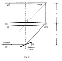
- FIG. 2a is a diagram of an embodiment of the invention in a reflection configuration.
- FIG. 2b is a diagram of an embodiment of the invention in a transmission configuration.
- FIG. 3 is a diagram of an embodiment of the invention using a THz wave as its imaging wave.
- FIG. 4 indicates the imaging area in the embodiment presented in Fig. 3 .
- FIG. 5a is a diagram of a steering mirror setup in one embodiment of the invention.
- FIG. 5b is a diagram of another steering mirror setup in one embodiment of the invention.
- FIG. 6a indicates parallel beam walking for two different mirrors at different sides of the focal point in Fig. 5b .
- FIG. 6b shows beam traces when the incident beam has a displacement to the focal point.
- FIG. 6c indicates returning beam spots from the incident one on the steering mirror.
- FIG. 7 is a diagram of one embodiment of the invention using three steering mirrors.
- FIG. 8a shows beam traces in the 3-mirror configuration.
- FIG. 8b shows the temporal variation when the steering mirror has offset to the focal point of the focusing lens.
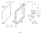
- FIG. 9 is a diagram of two cylindrical lenses in one embodiment of the invention.
- FIG. 10 is a diagram of one embodiment of the invention used in a pulsed THz system.
- FIG. 11 is a diagram of the control system of the embodiment shown in Fig. 10 .
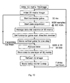
- FIG. 12 shows a logic flow chart of the imaging process in the embodiment shown in Fig. 10 .
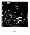
- FIG. 13 is a photo of one embodiment of the invention used in a pulsed THz system.
- FIG.14a shows THz field distribution in the image area at a fixed delay time.
- FIG. 14b shows THz amplitude distribution in image area.
- FIG. 14c is the distribution of THz pulses' peak timing in image area.
- FIG. 14d shows calibrated distribution of THz amplitude in the image area.
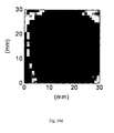
- FIG. 15a gives a THz wave image of a metallic razor blade recorded according to the contrast to the background.
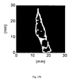
- FIG. 15b is a THz wave image of the same blade using THz pulses reflected from its surface.
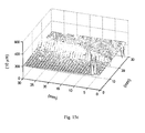
- FIG. 15c gives a topographic image of the blade.
- FIG. 16a compares THz waveforms with (dashed curve) and without (solid curve) target (a polyethylene pellet).
- FIG. 16b is a THz wave image of this pellet recorded according to the contrast to the background.
- FIG. 16c is a topographic image of the pellet using the time delay of transmitted THz pulses.
- FIG. 1 represents an exemplary embodiment of the present invention.
- a THz incident beam 10 is guided by a steering mirror 20 incident onto a focusing lens 30 and it is focused by the lens 30 onto the target 40.
- Rotating the mirror 20 scans the focal spot to different locations (101, 102, and 103 et. al.) on the target.
- the THz beam having interacted with the target (either transmission through or reflection from) will be collected and fed into a point detector.
- the image of the target will be created by rotating the steering mirror 20.
- the focusing lens 30 could be made using polyethylene, silicon, et. al.
- a curved mirror such as paraboloidal mirror can also be incorporated in replacement of the lens, with a proper adjustment of the target location.
- Fig. 2a shows an important embodiment of the present invention, where a collimated THz beam 10 is incident into the mirror-lens set and it intersects with the rotation axis of the steering mirror 20 at one focal point of the lens 30.
- the lens 30 focuses the beam normally onto its focal plane on the opposite side.
- the target 40 lies on the focal plane. Therefore, each spot on the target is a function of the incident angle. If the THz beam is specularly reflected by the target, which is mostly true as THz waves have long wavelength, for example up to at least a few tens of microns, the returning beam counter propagates with the input beam. As a result, the entire radiation transmitted from the source can be utilized to image the target.
- Fig. 3 is a diagram showing use of this embodiment with a THz wave source and detector.
- a THz wave transceiver 60 could be used to emit and receive THz waves.
- THz wave focusing optics such as a parabolic mirror 50 is used to collimate transmitted THz waves, and the same optics can be used to collect returning THz waves.
- Fig. 2a can also work in a transmission configuration as presented in Fig. 2b .
- a receiving mirror-lens set (20a and 30a) is placed on the other side of the target 40 and it is an image of the incident set (20 and 30).
- the steering mirror 20a at the receiving side acts as a slave of the incident steering mirror 20. Its rotation is synchronized with the incident mirror 20.
- the received THz beam after the steering mirror 20a will be collimated and maintain the same propagation direction at all rotation angles, and a fixed detector will be able to receive the THz beam transmitted through any spot on the target.
- the focusing lens which is identical to the collecting optics, can move along the optical axis, so that information to be imaged can be obtained at the surface or inside the target, if the target is sufficiently transparent.
- the wave to be imaged can be extended in its property beyond the reflection shown in this exemplary embodiment.
- the origin of the wave out of the target can be scattered in the specular direction, or diffracted or even refracted to the specular direction by the structure in or on the sample. Randomly distributed nano-structures on and inside the target can be an example of an arrangement where this is possible.
- the maximum image size is also limited by the size of the focusing lens and the size of the THz beam.
- the bigger solid circle shows the boundary of the focusing lens 30 and the smaller open circle 302 is the THz beam on the lens.
- the maximum offset of the THz beam on the focusing lens is presented in Fig. 4 . If the spanning angle is even bigger, part of the THz beam will be outside of the imaging lens.
- the dashed circle 301 indicates the maximum imaging area determined by the imaging lens and THz beam.
- ⁇ is wavelength of the imaging wave.
- Fig. 5a and Fig. 5b give two examples of the steering mirror scanning setup 20.
- one galvanometer 202 is used to drive the steering mirror 201. It steers the THz beam spanning one dimension and the entire setup (201, 202, and 203) is rotated about another axis 204 perpendicular to the first one. The cross point of these two axes is located at the focal point of the focusing lens 30 shown in Fig. 2 . 2D scanning can also be made using a configuration shown in Fig. 5b , where one galvanometer 202a scans the THz beam along one dimension and the other galvanometer 202b scans the THz beam along the perpendicular direction.
- the configuration shown in Fig. 5b is more compact and is freely controllable in either scanning dimension.
- the two-galvanometer configuration may introduce parallel beam walking into the beam scanning apparatus.
- the first mirror 201a (actually it is the image of the 1 st mirror 201 a in the 2 nd mirror 201b) and second mirror 201 b respectively.
- the THz beam is displaced from the focal point of the focusing lens, and its scanning ranges on the lens 30 are different when scanning the first mirror and the second mirror for the same angle.
- Fig. 6b shows beam traces of THz beams with a certain incident angle. If the incident THz beam (10a) passes through the focal spot of the focusing lens 30, the beam is bent by the lens 30 normally incident onto the target 40. The target then retro-reflects the incident beam. If the incident beam (10b) is away from the focal point with a displacement of H, the returning beam will be on the opposite side of the focal point with a counter propagation direction and will have the same displacement to the focal point. Consequently, the returning beam will be collected by the same focusing optics (such as 50 in Fig. 3 ) and focused to the detector at the same spot although there is parallel beam walking. As a result, the parallel beam walking will not mislead the returning beam.
- the incident THz beam (10a) passes through the focal spot of the focusing lens 30, the beam is bent by the lens 30 normally incident onto the target 40. The target then retro-reflects the incident beam. If the incident beam (10b) is away from the focal point with a displacement of H, the returning beam will be on the opposite side
- the maximum scanning angle is +/- 16.7°. In this case, if the distance between the 1 st and the 2 nd mirror is 25 mm, the maximum beam walking will be 8 mm.
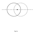
- Fig. 6c shows the overlap of these two beams.
- the solid circle represents the input beam, which can be considered as the aperture of the steering mirror.
- the dashed circle is the returning beam, which is symmetric with the input beam about the focal point shown as a solid spot in the figure. Because the center of the input beam is off from the focal point, part of the returning beam lies outside of the steering mirror. As a result the collection efficiency of the returning beam is reduced.
- a galvanometer setup with three galvanometers can be used to create 2D beam scanning and to compensate the parallel beam walking in the apparatus.
- An exemplary embodiment is presented in Fig. 7 .
- the incident beam 10a is scanned by the first steering mirror 20 1 a in horizontal direction (10b).
- a second steering mirror 20 1 b which rotates according to the first mirror 201 a, is used to maintain the beam spot on the third steering mirror 201c at the same location while the mirror 201 a is scanning.
- Rotation of mirror 201 a and 201 b results in the THz beam scanning in a horizontal direction starting from a single spot on mirror 201 c.
- the steering mirror 201c rotates in the vertical direction. Therefore, using three steering mirrors (201a, 201b and 201 c), the THz beam is scanned in 2D bending from a single point.
- Fig. 8a gives the relationship between rotation angles of the first steering mirror and the second steering mirror.
- the incident beam is guided into the steering mirror set at the point A, which is the rotation center of the 1 st mirror.
- the rotation center of the 2 nd mirror is at O.
- the input beam is steered following AO, and it will be reflected by the 2 nd mirror to the 3 rd mirror following OB, where B is located on the rotation axis of the 3 rd mirror.
- ⁇ which the incident beam changes from its original direction steered by the 1 st mirror, there is an angle of ⁇ .
- the parallel beam walking can be compensated using a three-galvanometer configuration.
- the beam path changing which must be taken into account, especially when the imaging process has fine temporal resolution, such as in pulsed THz wave imaging.
- This issue is the optical path variation, which results in a temporal variation in temporal resolved imaging, with beam scanning.
- Fig. 8b shows the optical path in the apparatus if the rotation center of the steering mirror has a displacement h to the focal point of the focusing lens.
- the maximum temporal variation for a 20 degree beam span is 5 mm (33 ps temporal variation).
- Temporal variation causes no effect in an imaging process with no temporal resolution, or with a temporal resolution much longer than the temporal variation.
- some imaging processes which have a fine temporal resolution, such as pulsed THz wave imaging, one needs to retrieve the imaging after recording images at all temporal positions, in order to compensate the temporal variation in scanning.
- Fig. 9 is a diagram of one embodiment of the present invention used to minimize both parallel beam walking and temporal variation with scanning in a two-galvanometer configuration.
- 2 cylindrical lenses 301 and 302 are used to replace the single focusing lens.
- One optic or optical set which has different focal length following two different axes, can also be used for this purpose.
- the exemplary embodiment described so far can be extended so that the all required optics can be translated laterally together. In this way, imaging of area-by-area is possible.
- the time for the translation can be utilized for data processing of the area imaged prior to the translation.
- M1 and M2 are two scanning mirrors (X-mirror 201a and Y-mirror 201b) driven by a pair of galvanometers.
- M1' is the image of M1 in M2 in the original direction.
- CL1 and CL2 are two cylindrical lenses.
- the focal length of each lens (301 and 302) equals half of the distance between the corresponding mirror (201a for 301, and 201b for 302) to the target 40.
- the distance between the target 40 to each of the cylindrical lens (301 or 302) is the focal length of the lens.
- CL1 and CL2 focus a collimated beam onto the target, and the lateral position of the focal spot is determined by the direction of the incident beam.
- Fig. 10 is a schematic diagram of a pulsed THz wave apparatus, which was used to verify the concept of the present invention.
- a femtosecond (fs) laser (Femtolite F-100) is used to generate THz pulses and to detect them.
- the fs laser beam is split into two arms, the pumping arm and probing arm, respectively.
- THz pulses are generated via a photoconductive switch 60a triggered by the pumping pulses.
- Transmitted THz beam is collimated using a parabolic mirror 50 and is guided into a double axis galvanometer set 20.
- THz beam output from the galvanometer set is focused using two cylindrical lenses 30 onto a target 40.
- the aperture of the galvanometer is 15 mm in diameter.
- the displacement between two mirrors of the galvanometer set is 25 mm.
- Focal lengths of the two cylindrical lenses are 57 mm and 44 mm respectively.
- the reflected THz beam is picked-up by a silicon beam splitter in the THz beam and part of the reflected THz beam was focused onto a (110) ZnTe crystal 60b, which is used as the sensor of THz pulses.
- the THz beam and the probing beam collinearly propagate through the ZnTe crystal, where the polarization of the probing beam is modified through an EO process.
- the THz field is recorded by a polarization sensitive balanced detection geometry afterward.
- Fig. 11 shows the concept of controlling geometry of the proof of concept system.
- a high speed digital/analog multifunctional card with 600 KS/s data acquisition rate is used to acquire data and to control the scanning system.
- Fig. 12 shows a logic flow chart of the pulsed THz wave imaging process.
- Fig. 13 is a photo of this system.
- Fig. 14a shows the distribution of THz field in the image area at a fixed delay time between pumping and probing pulses. The result was measured by using a metallic flat mirror as the target. Due to the temporal variation in scanning, the distribution of the THz field at a fixed timing shows ring structures like an interference pattern.
- Fig. 14b presents the distribution of THz amplitude (peak amplitude of THz waveform) in the image area. This figure gives a ratio of each pixel described as A 0 / A i , where A 0 is THz amplitude of the central pixel and A i indicates THz amplitude of the pixel whose index is i .
- Fig. 14c gives the temporal shift distribution in the image area comparing to the central pixel.
- THz field can be retrieved with images at all delay times.
- the retrieved THz field distribution is in Fig. 14d , which gives a uniform distribution except for those pixels very close to the edge.
- Figs. 15 show THz wave images of a metallic razor blade, which is mounted on top of the mirror. All images are recorded at a speed of 1 frame per second.
- Fig. 15a is an image recorded according to contrast to the background, which was caused due to the razor blade blocking THz radiation.
- Fig. 15b is an image of THz pulses reflected from the razor blade.
- Fig. 15c is a topographic image of the razor blade, which gives the thickness of the razor blade.
- THz wave imager was also used to image dielectric targets.
- Fig 16a shows THz waveforms when there was (dashed curve) or was not (solid curve) a polyethylene pellet placed on the top of the metallic mirror. THz pulses transmitted through the target show a displacement along the delay axis.
- Fig. 16b shows a THz wave image of the pellet according to its contrast to the background, and
- Fig. 16c is a topographic image recorded according to time delay of THz pulses transmitted through the pellet.
- embodiments of the invention may be utilize a frequency range of I GHz to 100 THz. Further, this technology can be applied to electromagnetic waves at other frequencies, sound, electron beams, et. al., which can be steered and focused, and can be used to image a target using this method.
Landscapes
- Physics & Mathematics (AREA)
- General Physics & Mathematics (AREA)
- Electromagnetism (AREA)
- Investigating Or Analysing Materials By Optical Means (AREA)
Abstract
Description
- This application claims priority from
US Provisional Application number 60/907,639 filed April 12, 2007 - This invention relates to imaging technology, and more particularly an imaging process using terahertz electro-magnetic waves. The invention is an apparatus designed for scanning and collecting for the imaging information.
- Electro-magnetic waves, in the frequency range located between infrared and microwave, are one of the latest developed areas of spectrum. This band is often referred to as the terahertz (THz) band. These waves are transparent for most non-polar dielectrics, such as plastic, paper, stone, wood, oil, smoke, et. al. This makes THz wave imaging an ideal tool as a complement to x-ray and ultrasound imaging in security inspection and quality control applications. Additionally, THz wave imaging provides spectroscopic information on the target, and it can be used to identify the target. THz wave imaging is safe to both the sample and the operator as THz photons have very low energy (meV), which will not ionize molecules.
- THz wave imaging technology such as described in
U.S. Patent No. 5,623,145 andU.S. Patent No. 5,710,430 to M. Nuss , demonstrated the capability of seeing through plastic and mapping metal electrodes underneath. Most THz wave imaging apparatuses developed since then use a raster scanning mode to image the target. THz radiation emitted from the source is focused on the target imaged, and is recorded using a point detector after interacting with the target through transmission or reflection. The target is imaged via scanning the target crossing the THz wave focal spot in an X-Y plane or alternatively scanning the imager in opposite directions. Raster scanning fully utilizes THz waves generated from the source and results in a high measurement dynamic range, which is especially important in the THz regime where lack of intense sources and sensitive detectors pose a problem. - Raster scanning an image requires linearly scanning either the target or the imager within the entire image area, which is not only time consuming but also inconvenient. 2D focal plane imaging, which uses a 2D extended detector (such as an electro-optical (EO) crystal) or a detector array (such as a microbolometer array) instead of a point detector to record the distribution of the THz field at the image plane, was developed to improve imaging speed. An example is reported in "Two-dimensional electro-optic imaging of THz beams," Appl, Phys. Lett., 69, 1026-1028 (1996) by Q. Wu et. al., where a single crystal EO sensor was employed as the extended THz wave sensor. An intense THz beam, which was extended illuminating the entire target, was generated using a femtosecond (fs) laser amplifier through an optical rectification or an optical switching process. The THz wave image of the target was created using an imaging lens and the EO crystal was placed at the image plane. An extended probing beam was used to read out the THz field distribution on the EO crystal, which was the THz wave image of the target.
- Detector arrays, and 2D focal plane imaging methods, have also been developed for cw THz radiation under certain circumstances. One example was reported in "Real-time, continuous-wave terahertz imaging by use of a microbolometer focal-plane array," Opt. Lett. 30, 2563-2565 (2005), by A.W. Lee et. al., where a microbolometer array, which was designed for middle infrared radiation, was demonstrated to have the capability to record 2D images at a high THz frequency (2.52 THz). Other examples include
U.S. Patent No. 6,242,740 to A. Luukanen et. al. , andU.S. Patent No. 6,943,742 to S. Holly. -
Prior art 2D focal plane THz wave imaging systems, however are only available under limited conditions. Especially, these detector arrays are only sensitive at limited frequency ranges. They also require a relatively more intense THz source than point detectors due to the low sensitivity of detector arrays and dilution of the THz radiation on multi pixels at one time. Alternative methods were therefore developed to improve imaging speed without using an extended detector or detector array. Prior artU.S. Patent No. 6,909,094 andU.S. Patent No. 6,909,095, to P. Tran et. al. , use a distributed waveguide technique to receive THz wave image at the image plane and using a point detector to receive signals from all pixels sequentially. "Terahertz wave reciprocal imaging," Appl. Phys. Lett. 88, 151107 (2006), by J. Xu et. al, reported using a source array rather than a detector array to present a focal plane image in a reciprocal way. These arts avoid using 2D detector arrays, which are not available or not ideal for THz waves, however there are still other challenges when using a waveguide array or a source array. -
U.S. Patent No. 6,815,683 to J. Federici adapted an interferometric imaging technique from the microwave regime to the THz regime. Using only a few detectors and without using an imaging lens, this technique promises to present large scale THz wave imaging without moving imager or target. On the other had, this art utilizes THz radiation in an inefficient way, as no collection optics is allowed in this technology. - Compared to arts using distributed detection or emission components, the raster scanning method is still the predominantly used imaging method for THz radiation because it provides higher measurement dynamic range, gives better image quality and is available for all kinds of THz wave sources and detectors.
- Efforts have also been taken to improve the speed of THz wave raster scanning image. An example was described in
WO 02/057750 by B. Cole et. al - The detectivity of THz waves currently available is not sufficient to utilize these waves for an imaging device in a comparable fashion to other well developed areas of wavelength ranges. Furthermore, the lack of a strong source to overcome the detectivity problem is also challenging. The immature source technology also leads to difficulties in manipulating the wave to be accommodated into other techniques. As a result, detection of scattered light out of a target to be imaged is not a practical method, due to the lack of strong source. Equally, realization of a modulation technology to enhance the detectivity of a weak source is not feasible due to immature technology surrounding the source. Speed of imaging is another important factor in considering an effective imaging system.
- Currently, no prior art is known for an imaging apparatus in the range of extended THz frequencies, e.g., 1 GHz ~ 100 THz, disclosing a concept for realization of practically usable sensitivity and speed. This disclosure addresses these two major points with an exemplary embodiment focusing on two dimensional raster scanning of an image by scanning the THz beam across each spot of the target using a wave in the frequency range of 10 GHz ~ 3 THz.
- The present invention is directed to an scanning image system, in particular a THz wave imaging system. Rastering a target to be imaged with a pulsed THz wave centered at ~ 1 THz is disclosed to be an exemplary embodiment, although the frequency range may be between about GHz and 100 THz. Some embodiments may utilize a frequency range of 1 GHz to about 10 THz. Other embodiments may utilize a frequency range of about I GHz to about 20 THz. Corresponding wavelengths may be up to at least a few tens of microns, for example about 20 microns. The THz source of the present THz wave imager could be generated coherently or incoherently.
Sources can be a THz pulse utilizing ultrafast optical rectification or an optical switch in combination with an ultrashort pulse laser. Furthermore, a cw THz electronic transmitter, or a THz wave laser, or even an incoherent thermal emitter can be incorporated within this disclosure. - On the other hand, in the detection scheme, a photo-conductive switch, electro-optic sample, bolometric detection, or other devices can be incorporated within the invention. For phase-sensitive detection, often called coherent detection, both pulsed and continuous wave can be combined within this disclosure to utilize the suppression of thermal noise in the detection technique. A time-domain point detector with relatively high response speed, for high speed imaging, is disclosed to be an exemplary embodiment.
- Instead of linearly scanning the target or the imager, a mirror/lens set is used for steering the THz beam across each spot of the target. The steering mirror set could be driven using a galvanometer (or a pair of galvanometers for 2D scanning), which supports a line scanning speed up to 300 Hz (up to 600 lines per second with a zigzag scanning mode). This speed is sufficient for a real time imaging application. Especially, the incident beam could be collimated and the steering mirror could rotate about two axes, whose crossing point locates at a focal point of the focusing lens. The target is located at the focal plane on the opposite side of the imaging lens and is normal to the optical axis of the lens. Under this condition, the THz beam will be retro-reflected by the target and full THz radiation will be utilized in the imaging process.
- The imaging wave can be obtained primarily by reflection or transmission. However, scattering or refraction arranged to a specular direction can be incorporated into the invention. Alternatively, the present invention could be used in a passive imaging configuration, where no incident THz radiation is required and the mirror/lens set is used to steer THz radiation emitted or reflected from an external source not included in the imaging system from each spot of the target to the point detector.
The spectral information carried by reflection, transmission, emission, refraction and scattering is analyzed by a time-domain measurement. -
FIG. 1 is a diagram of a first embodiment of the invention. -
FIG. 2a is a diagram of an embodiment of the invention in a reflection configuration. -
FIG. 2b is a diagram of an embodiment of the invention in a transmission configuration. -
FIG. 3 is a diagram of an embodiment of the invention using a THz wave as its imaging wave. -
FIG. 4 indicates the imaging area in the embodiment presented inFig. 3 . -
FIG. 5a is a diagram of a steering mirror setup in one embodiment of the invention. -
FIG. 5b is a diagram of another steering mirror setup in one embodiment of the invention. -
FIG. 6a indicates parallel beam walking for two different mirrors at different sides of the focal point inFig. 5b . -
FIG. 6b shows beam traces when the incident beam has a displacement to the focal point. -
FIG. 6c indicates returning beam spots from the incident one on the steering mirror. -
FIG. 7 is a diagram of one embodiment of the invention using three steering mirrors. -
FIG. 8a shows beam traces in the 3-mirror configuration. -
FIG. 8b shows the temporal variation when the steering mirror has offset to the focal point of the focusing lens. -
FIG. 9 is a diagram of two cylindrical lenses in one embodiment of the invention. -
FIG. 10 is a diagram of one embodiment of the invention used in a pulsed THz system. -
FIG. 11 is a diagram of the control system of the embodiment shown inFig. 10 . -
FIG. 12 shows a logic flow chart of the imaging process in the embodiment shown inFig. 10 . -
FIG. 13 . is a photo of one embodiment of the invention used in a pulsed THz system. -
FIG.14a shows THz field distribution in the image area at a fixed delay time. -
FIG. 14b shows THz amplitude distribution in image area. -
FIG. 14c is the distribution of THz pulses' peak timing in image area. -
FIG. 14d shows calibrated distribution of THz amplitude in the image area. -
FIG. 15a gives a THz wave image of a metallic razor blade recorded according to the contrast to the background. -
FIG. 15b is a THz wave image of the same blade using THz pulses reflected from its surface. -
FIG. 15c gives a topographic image of the blade. -
FIG. 16a compares THz waveforms with (dashed curve) and without (solid curve) target (a polyethylene pellet). -
FIG. 16b is a THz wave image of this pellet recorded according to the contrast to the background. -
FIG. 16c is a topographic image of the pellet using the time delay of transmitted THz pulses. -
FIG. 1 represents an exemplary embodiment of the present invention. ATHz incident beam 10 is guided by asteering mirror 20 incident onto a focusinglens 30 and it is focused by thelens 30 onto thetarget 40. Rotating themirror 20 scans the focal spot to different locations (101, 102, and 103 et. al.) on the target. The THz beam having interacted with the target (either transmission through or reflection from) will be collected and fed into a point detector. The image of the target will be created by rotating thesteering mirror 20. The focusinglens 30 could be made using polyethylene, silicon, et. al.
Furthermore, a curved mirror such as paraboloidal mirror can also be incorporated in replacement of the lens, with a proper adjustment of the target location. -
Fig. 2a shows an important embodiment of the present invention, where acollimated THz beam 10 is incident into the mirror-lens set and it intersects with the rotation axis of thesteering mirror 20 at one focal point of thelens 30. As acollimated THz beam 10 comes from its focal point, thelens 30 focuses the beam normally onto its focal plane on the opposite side. Thetarget 40 lies on the focal plane. Therefore, each spot on the target is a function of the incident angle. If the THz beam is specularly reflected by the target, which is mostly true as THz waves have long wavelength, for example up to at least a few tens of microns, the returning beam counter propagates with the input beam. As a result, the entire radiation transmitted from the source can be utilized to image the target.Fig. 3 is a diagram showing use of this embodiment with a THz wave source and detector. ATHz wave transceiver 60 could be used to emit and receive THz waves. THz wave focusing optics such as aparabolic mirror 50 is used to collimate transmitted THz waves, and the same optics can be used to collect returning THz waves. - The embodiment shown in
Fig. 2a can also work in a transmission configuration as presented inFig. 2b . InFig. 2b a receiving mirror-lens set (20a and 30a) is placed on the other side of thetarget 40 and it is an image of the incident set (20 and 30). Thesteering mirror 20a at the receiving side acts as a slave of theincident steering mirror 20. Its rotation is synchronized with theincident mirror 20. As a result, the received THz beam after thesteering mirror 20a will be collimated and maintain the same propagation direction at all rotation angles, and a fixed detector will be able to receive the THz beam transmitted through any spot on the target.
Another interesting concept is the measurement of the angular radiation distribution of radiation out of a point source if the incident light is replaced with the radiation out of the target itself.
Furthermore, the focusing lens, which is identical to the collecting optics, can move along the optical axis, so that information to be imaged can be obtained at the surface or inside the target, if the target is sufficiently transparent.
The wave to be imaged can be extended in its property beyond the reflection shown in this exemplary embodiment. As long as the geometry of the focusing and collecting optics together with the steering optics is fulfilled as described in earlier sections, the origin of the wave out of the target can be scattered in the specular direction, or diffracted or even refracted to the specular direction by the structure in or on the sample. Randomly distributed nano-structures on and inside the target can be an example of an arrangement where this is possible. - It should be noted that, all embodiments discussed above and hereafter can be easily modified for use in a passive imaging configuration. The simplest modification is just replacing the transmitter with a point receiver. Rotating the
steering mirror 20, THz radiation emitted (reflected) from each spot of thetarget 40 will be guided into the receiver sequentially. - The diameter of the imaging area in embodiments shown in
Fig. 2a andFig. 2b is:
lens 30 and α denotes the maximum beam spanning angle driven by thesteering mirror 20. In most cases, the THz beam spanning angle is two times the steering mirror's rotating angle. - On the other hand, the maximum image size is also limited by the size of the focusing lens and the size of the THz beam. In
Fig. 4 , the bigger solid circle shows the boundary of the focusinglens 30 and the smalleropen circle 302 is the THz beam on the lens. The maximum offset of the THz beam on the focusing lens is presented inFig. 4 . If the spanning angle is even bigger, part of the THz beam will be outside of the imaging lens. The dashedcircle 301 indicates the maximum imaging area determined by the imaging lens and THz beam. The diameter is:
where DL and DB are diameters of the focusinglens 30 and theTHz beam 302, respectively. - The spatial resolution of such an image is limited by the diffractive limitation of the THz beam:

where λ is wavelength of the imaging wave. To keep the same spatial resolution and scanning angle while obtaining a larger imaging area, one needs to scale up the size of the lens, its focal length, and the diameter of the THz beam on the lens. -
Fig. 5a andFig. 5b give two examples of the steeringmirror scanning setup 20. InFig. 5a , onegalvanometer 202 is used to drive thesteering mirror 201. It steers the THz beam spanning one dimension and the entire setup (201, 202, and 203) is rotated about anotheraxis 204 perpendicular to the first one. The cross point of these two axes is located at the focal point of the focusinglens 30 shown inFig. 2 . 2D scanning can also be made using a configuration shown inFig. 5b , where onegalvanometer 202a scans the THz beam along one dimension and theother galvanometer 202b scans the THz beam along the perpendicular direction. - The configuration shown in
Fig. 5b is more compact and is freely controllable in either scanning dimension. However it should be noted that the two-galvanometer configuration may introduce parallel beam walking into the beam scanning apparatus. As presented inFig. 6a , there are two rotation axes, which present thefirst mirror 201a (actually it is the image of the 1stmirror 201 a in the 2ndmirror 201b) andsecond mirror 201 b respectively. When setting the focal spot in the middle between the first and second mirrors, the THz beam is displaced from the focal point of the focusing lens, and its scanning ranges on thelens 30 are different when scanning the first mirror and the second mirror for the same angle. -
Fig. 6b shows beam traces of THz beams with a certain incident angle. If the incident THz beam (10a) passes through the focal spot of the focusinglens 30, the beam is bent by thelens 30 normally incident onto thetarget 40. The target then retro-reflects the incident beam. If the incident beam (10b) is away from the focal point with a displacement of H, the returning beam will be on the opposite side of the focal point with a counter propagation direction and will have the same displacement to the focal point. Consequently, the returning beam will be collected by the same focusing optics (such as 50 inFig. 3 ) and focused to the detector at the same spot although there is parallel beam walking. As a result, the parallel beam walking will not mislead the returning beam. If the image area is 30 mm in diameter and the focal length of the imaging lens is 50 mm, the maximum scanning angle is +/- 16.7°. In this case, if the distance between the 1st and the 2nd mirror is 25 mm, the maximum beam walking will be 8 mm. - Although parallel beam walking does not mislead the returning beam, it does reduce overlap between the returning beam and the input beam.
Fig. 6c shows the overlap of these two beams. The solid circle represents the input beam, which can be considered as the aperture of the steering mirror. The dashed circle is the returning beam, which is symmetric with the input beam about the focal point shown as a solid spot in the figure. Because the center of the input beam is off from the focal point, part of the returning beam lies outside of the steering mirror. As a result the collection efficiency of the returning beam is reduced. - A galvanometer setup with three galvanometers can be used to create 2D beam scanning and to compensate the parallel beam walking in the apparatus. An exemplary embodiment is presented in
Fig. 7 . Theincident beam 10a is scanned by thefirst steering mirror 20 1 a in horizontal direction (10b). Asecond steering mirror 20 1 b, which rotates according to thefirst mirror 201 a, is used to maintain the beam spot on thethird steering mirror 201c at the same location while themirror 201 a is scanning. Rotation ofmirror mirror 201 c. Thesteering mirror 201c rotates in the vertical direction. Therefore, using three steering mirrors (201a, 201b and 201 c), the THz beam is scanned in 2D bending from a single point. -
Fig. 8a gives the relationship between rotation angles of the first steering mirror and the second steering mirror. The incident beam is guided into the steering mirror set at the point A, which is the rotation center of the 1st mirror. The rotation center of the 2nd mirror is at O. When the 1st mirror is at its original position, the input beam is steered following AO, and it will be reflected by the 2nd mirror to the 3rd mirror following OB, where B is located on the rotation axis of the 3rd mirror. For any angle of φ, which the incident beam changes from its original direction steered by the 1st mirror, there is an angle of β. If the 2nd mirror rotates β, the incident beam follows the path of AO'B, and ends at the same point B on the 3rd mirror. Rotation of the 1st mirror and the 2nd mirror together results in a scanning angle ϕ of the output beam. β and ϕ as functions of φ are in Eq. 4.


- The parallel beam walking can be compensated using a three-galvanometer configuration. However there is another issue created by the beam path changing which must be taken into account, especially when the imaging process has fine temporal resolution, such as in pulsed THz wave imaging. This issue is the optical path variation, which results in a temporal variation in temporal resolved imaging, with beam scanning.
Fig. 8b shows the optical path in the apparatus if the rotation center of the steering mirror has a displacement h to the focal point of the focusing lens. Optical path variation as a function of the THz beam scanning angle is:
- Optical path as a function of rotation angle in three-galvanometer configuration can be resolved according to Fig. 8c, as:


- Temporal variation causes no effect in an imaging process with no temporal resolution, or with a temporal resolution much longer than the temporal variation. However for some imaging processes, which have a fine temporal resolution, such as pulsed THz wave imaging, one needs to retrieve the imaging after recording images at all temporal positions, in order to compensate the temporal variation in scanning.
Fig. 9 is a diagram of one embodiment of the present invention used to minimize both parallel beam walking and temporal variation with scanning in a two-galvanometer configuration. In this embodiment, 2cylindrical lenses
Overall, if an oversized target needs to be imaged, the exemplary embodiment described so far can be extended so that the all required optics can be translated laterally together. In this way, imaging of area-by-area is possible. The time for the translation can be utilized for data processing of the area imaged prior to the translation. - M1 and M2 are two scanning mirrors (
X-mirror 201a and Y-mirror 201b) driven by a pair of galvanometers. M1' is the image of M1 in M2 in the original direction. CL1 and CL2 are two cylindrical lenses. The focal length of each lens (301 and 302) equals half of the distance between the corresponding mirror (201a for 301, and 201b for 302) to thetarget 40. The distance between thetarget 40 to each of the cylindrical lens (301 or 302) is the focal length of the lens. CL1 and CL2 focus a collimated beam onto the target, and the lateral position of the focal spot is determined by the direction of the incident beam. - As presented in
Fig. 9 , when M1 is scanning and M2 is fixed or vice versa the focal spot scans along x or y axes on the target. The beam will be retro-reflected and no temporal shift will occur. When both M1 and M2 are scanning, however, the image of M1 moves with M2's scanning. This causes the beam bending position to leave the focal line of CL1 (FL1 inFig. 9 ). A detailed calculation of beam walking and temporal variation is complicated. Eq. 8a and Eq. 8b give approximate estimations of parallel beam walking and optical path variation as functions of the beam scanning angle:

-
Fig. 10 is a schematic diagram of a pulsed THz wave apparatus, which was used to verify the concept of the present invention. In this system, a femtosecond (fs) laser (Femtolite F-100) is used to generate THz pulses and to detect them. Firstly, the fs laser beam is split into two arms, the pumping arm and probing arm, respectively. THz pulses are generated via aphotoconductive switch 60a triggered by the pumping pulses. Transmitted THz beam is collimated using aparabolic mirror 50 and is guided into a double axis galvanometer set 20. THz beam output from the galvanometer set is focused using twocylindrical lenses 30 onto atarget 40. In one experiment, the aperture of the galvanometer is 15 mm in diameter. The displacement between two mirrors of the galvanometer set is 25 mm. Focal lengths of the two cylindrical lenses are 57 mm and 44 mm respectively. The reflected THz beam is picked-up by a silicon beam splitter in the THz beam and part of the reflected THz beam was focused onto a (110)ZnTe crystal 60b, which is used as the sensor of THz pulses. The THz beam and the probing beam collinearly propagate through the ZnTe crystal, where the polarization of the probing beam is modified through an EO process. The THz field is recorded by a polarization sensitive balanced detection geometry afterward. -
Fig. 11 shows the concept of controlling geometry of the proof of concept system. To have high speed imaging, a high speed digital/analog multifunctional card with 600 KS/s data acquisition rate is used to acquire data and to control the scanning system.Fig. 12 shows a logic flow chart of the pulsed THz wave imaging process.Fig. 13 is a photo of this system. -
Fig. 14a shows the distribution of THz field in the image area at a fixed delay time between pumping and probing pulses. The result was measured by using a metallic flat mirror as the target. Due to the temporal variation in scanning, the distribution of the THz field at a fixed timing shows ring structures like an interference pattern.Fig. 14b presents the distribution of THz amplitude (peak amplitude of THz waveform) in the image area. This figure gives a ratio of each pixel described as A0 /Ai , where A0 is THz amplitude of the central pixel and Ai indicates THz amplitude of the pixel whose index is i.Fig. 14c gives the temporal shift distribution in the image area comparing to the central pixel. Except for those pixels very close to the edge, the temporal variation in the entire range is about one THz wavelength. The distribution of THz field can be retrieved with images at all delay times. The retrieved THz field distribution is inFig. 14d , which gives a uniform distribution except for those pixels very close to the edge. -
Figs. 15 show THz wave images of a metallic razor blade, which is mounted on top of the mirror. All images are recorded at a speed of 1 frame per second.Fig. 15a is an image recorded according to contrast to the background, which was caused due to the razor blade blocking THz radiation.Fig. 15b is an image of THz pulses reflected from the razor blade.Fig. 15c is a topographic image of the razor blade, which gives the thickness of the razor blade. - THz wave imager was also used to image dielectric targets.
Fig 16a shows THz waveforms when there was (dashed curve) or was not (solid curve) a polyethylene pellet placed on the top of the metallic mirror. THz pulses transmitted through the target show a displacement along the delay axis.Fig. 16b shows a THz wave image of the pellet according to its contrast to the background, andFig. 16c is a topographic image recorded according to time delay of THz pulses transmitted through the pellet. - Although the above discussion uses THz waves as imaging waves, embodiments of the invention may be utilize a frequency range of I GHz to 100 THz. Further, this technology can be applied to electromagnetic waves at other frequencies, sound, electron beams, et. al., which can be steered and focused, and can be used to image a target using this method.
Claims (27)
- An imaging apparatus, comprising:an electro-magnetic wave source generating a continuous wave or pulsed output, generated coherently or incoherently,steering optics for the electro-magnetic wave,an optical converter converting an angular variation of incident beam into a lateral variation,focusing optics for focusing the electro-magnetic wave at or within a target to be imaged,collecting optics collecting the electro-magnetic wave leaving the target,an electro-magnetic wave detector detecting the said collected wave,wherein the frequency range of said electro-magnetic wave is between 1 GHz to 100 THz, and
wherein the steering optics provides angular variation of the wave beam onto the focusing optics, and
wherein the angular conversion occurs in the focal plane of a lens or curved mirror, and
wherein the target is located in the range of a focal plane of the focusing optics or of the collecting optics, and
wherein the wave to be imaged carries spectral information in reflection, transmission, or scattering, refraction or diffraction arranged to the specular direction. - An apparatus as in Claim 1 , wherein the target emits the wave and is the wave source.
- An apparatus as in Claim 1, wherein the wave source and detector are not in the form of a multiple element array or an independently operating group of elements.
- An apparatus as in claim 1, wherein the steering optics provides angular variation of an incident wave beam and comprises a single or multiple number of reflecting mirrors.
- An apparatus as in Claim 1, wherein the angular converter comprises a single or multiple number of lens or curved mirrors, or a combination of both.
- An apparatus as in Claim 1, wherein the focusing optics is a single or multiple number of lens or curved mirrors, or combination of both.
- An apparatus as in Claim 1, wherein the collecting optics is a single or multiple number of lens or curved mirrors, or combination of both.
- An apparatus as in Claim 6, 7 or 8, wherein the focusing and collecting optics is identical.
- An apparatus as in Claim 6, 7 or 8, wherein the focusing, collecting and angular converting is performed by the same device.
- An apparatus as in Claim 1, wherein the collecting and focusing optics is identical and the optics moves relative to the target along with the optical axis of the optics, so that imaging of the target in the direction of the optical axis is achievable.
- An apparatus as in Claim 1, wherein the steering, angular converting, focusing, and collecting optics can be moved, so that a large-sized target can be imaged area-by-area.
- An apparatus as in claim 1, wherein a beam splitter is used to pick up the wave out of the target..
- An apparatus as in claim 1, wherein the optics or optical system before the detector is a focusing optics, which is used to focus the collimated beam into a point detector.
- An apparatus as in claim 1, wherein the transmitted wave through the target is recorded for imaging.
- An apparatus as in claim 2, wherein angular distribution of radiation of a point source located in the target is recorded for imaging.
- An apparatus as in claim 1, wherein the steering optics comprises mirrors mounted on galvanometers or rotational mirrors, or a combination of both.
- An apparatus as in claim 1, wherein the focusing lens is two cylindrical lenses used to minimize parallel beam walking and the temporal variation in the imaging process.
- An apparatus as in claim 1, wherein the focusing lens is a single optic or an optical set, whose focal lengths along two different axes are different in order to minimize parallel beam walking and temporal variation in the imaging process.
- An apparatus as in claim 15, wherein the steering mirror set further comprises three galvanometers with three mirrors, first and second galvanometers and mirrors being used to scan the wave beam in one direction and a third galvanometer and mirror being used to scan the beam in another direction.
- An apparatus as in claim 1, wherein the steering mirror has a small displacement to the focal spot of the focusing or collecting lens.
- An apparatus as in claim 1, wherein the beam from the source is not collimated and adjustment is required to optimize the beam out of target to the detector.
- An apparatus as in claim 1, wherein steering mirrors are synchronized to each other , so that the beam after the steering optics keeps a fixed direction.
- An apparatus as in Claim 1, wherein phase sensitive coherent detection of the wave is used in the time domain.
- An apparatus as in Claim 22, wherein spectral imaging is achieved by the time domain measurement.
- An apparatus as in Claim 1, wherein the wave is generated by using a laser light source.
- An apparatus as in Claim 1, wherein the collected information of imaging is processed by controlling all active devices in the imaging system.
- An apparatus as in Claim 1, wherein said frequency range is up to about 20 THz.
Applications Claiming Priority (1)
| Application Number | Priority Date | Filing Date | Title |
|---|---|---|---|
| US90763907P | 2007-04-12 | 2007-04-12 |
Publications (2)
| Publication Number | Publication Date |
|---|---|
| EP1980817A2 true EP1980817A2 (en) | 2008-10-15 |
| EP1980817A3 EP1980817A3 (en) | 2010-05-12 |
Family
ID=39530634
Family Applications (1)
| Application Number | Title | Priority Date | Filing Date |
|---|---|---|---|
| EP08006455A Withdrawn EP1980817A3 (en) | 2007-04-12 | 2008-03-31 | Beam scanning imaging method and apparatus |
Country Status (3)
| Country | Link |
|---|---|
| US (1) | US7897924B2 (en) |
| EP (1) | EP1980817A3 (en) |
| JP (1) | JP5367298B2 (en) |
Cited By (8)
| Publication number | Priority date | Publication date | Assignee | Title |
|---|---|---|---|---|
| WO2010145831A1 (en) * | 2009-06-19 | 2010-12-23 | Smiths Heimann Gmbh | Method and device for detecting hidden objects by means of electromagnetic millimeter waves |
| CN103256893A (en) * | 2013-05-28 | 2013-08-21 | 中国石油大学(北京) | Gauge and method of measuring position and size of light spot in terahertz time and domain spectroscopy system |
| WO2015027994A1 (en) * | 2013-08-27 | 2015-03-05 | Inoex Gmbh | Measuring device for reflection measurements of test objects and method for measuring radiation reflected on test objects |
| CN106290227A (en) * | 2016-08-25 | 2017-01-04 | 成都曙光光纤网络有限责任公司 | A terahertz wave reflection imaging device and method |
| CN110764158A (en) * | 2018-07-27 | 2020-02-07 | 中国科学院电子学研究所 | Terahertz imaging system based on reflection-type frequency control beam scanning device |
| CN114166791A (en) * | 2021-08-12 | 2022-03-11 | 博微太赫兹信息科技有限公司 | Terahertz time-domain spectrum probe device for biomedical imaging and time-domain spectrometer |
| EP2863211B1 (en) * | 2012-06-18 | 2022-04-13 | Nipro Corporation | Device for detecting impurities in powder using terahertz pulse waves, and method for detecting impurities |
| ES2935007R1 (en) * | 2020-05-15 | 2024-03-27 | Helmut Fischer Gmbh Inst Fuer Elektronik Und Messtechnik | Device to emit and/or receive terahertz radiation and control installation thereof |
Families Citing this family (25)
| Publication number | Priority date | Publication date | Assignee | Title |
|---|---|---|---|---|
| US9029775B2 (en) | 2008-05-19 | 2015-05-12 | Joseph R. Demers | Terahertz frequency domain spectrometer with phase modulation of source laser beam |
| CN102012562B (en) * | 2010-09-29 | 2012-05-16 | 首都师范大学 | A terahertz wave scanning method and system |
| GB2499159B (en) * | 2010-10-22 | 2015-04-15 | Neptec Design Group Ltd | Wide angle bistatic scanning optical ranging sensor |
| US20130146770A1 (en) * | 2011-12-08 | 2013-06-13 | Electronics And Telecommunications Research Institute | Terahertz continuous wave system and method of obtaining three-dimensional image thereof |
| KR101377566B1 (en) | 2011-12-20 | 2014-03-26 | 한국과학기술원 | High speed Terahertz TDS image processing method using high speed scanning apparatus |
| US9568422B2 (en) * | 2012-12-17 | 2017-02-14 | Advantest Corporation | Light beam incident device and reflected light measurement device |
| US20140198195A1 (en) * | 2013-01-17 | 2014-07-17 | Electronics And Telecommunications Research Institute | Terahertz health checker |
| US9400214B1 (en) | 2013-03-15 | 2016-07-26 | Joseph R. Demers | Terahertz frequency domain spectrometer with a single photoconductive element for terahertz signal generation and detection |
| US9103715B1 (en) | 2013-03-15 | 2015-08-11 | Joseph R. Demers | Terahertz spectrometer phase modulator control using second harmonic nulling |
| WO2015051661A1 (en) * | 2013-10-09 | 2015-04-16 | 北京大学口腔医学院 | Numerical control laser automatic tooth preparation method and device therefor, and tooth locator |
| US9404853B1 (en) | 2014-04-25 | 2016-08-02 | Joseph R. Demers | Terahertz spectrometer with phase modulation |
| US9086374B1 (en) | 2014-04-25 | 2015-07-21 | Joseph R. Demers | Terahertz spectrometer with phase modulation and method |
| US9995627B2 (en) * | 2014-07-31 | 2018-06-12 | Smiths Detection Inc. | Raster optic device for optical hyper spectral scanning |
| US9239264B1 (en) | 2014-09-18 | 2016-01-19 | Joseph R. Demers | Transceiver method and apparatus having phase modulation and common mode phase drift rejection |
| US9429473B2 (en) | 2014-10-16 | 2016-08-30 | Joseph R. Demers | Terahertz spectrometer and method for reducing photomixing interference pattern |
| KR101712890B1 (en) * | 2015-10-13 | 2017-03-08 | 한국표준과학연구원 | High-speed 3D imaging system using continuous-wave THz beam scan |
| CN106506996B (en) * | 2016-11-11 | 2019-03-08 | 山东大学 | A kind of short-wave infrared imaging system and its working method based on linear array laser illumination |
| ES2933508T3 (en) * | 2017-01-19 | 2023-02-09 | Novartis Ag | Method and apparatus for scanning by optical coherence tomography |
| FR3069333B1 (en) * | 2017-07-24 | 2021-05-14 | Terahertz Waves Tech | POINT VALUE CAPTURE SYSTEM TO CONSTITUTE AN IMAGE WITH TERAHERTZ RADIATION |
| KR102044388B1 (en) * | 2018-02-07 | 2019-11-13 | 아이오솔루션(주) | Apparatus for sacanning with mirror |
| US11391822B2 (en) | 2018-11-30 | 2022-07-19 | Seagate Technology Llc | Rotating pyramidal mirror |
| CN109708757B (en) * | 2018-12-11 | 2022-02-08 | 南京邮电大学 | Imaging spectrometer and high spatial resolution spectral imaging method based on scattering effect |
| US12146790B2 (en) | 2019-03-11 | 2024-11-19 | The Research Foundation For The State University Of New York | Terahertz three-dimensional spectral scanner apparatus and method of using same |
| DE102023101125A1 (en) | 2023-01-18 | 2024-07-18 | Helmut Fischer GmbH Institut für Elektronik und Messtechnik | Measuring device and positioning device and method for relative positioning of the measuring device with a THz device |
| JP7584824B1 (en) * | 2023-10-04 | 2024-11-18 | 株式会社 システムスクエア | Inspection Equipment |
Citations (7)
| Publication number | Priority date | Publication date | Assignee | Title |
|---|---|---|---|---|
| US5623145A (en) | 1995-02-15 | 1997-04-22 | Lucent Technologies Inc. | Method and apparatus for terahertz imaging |
| US5710430A (en) | 1995-02-15 | 1998-01-20 | Lucent Technologies Inc. | Method and apparatus for terahertz imaging |
| US6242740B1 (en) | 1997-09-16 | 2001-06-05 | Metorex International Oy | Imaging system functioning on submillimeter waves |
| WO2002057750A2 (en) | 2001-01-16 | 2002-07-25 | Teraview Limited | Apparatus and method for investigating a sample |
| US6815683B2 (en) | 2002-05-31 | 2004-11-09 | New Jersey Institute Of Technology | Terahertz imaging system and method |
| US6909095B2 (en) | 2003-02-12 | 2005-06-21 | Philip Morris Usa Inc. | System and method for terahertz imaging using a single terahertz detector |
| US6943742B2 (en) | 2004-02-16 | 2005-09-13 | The Boeing Company | Focal plane array for THz imager and associated methods |
Family Cites Families (22)
| Publication number | Priority date | Publication date | Assignee | Title |
|---|---|---|---|---|
| JPS5599049A (en) * | 1979-01-24 | 1980-07-28 | Toshiba Corp | Defect detector |
| US4733609A (en) * | 1987-04-03 | 1988-03-29 | Digital Signal Corporation | Laser proximity sensor |
| JP2709928B2 (en) * | 1987-12-23 | 1998-02-04 | 旭光学工業株式会社 | 2D scanning device |
| US5048904A (en) | 1990-07-06 | 1991-09-17 | General Scanning, Inc. | Two-mirror scanner with pincushion error correction |
| US5168386A (en) | 1990-10-22 | 1992-12-01 | Tencor Instruments | Flat field telecentric scanner |
| US5237444A (en) | 1992-06-26 | 1993-08-17 | General Scanning, Inc. | Optical scanning system |
| JP2001091848A (en) * | 1999-09-27 | 2001-04-06 | Nikon Corp | Scanning optical microscope |
| GB2372930B (en) * | 2000-03-03 | 2003-03-19 | Teraview Ltd | Apparatus and method for investigating a sample |
| KR100990300B1 (en) | 2001-06-13 | 2010-10-26 | 오르보테크 엘티디. | Energy delivery systems |
| US6999487B2 (en) * | 2001-10-05 | 2006-02-14 | Xerox Corporation | Terahertz generation processes and imaging process thereof |
| US6977379B2 (en) * | 2002-05-10 | 2005-12-20 | Rensselaer Polytechnic Institute | T-ray Microscope |
| GB0220755D0 (en) * | 2002-09-06 | 2002-10-16 | Univ Cambridge Tech | Terahertz spectroscopy |
| US7274451B2 (en) * | 2003-09-19 | 2007-09-25 | The Regents Of The University Of California | Optical beam translation device and method utilizing a pivoting optical fiber |
| JP2005101401A (en) * | 2003-09-26 | 2005-04-14 | Kansai Electric Power Co Inc:The | Terahertz electromagnetic wave generating device |
| US7238913B2 (en) | 2003-10-17 | 2007-07-03 | Gsi Group Corporation | Flexible scan field |
| US7643869B1 (en) * | 2004-03-17 | 2010-01-05 | Dabiri Ali E | Apparatus for non-invasive cancerous tissue diagnosis and tomography using terahertz imaging |
| GB2414294B (en) * | 2004-05-20 | 2006-08-02 | Teraview Ltd | Apparatus and method for investigating a sample |
| EP1749201A1 (en) * | 2004-05-26 | 2007-02-07 | Picometrix, LLC | Terahertz imaging in reflection and transmission mode for luggage and personnel inspection |
| US7355800B2 (en) * | 2005-02-07 | 2008-04-08 | Coherent, Inc. | Apparatus for projecting a line of light from a diode-laser array |
| JP2006308426A (en) * | 2005-04-28 | 2006-11-09 | Tochigi Nikon Corp | Terahertz measuring device |
| JP4975983B2 (en) | 2005-06-29 | 2012-07-11 | 株式会社リコー | Optical scanning device, multi-beam optical scanning device, and image forming apparatus |
| JP4892719B2 (en) * | 2005-08-24 | 2012-03-07 | 国立大学法人大阪大学 | Fault measurement device and fault measurement method |
-
2008
- 2008-03-25 US US12/055,063 patent/US7897924B2/en not_active Expired - Fee Related
- 2008-03-31 EP EP08006455A patent/EP1980817A3/en not_active Withdrawn
- 2008-04-11 JP JP2008103800A patent/JP5367298B2/en not_active Expired - Fee Related
Patent Citations (8)
| Publication number | Priority date | Publication date | Assignee | Title |
|---|---|---|---|---|
| US5623145A (en) | 1995-02-15 | 1997-04-22 | Lucent Technologies Inc. | Method and apparatus for terahertz imaging |
| US5710430A (en) | 1995-02-15 | 1998-01-20 | Lucent Technologies Inc. | Method and apparatus for terahertz imaging |
| US6242740B1 (en) | 1997-09-16 | 2001-06-05 | Metorex International Oy | Imaging system functioning on submillimeter waves |
| WO2002057750A2 (en) | 2001-01-16 | 2002-07-25 | Teraview Limited | Apparatus and method for investigating a sample |
| US6815683B2 (en) | 2002-05-31 | 2004-11-09 | New Jersey Institute Of Technology | Terahertz imaging system and method |
| US6909095B2 (en) | 2003-02-12 | 2005-06-21 | Philip Morris Usa Inc. | System and method for terahertz imaging using a single terahertz detector |
| US6909094B2 (en) | 2003-02-12 | 2005-06-21 | Philip Norris Usa Inc. | System and method for terahertz imaging using a single terahertz detector |
| US6943742B2 (en) | 2004-02-16 | 2005-09-13 | The Boeing Company | Focal plane array for THz imager and associated methods |
Non-Patent Citations (3)
| Title |
|---|
| "Terahertz wave reciprocal imaging", APPL. PHYS. LETT., vol. 88, 2006, pages 151107 |
| A.W. LEE: "Real-time, continuous-wave terahertz imaging by use of a microbolometer focal-plane array", OPT. LETT., vol. 30, 2005, pages 2563 - 2565 |
| Q. WU: "Two-dimensional electro-optic imaging of THz beams", APPL, PHYS. LETT., vol. 69, 1996, pages 1026 - 1028 |
Cited By (15)
| Publication number | Priority date | Publication date | Assignee | Title |
|---|---|---|---|---|
| CN102803931A (en) * | 2009-06-19 | 2012-11-28 | 史密斯海曼有限公司 | Method And Device For Detecting Hidden Objects By Means Of Electromagnetic Millimeter Waves |
| US8624772B2 (en) | 2009-06-19 | 2014-01-07 | Smiths Heimann Gmbh | Method and device for detecting hidden objects by means of electromagnetic millimeter waves |
| WO2010145831A1 (en) * | 2009-06-19 | 2010-12-23 | Smiths Heimann Gmbh | Method and device for detecting hidden objects by means of electromagnetic millimeter waves |
| EP2863211B1 (en) * | 2012-06-18 | 2022-04-13 | Nipro Corporation | Device for detecting impurities in powder using terahertz pulse waves, and method for detecting impurities |
| CN103256893A (en) * | 2013-05-28 | 2013-08-21 | 中国石油大学(北京) | Gauge and method of measuring position and size of light spot in terahertz time and domain spectroscopy system |
| CN103256893B (en) * | 2013-05-28 | 2015-07-08 | 中国石油大学(北京) | Gauge and method of measuring position and size of light spot in terahertz time and domain spectroscopy system |
| WO2015027994A1 (en) * | 2013-08-27 | 2015-03-05 | Inoex Gmbh | Measuring device for reflection measurements of test objects and method for measuring radiation reflected on test objects |
| US9791263B2 (en) | 2013-08-27 | 2017-10-17 | Inoex Gmbh | Measuring device for reflection measurements of test objects and method for measuring radiation reflected by test objects |
| CN106290227A (en) * | 2016-08-25 | 2017-01-04 | 成都曙光光纤网络有限责任公司 | A terahertz wave reflection imaging device and method |
| CN106290227B (en) * | 2016-08-25 | 2020-06-02 | 成都曙光光纤网络有限责任公司 | Terahertz wave reflection imaging device and method |
| CN110764158A (en) * | 2018-07-27 | 2020-02-07 | 中国科学院电子学研究所 | Terahertz imaging system based on reflection-type frequency control beam scanning device |
| CN110764158B (en) * | 2018-07-27 | 2022-11-22 | 中国科学院电子学研究所 | Terahertz imaging system based on reflective frequency-controlled beam scanning device |
| ES2935007R1 (en) * | 2020-05-15 | 2024-03-27 | Helmut Fischer Gmbh Inst Fuer Elektronik Und Messtechnik | Device to emit and/or receive terahertz radiation and control installation thereof |
| CN114166791A (en) * | 2021-08-12 | 2022-03-11 | 博微太赫兹信息科技有限公司 | Terahertz time-domain spectrum probe device for biomedical imaging and time-domain spectrometer |
| CN114166791B (en) * | 2021-08-12 | 2024-03-19 | 博微太赫兹信息科技有限公司 | Terahertz time-domain spectrum probe device for biomedical imaging and time-domain spectrometer |
Also Published As
| Publication number | Publication date |
|---|---|
| US7897924B2 (en) | 2011-03-01 |
| US20080251720A1 (en) | 2008-10-16 |
| JP2009008658A (en) | 2009-01-15 |
| JP5367298B2 (en) | 2013-12-11 |
| EP1980817A3 (en) | 2010-05-12 |
Similar Documents
| Publication | Publication Date | Title |
|---|---|---|
| US7897924B2 (en) | Beam scanning imaging method and apparatus | |
| US8373126B2 (en) | Apparatus and method for investigating a sample | |
| JP4773839B2 (en) | Detection device for detecting information of an object | |
| US6605808B2 (en) | Diagnostic apparatus using terahertz radiation | |
| US6977379B2 (en) | T-ray Microscope | |
| JP5209364B2 (en) | Terahertz beam scanning apparatus and method | |
| US9204063B2 (en) | Electromagnetic wave imaging apparatus | |
| CN104677497B (en) | Detection device and method for properties of terahertz waves | |
| JP2009210421A (en) | Terahertz spectrometer | |
| CN106290227B (en) | Terahertz wave reflection imaging device and method | |
| CN106169688A (en) | High speed based on tuned laser, wide-angle beam scanning method and device | |
| WO2017013759A1 (en) | Far-infrared spectroscopy device | |
| JP5067754B2 (en) | Near-field microscope and its spectroscopic / image acquisition method | |
| EP2980561A1 (en) | Imaging system | |
| JP5502564B2 (en) | Electromagnetic wave detection device | |
| CN220690787U (en) | Detection and measurement microscopic system based on three-mirror closed-loop scanning confocal | |
| KR20170049904A (en) | Module for detecting electromagnetic wave and, apparatus for detecting transmission of electromagnetic wave including adjacent detector | |
| KR102069299B1 (en) | High efficiehcy transmission image object inspection module and object inspection apparatus | |
| RU2540451C1 (en) | Laser location system | |
| US7528940B2 (en) | System and method for inspecting an object using an acousto-optic device | |
| JP6720383B2 (en) | Far infrared spectrometer | |
| JP5700527B2 (en) | Analysis apparatus and analysis method | |
| JP2021021933A (en) | Optical device | |
| KR101698910B1 (en) | Detection probe and probe-type detection apparatus | |
| JP2019074542A (en) | Acquisition apparatus |
Legal Events
| Date | Code | Title | Description |
|---|---|---|---|
| PUAI | Public reference made under article 153(3) epc to a published international application that has entered the european phase |
Free format text: ORIGINAL CODE: 0009012 |
|
| AK | Designated contracting states |
Kind code of ref document: A2 Designated state(s): AT BE BG CH CY CZ DE DK EE ES FI FR GB GR HR HU IE IS IT LI LT LU LV MC MT NL NO PL PT RO SE SI SK TR |
|
| AX | Request for extension of the european patent |
Extension state: AL BA MK RS |
|
| PUAL | Search report despatched |
Free format text: ORIGINAL CODE: 0009013 |
|
| RIC1 | Information provided on ipc code assigned before grant |
Ipc: G01B 15/04 20060101ALI20100331BHEP Ipc: G02B 27/00 20060101ALI20100331BHEP Ipc: G01B 11/24 20060101AFI20080627BHEP |
|
| AK | Designated contracting states |
Kind code of ref document: A3 Designated state(s): AT BE BG CH CY CZ DE DK EE ES FI FR GB GR HR HU IE IS IT LI LT LU LV MC MT NL NO PL PT RO SE SI SK TR |
|
| AX | Request for extension of the european patent |
Extension state: AL BA MK RS |
|
| 17P | Request for examination filed |
Effective date: 20101029 |
|
| AKX | Designation fees paid |
Designated state(s): DE FR GB |
|
| 17Q | First examination report despatched |
Effective date: 20130516 |
|
| STAA | Information on the status of an ep patent application or granted ep patent |
Free format text: STATUS: THE APPLICATION IS DEEMED TO BE WITHDRAWN |
|
| 18D | Application deemed to be withdrawn |
Effective date: 20151218 |