EP1980683A2 - Panel, in particular floor panel - Google Patents
Panel, in particular floor panel Download PDFInfo
- Publication number
- EP1980683A2 EP1980683A2 EP08007084A EP08007084A EP1980683A2 EP 1980683 A2 EP1980683 A2 EP 1980683A2 EP 08007084 A EP08007084 A EP 08007084A EP 08007084 A EP08007084 A EP 08007084A EP 1980683 A2 EP1980683 A2 EP 1980683A2
- Authority
- EP
- European Patent Office
- Prior art keywords
- spring element
- core
- spring
- panel according
- side edge
- Prior art date
- Legal status (The legal status is an assumption and is not a legal conclusion. Google has not performed a legal analysis and makes no representation as to the accuracy of the status listed.)
- Granted
Links
Images


Classifications
-
- E—FIXED CONSTRUCTIONS
- E04—BUILDING
- E04F—FINISHING WORK ON BUILDINGS, e.g. STAIRS, FLOORS
- E04F15/00—Flooring
- E04F15/02—Flooring or floor layers composed of a number of similar elements
-
- E—FIXED CONSTRUCTIONS
- E04—BUILDING
- E04F—FINISHING WORK ON BUILDINGS, e.g. STAIRS, FLOORS
- E04F15/00—Flooring
- E04F15/02—Flooring or floor layers composed of a number of similar elements
- E04F15/04—Flooring or floor layers composed of a number of similar elements only of wood or with a top layer of wood, e.g. with wooden or metal connecting members
-
- E—FIXED CONSTRUCTIONS
- E04—BUILDING
- E04F—FINISHING WORK ON BUILDINGS, e.g. STAIRS, FLOORS
- E04F2201/00—Joining sheets or plates or panels
- E04F2201/01—Joining sheets, plates or panels with edges in abutting relationship
- E04F2201/0107—Joining sheets, plates or panels with edges in abutting relationship by moving the sheets, plates or panels substantially in their own plane, perpendicular to the abutting edges
- E04F2201/0115—Joining sheets, plates or panels with edges in abutting relationship by moving the sheets, plates or panels substantially in their own plane, perpendicular to the abutting edges with snap action of the edge connectors
-
- E—FIXED CONSTRUCTIONS
- E04—BUILDING
- E04F—FINISHING WORK ON BUILDINGS, e.g. STAIRS, FLOORS
- E04F2201/00—Joining sheets or plates or panels
- E04F2201/01—Joining sheets, plates or panels with edges in abutting relationship
- E04F2201/0138—Joining sheets, plates or panels with edges in abutting relationship by moving the sheets, plates or panels perpendicular to the main plane
-
- E—FIXED CONSTRUCTIONS
- E04—BUILDING
- E04F—FINISHING WORK ON BUILDINGS, e.g. STAIRS, FLOORS
- E04F2201/00—Joining sheets or plates or panels
- E04F2201/02—Non-undercut connections, e.g. tongue and groove connections
Definitions
- the invention relates to a panel, in particular floor panel, with a core of wood material or wood-plastic mixture, an upper side and a lower side having at least one side edge of a spring and on the opposite side edge corresponding to the spring groove, and two identical trained panels are interconnected and lockable by a substantially horizontal joining movement in the horizontal and vertical directions, wherein the lock in the horizontal direction by at least one vertically movable, cooperating with the spring spring element is effected, which in the joining movement behind a in a snap locking edge extending from the horizontal direction snaps.
- Such a panel is for example from the WO 2004/085765 A1 known.
- This realized in this panel type of locking is preferably provided on the longitudinal side of floor panels. But it can also be provided on the transverse side or both on the transverse side and on the longitudinal side.
- the V-shaped spring element is made of plastic and is inserted in a vertical, provided in the top of the spring groove over the longitudinal side of the side edge.
- On the upper lip formed on the opposite side edge groove is provided an undercut, which cooperates with the spring lip of the spring element. When the two panels are pushed together horizontally, the spring lip abuts the upper lip of the groove and is compressed.
- the spring lip Upon further insertion of the spring into the groove, the spring lip eventually comes into coincidence with the undercut formed in the upper lip, snaps back in the vertical direction and snaps into the undercut, whereby the locking is effected in the horizontal direction. In the vertical direction, the locking takes place by the spring received in the groove of the other panel.
- the locking element is designed as a separate component, resulting in additional expenses.
- the production of the locking element is technologically conditioned spatially separated from the panels, so that an integration in the continuous manufacturing process, especially for floor panels, rather not possible. Due to the different materials, wood-based material on the one hand and plastic on the other hand, the alignment of manufacturing tolerances from two separate manufacturing processes is complex and cost-intensive. Since the lock would be ineffective in the horizontal direction in the absence of locking element, this must also be secured against falling out of the introduced in the spring vertical groove in the further manufacturing process and during transport. This backup is expensive. Alternatively, the locking element could be made available to the consumer separately.
- the floor panels in question are moved by do-it-yourselfers, so that in principle the possibility exists due to lack of experience that the required number of locking elements is initially misjudged and they are not procured in sufficient quantity to interpret a room completely.
- the handyman makes mistakes when inserting the spring element, with the result that the locking is not exactly possible and the bond dissolves over time, which is then wrongly attributed by the consumer to the quality supplied by the manufacturer.
- a generic floor panel is characterized in that the spring element is integrally formed out of the core.
- This design drastically simplifies production. The adjustment of the tolerances of different components is eliminated. Manufacturing times and costs are reduced because it is not necessary to bring different components together and hold them together. The end user is also ensured that no components are missing and in such a case then could not be further worked.
- This profiling is preferably provided on the transverse side of panels, which have already been connected to the longitudinal side, for example by angling and then connected by displacement along the longitudinal side to each other at the transverse side.
- the spring element may be formed on the spring or on the lower lip of the groove.
- the at least one spring element in the direction of its side edge and in the direction of the opposite side edge opposite the core is free and connected to at least one, in particular preferably at its two ends to the core. Due to the size of the effective connection of the spring element with the core, the spring elasticity can be adjusted.
- the exposure of the spring element is preferably carried out by means of two substantially vertical slots, which may extend parallel to each other.
- the width of the slots not only determines the strength of the connection of the spring element to the core material, but by choosing the width of the vertical slot, which is closest to the middle of the panel, the position of a stop in the horizontal direction for the spring element can be created so that it is safely protected against overstretching.
- the stability of the connection is increased by limiting the free path in the longitudinal direction of the spring element.
- the distance between the individual spring elements can be chosen more or less large. The smaller the distance, the larger the effective area is, of course, with the is locked so that the transferable forces in the vertical direction are correspondingly high.
- each two opposite side edges also mutually corresponding profilings may be provided so that two identically formed panels are connected and locked together by a substantially vertical joining movement in the horizontal and vertical directions, wherein the locking in the vertical direction by at least one in the horizontal direction movable spring element is effected, which snaps in the joining movement behind a substantially horizontally extending locking edge.
- this spring element can be integrally formed out of the core.
- the last-described type of locking is preferably then provided on the transverse side of the panels, if the connection on the longitudinal side by the first described profiling, which is provided instead of the transverse sides on the longitudinal sides, not by a pure horizontal joining movement, but the Panels are swung into each other by the new panel to create angled at an already laid panel, the spring inserted into the groove and then the new panel is lowered to the subfloor.
- the at least one spring element in the direction of the top and in the direction of the opposite side edge with respect to the core will be free and connected in the direction of its side edge at least one of its two ends to the core.
- the spring element is particularly preferably exposed by means of a substantially horizontal slot and a substantially vertical slot with respect to the core.
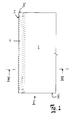
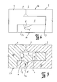
- the panels 1, 2 and 1a, 2a are identical. On one side edge I, la they are formed with a spring 6, 6a and on the opposite side edge II, IIa with a groove 3, 3a.
- the groove 3, 3a has a lower lip 4, 4a and an unspecified upper lip.
- the core 37 is made of wood material or a wood material-plastic mixture.
- FIGS. 2 to 4 and 2a to 4a illustrated embodiments essentially correspond.
- the panels 1a, 2a have opposite the panels 1, 2 on a projecting beyond the upper lip 4 lower lip 4a. Otherwise, the panels are similarly formed.
- the position numbers therefore only receive the suffix a.
- the outstanding in the direction of the top 16 spring element 5, 5a is arranged, via its two ends 12, 13 with the core 37 of the panels 1, 2; 1a, 2a is connected.
- the spring element 5, 5a separated by the vertical slot 8, 8a.
- the inner wall 8 ' which forms on the core 37 as a result of the slot 8, 8a, serves as a stop in the horizontal direction for the spring element 5, 5a, so that it is protected in the horizontal direction against overstretching.
- the top 18 of the spring element 5, 5a is chamfered and increases in the direction of the groove bottom 3 '.
- an undercut 6 ' is provided, whose inner contour is substantially to the outer contour of the Spring element 5, 5a corresponds. If two panels 1, 2a; 1a, 2a interconnected by shifting in the horizontal direction H, the spring 6, 6a of the panel 1, 1a dives into the groove 3, 3a of the panel 2, 2a.
- the spring element 5, 5a comes with its oblique upper side to the underside of the spring 6, 6a and is spring-down in the vertical direction V.
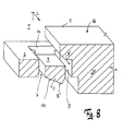
- the spring element 5 is formed on the spring 6 by two substantially extending in the vertical direction V slots 7, 8 and a running in the horizontal direction H slot 9 are introduced, so that the spring element 5 is exposed to the core and only with its two ends 14, 15 is connected to the core material.
- FIG. 8 can recognize the running in the horizontal direction slot 9 over the length L of the side edge I can be performed continuously.
- the parallel slots 7, 8 terminate in a plane below the upper side 16.
- the lower edge 5 'of the spring element 5 is chamfered and falls, as FIG. 8 indicates in the direction of the middle of the panel.
- the lower lip 4 is provided with an undercut 4 ', the inner contour of which substantially corresponds to the outer contour of the spring element 5.
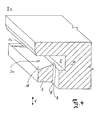
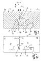
- FIGS. 9 and 10 show the connection of two panels 21, 22 on the transverse side.
- the core 37 consists of wood-based material or a wood-plastic mixture.
- the spring element 23 is formed, which was produced by milling the core 37 by milling a horizontal slot 31 and a substantially vertical slot 30 was milled.
- the side edges III, IV have the length I.
- the spring element 23 is connected at its ends to the core material. The exposure of the spring element 23 from the core 37 takes place exclusively through the slots 30, 31.
- the outer edge 23 c of the spring element 23 is inclined relative to the top 16 of the panel 22 at an angle.
- the vertical surfaces of the side edges III, IV are processed so that in the region of the top 16 contact surfaces 35, 36 form.
- the panel 21 is provided with a groove 29 extending substantially in the horizontal direction H, the upper side wall of which forms a substantially horizontally extending locking edge 24.
- the groove bottom of the groove 29 extends parallel to the outer edge 23 c of the spring element 23, which facilitates the production of the groove 29.
- it could be designed strictly in the vertical direction V or with an angle deviating from the angle of the outer edge 23c of the spring element 23.
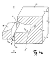
- the profiling of the hook elements 40, 41 is selected so that a bias voltage is generated in the joint and the vertical contact surfaces 35, 36 of the panels 21, 22 are pressed against each other, so that no visible at the top 16 of two interconnected panels 21, 22 Gap arises.
- the upwardly projecting shoulder 26 of the hook element 40 and the downwardly projecting shoulder 25 of the hook element 41 are chamfered or rounded at their edges.
- either the horizontally extending slot 31 or the substantially vertically extending slot 30 may be continuous, so extend over the full length I of the side edge III.
Landscapes
- Engineering & Computer Science (AREA)
- Architecture (AREA)
- Civil Engineering (AREA)
- Structural Engineering (AREA)
- Floor Finish (AREA)
- Steam Or Hot-Water Central Heating Systems (AREA)
- Laminated Bodies (AREA)
Abstract
Description
Die Erfindung betrifft ein Paneel, insbesondere Bodenpaneel, mit einem Kern aus Holzwerkstoff oder Holzwerkstoff-Kunststoff-Gemisch, einer Oberseite und einer Unterseite, das an mindestens einer Seitenkante eine Feder und an der gegenüberliegenden Seitenkante eine zu der Feder korrespondierende Nut aufweist, und zwei identisch ausgebildete Paneele durch eine im Wesentlichen horizontale Fügebewegung in horizontaler und vertikaler Richtung miteinander verbindbar und verriegelbar sind, wobei die Verriegelung in horizontaler Richtung durch mindestens ein in vertikaler Richtung bewegbares, mit der Feder zusammenwirkendes Federelement bewirkbar ist, das bei der Fügebewegung hinter eine sich in einer von der horizontalen Richtung abweichenden Richtung erstreckende Verriegelungskante einschnappt.The invention relates to a panel, in particular floor panel, with a core of wood material or wood-plastic mixture, an upper side and a lower side having at least one side edge of a spring and on the opposite side edge corresponding to the spring groove, and two identical trained panels are interconnected and lockable by a substantially horizontal joining movement in the horizontal and vertical directions, wherein the lock in the horizontal direction by at least one vertically movable, cooperating with the spring spring element is effected, which in the joining movement behind a in a snap locking edge extending from the horizontal direction snaps.
Ein solches Paneel ist beispielsweise aus der
Für die Fertigung dieses Federelementes sind spezielle Spritzgusswerkzeuge notwendig, so dass die Herstellung relativ teuer ist. Des Weiteren muss ein hochwertiger Kunststoff verwendet werden, um ausreichende Festigkeitswerte zur Verfügung zu stellen, was das Federelement weiter verteuert. Werden Kunststoffe mit zu geringen Festigkeitswerten verwendet, führt dies zu relativ großen Abmaßen der Federelemente, da nur dadurch gewährleistet ist, dass entsprechende Auszugskräfte erzeugt bzw. übertragen werden können.For the production of this spring element special injection molding tools are necessary, so that the production is relatively expensive. Furthermore, a high quality plastic must be used to provide sufficient strength values, which further increases the cost of the spring element. If plastics with too low strength values are used, this leads to relatively large dimensions of the spring elements, since this is the only way to ensure that appropriate extraction forces can be generated or transmitted.
Dadurch, dass das Verriegelungselement als separates Bauteil ausgeführt ist, ergeben sich zusätzliche Aufwendungen. Die Herstellung des Verriegelungselementes erfolgt technologisch bedingt räumlich getrennt von den Paneelen, so dass eine Einbindung in den kontinuierlichen Herstellungsprozess, insbesondere für Fußbodenpaneele, eher nicht möglich ist. Durch die unterschiedlichen Materialien, Holzwerkstoff auf der einen Seite und Kunststoff auf der anderen Seite, ist die Angleichung von Fertigungstoleranzen aus zwei separaten Herstellungsprozessen aufwändig und kostenintensiv. Da die Verriegelung in horizontaler Richtung bei fehlendem Verriegelungselement unwirksam wäre, muss dieses zudem gegen Herausfallen aus der in der Feder eingebrachten vertikalen Nut im weiteren Herstellungsprozess und beim Transport gesichert werden. Auch diese Sicherung ist aufwändig. Alternativ dazu könnte das Verriegelungselement dem Verbraucher separat zur Verfügung gestellt werden.The fact that the locking element is designed as a separate component, resulting in additional expenses. The production of the locking element is technologically conditioned spatially separated from the panels, so that an integration in the continuous manufacturing process, especially for floor panels, rather not possible. Due to the different materials, wood-based material on the one hand and plastic on the other hand, the alignment of manufacturing tolerances from two separate manufacturing processes is complex and cost-intensive. Since the lock would be ineffective in the horizontal direction in the absence of locking element, this must also be secured against falling out of the introduced in the spring vertical groove in the further manufacturing process and during transport. This backup is expensive. Alternatively, the locking element could be made available to the consumer separately.
Immer häufiger werden die in Rede stehenden Bodenpaneele von Heimwerkern verlegt, so dass grundsätzlich die Möglichkeit aufgrund fehlender Erfahrung besteht, dass die benötige Anzahl der Verriegelungselemente zunächst falsch eingeschätzt wird und diese nicht in ausreichender Menge beschafft werden, um einen Raum vollständig auslegen zu können. Außerdem ist nicht auszuschließen, dass der Heimwerker beim Einsetzen des Federelementes Fehler begeht, was dazu führt, dass die Verriegelung nicht exakt möglich ist und sich der Verbund im Laufe der Zeit löst, was dann fälschlicherweise vom Verbraucher der vom Hersteller gelieferten Qualität zugeschrieben wird.More and more frequently, the floor panels in question are moved by do-it-yourselfers, so that in principle the possibility exists due to lack of experience that the required number of locking elements is initially misjudged and they are not procured in sufficient quantity to interpret a room completely. In addition, it can not be ruled out that the handyman makes mistakes when inserting the spring element, with the result that the locking is not exactly possible and the bond dissolves over time, which is then wrongly attributed by the consumer to the quality supplied by the manufacturer.
Aus der
Von dieser Problemstellung ausgehend soll das eingangs beschriebene Paneel verbessert werden.Based on this problem, the panel described above is to be improved.
Zur Problemlösung zeichnet sich ein gattungsgemäßes Bodenpaneel dadurch aus, dass das Federelement einstückig aus dem Kern herausgebildet ist.To solve the problem, a generic floor panel is characterized in that the spring element is integrally formed out of the core.
Durch diese Ausgestaltung wird die Produktion drastisch vereinfacht. Das Abgleichen der Toleranzen unterschiedlicher Bauteile entfällt. Fertigungszeiten und -kosten werden reduziert, weil es nicht notwendig ist, unterschiedliche Bauteile zusammenzuführen und zusammenzuhalten. Beim Endverbraucher ist außerdem sichergestellt, dass keine Bauteile fehlen und in einem solchen Fall dann nicht weitergearbeitet werden könnte. Diese Profilierung ist bevorzugt an der Querseite von Paneelen vorzusehen, die an der Längsseite beispielsweise durch Einwinkeln bereits verbunden worden sind und dann durch Verschieben entlang der Längsseite miteinander an der Querseite verbunden werden.This design drastically simplifies production. The adjustment of the tolerances of different components is eliminated. Manufacturing times and costs are reduced because it is not necessary to bring different components together and hold them together. The end user is also ensured that no components are missing and in such a case then could not be further worked. This profiling is preferably provided on the transverse side of panels, which have already been connected to the longitudinal side, for example by angling and then connected by displacement along the longitudinal side to each other at the transverse side.
Das Federelement kann an der Feder oder an der Unterlippe der Nut ausgebildet sein.The spring element may be formed on the spring or on the lower lip of the groove.
Vorzugsweise ist das mindestens eine Federelement in Richtung seiner Seitenkante und in Richtung der gegenüberliegenden Seitenkante gegenüber dem Kern frei und an mindestens einem, insbesondere vorzugsweise an seinen beiden Enden mit dem Kern verbunden. Durch die Größe der wirksamen Verbindung des Federelementes mit dem Kern kann die Federelastizität eingestellt werden.Preferably, the at least one spring element in the direction of its side edge and in the direction of the opposite side edge opposite the core is free and connected to at least one, in particular preferably at its two ends to the core. Due to the size of the effective connection of the spring element with the core, the spring elasticity can be adjusted.
Die Freilegung des Federelementes erfolgt vorzugsweise mittels zweier im Wesentlichen vertikaler Schlitze, die zueinander parallel verlaufen können. Durch die Breite der Schlitze wird nicht nur die Stärke der Anbindung des Federelementes an das Kernmaterial bestimmt, sondern durch die Wahl der Breite des vertikalen Schlitzes, der der Paneelmitte am nächsten liegt, kann auch die Lage eines Anschlages in horizontaler Richtung für das Federelement geschaffen werden, so dass dieses gegen Überdehnung sicher geschützt wird.The exposure of the spring element is preferably carried out by means of two substantially vertical slots, which may extend parallel to each other. The width of the slots not only determines the strength of the connection of the spring element to the core material, but by choosing the width of the vertical slot, which is closest to the middle of the panel, the position of a stop in the horizontal direction for the spring element can be created so that it is safely protected against overstretching.
Wenn über die Länge der Seitenkante eine Mehrzahl von zueinander beabstandeten Federelementen vorgesehen ist, wird die Stabilität der Verbindung erhöht, indem der freie Weg in Längsrichtung des Federelementes begrenzt wird. Der Abstand zwischen den einzelnen Federelementen kann mehr oder weniger groß gewählt werden. Je geringer der Abstand ist, umso größer ist natürlich die wirksame Fläche, mit der verriegelt wird, so dass die übertragbaren Kräfte in vertikaler Richtung entsprechend hoch sind.When a plurality of spaced-apart spring elements is provided over the length of the side edge, the stability of the connection is increased by limiting the free path in the longitudinal direction of the spring element. The distance between the individual spring elements can be chosen more or less large. The smaller the distance, the larger the effective area is, of course, with the is locked so that the transferable forces in the vertical direction are correspondingly high.
An den beiden übrigen sich gegenüberliegenden Seitenkanten können ebenfalls zueinander korrespondierende Profilierungen vorgesehen sein, so dass zwei identisch ausgebildete Paneele durch eine im Wesentlichen vertikale Fügebewegung in horizontaler und vertikaler Richtung miteinander verbindbar und verriegelbar sind, wobei die Verriegelung in vertikaler Richtung durch zumindest ein in horizontaler Richtung bewegbares Federelement bewirkbar ist, das bei der Fügebewegung hinter eine sich im Wesentlichen in horizontaler Richtung erstreckende Verriegelungskante einschnappt. Auch dieses Federelement kann einstückig aus dem Kern herausgebildet sein.At the other two opposite side edges also mutually corresponding profilings may be provided so that two identically formed panels are connected and locked together by a substantially vertical joining movement in the horizontal and vertical directions, wherein the locking in the vertical direction by at least one in the horizontal direction movable spring element is effected, which snaps in the joining movement behind a substantially horizontally extending locking edge. Also, this spring element can be integrally formed out of the core.
Die zuletzt beschriebene Art der Verriegelung wird vorzugsweise dann an der Querseite der Paneele vorgesehen sein, wenn die Verbindung an der Längsseite durch die zuerst beschriebene Profilierung, die anstatt an den Querseiten an den Längsseiten vorgesehen ist, nicht durch eine reine horizontale Fügebewegung erfolgt, sondern die Paneele ineinander eingeschwenkt werden, indem das neu anzulegende Paneel winkelig an ein bereits verlegtes Paneel angelegt, die Feder in die Nut eingefügt und dann das neue Paneel auf den Unterboden abgesenkt wird.The last-described type of locking is preferably then provided on the transverse side of the panels, if the connection on the longitudinal side by the first described profiling, which is provided instead of the transverse sides on the longitudinal sides, not by a pure horizontal joining movement, but the Panels are swung into each other by the new panel to create angled at an already laid panel, the spring inserted into the groove and then the new panel is lowered to the subfloor.
Für diesen Fall wird das mindestens eine Federelement in Richtung der Oberseite und in Richtung der gegenüberliegenden Seitenkante gegenüber dem Kern frei und in Richtung seiner Seitenkante an mindestens einem seiner beiden Enden mit dem Kern verbunden sein. Das Federelement ist insbesondere bevorzugt mittels eines im Wesentlichen horizontalen Schlitzes und eines im Wesentlichen vertikalen Schlitzes gegenüber dem Kern freigelegt.In this case, the at least one spring element in the direction of the top and in the direction of the opposite side edge with respect to the core will be free and connected in the direction of its side edge at least one of its two ends to the core. The spring element is particularly preferably exposed by means of a substantially horizontal slot and a substantially vertical slot with respect to the core.
Mit Hilfe einer Zeichnung sollen Ausführungsbeispiele der Erfindung nachfolgend näher beschrieben werden.With the help of a drawing, embodiments of the invention will be described in more detail below.
Es zeigt:
Figur 1- die Draufsicht auf ein erstes Paneel in Teildarstellung;
- Figur 1a
- die Draufsicht auf ein weiteres Paneel in Teildarstellung;
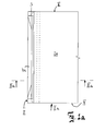
Figur 2- die Ansicht gemäß Sichtpfeil II nach
Figur 1 - Figur 2a
- die Ansicht gemäß Sichtpfeil IIa nach
Figur 1a zweier Paneele an der Verbindungsstelle; Figur 3- den Schnitt entlang der Linie III-III nach
Figur 1 Figur 3a- den Schnitt entlang der Linie IIIa-IIIa nach
Figur 1a ; - Figur 4
- die perspektivische Teilschnittdarstellung des Paneels nach
Figur 1 Figur 4a- die perspektivische Teilschnittdarstellung des Paneels nach
Figur 1a ; Figur 5- die Draufsicht auf eine dritte Ausführungsform eines Paneels in Teildarstellung;
Figur 6- die Ansicht gemäß Sichtpfeil
VI nach Figur 5 zweier Paneele an der Verbindungsstelle; Figur 7- den Schnitt entlang der Linie VII-
VII nach Figur 5 zweier Paneele an der Verbindungsstelle; Figur 8- eine perspektivische Teilschnittdarstellung des Paneels nach
Figur 5 ; Figur 9- die Darstellung zweier miteinander an der Querseite verbundener Paneele einer weiteren Ausführungsform im Teilschnitt;
Figur 10- die Ansicht zweier an den Querseiten miteinander verbundener Paneele in Teilansicht gemäß der Schnittdarstellung in
Figur 9 - Figur 11
- die perspektivische Teilschnittdarstellung des Paneels nach
Figur 9 .
- FIG. 1
- the plan view of a first panel in partial view;
- FIG. 1a
- the plan view of another panel in partial view;
- FIG. 2
- the view according to arrow II after
FIG. 1 two panels at the junction; - FIG. 2a
- the view according to arrow IIa after
FIG. 1a two panels at the junction; - FIG. 3
- the section along the line III-III after
FIG. 1 two panels at the junction; - FIG. 3a
- the section along the line IIIa-IIIa after
FIG. 1a ; - FIG. 4
- the perspective partial sectional view of the panel after
FIG. 1 ; - FIG. 4a
- the perspective partial sectional view of the panel after
FIG. 1a ; - FIG. 5
- the plan view of a third embodiment of a panel in partial view;
- FIG. 6
- the view according to arrow VI after
FIG. 5 two panels at the junction; - FIG. 7
- the section along the line VII-VII according to
FIG. 5 two panels at the junction; - FIG. 8
- a perspective partial sectional view of the panel after
FIG. 5 ; - FIG. 9
- the representation of two connected to each other on the transverse side panels of another embodiment in partial section;
- FIG. 10
- the view of two interconnected on the transverse sides panels in partial view according to the sectional view in
FIG. 9 ; - FIG. 11
- the perspective partial sectional view of the panel after
FIG. 9 ,
Die Paneele 1, 2 bzw. 1a, 2a sind identisch ausgebildet. An ihrer einen Seitenkante I, la sind sie mit einer Feder 6, 6a und an der gegenüberliegenden Seitenkante II, IIa mit einer Nut 3, 3a ausgebildet. Die Nut 3, 3a weist eine Unterlippe 4, 4a und eine nicht näher bezeichnete Oberlippe auf. Der Kern 37 besteht aus Holzwerkstoff oder einem Holzwerkstoff-Kunststoff-Gemisch.The
Die in den
An der Unterlippe 4, 4a ist das in Richtung der Oberseite 16 hervorragende Federelement 5, 5a angeordnet, das über seine beiden Enden 12, 13 mit dem Kern 37 der Paneele 1, 2; 1a, 2a verbunden ist. Gegenüber dem Kern 37 ist das Federelement 5, 5a durch den vertikalen Schlitz 8, 8a getrennt. Mit seiner oberen Kante 18 endet das Federelement mit dem Nutgrund. Da das Federelement 5, 5a nur an seinen beiden Enden 12, 13 mit dem Kern 37 verbunden ist, ist es in vertikaler Richtung V beweglich. Die innere Wandung 8', die sich am Kern 37 infolge des Schlitzes 8, 8a ausbildet, dient als Anschlag in horizontaler Richtung für das Federelement 5, 5a, damit dieses in horizontaler Richtung gegen Überdehnung geschützt ist. Wie
Bei dem in den
An der dem Federelement 30 gegenüberliegenden Seitenkante IV ist das Paneel 21 mit einer sich im Wesentlichen in horizontaler Richtung H erstreckenden Nut 29 versehen, deren obere Seitenwandung eine im Wesentlichen horizontal verlaufende Verriegelungskante 24 ausbildet. Der Nutgrund der Nut 29 verläuft parallel zur äußeren Kante 23c des Federelementes 23, was die Fertigung der Nut 29 erleichtert. Er könnte aber strikt in vertikaler Richtung V oder mit einem vom Winkel der äußeren Kante 23c des Federelementes 23 abweichenden Winkel ausgeführt sein.At the side edge IV opposite the
Die Verriegelung der beiden Paneele 21, 22 in horizontaler Richtung H erfolgt über die durch eine Stufenprofilierung fräsend erzeugten Hakenelemente 40, 41 und in vertikaler Richtung V über das Federelement 23 in Verbindung mit der Verriegelungskante 24 der Nut 29. Am sich nach unten erstreckenden Absatz 25 des Hakenelementes 41 ist eine zumindest teilweise plane Kopffläche 32 ausgebildet, die zusammenwirkt mit einer am Hakenelement 40 an der gegenüberliegenden Seitenkante IV ausgebildeten Anlagefläche 33, die hinter dem Absatz 26 zurückragt. Die Kopffläche 12 und die Auflagefläche 13 enden in derselben horizontalen Ebene E, so dass sich miteinander verbundene Paneele 21, 22 aufeinander abstützen. Die Profilierung der Hakenelemente 40, 41 ist so gewählt, dass in der Verbindungsstelle eine Vorspannung erzeugt wird und die vertikalen Anlageflächen 35, 36 der Paneele 21, 22 aufeinander zugepresst werden, so dass an der Oberseite 16 zweier miteinander verbundener Paneele 21, 22 kein sichtbarer Spalt entsteht. Um das Fügen der Paneele 21, 22 zu erleichtern, sind der nach oben ragende Absatz 26 des Hakenelementes 40 und der nach unten ragende Absatz 25 des Hakenelementes 41 an ihren Kanten gefast bzw. verrundet. Um die Fertigung zur Ausbildung des Federelementes 23 zu vereinfachen, können entweder der horizontal verlaufende Schlitz 31 oder der im Wesentlichen vertikal verlaufende Schlitz 30 durchgängig sein, also über die volle Länge I der Seitenkante III reichen.The locking of the two
Bei allen vorstehend beschriebenen Ausführungsformen bestimmt die Fläche, also die Höhe und die Breite, mit der die Enden 12, 13 des Federelementes 5, 5a bzw. 23a, 23b des Federelementes 23 mit dem Kern 37 verbunden sind, die Federrate des Federelementes. Über die Länge L, I der Seitenkante I, II, III können mehrere Federelemente 23 ausgebildet sein.In all the embodiments described above, determines the surface, so the height and the width at which the ends 12, 13 of the
- 1
- Paneel
- 1a
- Paneel
- 2
- Paneel
- 2a
- Paneel
- 3
- Nut
- 3a
- Nut
- 4
- Unterlippe
- 4a
- Unterlippe
- 4'
- Hinterschnitt/Hinterschneidung
- 5
- Federelement
- 5a
- Federelement
- 5'
- Unterkante
- 6
- Feder
- 6a
- Feder
- 6'
- Hinterschneidung
- 7
- Schlitz
- 8
- Schlitz
- 9
- Schlitz
- 10
- schräge Kante
- 12
- Ende
- 13
- Ende
- 14
- Ende
- 15
- Ende
- 16
- Oberseite
- 17
- Unterseite
- 18
- Oberseite
- 21
- Paneel
- 22
- Paneel
- 23
- Federelement
- 23a
- Ende
- 23b
- Ende
- 23c
- äußere Kante
- 23d
- untere Kante
- 24
- Verriegelungskante
- 25
- Absatz
- 26
- Absatz
- 29
- Nut
- 30
- Schlitz
- 32
- Kopffläche
- 33
- Auflagefläche
- 35
- vertikale Fläche
- 36
- vertikale Fläche
- 37
- Kern
- 40
- Hakenelement
- 41
- Hakenelement
- E
- Ebene
- H
- horizontale Richtung
- L
- Länge
- I
- Länge
- V
- vertikale Richtung
- I
- Seitenkante
- II
- Seitenkante
- III
- Seitenkante
- IV
- Seitenkante
- 1
- paneling
- 1a
- paneling
- 2
- paneling
- 2a
- paneling
- 3
- groove
- 3a
- groove
- 4
- bottom lip
- 4a
- bottom lip
- 4 '
- Undercut / undercut
- 5
- spring element
- 5a
- spring element
- 5 '
- lower edge
- 6
- feather
- 6a
- feather
- 6 '
- undercut
- 7
- slot
- 8th
- slot
- 9
- slot
- 10
- sloping edge
- 12
- The End
- 13
- The End
- 14
- The End
- 15
- The End
- 16
- top
- 17
- bottom
- 18
- top
- 21
- paneling
- 22
- paneling
- 23
- spring element
- 23a
- The End
- 23b
- The End
- 23c
- outer edge
- 23d
- lower edge
- 24
- locking edge
- 25
- paragraph
- 26
- paragraph
- 29
- groove
- 30
- slot
- 32
- head face
- 33
- bearing surface
- 35
- vertical surface
- 36
- vertical surface
- 37
- core
- 40
- hook element
- 41
- hook element
- e
- level
- H
- horizontal direction
- L
- length
- I
- length
- V
- vertical direction
- I
- side edge
- II
- side edge
- III
- side edge
- IV
- side edge
Claims (11)
Priority Applications (1)
| Application Number | Priority Date | Filing Date | Title |
|---|---|---|---|
| PL08007084T PL1980683T3 (en) | 2007-04-10 | 2008-04-10 | Panel, in particular floor panel |
Applications Claiming Priority (1)
| Application Number | Priority Date | Filing Date | Title |
|---|---|---|---|
| DE102007017087A DE102007017087B4 (en) | 2007-04-10 | 2007-04-10 | Panel, in particular floor panel |
Publications (3)
| Publication Number | Publication Date |
|---|---|
| EP1980683A2 true EP1980683A2 (en) | 2008-10-15 |
| EP1980683A3 EP1980683A3 (en) | 2009-01-21 |
| EP1980683B1 EP1980683B1 (en) | 2011-02-23 |
Family
ID=39587855
Family Applications (1)
| Application Number | Title | Priority Date | Filing Date |
|---|---|---|---|
| EP08007084A Active EP1980683B1 (en) | 2007-04-10 | 2008-04-10 | Panel, in particular floor panel |
Country Status (6)
| Country | Link |
|---|---|
| EP (1) | EP1980683B1 (en) |
| AT (1) | ATE499494T1 (en) |
| DE (2) | DE102007017087B4 (en) |
| ES (1) | ES2359276T3 (en) |
| PL (1) | PL1980683T3 (en) |
| PT (1) | PT1980683E (en) |
Cited By (34)
| Publication number | Priority date | Publication date | Assignee | Title |
|---|---|---|---|---|
| US20100218450A1 (en) * | 2009-02-27 | 2010-09-02 | Flooing Technologies Ltd. | Panel, method of joining panels and method manufacturing panels |
| US8191334B2 (en) | 2008-07-03 | 2012-06-05 | Flooring Technologies Ltd. | Method for laying floor panels |
| WO2013151493A1 (en) * | 2012-04-04 | 2013-10-10 | Välinge Innovation AB | Method for producing a mechanical locking system for building panels |
| WO2013151494A1 (en) * | 2012-04-04 | 2013-10-10 | Välinge Innovation AB | Building panel with a mechanical locking system |
| US8572922B2 (en) | 2011-07-05 | 2013-11-05 | Valinge Flooring Technology Ab | Mechanical locking of floor panels with a glued tongue |
| US8596013B2 (en) | 2012-04-04 | 2013-12-03 | Valinge Innovation Ab | Building panel with a mechanical locking system |
| US8627862B2 (en) | 2008-01-31 | 2014-01-14 | Valinge Innovation Ab | Mechanical locking of floor panels, methods to install and uninstall panels, a method and an equipment to produce the locking system, a method to connect a displaceable tongue to a panel and a tongue blank |
| US8650826B2 (en) | 2011-07-19 | 2014-02-18 | Valinge Flooring Technology Ab | Mechanical locking system for floor panels |
| US8763340B2 (en) | 2011-08-15 | 2014-07-01 | Valinge Flooring Technology Ab | Mechanical locking system for floor panels |
| US8769905B2 (en) | 2011-08-15 | 2014-07-08 | Valinge Flooring Technology Ab | Mechanical locking system for floor panels |
| US8776473B2 (en) | 2010-02-04 | 2014-07-15 | Valinge Innovation Ab | Mechanical locking system for floor panels |
| US8857126B2 (en) | 2011-08-15 | 2014-10-14 | Valinge Flooring Technology Ab | Mechanical locking system for floor panels |
| US8887468B2 (en) | 2011-05-06 | 2014-11-18 | Valinge Flooring Technology Ab | Mechanical locking system for building panels |
| US8898988B2 (en) | 2010-01-12 | 2014-12-02 | Valinge Innovation Ab | Mechanical locking system for floor panels |
| US8925274B2 (en) | 2008-05-15 | 2015-01-06 | Valinge Innovation Ab | Mechanical locking of building panels |
| US9003735B2 (en) | 2010-04-15 | 2015-04-14 | Spanolux N.V.—Div. Balterio | Floor panel assembly |
| US9212492B2 (en) | 2007-11-07 | 2015-12-15 | Valinge Innovation Ab | Mechanical locking of floor panels with vertical snap folding |
| US9216541B2 (en) | 2012-04-04 | 2015-12-22 | Valinge Innovation Ab | Method for producing a mechanical locking system for building panels |
| US9260870B2 (en) | 2014-03-24 | 2016-02-16 | Ivc N.V. | Set of mutually lockable panels |
| US9366036B2 (en) | 2012-11-22 | 2016-06-14 | Ceraloc Innovation Ab | Mechanical locking system for floor panels |
| WO2016114712A1 (en) * | 2015-01-16 | 2016-07-21 | Ceraloc Innovation Ab | Mechanical locking system for floor panels |
| US9458634B2 (en) | 2014-05-14 | 2016-10-04 | Valinge Innovation Ab | Building panel with a mechanical locking system |
| CN106013722A (en) * | 2016-06-25 | 2016-10-12 | 宜兴市华龙塑木新材料有限公司 | Wood-plastic side board provided with tenon |
| US9725912B2 (en) | 2011-07-11 | 2017-08-08 | Ceraloc Innovation Ab | Mechanical locking system for floor panels |
| US9803374B2 (en) | 2014-12-22 | 2017-10-31 | Ceraloc Innovation Ab | Mechanical locking system for floor panels |
| US10017948B2 (en) | 2013-06-27 | 2018-07-10 | Valinge Innovation Ab | Building panel with a mechanical locking system |
| US10138636B2 (en) | 2014-11-27 | 2018-11-27 | Valinge Innovation Ab | Mechanical locking system for floor panels |
| US10246883B2 (en) | 2014-05-14 | 2019-04-02 | Valinge Innovation Ab | Building panel with a mechanical locking system |
| US10280627B2 (en) | 2014-03-24 | 2019-05-07 | Flooring Industries Limited, Sarl | Set of mutually lockable panels |
| US10724251B2 (en) | 2011-03-18 | 2020-07-28 | Valinge Innovation Ab | Vertical joint system and associated surface covering system |
| US11060302B2 (en) | 2019-01-10 | 2021-07-13 | Valinge Innovation Ab | Unlocking system for panels |
| US11987990B2 (en) | 2007-11-07 | 2024-05-21 | Välinge Innovation AB | Mechanical locking of floor panels with vertical snap folding |
| US12509884B2 (en) | 2006-07-11 | 2025-12-30 | Välinge Innovation AB | Mechanical locking of floor panels with a flexible bristle tongue |
| US12559949B2 (en) | 2012-08-27 | 2026-02-24 | Unilin Nordic Ab | Panel |
Families Citing this family (1)
| Publication number | Priority date | Publication date | Assignee | Title |
|---|---|---|---|---|
| CA2786768C (en) | 2010-01-14 | 2018-09-04 | Unilin, Bvba | Floor panel assembly and floor panel for use therein |
Citations (5)
| Publication number | Priority date | Publication date | Assignee | Title |
|---|---|---|---|---|
| WO1997047834A1 (en) | 1996-06-11 | 1997-12-18 | Unilin Beheer B.V. | Floor covering, consisting of hard floor panels and method for manufacturing such floor panels |
| DE10156775A1 (en) | 2001-11-19 | 2003-06-05 | Lindner Ag | Pavement slab connections are recessed to one side of main locking groove for locking nose of adjoining slab and grooved below for security stop to prevent tongue piece deflection when engaged. |
| DE10336614A1 (en) | 2003-08-06 | 2005-03-03 | Hamberger Industriewerke Gmbh | Connection for plate-shaped components, especially floor panels, comprises a tongue having a slit arranged at an angle to the horizontal that forms a tongue protrusion which snaps into a locking recess of a groove cheek |
| EP1516977A1 (en) | 2003-09-17 | 2005-03-23 | Cosmo S.p.A. | Panel, in particular for wood floors |
| DE202004015275U1 (en) | 2004-09-17 | 2005-05-04 | Hdm Gmbh | Panel, in particular, floor panel comprises a tongue section which carries or interacts with a locking element and has a greater elasticity than the locking element |
Family Cites Families (10)
| Publication number | Priority date | Publication date | Assignee | Title |
|---|---|---|---|---|
| DE7402354U (en) * | 1974-05-30 | Vaw Leichtmetall Gmbh | Securing device for panels | |
| DE19962830C2 (en) * | 1999-12-23 | 2002-07-18 | Hamberger Industriewerke Gmbh | connection |
| DE20022062U1 (en) * | 2000-02-22 | 2001-04-12 | Kronotec Ag, Luzern | Panel, especially floor panel |
| DE20112474U1 (en) * | 2001-07-28 | 2002-12-19 | M. Kaindl, Wals | Panel, for example for floor, wall and / or ceiling cladding |
| DE10206877B4 (en) * | 2002-02-18 | 2004-02-05 | E.F.P. Floor Products Fussböden GmbH | Panel, especially floor panel |
| ES2327502T5 (en) * | 2002-04-05 | 2013-03-14 | Tilo Gmbh | Floor boards |
| DE20304761U1 (en) * | 2003-03-24 | 2004-04-08 | Kronotec Ag | Device for connecting building boards, in particular floor panels |
| DE102004001363A1 (en) * | 2004-01-07 | 2005-08-04 | Hamberger Industriewerke Gmbh | Floor units interconnection, has panel with interlocking projection having spring blade, which lies in interlocked position with abutting face of active surface of vertical interlocking projection |
| FR2884267B1 (en) * | 2005-04-06 | 2007-07-06 | Jean Pierre Grau | MODULAR FLOORING OF SLABS WITH RAPID ASSEMBLY OF FRAMING MODULES |
| DE102005061099A1 (en) * | 2005-07-25 | 2007-03-29 | Hipper, August, Dipl.-Ing. (FH) | Glueless connection for floor panel, has slit and stud that are arranged along two connected edges, where slab planes are fixed in vertical direction through horizontal attachment surfaces of stud in slit and of notch |
-
2007
- 2007-04-10 DE DE102007017087A patent/DE102007017087B4/en active Active
-
2008
- 2008-04-10 ES ES08007084T patent/ES2359276T3/en active Active
- 2008-04-10 AT AT08007084T patent/ATE499494T1/en active
- 2008-04-10 PL PL08007084T patent/PL1980683T3/en unknown
- 2008-04-10 PT PT08007084T patent/PT1980683E/en unknown
- 2008-04-10 EP EP08007084A patent/EP1980683B1/en active Active
- 2008-04-10 DE DE502008002648T patent/DE502008002648D1/en active Active
Patent Citations (5)
| Publication number | Priority date | Publication date | Assignee | Title |
|---|---|---|---|---|
| WO1997047834A1 (en) | 1996-06-11 | 1997-12-18 | Unilin Beheer B.V. | Floor covering, consisting of hard floor panels and method for manufacturing such floor panels |
| DE10156775A1 (en) | 2001-11-19 | 2003-06-05 | Lindner Ag | Pavement slab connections are recessed to one side of main locking groove for locking nose of adjoining slab and grooved below for security stop to prevent tongue piece deflection when engaged. |
| DE10336614A1 (en) | 2003-08-06 | 2005-03-03 | Hamberger Industriewerke Gmbh | Connection for plate-shaped components, especially floor panels, comprises a tongue having a slit arranged at an angle to the horizontal that forms a tongue protrusion which snaps into a locking recess of a groove cheek |
| EP1516977A1 (en) | 2003-09-17 | 2005-03-23 | Cosmo S.p.A. | Panel, in particular for wood floors |
| DE202004015275U1 (en) | 2004-09-17 | 2005-05-04 | Hdm Gmbh | Panel, in particular, floor panel comprises a tongue section which carries or interacts with a locking element and has a greater elasticity than the locking element |
Cited By (85)
| Publication number | Priority date | Publication date | Assignee | Title |
|---|---|---|---|---|
| US12509884B2 (en) | 2006-07-11 | 2025-12-30 | Välinge Innovation AB | Mechanical locking of floor panels with a flexible bristle tongue |
| US9777487B2 (en) | 2007-11-07 | 2017-10-03 | Valinge Innovation Ab | Mechanical locking of floor panels with vertical snap folding |
| US10214917B2 (en) | 2007-11-07 | 2019-02-26 | Valinge Innovation Ab | Mechanical locking of floor panels with vertical snap folding |
| US9212492B2 (en) | 2007-11-07 | 2015-12-15 | Valinge Innovation Ab | Mechanical locking of floor panels with vertical snap folding |
| US11987990B2 (en) | 2007-11-07 | 2024-05-21 | Välinge Innovation AB | Mechanical locking of floor panels with vertical snap folding |
| US11519183B2 (en) | 2007-11-07 | 2022-12-06 | Valinge Innovation Ab | Mechanical locking of floor panels with vertical snap folding |
| US8627862B2 (en) | 2008-01-31 | 2014-01-14 | Valinge Innovation Ab | Mechanical locking of floor panels, methods to install and uninstall panels, a method and an equipment to produce the locking system, a method to connect a displaceable tongue to a panel and a tongue blank |
| US9340974B2 (en) | 2008-01-31 | 2016-05-17 | Valinge Innovation Ab | Mechanical locking of floor panels |
| US8925274B2 (en) | 2008-05-15 | 2015-01-06 | Valinge Innovation Ab | Mechanical locking of building panels |
| US8191334B2 (en) | 2008-07-03 | 2012-06-05 | Flooring Technologies Ltd. | Method for laying floor panels |
| US8375674B2 (en) * | 2009-02-27 | 2013-02-19 | Flooring Technologies Ltd. | Panel, method of joining panels and method manufacturing panels |
| US20100218450A1 (en) * | 2009-02-27 | 2010-09-02 | Flooing Technologies Ltd. | Panel, method of joining panels and method manufacturing panels |
| US8898988B2 (en) | 2010-01-12 | 2014-12-02 | Valinge Innovation Ab | Mechanical locking system for floor panels |
| US9453347B2 (en) | 2010-01-12 | 2016-09-27 | Valinge Innovation Ab | Mechanical locking system for floor panels |
| US9428919B2 (en) | 2010-02-04 | 2016-08-30 | Valinge Innovation Ab | Mechanical locking system for floor panels |
| US8776473B2 (en) | 2010-02-04 | 2014-07-15 | Valinge Innovation Ab | Mechanical locking system for floor panels |
| US9003735B2 (en) | 2010-04-15 | 2015-04-14 | Spanolux N.V.—Div. Balterio | Floor panel assembly |
| US11613897B2 (en) | 2011-03-18 | 2023-03-28 | Valinge Innovation Ab | Vertical joint system and associated surface covering system |
| US11091920B2 (en) | 2011-03-18 | 2021-08-17 | Valinge Innovation Ab | Vertical joint system and associated surface covering system |
| US12139918B2 (en) | 2011-03-18 | 2024-11-12 | Välinge Innovation AB | Vertical joint system and associated surface covering system |
| US10724251B2 (en) | 2011-03-18 | 2020-07-28 | Valinge Innovation Ab | Vertical joint system and associated surface covering system |
| US8887468B2 (en) | 2011-05-06 | 2014-11-18 | Valinge Flooring Technology Ab | Mechanical locking system for building panels |
| US11781577B2 (en) | 2011-05-06 | 2023-10-10 | Valinge Innovation Ab | Mechanical locking system for building panels |
| US12276293B2 (en) | 2011-05-06 | 2025-04-15 | Välinge Innovation AB | Mechanical locking system for building panels |
| US8959866B2 (en) | 2011-07-05 | 2015-02-24 | Valinge Flooring Technology Ab | Mechanical locking of floor panels with a glued tongue |
| US8572922B2 (en) | 2011-07-05 | 2013-11-05 | Valinge Flooring Technology Ab | Mechanical locking of floor panels with a glued tongue |
| US9856656B2 (en) | 2011-07-05 | 2018-01-02 | Ceraloc Innovation Ab | Mechanical locking of floor panels with a glued tongue |
| US10519676B2 (en) | 2011-07-11 | 2019-12-31 | Ceraloc Innovation Ab | Mechanical locking system for floor panels |
| US9725912B2 (en) | 2011-07-11 | 2017-08-08 | Ceraloc Innovation Ab | Mechanical locking system for floor panels |
| US10995501B2 (en) | 2011-07-11 | 2021-05-04 | Ceraloc Innovation Ab | Mechanical locking system for floor panels |
| US10240349B2 (en) | 2011-07-19 | 2019-03-26 | Ceraloc Innovation Ab | Mechanical locking system for floor panels |
| US9874027B2 (en) | 2011-07-19 | 2018-01-23 | Ceraloc Innovation Ab | Mechanical locking system for floor panels |
| US9284737B2 (en) | 2011-07-19 | 2016-03-15 | Valinge Flooring Technology Ab | Mechanical locking system for floor panels |
| US8650826B2 (en) | 2011-07-19 | 2014-02-18 | Valinge Flooring Technology Ab | Mechanical locking system for floor panels |
| US9051738B2 (en) | 2011-08-15 | 2015-06-09 | Valinge Flooring Technology Ab | Mechanical locking system for floor panels |
| US9388584B2 (en) | 2011-08-15 | 2016-07-12 | Ceraloc Innovation Ab | Mechanical locking system for floor panels |
| US8857126B2 (en) | 2011-08-15 | 2014-10-14 | Valinge Flooring Technology Ab | Mechanical locking system for floor panels |
| US10968639B2 (en) | 2011-08-15 | 2021-04-06 | Ceraloc Innovation Ab | Mechanical locking system for floor panels |
| US8769905B2 (en) | 2011-08-15 | 2014-07-08 | Valinge Flooring Technology Ab | Mechanical locking system for floor panels |
| US8763340B2 (en) | 2011-08-15 | 2014-07-01 | Valinge Flooring Technology Ab | Mechanical locking system for floor panels |
| US10180005B2 (en) | 2011-08-15 | 2019-01-15 | Ceraloc Innovation Ab | Mechanical locking system for floor panels |
| US9316002B2 (en) | 2012-04-04 | 2016-04-19 | Valinge Innovation Ab | Building panel with a mechanical locking system |
| US8973331B2 (en) | 2012-04-04 | 2015-03-10 | Valinge Innovation Ab | Building panel with a mechanical locking system |
| WO2013151493A1 (en) * | 2012-04-04 | 2013-10-10 | Välinge Innovation AB | Method for producing a mechanical locking system for building panels |
| US9951526B2 (en) | 2012-04-04 | 2018-04-24 | Valinge Innovation Ab | Mechanical locking system for building panels |
| RU2622945C2 (en) * | 2012-04-04 | 2017-06-21 | Велинге Инновейшн Аб | Structural panel with mechanical locking system |
| US10125488B2 (en) | 2012-04-04 | 2018-11-13 | Valinge Innovation Ab | Building panel with a mechanical locking system |
| US9663940B2 (en) | 2012-04-04 | 2017-05-30 | Valinge Innovation Ab | Building panel with a mechanical locking system |
| WO2013151494A1 (en) * | 2012-04-04 | 2013-10-10 | Välinge Innovation AB | Building panel with a mechanical locking system |
| RU2621244C2 (en) * | 2012-04-04 | 2017-06-01 | Велинге Инновейшн Аб | Method for producing mechanical locking system for construction panels |
| US10794065B2 (en) | 2012-04-04 | 2020-10-06 | Valinge Innovation Ab | Method for producing a mechanical locking system for building panels |
| KR20140144711A (en) * | 2012-04-04 | 2014-12-19 | 뵈린게 이노베이션 에이비이 | Method for producing a mechanical locking system for building panels |
| US9091077B2 (en) | 2012-04-04 | 2015-07-28 | Valinge Innovation Ab | Building panel with a mechanical locking system |
| KR102149416B1 (en) | 2012-04-04 | 2020-08-28 | 뵈린게 이노베이션 에이비이 | Method for producing a mechanical locking system for building panels |
| US9216541B2 (en) | 2012-04-04 | 2015-12-22 | Valinge Innovation Ab | Method for producing a mechanical locking system for building panels |
| US10480196B2 (en) | 2012-04-04 | 2019-11-19 | Valinge Innovation Ab | Building panel with a mechanical locking system |
| US8596013B2 (en) | 2012-04-04 | 2013-12-03 | Valinge Innovation Ab | Building panel with a mechanical locking system |
| US12559949B2 (en) | 2012-08-27 | 2026-02-24 | Unilin Nordic Ab | Panel |
| US9771723B2 (en) | 2012-11-22 | 2017-09-26 | Ceraloc Innovation Ab | Mechanical locking system for floor panels |
| US9366036B2 (en) | 2012-11-22 | 2016-06-14 | Ceraloc Innovation Ab | Mechanical locking system for floor panels |
| US12312816B2 (en) | 2013-06-27 | 2025-05-27 | Välinge Innovation AB | Building panel with a mechanical locking system |
| US11746536B2 (en) | 2013-06-27 | 2023-09-05 | Valinge Innovation Ab | Building panel with a mechanical locking system |
| US10352049B2 (en) | 2013-06-27 | 2019-07-16 | Valinge Innovation Ab | Building panel with a mechanical locking system |
| US11066835B2 (en) | 2013-06-27 | 2021-07-20 | Valinge Innovation Ab | Building panel with a mechanical locking system |
| US10017948B2 (en) | 2013-06-27 | 2018-07-10 | Valinge Innovation Ab | Building panel with a mechanical locking system |
| US9260870B2 (en) | 2014-03-24 | 2016-02-16 | Ivc N.V. | Set of mutually lockable panels |
| US10612250B2 (en) | 2014-03-24 | 2020-04-07 | Flooring Industries Limited, Sarl | Set of mutually lockable panels |
| US10280627B2 (en) | 2014-03-24 | 2019-05-07 | Flooring Industries Limited, Sarl | Set of mutually lockable panels |
| US10246883B2 (en) | 2014-05-14 | 2019-04-02 | Valinge Innovation Ab | Building panel with a mechanical locking system |
| US9458634B2 (en) | 2014-05-14 | 2016-10-04 | Valinge Innovation Ab | Building panel with a mechanical locking system |
| US10138636B2 (en) | 2014-11-27 | 2018-11-27 | Valinge Innovation Ab | Mechanical locking system for floor panels |
| US10731358B2 (en) | 2014-11-27 | 2020-08-04 | Valinge Innovation Ab | Mechanical locking system for floor panels |
| US11261608B2 (en) | 2014-11-27 | 2022-03-01 | Valinge Innovation Ab | Mechanical locking system for floor panels |
| US10161139B2 (en) | 2014-12-22 | 2018-12-25 | Ceraloc Innovation Ab | Mechanical locking system for floor panels |
| US11174646B2 (en) | 2014-12-22 | 2021-11-16 | Ceraloc Innovation Ab | Mechanical locking system for floor panels |
| US11913236B2 (en) | 2014-12-22 | 2024-02-27 | Ceraloc Innovation Ab | Mechanical locking system for floor panels |
| US10570625B2 (en) | 2014-12-22 | 2020-02-25 | Ceraloc Innovation Ab | Mechanical locking system for floor panels |
| US9803374B2 (en) | 2014-12-22 | 2017-10-31 | Ceraloc Innovation Ab | Mechanical locking system for floor panels |
| US10538922B2 (en) | 2015-01-16 | 2020-01-21 | Ceraloc Innovation Ab | Mechanical locking system for floor panels |
| US11274453B2 (en) | 2015-01-16 | 2022-03-15 | Ceraloc Innovation Ab | Mechanical locking system for floor panels |
| WO2016114712A1 (en) * | 2015-01-16 | 2016-07-21 | Ceraloc Innovation Ab | Mechanical locking system for floor panels |
| CN106013722A (en) * | 2016-06-25 | 2016-10-12 | 宜兴市华龙塑木新材料有限公司 | Wood-plastic side board provided with tenon |
| US11060302B2 (en) | 2019-01-10 | 2021-07-13 | Valinge Innovation Ab | Unlocking system for panels |
| US11781324B2 (en) | 2019-01-10 | 2023-10-10 | Välinge Innovation AB | Unlocking system for panels |
| US12338637B2 (en) | 2019-01-10 | 2025-06-24 | Välinge Innovation AB | Unlocking system for panels |
Also Published As
| Publication number | Publication date |
|---|---|
| ATE499494T1 (en) | 2011-03-15 |
| DE502008002648D1 (en) | 2011-04-07 |
| PL1980683T3 (en) | 2011-07-29 |
| DE102007017087A1 (en) | 2008-10-23 |
| EP1980683A3 (en) | 2009-01-21 |
| ES2359276T3 (en) | 2011-05-20 |
| PT1980683E (en) | 2011-05-16 |
| DE102007017087B4 (en) | 2009-06-25 |
| EP1980683B1 (en) | 2011-02-23 |
Similar Documents
| Publication | Publication Date | Title |
|---|---|---|
| EP1980683B1 (en) | Panel, in particular floor panel | |
| EP1994241B1 (en) | Panel, particularly floor panel | |
| EP2057327B1 (en) | Panel, especially floor panel | |
| DE10101202B4 (en) | parquet board | |
| EP1294995B1 (en) | Flooring system comprising a plurality of identical floorboards | |
| EP2226447B1 (en) | Panelling, in particular floor panelling | |
| DE102009048050B3 (en) | Surface made of mechanical interconnectable elements | |
| EP2208835B1 (en) | Panelling, in particular floor panelling | |
| EP1261785B1 (en) | Panel, in particular flooring panel | |
| EP1350904B2 (en) | Floor planks | |
| DE69916666T2 (en) | Rectangular base plate | |
| DE10243196B4 (en) | Panels with connection bracket | |
| EP2213812A1 (en) | Panelling, in particular floor panelling | |
| EP1527240A1 (en) | Arrangement of parts comprising connecting elements | |
| EP2250330A2 (en) | Method for laying floor panels | |
| DE60131544T2 (en) | Arrangement of a support system and method for producing a fastening | |
| DE10305695B4 (en) | Cladding panel, in particular floor panel | |
| DE19929896B4 (en) | Fixing system for panels | |
| DE102007046598B4 (en) | paneling | |
| DE20119830U1 (en) | Arrangement of components | |
| EP3553250A1 (en) | System for the formation of a floor | |
| DE20211183U1 (en) | New design of tongue and groove area for joining two flat wooden sheets or boards | |
| DE20205963U1 (en) | Flooring | |
| DE20122682U1 (en) | Rectangular floorboard assembly for joint system, has locking surfaces, which are located at upper portion of respective locking element close to top of locking element and at distance from upper side of respective strip | |
| WO2014032656A1 (en) | Panel element |
Legal Events
| Date | Code | Title | Description |
|---|---|---|---|
| PUAI | Public reference made under article 153(3) epc to a published international application that has entered the european phase |
Free format text: ORIGINAL CODE: 0009012 |
|
| AK | Designated contracting states |
Kind code of ref document: A2 Designated state(s): AT BE BG CH CY CZ DE DK EE ES FI FR GB GR HR HU IE IS IT LI LT LU LV MC MT NL NO PL PT RO SE SI SK TR |
|
| AX | Request for extension of the european patent |
Extension state: AL BA MK RS |
|
| PUAL | Search report despatched |
Free format text: ORIGINAL CODE: 0009013 |
|
| AK | Designated contracting states |
Kind code of ref document: A3 Designated state(s): AT BE BG CH CY CZ DE DK EE ES FI FR GB GR HR HU IE IS IT LI LT LU LV MC MT NL NO PL PT RO SE SI SK TR |
|
| AX | Request for extension of the european patent |
Extension state: AL BA MK RS |
|
| 17P | Request for examination filed |
Effective date: 20090314 |
|
| AKX | Designation fees paid |
Designated state(s): AT BE BG CH CY CZ DE DK EE ES FI FR GB GR HR HU IE IS IT LI LT LU LV MC MT NL NO PL PT RO SE SI SK TR |
|
| GRAP | Despatch of communication of intention to grant a patent |
Free format text: ORIGINAL CODE: EPIDOSNIGR1 |
|
| GRAS | Grant fee paid |
Free format text: ORIGINAL CODE: EPIDOSNIGR3 |
|
| GRAA | (expected) grant |
Free format text: ORIGINAL CODE: 0009210 |
|
| AK | Designated contracting states |
Kind code of ref document: B1 Designated state(s): AT BE BG CH CY CZ DE DK EE ES FI FR GB GR HR HU IE IS IT LI LT LU LV MC MT NL NO PL PT RO SE SI SK TR |
|
| REG | Reference to a national code |
Ref country code: GB Ref legal event code: FG4D Free format text: NOT ENGLISH |
|
| REG | Reference to a national code |
Ref country code: CH Ref legal event code: EP |
|
| REG | Reference to a national code |
Ref country code: IE Ref legal event code: FG4D Free format text: LANGUAGE OF EP DOCUMENT: GERMAN |
|
| REG | Reference to a national code |
Ref country code: CH Ref legal event code: NV Representative=s name: BRAUNPAT BRAUN EDER AG |
|
| REF | Corresponds to: |
Ref document number: 502008002648 Country of ref document: DE Date of ref document: 20110407 Kind code of ref document: P |
|
| REG | Reference to a national code |
Ref country code: DE Ref legal event code: R096 Ref document number: 502008002648 Country of ref document: DE Effective date: 20110407 |
|
| REG | Reference to a national code |
Ref country code: SE Ref legal event code: TRGR |
|
| REG | Reference to a national code |
Ref country code: PT Ref legal event code: SC4A Free format text: AVAILABILITY OF NATIONAL TRANSLATION Effective date: 20110510 |
|
| REG | Reference to a national code |
Ref country code: ES Ref legal event code: FG2A Ref document number: 2359276 Country of ref document: ES Kind code of ref document: T3 Effective date: 20110520 |
|
| REG | Reference to a national code |
Ref country code: NL Ref legal event code: T3 |
|
| LTIE | Lt: invalidation of european patent or patent extension |
Effective date: 20110223 |
|
| PG25 | Lapsed in a contracting state [announced via postgrant information from national office to epo] |
Ref country code: LT Free format text: LAPSE BECAUSE OF FAILURE TO SUBMIT A TRANSLATION OF THE DESCRIPTION OR TO PAY THE FEE WITHIN THE PRESCRIBED TIME-LIMIT Effective date: 20110223 Ref country code: NO Free format text: LAPSE BECAUSE OF FAILURE TO SUBMIT A TRANSLATION OF THE DESCRIPTION OR TO PAY THE FEE WITHIN THE PRESCRIBED TIME-LIMIT Effective date: 20110523 Ref country code: LV Free format text: LAPSE BECAUSE OF FAILURE TO SUBMIT A TRANSLATION OF THE DESCRIPTION OR TO PAY THE FEE WITHIN THE PRESCRIBED TIME-LIMIT Effective date: 20110223 Ref country code: HR Free format text: LAPSE BECAUSE OF FAILURE TO SUBMIT A TRANSLATION OF THE DESCRIPTION OR TO PAY THE FEE WITHIN THE PRESCRIBED TIME-LIMIT Effective date: 20110223 |
|
| REG | Reference to a national code |
Ref country code: PL Ref legal event code: T3 |
|
| PG25 | Lapsed in a contracting state [announced via postgrant information from national office to epo] |
Ref country code: BG Free format text: LAPSE BECAUSE OF FAILURE TO SUBMIT A TRANSLATION OF THE DESCRIPTION OR TO PAY THE FEE WITHIN THE PRESCRIBED TIME-LIMIT Effective date: 20110523 Ref country code: CY Free format text: LAPSE BECAUSE OF FAILURE TO SUBMIT A TRANSLATION OF THE DESCRIPTION OR TO PAY THE FEE WITHIN THE PRESCRIBED TIME-LIMIT Effective date: 20110223 Ref country code: SI Free format text: LAPSE BECAUSE OF FAILURE TO SUBMIT A TRANSLATION OF THE DESCRIPTION OR TO PAY THE FEE WITHIN THE PRESCRIBED TIME-LIMIT Effective date: 20110223 Ref country code: FI Free format text: LAPSE BECAUSE OF FAILURE TO SUBMIT A TRANSLATION OF THE DESCRIPTION OR TO PAY THE FEE WITHIN THE PRESCRIBED TIME-LIMIT Effective date: 20110223 |
|
| REG | Reference to a national code |
Ref country code: IE Ref legal event code: FD4D |
|
| PG25 | Lapsed in a contracting state [announced via postgrant information from national office to epo] |
Ref country code: IE Free format text: LAPSE BECAUSE OF FAILURE TO SUBMIT A TRANSLATION OF THE DESCRIPTION OR TO PAY THE FEE WITHIN THE PRESCRIBED TIME-LIMIT Effective date: 20110223 Ref country code: DK Free format text: LAPSE BECAUSE OF FAILURE TO SUBMIT A TRANSLATION OF THE DESCRIPTION OR TO PAY THE FEE WITHIN THE PRESCRIBED TIME-LIMIT Effective date: 20110223 Ref country code: EE Free format text: LAPSE BECAUSE OF FAILURE TO SUBMIT A TRANSLATION OF THE DESCRIPTION OR TO PAY THE FEE WITHIN THE PRESCRIBED TIME-LIMIT Effective date: 20110223 |
|
| PG25 | Lapsed in a contracting state [announced via postgrant information from national office to epo] |
Ref country code: CZ Free format text: LAPSE BECAUSE OF FAILURE TO SUBMIT A TRANSLATION OF THE DESCRIPTION OR TO PAY THE FEE WITHIN THE PRESCRIBED TIME-LIMIT Effective date: 20110223 Ref country code: MC Free format text: LAPSE BECAUSE OF NON-PAYMENT OF DUE FEES Effective date: 20110430 Ref country code: RO Free format text: LAPSE BECAUSE OF FAILURE TO SUBMIT A TRANSLATION OF THE DESCRIPTION OR TO PAY THE FEE WITHIN THE PRESCRIBED TIME-LIMIT Effective date: 20110223 Ref country code: SK Free format text: LAPSE BECAUSE OF FAILURE TO SUBMIT A TRANSLATION OF THE DESCRIPTION OR TO PAY THE FEE WITHIN THE PRESCRIBED TIME-LIMIT Effective date: 20110223 |
|
| PG25 | Lapsed in a contracting state [announced via postgrant information from national office to epo] |
Ref country code: MT Free format text: LAPSE BECAUSE OF FAILURE TO SUBMIT A TRANSLATION OF THE DESCRIPTION OR TO PAY THE FEE WITHIN THE PRESCRIBED TIME-LIMIT Effective date: 20110223 |
|
| PLBE | No opposition filed within time limit |
Free format text: ORIGINAL CODE: 0009261 |
|
| STAA | Information on the status of an ep patent application or granted ep patent |
Free format text: STATUS: NO OPPOSITION FILED WITHIN TIME LIMIT |
|
| 26N | No opposition filed |
Effective date: 20111124 |
|
| REG | Reference to a national code |
Ref country code: DE Ref legal event code: R097 Ref document number: 502008002648 Country of ref document: DE Effective date: 20111124 |
|
| PG25 | Lapsed in a contracting state [announced via postgrant information from national office to epo] |
Ref country code: LU Free format text: LAPSE BECAUSE OF NON-PAYMENT OF DUE FEES Effective date: 20110410 |
|
| PG25 | Lapsed in a contracting state [announced via postgrant information from national office to epo] |
Ref country code: IS Free format text: LAPSE BECAUSE OF FAILURE TO SUBMIT A TRANSLATION OF THE DESCRIPTION OR TO PAY THE FEE WITHIN THE PRESCRIBED TIME-LIMIT Effective date: 20110223 |
|
| PG25 | Lapsed in a contracting state [announced via postgrant information from national office to epo] |
Ref country code: HU Free format text: LAPSE BECAUSE OF FAILURE TO SUBMIT A TRANSLATION OF THE DESCRIPTION OR TO PAY THE FEE WITHIN THE PRESCRIBED TIME-LIMIT Effective date: 20110223 |
|
| PG25 | Lapsed in a contracting state [announced via postgrant information from national office to epo] |
Ref country code: GR Free format text: LAPSE BECAUSE OF FAILURE TO SUBMIT A TRANSLATION OF THE DESCRIPTION OR TO PAY THE FEE WITHIN THE PRESCRIBED TIME-LIMIT Effective date: 20110223 |
|
| REG | Reference to a national code |
Ref country code: DE Ref legal event code: R082 Ref document number: 502008002648 Country of ref document: DE Representative=s name: GRAMM, LINS & PARTNER PATENT- UND RECHTSANWAEL, DE |
|
| REG | Reference to a national code |
Ref country code: FR Ref legal event code: PLFP Year of fee payment: 9 |
|
| REG | Reference to a national code |
Ref country code: DE Ref legal event code: R082 Ref document number: 502008002648 Country of ref document: DE Ref country code: DE Ref legal event code: R082 Ref document number: 502008002648 Country of ref document: DE Representative=s name: GRAMM, LINS & PARTNER PATENT- UND RECHTSANWAEL, DE Ref country code: DE Ref legal event code: R081 Ref document number: 502008002648 Country of ref document: DE Owner name: SWISS KRONO TEC AG, CH Free format text: FORMER OWNER: KRONOTEC AG, LUZERN, CH Ref country code: DE Ref legal event code: R081 Ref document number: 502008002648 Country of ref document: DE Owner name: VAELINGE INNOVATION AB, SE Free format text: FORMER OWNER: KRONOTEC AG, LUZERN, CH |
|
| REG | Reference to a national code |
Ref country code: CH Ref legal event code: PFA Owner name: SWISS KRONO TEC AG, CH Free format text: FORMER OWNER: KRONOTEC AG, CH |
|
| REG | Reference to a national code |
Ref country code: FR Ref legal event code: PLFP Year of fee payment: 10 |
|
| REG | Reference to a national code |
Ref country code: NL Ref legal event code: HC Owner name: SWISS KRONO TEC AG; CH Free format text: DETAILS ASSIGNMENT: CHANGE OF OWNER(S), CHANGE OF OWNER(S) NAME; FORMER OWNER NAME: KRONOTEC AG Effective date: 20170421 |
|
| REG | Reference to a national code |
Ref country code: AT Ref legal event code: HC Ref document number: 499494 Country of ref document: AT Kind code of ref document: T Owner name: SWISS KRONO TEC AG, CH Effective date: 20170630 |
|
| REG | Reference to a national code |
Ref country code: FR Ref legal event code: CA Effective date: 20170801 Ref country code: FR Ref legal event code: CD Owner name: KRONOTEC AG, CH Effective date: 20170801 |
|
| REG | Reference to a national code |
Ref country code: FR Ref legal event code: PLFP Year of fee payment: 11 |
|
| REG | Reference to a national code |
Ref country code: CH Ref legal event code: PCAR Free format text: NEW ADDRESS: HOLEESTRASSE 87, 4054 BASEL (CH) |
|
| REG | Reference to a national code |
Ref country code: DE Ref legal event code: R082 Ref document number: 502008002648 Country of ref document: DE Ref country code: DE Ref legal event code: R081 Ref document number: 502008002648 Country of ref document: DE Owner name: VAELINGE INNOVATION AB, SE Free format text: FORMER OWNER: SWISS KRONO TEC AG, LUZERN, CH |
|
| REG | Reference to a national code |
Ref country code: ES Ref legal event code: PC2A Owner name: VALINGE INNOVATION AB Effective date: 20181122 |
|
| REG | Reference to a national code |
Ref country code: CH Ref legal event code: PUE Owner name: VAELINGE INNOVATION AB, SE Free format text: FORMER OWNER: SWISS KRONO TEC AG, CH |
|
| REG | Reference to a national code |
Ref country code: BE Ref legal event code: HC Owner name: SWISS KRONO TEC AG; CH Free format text: DETAILS ASSIGNMENT: CHANGE OF OWNER(S), CHANGEMENT NOM PROPRIETAIRE, NOM ET ADRESSE; FORMER OWNER NAME: KRONOTEC AG Effective date: 20170224 Ref country code: BE Ref legal event code: PD Owner name: VAELINGE INNOVATION AB; SE Free format text: DETAILS ASSIGNMENT: CHANGE OF OWNER(S), CESSION; FORMER OWNER NAME: SWISS KRONO TEC AG Effective date: 20181127 |
|
| REG | Reference to a national code |
Ref country code: GB Ref legal event code: 732E Free format text: REGISTERED BETWEEN 20181203 AND 20181205 |
|
| REG | Reference to a national code |
Ref country code: NL Ref legal event code: PD Owner name: VAELINGE INNOVATION AB; SE Free format text: DETAILS ASSIGNMENT: CHANGE OF OWNER(S), ASSIGNMENT; FORMER OWNER NAME: SWISS KRONO TEC AG Effective date: 20181120 |
|
| REG | Reference to a national code |
Ref country code: AT Ref legal event code: PC Ref document number: 499494 Country of ref document: AT Kind code of ref document: T Owner name: VAELINGE INNOVATION AB, SE Effective date: 20181219 |
|
| P01 | Opt-out of the competence of the unified patent court (upc) registered |
Effective date: 20230522 |
|
| PGFP | Annual fee paid to national office [announced via postgrant information from national office to epo] |
Ref country code: SE Payment date: 20250319 Year of fee payment: 18 |
|
| PGFP | Annual fee paid to national office [announced via postgrant information from national office to epo] |
Ref country code: PT Payment date: 20250321 Year of fee payment: 18 |
|
| PGFP | Annual fee paid to national office [announced via postgrant information from national office to epo] |
Ref country code: NL Payment date: 20250319 Year of fee payment: 18 |
|
| PGFP | Annual fee paid to national office [announced via postgrant information from national office to epo] |
Ref country code: BE Payment date: 20250319 Year of fee payment: 18 |
|
| PGFP | Annual fee paid to national office [announced via postgrant information from national office to epo] |
Ref country code: PL Payment date: 20250323 Year of fee payment: 18 Ref country code: FR Payment date: 20250319 Year of fee payment: 18 |
|
| PGFP | Annual fee paid to national office [announced via postgrant information from national office to epo] |
Ref country code: IT Payment date: 20250319 Year of fee payment: 18 Ref country code: GB Payment date: 20250319 Year of fee payment: 18 |
|
| PGFP | Annual fee paid to national office [announced via postgrant information from national office to epo] |
Ref country code: TR Payment date: 20250327 Year of fee payment: 18 |
|
| PGFP | Annual fee paid to national office [announced via postgrant information from national office to epo] |
Ref country code: DE Payment date: 20250319 Year of fee payment: 18 |
|
| PGFP | Annual fee paid to national office [announced via postgrant information from national office to epo] |
Ref country code: ES Payment date: 20250502 Year of fee payment: 18 |
|
| PGFP | Annual fee paid to national office [announced via postgrant information from national office to epo] |
Ref country code: CH Payment date: 20250501 Year of fee payment: 18 |
|
| PGFP | Annual fee paid to national office [announced via postgrant information from national office to epo] |
Ref country code: AT Payment date: 20250321 Year of fee payment: 18 |