EP1980661A1 - Shock absorber sleeve and pin - Google Patents
Shock absorber sleeve and pin Download PDFInfo
- Publication number
- EP1980661A1 EP1980661A1 EP08103472A EP08103472A EP1980661A1 EP 1980661 A1 EP1980661 A1 EP 1980661A1 EP 08103472 A EP08103472 A EP 08103472A EP 08103472 A EP08103472 A EP 08103472A EP 1980661 A1 EP1980661 A1 EP 1980661A1
- Authority
- EP
- European Patent Office
- Prior art keywords
- pin
- sleeve
- shock absorber
- recess
- recesses
- Prior art date
- Legal status (The legal status is an assumption and is not a legal conclusion. Google has not performed a legal analysis and makes no representation as to the accuracy of the status listed.)
- Granted
Links
- 239000006096 absorbing agent Substances 0.000 title claims abstract description 39
- 230000035939 shock Effects 0.000 title claims abstract description 39
- 238000005406 washing Methods 0.000 claims abstract description 12
- 238000009434 installation Methods 0.000 description 1
- 238000000034 method Methods 0.000 description 1
Images

Classifications
-
- D—TEXTILES; PAPER
- D06—TREATMENT OF TEXTILES OR THE LIKE; LAUNDERING; FLEXIBLE MATERIALS NOT OTHERWISE PROVIDED FOR
- D06F—LAUNDERING, DRYING, IRONING, PRESSING OR FOLDING TEXTILE ARTICLES
- D06F37/00—Details specific to washing machines covered by groups D06F21/00 - D06F25/00
- D06F37/20—Mountings, e.g. resilient mountings, for the rotary receptacle, motor, tub or casing; Preventing or damping vibrations
- D06F37/22—Mountings, e.g. resilient mountings, for the rotary receptacle, motor, tub or casing; Preventing or damping vibrations in machines with a receptacle rotating or oscillating about a horizontal axis
-
- F—MECHANICAL ENGINEERING; LIGHTING; HEATING; WEAPONS; BLASTING
- F16—ENGINEERING ELEMENTS AND UNITS; GENERAL MEASURES FOR PRODUCING AND MAINTAINING EFFECTIVE FUNCTIONING OF MACHINES OR INSTALLATIONS; THERMAL INSULATION IN GENERAL
- F16F—SPRINGS; SHOCK-ABSORBERS; MEANS FOR DAMPING VIBRATION
- F16F9/00—Springs, vibration-dampers, shock-absorbers, or similarly-constructed movement-dampers using a fluid or the equivalent as damping medium
- F16F9/32—Details
- F16F9/54—Arrangements for attachment
-
- F—MECHANICAL ENGINEERING; LIGHTING; HEATING; WEAPONS; BLASTING
- F16—ENGINEERING ELEMENTS AND UNITS; GENERAL MEASURES FOR PRODUCING AND MAINTAINING EFFECTIVE FUNCTIONING OF MACHINES OR INSTALLATIONS; THERMAL INSULATION IN GENERAL
- F16B—DEVICES FOR FASTENING OR SECURING CONSTRUCTIONAL ELEMENTS OR MACHINE PARTS TOGETHER, e.g. NAILS, BOLTS, CIRCLIPS, CLAMPS, CLIPS OR WEDGES; JOINTS OR JOINTING
- F16B19/00—Bolts without screw-thread; Pins, including deformable elements; Rivets
- F16B19/04—Rivets; Spigots or the like fastened by riveting
- F16B19/08—Hollow rivets; Multi-part rivets
- F16B19/10—Hollow rivets; Multi-part rivets fastened by expanding mechanically
- F16B19/1027—Multi-part rivets
- F16B19/1036—Blind rivets
- F16B19/109—Temporary rivets, e.g. with a spring-loaded pin
-
- F—MECHANICAL ENGINEERING; LIGHTING; HEATING; WEAPONS; BLASTING
- F16—ENGINEERING ELEMENTS AND UNITS; GENERAL MEASURES FOR PRODUCING AND MAINTAINING EFFECTIVE FUNCTIONING OF MACHINES OR INSTALLATIONS; THERMAL INSULATION IN GENERAL
- F16C—SHAFTS; FLEXIBLE SHAFTS; ELEMENTS OR CRANKSHAFT MECHANISMS; ROTARY BODIES OTHER THAN GEARING ELEMENTS; BEARINGS
- F16C11/00—Pivots; Pivotal connections
- F16C11/02—Trunnions; Crank-pins
-
- F—MECHANICAL ENGINEERING; LIGHTING; HEATING; WEAPONS; BLASTING
- F16—ENGINEERING ELEMENTS AND UNITS; GENERAL MEASURES FOR PRODUCING AND MAINTAINING EFFECTIVE FUNCTIONING OF MACHINES OR INSTALLATIONS; THERMAL INSULATION IN GENERAL
- F16C—SHAFTS; FLEXIBLE SHAFTS; ELEMENTS OR CRANKSHAFT MECHANISMS; ROTARY BODIES OTHER THAN GEARING ELEMENTS; BEARINGS
- F16C11/00—Pivots; Pivotal connections
- F16C11/04—Pivotal connections
- F16C11/045—Pivotal connections with at least a pair of arms pivoting relatively to at least one other arm, all arms being mounted on one pin
-
- F—MECHANICAL ENGINEERING; LIGHTING; HEATING; WEAPONS; BLASTING
- F16—ENGINEERING ELEMENTS AND UNITS; GENERAL MEASURES FOR PRODUCING AND MAINTAINING EFFECTIVE FUNCTIONING OF MACHINES OR INSTALLATIONS; THERMAL INSULATION IN GENERAL
- F16C—SHAFTS; FLEXIBLE SHAFTS; ELEMENTS OR CRANKSHAFT MECHANISMS; ROTARY BODIES OTHER THAN GEARING ELEMENTS; BEARINGS
- F16C2340/00—Apparatus for treating textiles
-
- F—MECHANICAL ENGINEERING; LIGHTING; HEATING; WEAPONS; BLASTING
- F16—ENGINEERING ELEMENTS AND UNITS; GENERAL MEASURES FOR PRODUCING AND MAINTAINING EFFECTIVE FUNCTIONING OF MACHINES OR INSTALLATIONS; THERMAL INSULATION IN GENERAL
- F16C—SHAFTS; FLEXIBLE SHAFTS; ELEMENTS OR CRANKSHAFT MECHANISMS; ROTARY BODIES OTHER THAN GEARING ELEMENTS; BEARINGS
- F16C2361/00—Apparatus or articles in engineering in general
- F16C2361/53—Spring-damper, e.g. gas springs
Definitions
- This invention relates to the connection form of the shock absorber with the body and the tub which is used to dampen the vibration created by the turning motion of the drum inside the washing machines.
- shock absorbers used in the washing machines are connected to the body and tub of the machine by using shock absorber pins.
- Said shock absorber pin is inserted into these holes and into circular shaped holes on the body of the machine and the tub associated with these.
- the pins are subject to wearing since they turn in these holes. Besides they also cause wearing of the holes. That is why shock absorber sleeves are used as the wear element between the holes and the pins. When the sleeves that are placed between the pin and the hole are subject to wear, the space between the pin and the hole gets larger. In such a case, the working space between the pin and the hole is brought back to the desired level by changing the sleeves.
- Shock absorber sleeves and pins are in the form of hollow cylinders and there are recesses parallel to the main axis of them from end to end on sides. These recesses allow the diameter of the pin and the sleeve to contract a little bit when being inserted into the holes. By this way the pin and the sleeve can be inserted into the desired hole more easily. But while the pin and the sleeve are turning with respect to each other, the recesses on them come across occasionally and the edges of the recesses may wedge. This situation causes undesired sounds to come from the shock absorber pin and sleeve while working.
- the recesses on the shock absorber sleeve and the pin are formed parallel to the main axis of the sleeve and the pin, they always contact linearly.
- the recesses on the shock absorber sleeve and the pin contact each other on a point by placing them at an angle with respect to the central axis of the pin and the sleeve or with respect to each other. This prevents the recesses slide passing on each other from generating undesired sounds.
- the goal of this invention is to make the edges of the recesses contact on a point while working by placing the recesses on the shock absorber pins and sleeves used in the washing machines with an angle.
- the washing machine (A) of this invention illustrated in Figure 1 comprises; at least one shock absorber (3) connected to the body (1) of the machine and the tub (2) inside the body; at least one shock absorber sleeve (4) and pin (5) used on the connection of each of the shock absorbers (3) with the body (1) and the tub (2).
- Figure 2 the side view of the connection of the shock absorber (3) with the body (1) of the machine and the tub (2) is illustrated.
- the shock absorber (3) is connected to the holes on the body (1) and the tub (2) by the help of the sleeve (4) and the pin (5).
- the pin (5) and the sleeve (4) are hollow cylindrical parts. There is one recess on side surfaces of both parts (4, 5) from end to end.
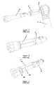
- FIG 3 the perspective view of the shock absorber pin (5') and sleeve (4') of the prior art before inserted into shock absorber holes (6) is illustrated.
- the parts of the pin (5') and the sleeve (4') inserted into the hole (6) are cylindrical.
- the pin (5') is inserted into the sleeve (4') and then they are inserted into the shock absorber hole (6) together.
- Figures 4 and 5 the perspective view of the assembled shock absorber pin (5') and the sleeve (4') is illustrated.
- the recess (4a') on the sleeve (4') and the recess (5a') on the pin (5') are parallel to each other.
- connection style of the sleeve (4) and the pin (5) used in the washing machine (A) of this invention is the same as the connection style of the sleeve (4') and the pin (5') used in the prior art.
- the details of the sleeve (4) and the pin (5) used in the washing machine (A) of this invention is described below.
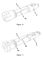
- the recess (4a) on the sleeve (4) is formed at an angel in order for it to have a point contact with the recess (5a) on the pin (5).
- the recess (4a) on the cylindrically formed sleeve (4) is angularly formed with respect to the central axis of the sleeve (4).
- the recess (5a) on the pin (5) is held parallel with respect to the central axis of the pin (5).
- the recess (4a) on the sleeve (4) may be held parallel to the central axis of the sleeve (4)
- the recess (5a) on the pin (5) may be angularly formed with respect to the central axis of the pin (5).
- said point contact of the recess (4a, 5a) edges may be provided.
Landscapes
- Engineering & Computer Science (AREA)
- Textile Engineering (AREA)
- General Engineering & Computer Science (AREA)
- Mechanical Engineering (AREA)
- Main Body Construction Of Washing Machines And Laundry Dryers (AREA)
- Laminated Bodies (AREA)
- Vibration Dampers (AREA)
- Snaps, Bayonet Connections, Set Pins, And Snap Rings (AREA)
- Insertion Pins And Rivets (AREA)
Abstract
Description
- This invention relates to the connection form of the shock absorber with the body and the tub which is used to dampen the vibration created by the turning motion of the drum inside the washing machines.
- In the state of the art, the shock absorbers used in the washing machines are connected to the body and tub of the machine by using shock absorber pins. There are circular shaped holes on both ends of the shock absorber. Said shock absorber pin is inserted into these holes and into circular shaped holes on the body of the machine and the tub associated with these. The pins are subject to wearing since they turn in these holes. Besides they also cause wearing of the holes. That is why shock absorber sleeves are used as the wear element between the holes and the pins. When the sleeves that are placed between the pin and the hole are subject to wear, the space between the pin and the hole gets larger. In such a case, the working space between the pin and the hole is brought back to the desired level by changing the sleeves. Shock absorber sleeves and pins are in the form of hollow cylinders and there are recesses parallel to the main axis of them from end to end on sides. These recesses allow the diameter of the pin and the sleeve to contract a little bit when being inserted into the holes. By this way the pin and the sleeve can be inserted into the desired hole more easily. But while the pin and the sleeve are turning with respect to each other, the recesses on them come across occasionally and the edges of the recesses may wedge. This situation causes undesired sounds to come from the shock absorber pin and sleeve while working.
- In the state of the art of the abovementioned technique, since the recesses on the shock absorber sleeve and the pin are formed parallel to the main axis of the sleeve and the pin, they always contact linearly. In this invention, the recesses on the shock absorber sleeve and the pin contact each other on a point by placing them at an angle with respect to the central axis of the pin and the sleeve or with respect to each other. This prevents the recesses slide passing on each other from generating undesired sounds.
- The goal of this invention is to make the edges of the recesses contact on a point while working by placing the recesses on the shock absorber pins and sleeves used in the washing machines with an angle.
- The representative applications related to the shock absorber sleeve and the pin of this invention are illustrated in the attached figures wherein
-
Figure 1 is the front view of the interior part of the washing machine. -
Figure 2 is the side view of the shock absorber connection. -
Figure 3 is the perspective view of the shock absorber pin and sleeve of the prior art before inserted into shock absorber holes. -
Figure 4 is the perspective view of the shock absorber pin and sleeve of the prior art as assembled together. -
Figure 5 is another perspective view of the shock absorber pin and sleeve of the prior art as assembled together. -
Figure 6 is the perspective view of the shock absorber pin and sleeve of this invention as assembled together. -
Figure 7 is another perspective view of the shock absorber pin and sleeve of this invention as assembled together. - The parts in the figures are each assigned a number and the descriptions of these numbers are given below.
- Washing machine (A)
- Body of the machine (1)
- Tub (2)
- Shock absorber (3)
- Sleeve (4)
- Pin (5)
- Recess (4a)
- Recess (5a)
- Hole (6)
- Sleeve (4')
- Pin (5')
- Recess (4a')
- Recess (5a')
- The washing machine (A) of this invention illustrated in
Figure 1 comprises; at least one shock absorber (3) connected to the body (1) of the machine and the tub (2) inside the body; at least one shock absorber sleeve (4) and pin (5) used on the connection of each of the shock absorbers (3) with the body (1) and the tub (2). InFigure 2 , the side view of the connection of the shock absorber (3) with the body (1) of the machine and the tub (2) is illustrated. As illustrated in this figure, the shock absorber (3) is connected to the holes on the body (1) and the tub (2) by the help of the sleeve (4) and the pin (5). The pin (5) and the sleeve (4) are hollow cylindrical parts. There is one recess on side surfaces of both parts (4, 5) from end to end. - In
Figure 3 , the perspective view of the shock absorber pin (5') and sleeve (4') of the prior art before inserted into shock absorber holes (6) is illustrated. The parts of the pin (5') and the sleeve (4') inserted into the hole (6) are cylindrical. During the installation the pin (5') is inserted into the sleeve (4') and then they are inserted into the shock absorber hole (6) together. InFigures 4 and 5 the perspective view of the assembled shock absorber pin (5') and the sleeve (4') is illustrated. As illustrated in these figures, in the prior art, the recess (4a') on the sleeve (4') and the recess (5a') on the pin (5') are parallel to each other. When the cylindrical forms of these two parts (4', 5') are considered, these recesses (4a', 5a') are also parallel to the central axis of these said parts (4' 5'). Therefore, the edges of the recesses (4a', 5a') have a linear contact while sliding pass on each other at usage. This leads to wedging and undesired sounds to be generated. Hence, the shock absorber sleeve (4) and the pin (5) of this invention have been developed. - The connection style of the sleeve (4) and the pin (5) used in the washing machine (A) of this invention is the same as the connection style of the sleeve (4') and the pin (5') used in the prior art. The details of the sleeve (4) and the pin (5) used in the washing machine (A) of this invention is described below.
- As illustrated in
Figures 6 and 7 , the recess (4a) on the sleeve (4) is formed at an angel in order for it to have a point contact with the recess (5a) on the pin (5). In other words, the recess (4a) on the cylindrically formed sleeve (4) is angularly formed with respect to the central axis of the sleeve (4). In this example, the recess (5a) on the pin (5) is held parallel with respect to the central axis of the pin (5). When the pin (5) is inserted into the sleeve (4), it can be seen that there is an angle between these two recesses (4a' 5a) and the edges of the recesses (4a, 5a) have a point contact with each other. - As an alternative embodiment of the invention, while the recess (4a) on the sleeve (4) is being held parallel to the central axis of the sleeve (4), the recess (5a) on the pin (5) may be angularly formed with respect to the central axis of the pin (5). Or, by forming both recesses (4a, 5a) angularly with respect to said central axes and each other, said point contact of the recess (4a, 5a) edges may be provided.
- During the movement of the sleeve (4) and the pin (5) with respect to each other, the point contact instead of linear contact on the edges of the recesses (4a, 5a) causes to less wedging and less undesired sounds.
Claims (3)
- The washing machine (A) comprising; at least one shock absorber (3) connected to the body (1) of the machine and the tub (2) inside the body; at least one shock absorber sleeve (4) and pin (5) that are used on the connection of each of the shock absorbers (3) with the body (1) and the tub (2), that are hollow cylinders, that have a recess (4a, 5a) on their sides from end to end, and that are inserted into the holes (6) one within the other on the ends of the shock absorber (3); which is characterized in that when the pin (5) is inserted into the sleeve (4), the edge of the recess (4a) on the sleeve (4) is angularly placed with respect to the edge of the recess (5a) on the pin (5).
- A washing machine (A) according to Claim 1 which is characterized in that the recess (4a) on the sleeve (4) is angularly formed with respect to the central axis of the sleeve (4).
- A washing machine (A) according to Claim 1 which is characterized in that the recess (5a) on the pin (5) is angularly formed with respect to the central axis of the pin (5).
Applications Claiming Priority (1)
| Application Number | Priority Date | Filing Date | Title |
|---|---|---|---|
| TR2007/02472A TR200702472A2 (en) | 2007-04-12 | 2007-04-12 | Shock Absorber Sleeve and Pin |
Publications (2)
| Publication Number | Publication Date |
|---|---|
| EP1980661A1 true EP1980661A1 (en) | 2008-10-15 |
| EP1980661B1 EP1980661B1 (en) | 2010-12-01 |
Family
ID=39620087
Family Applications (1)
| Application Number | Title | Priority Date | Filing Date |
|---|---|---|---|
| EP08103472A Not-in-force EP1980661B1 (en) | 2007-04-12 | 2008-04-10 | Shock absorber sleeve and pin |
Country Status (4)
| Country | Link |
|---|---|
| EP (1) | EP1980661B1 (en) |
| AT (1) | ATE490363T1 (en) |
| DE (1) | DE602008003706D1 (en) |
| TR (1) | TR200702472A2 (en) |
Cited By (8)
| Publication number | Priority date | Publication date | Assignee | Title |
|---|---|---|---|---|
| EP2322810A1 (en) * | 2009-11-17 | 2011-05-18 | Miele & Cie. KG | Connection element for a vibration damper of a laundry treatment machine |
| EP2348149A1 (en) * | 2010-01-25 | 2011-07-27 | Bonferraro S.p.A. | Pin for mounting the drum dampers of a washing machine |
| WO2013000899A1 (en) * | 2011-06-27 | 2013-01-03 | Arcelik Anonim Sirketi | A washer/dryer comprising shock absorbers |
| ITTO20121009A1 (en) * | 2012-11-20 | 2014-05-21 | Indesit Co Spa | HOUSEHOLD WASHING MACHINE INCLUDING A PLUG FOR THE COMBINATION OF AT LEAST A SHOCK ABSORBER ELEMENT WITH AN OSCILLATING GROUP, AND ITS PLUG. |
| EP2735633A1 (en) * | 2012-11-20 | 2014-05-28 | Indesit Company S.p.A. | Laundry washing machine for household use comprising a pin for coupling at least one shock-absorbing element to an oscillating assembly, and pin thereof |
| EP2848723A1 (en) | 2013-09-17 | 2015-03-18 | Electrolux Appliances Aktiebolag | Washing laundry machine with damper elements |
| WO2020224850A1 (en) * | 2019-05-03 | 2020-11-12 | Arcelik Anonim Sirketi | A laundry washer or washer/dryer comprising a shock absorber |
| CN113677845A (en) * | 2019-05-27 | 2021-11-19 | 海信(山东)冰箱有限公司 | Washing machine and fastener applied to the washing machine |
Citations (3)
| Publication number | Priority date | Publication date | Assignee | Title |
|---|---|---|---|---|
| DE3511125A1 (en) * | 1984-03-27 | 1985-10-24 | Daido Metal Co. Ltd., Nagoya | WINDING BUSH |
| DE102005008239A1 (en) * | 2004-03-03 | 2005-09-15 | Suspa Holding Gmbh | Connecting device for connecting of vibration damper to washing machine and/or frame of washing machine has fastening sleeve for fitting in eye of damper, and pin for fitting in fastening sleeve |
| WO2007013021A1 (en) * | 2005-07-25 | 2007-02-01 | Arcelik Anonim Sirketi | A washer/dryer |
-
2007
- 2007-04-12 TR TR2007/02472A patent/TR200702472A2/en unknown
-
2008
- 2008-04-10 AT AT08103472T patent/ATE490363T1/en not_active IP Right Cessation
- 2008-04-10 DE DE602008003706T patent/DE602008003706D1/en active Active
- 2008-04-10 EP EP08103472A patent/EP1980661B1/en not_active Not-in-force
Patent Citations (3)
| Publication number | Priority date | Publication date | Assignee | Title |
|---|---|---|---|---|
| DE3511125A1 (en) * | 1984-03-27 | 1985-10-24 | Daido Metal Co. Ltd., Nagoya | WINDING BUSH |
| DE102005008239A1 (en) * | 2004-03-03 | 2005-09-15 | Suspa Holding Gmbh | Connecting device for connecting of vibration damper to washing machine and/or frame of washing machine has fastening sleeve for fitting in eye of damper, and pin for fitting in fastening sleeve |
| WO2007013021A1 (en) * | 2005-07-25 | 2007-02-01 | Arcelik Anonim Sirketi | A washer/dryer |
Cited By (9)
| Publication number | Priority date | Publication date | Assignee | Title |
|---|---|---|---|---|
| EP2322810A1 (en) * | 2009-11-17 | 2011-05-18 | Miele & Cie. KG | Connection element for a vibration damper of a laundry treatment machine |
| EP2348149A1 (en) * | 2010-01-25 | 2011-07-27 | Bonferraro S.p.A. | Pin for mounting the drum dampers of a washing machine |
| WO2013000899A1 (en) * | 2011-06-27 | 2013-01-03 | Arcelik Anonim Sirketi | A washer/dryer comprising shock absorbers |
| ITTO20121009A1 (en) * | 2012-11-20 | 2014-05-21 | Indesit Co Spa | HOUSEHOLD WASHING MACHINE INCLUDING A PLUG FOR THE COMBINATION OF AT LEAST A SHOCK ABSORBER ELEMENT WITH AN OSCILLATING GROUP, AND ITS PLUG. |
| EP2735633A1 (en) * | 2012-11-20 | 2014-05-28 | Indesit Company S.p.A. | Laundry washing machine for household use comprising a pin for coupling at least one shock-absorbing element to an oscillating assembly, and pin thereof |
| EP2848723A1 (en) | 2013-09-17 | 2015-03-18 | Electrolux Appliances Aktiebolag | Washing laundry machine with damper elements |
| WO2020224850A1 (en) * | 2019-05-03 | 2020-11-12 | Arcelik Anonim Sirketi | A laundry washer or washer/dryer comprising a shock absorber |
| CN113677845A (en) * | 2019-05-27 | 2021-11-19 | 海信(山东)冰箱有限公司 | Washing machine and fastener applied to the washing machine |
| CN113677845B (en) * | 2019-05-27 | 2024-06-21 | 海信冰箱有限公司 | Washing machine and fastener used in the washing machine |
Also Published As
| Publication number | Publication date |
|---|---|
| ATE490363T1 (en) | 2010-12-15 |
| DE602008003706D1 (en) | 2011-01-13 |
| EP1980661B1 (en) | 2010-12-01 |
| TR200702472A2 (en) | 2008-11-21 |
Similar Documents
| Publication | Publication Date | Title |
|---|---|---|
| EP1980661B1 (en) | Shock absorber sleeve and pin | |
| CN101678545B (en) | Cartridges for power tools, especially for chisel hammers and/or drill hammers | |
| US9033139B2 (en) | Rod belt for a rod belt conveyor for agricultural machinery | |
| US9702251B2 (en) | Cutting tool assembly including retainer sleeve with retention member | |
| RU2015144291A (en) | IRIS EXPANDER | |
| JP6825006B2 (en) | Side parts, chain links, and energy guide chains | |
| KR101660073B1 (en) | Packing spacer for washing machines | |
| US9587668B2 (en) | Pin retention system | |
| US4961368A (en) | Anchoring element | |
| KR101978592B1 (en) | Axial damper | |
| US20180206639A1 (en) | Shelf frame assembly system and method | |
| ATE487617T1 (en) | LOCKING DEVICE | |
| JP6631070B2 (en) | Transport chain | |
| ITMI962576A1 (en) | DEVICE FOR ANCHORING THE BASKET SHOCK ABSORBER IN WASHING MACHINES OR SIMILAR | |
| US8434829B2 (en) | Method and system of retaining a cutting bit | |
| BR112015023015A2 (en) | END EFFECTOR | |
| KR20180137162A (en) | Superimposed Plate spring for disc coupling | |
| KR101279635B1 (en) | Ball joint for automobile rod arm | |
| EP2348149B1 (en) | Pin for mounting the drum dampers of a washing machine | |
| WO2008087382A3 (en) | Blocks for making model structures | |
| CN214434375U (en) | Detachable soft drill | |
| EP2194292A1 (en) | Cable supporting chain with reduced noise emission | |
| JP2005207435A (en) | Extended spring structure | |
| ES2341377T3 (en) | TWO PIECES AMORTIGUATION AXIS. | |
| KR20180078140A (en) | A Chain |
Legal Events
| Date | Code | Title | Description |
|---|---|---|---|
| PUAI | Public reference made under article 153(3) epc to a published international application that has entered the european phase |
Free format text: ORIGINAL CODE: 0009012 |
|
| 17P | Request for examination filed |
Effective date: 20080415 |
|
| AK | Designated contracting states |
Kind code of ref document: A1 Designated state(s): AT BE BG CH CY CZ DE DK EE ES FI FR GB GR HR HU IE IS IT LI LT LU LV MC MT NL NO PL PT RO SE SI SK TR |
|
| AX | Request for extension of the european patent |
Extension state: AL BA MK RS |
|
| AKX | Designation fees paid |
Designated state(s): AT BE BG CH CY CZ DE DK EE ES FI FR GB GR HR HU IE IS IT LI LT LU LV MC MT NL NO PL PT RO SE SI SK TR |
|
| GRAP | Despatch of communication of intention to grant a patent |
Free format text: ORIGINAL CODE: EPIDOSNIGR1 |
|
| RIN1 | Information on inventor provided before grant (corrected) |
Inventor name: OZKAN, SEMIHVESTEL BEYAZ ESYA SANAYI VE TICARET A. Inventor name: TELCI, YETKIN |
|
| GRAS | Grant fee paid |
Free format text: ORIGINAL CODE: EPIDOSNIGR3 |
|
| GRAA | (expected) grant |
Free format text: ORIGINAL CODE: 0009210 |
|
| AK | Designated contracting states |
Kind code of ref document: B1 Designated state(s): AT BE BG CH CY CZ DE DK EE ES FI FR GB GR HR HU IE IS IT LI LT LU LV MC MT NL NO PL PT RO SE SI SK TR |
|
| REG | Reference to a national code |
Ref country code: GB Ref legal event code: FG4D |
|
| REG | Reference to a national code |
Ref country code: CH Ref legal event code: EP |
|
| REG | Reference to a national code |
Ref country code: IE Ref legal event code: FG4D |
|
| REF | Corresponds to: |
Ref document number: 602008003706 Country of ref document: DE Date of ref document: 20110113 Kind code of ref document: P |
|
| REG | Reference to a national code |
Ref country code: NL Ref legal event code: VDEP Effective date: 20101201 |
|
| PG25 | Lapsed in a contracting state [announced via postgrant information from national office to epo] |
Ref country code: LT Free format text: LAPSE BECAUSE OF FAILURE TO SUBMIT A TRANSLATION OF THE DESCRIPTION OR TO PAY THE FEE WITHIN THE PRESCRIBED TIME-LIMIT Effective date: 20101201 Ref country code: NO Free format text: LAPSE BECAUSE OF FAILURE TO SUBMIT A TRANSLATION OF THE DESCRIPTION OR TO PAY THE FEE WITHIN THE PRESCRIBED TIME-LIMIT Effective date: 20110301 |
|
| LTIE | Lt: invalidation of european patent or patent extension |
Effective date: 20101201 |
|
| PG25 | Lapsed in a contracting state [announced via postgrant information from national office to epo] |
Ref country code: SI Free format text: LAPSE BECAUSE OF FAILURE TO SUBMIT A TRANSLATION OF THE DESCRIPTION OR TO PAY THE FEE WITHIN THE PRESCRIBED TIME-LIMIT Effective date: 20101201 Ref country code: CY Free format text: LAPSE BECAUSE OF FAILURE TO SUBMIT A TRANSLATION OF THE DESCRIPTION OR TO PAY THE FEE WITHIN THE PRESCRIBED TIME-LIMIT Effective date: 20101201 Ref country code: FI Free format text: LAPSE BECAUSE OF FAILURE TO SUBMIT A TRANSLATION OF THE DESCRIPTION OR TO PAY THE FEE WITHIN THE PRESCRIBED TIME-LIMIT Effective date: 20101201 Ref country code: HR Free format text: LAPSE BECAUSE OF FAILURE TO SUBMIT A TRANSLATION OF THE DESCRIPTION OR TO PAY THE FEE WITHIN THE PRESCRIBED TIME-LIMIT Effective date: 20101201 Ref country code: BG Free format text: LAPSE BECAUSE OF FAILURE TO SUBMIT A TRANSLATION OF THE DESCRIPTION OR TO PAY THE FEE WITHIN THE PRESCRIBED TIME-LIMIT Effective date: 20110301 Ref country code: AT Free format text: LAPSE BECAUSE OF FAILURE TO SUBMIT A TRANSLATION OF THE DESCRIPTION OR TO PAY THE FEE WITHIN THE PRESCRIBED TIME-LIMIT Effective date: 20101201 Ref country code: SE Free format text: LAPSE BECAUSE OF FAILURE TO SUBMIT A TRANSLATION OF THE DESCRIPTION OR TO PAY THE FEE WITHIN THE PRESCRIBED TIME-LIMIT Effective date: 20101201 Ref country code: NL Free format text: LAPSE BECAUSE OF FAILURE TO SUBMIT A TRANSLATION OF THE DESCRIPTION OR TO PAY THE FEE WITHIN THE PRESCRIBED TIME-LIMIT Effective date: 20101201 Ref country code: LV Free format text: LAPSE BECAUSE OF FAILURE TO SUBMIT A TRANSLATION OF THE DESCRIPTION OR TO PAY THE FEE WITHIN THE PRESCRIBED TIME-LIMIT Effective date: 20101201 |
|
| PG25 | Lapsed in a contracting state [announced via postgrant information from national office to epo] |
Ref country code: GR Free format text: LAPSE BECAUSE OF FAILURE TO SUBMIT A TRANSLATION OF THE DESCRIPTION OR TO PAY THE FEE WITHIN THE PRESCRIBED TIME-LIMIT Effective date: 20110302 |
|
| PG25 | Lapsed in a contracting state [announced via postgrant information from national office to epo] |
Ref country code: EE Free format text: LAPSE BECAUSE OF FAILURE TO SUBMIT A TRANSLATION OF THE DESCRIPTION OR TO PAY THE FEE WITHIN THE PRESCRIBED TIME-LIMIT Effective date: 20101201 Ref country code: CZ Free format text: LAPSE BECAUSE OF FAILURE TO SUBMIT A TRANSLATION OF THE DESCRIPTION OR TO PAY THE FEE WITHIN THE PRESCRIBED TIME-LIMIT Effective date: 20101201 Ref country code: BE Free format text: LAPSE BECAUSE OF FAILURE TO SUBMIT A TRANSLATION OF THE DESCRIPTION OR TO PAY THE FEE WITHIN THE PRESCRIBED TIME-LIMIT Effective date: 20101201 Ref country code: PT Free format text: LAPSE BECAUSE OF FAILURE TO SUBMIT A TRANSLATION OF THE DESCRIPTION OR TO PAY THE FEE WITHIN THE PRESCRIBED TIME-LIMIT Effective date: 20110401 Ref country code: IS Free format text: LAPSE BECAUSE OF FAILURE TO SUBMIT A TRANSLATION OF THE DESCRIPTION OR TO PAY THE FEE WITHIN THE PRESCRIBED TIME-LIMIT Effective date: 20110401 Ref country code: ES Free format text: LAPSE BECAUSE OF FAILURE TO SUBMIT A TRANSLATION OF THE DESCRIPTION OR TO PAY THE FEE WITHIN THE PRESCRIBED TIME-LIMIT Effective date: 20110312 |
|
| PG25 | Lapsed in a contracting state [announced via postgrant information from national office to epo] |
Ref country code: PL Free format text: LAPSE BECAUSE OF FAILURE TO SUBMIT A TRANSLATION OF THE DESCRIPTION OR TO PAY THE FEE WITHIN THE PRESCRIBED TIME-LIMIT Effective date: 20101201 Ref country code: RO Free format text: LAPSE BECAUSE OF FAILURE TO SUBMIT A TRANSLATION OF THE DESCRIPTION OR TO PAY THE FEE WITHIN THE PRESCRIBED TIME-LIMIT Effective date: 20101201 Ref country code: SK Free format text: LAPSE BECAUSE OF FAILURE TO SUBMIT A TRANSLATION OF THE DESCRIPTION OR TO PAY THE FEE WITHIN THE PRESCRIBED TIME-LIMIT Effective date: 20101201 |
|
| PLBE | No opposition filed within time limit |
Free format text: ORIGINAL CODE: 0009261 |
|
| STAA | Information on the status of an ep patent application or granted ep patent |
Free format text: STATUS: NO OPPOSITION FILED WITHIN TIME LIMIT |
|
| PG25 | Lapsed in a contracting state [announced via postgrant information from national office to epo] |
Ref country code: DK Free format text: LAPSE BECAUSE OF FAILURE TO SUBMIT A TRANSLATION OF THE DESCRIPTION OR TO PAY THE FEE WITHIN THE PRESCRIBED TIME-LIMIT Effective date: 20101201 |
|
| 26N | No opposition filed |
Effective date: 20110902 |
|
| PG25 | Lapsed in a contracting state [announced via postgrant information from national office to epo] |
Ref country code: MC Free format text: LAPSE BECAUSE OF NON-PAYMENT OF DUE FEES Effective date: 20110430 |
|
| REG | Reference to a national code |
Ref country code: DE Ref legal event code: R097 Ref document number: 602008003706 Country of ref document: DE Effective date: 20110902 |
|
| PG25 | Lapsed in a contracting state [announced via postgrant information from national office to epo] |
Ref country code: MT Free format text: LAPSE BECAUSE OF FAILURE TO SUBMIT A TRANSLATION OF THE DESCRIPTION OR TO PAY THE FEE WITHIN THE PRESCRIBED TIME-LIMIT Effective date: 20101201 Ref country code: IT Free format text: LAPSE BECAUSE OF FAILURE TO SUBMIT A TRANSLATION OF THE DESCRIPTION OR TO PAY THE FEE WITHIN THE PRESCRIBED TIME-LIMIT Effective date: 20101201 |
|
| REG | Reference to a national code |
Ref country code: FR Ref legal event code: ST Effective date: 20111230 |
|
| PG25 | Lapsed in a contracting state [announced via postgrant information from national office to epo] |
Ref country code: FR Free format text: LAPSE BECAUSE OF NON-PAYMENT OF DUE FEES Effective date: 20110502 |
|
| REG | Reference to a national code |
Ref country code: IE Ref legal event code: MM4A |
|
| PG25 | Lapsed in a contracting state [announced via postgrant information from national office to epo] |
Ref country code: IE Free format text: LAPSE BECAUSE OF NON-PAYMENT OF DUE FEES Effective date: 20110410 |
|
| PGFP | Annual fee paid to national office [announced via postgrant information from national office to epo] |
Ref country code: TR Payment date: 20120313 Year of fee payment: 5 |
|
| REG | Reference to a national code |
Ref country code: CH Ref legal event code: PL |
|
| GBPC | Gb: european patent ceased through non-payment of renewal fee |
Effective date: 20120410 |
|
| PGFP | Annual fee paid to national office [announced via postgrant information from national office to epo] |
Ref country code: DE Payment date: 20120629 Year of fee payment: 5 |
|
| PG25 | Lapsed in a contracting state [announced via postgrant information from national office to epo] |
Ref country code: LI Free format text: LAPSE BECAUSE OF NON-PAYMENT OF DUE FEES Effective date: 20120430 Ref country code: CH Free format text: LAPSE BECAUSE OF NON-PAYMENT OF DUE FEES Effective date: 20120430 Ref country code: GB Free format text: LAPSE BECAUSE OF NON-PAYMENT OF DUE FEES Effective date: 20120410 |
|
| PG25 | Lapsed in a contracting state [announced via postgrant information from national office to epo] |
Ref country code: LU Free format text: LAPSE BECAUSE OF NON-PAYMENT OF DUE FEES Effective date: 20110410 |
|
| PG25 | Lapsed in a contracting state [announced via postgrant information from national office to epo] |
Ref country code: HU Free format text: LAPSE BECAUSE OF FAILURE TO SUBMIT A TRANSLATION OF THE DESCRIPTION OR TO PAY THE FEE WITHIN THE PRESCRIBED TIME-LIMIT Effective date: 20101201 |
|
| PG25 | Lapsed in a contracting state [announced via postgrant information from national office to epo] |
Ref country code: DE Free format text: LAPSE BECAUSE OF NON-PAYMENT OF DUE FEES Effective date: 20131101 |
|
| REG | Reference to a national code |
Ref country code: DE Ref legal event code: R119 Ref document number: 602008003706 Country of ref document: DE Effective date: 20131101 |
|
| PG25 | Lapsed in a contracting state [announced via postgrant information from national office to epo] |
Ref country code: TR Free format text: LAPSE BECAUSE OF NON-PAYMENT OF DUE FEES Effective date: 20130410 |