EP1979246B1 - Shroud, in particular for corrosion-sensitive freight - Google Patents
Shroud, in particular for corrosion-sensitive freight Download PDFInfo
- Publication number
- EP1979246B1 EP1979246B1 EP07704193A EP07704193A EP1979246B1 EP 1979246 B1 EP1979246 B1 EP 1979246B1 EP 07704193 A EP07704193 A EP 07704193A EP 07704193 A EP07704193 A EP 07704193A EP 1979246 B1 EP1979246 B1 EP 1979246B1
- Authority
- EP
- European Patent Office
- Prior art keywords
- hood
- film
- container
- corrosion inhibitor
- lid
- Prior art date
- Legal status (The legal status is an assumption and is not a legal conclusion. Google has not performed a legal analysis and makes no representation as to the accuracy of the status listed.)
- Not-in-force
Links
- 238000005260 corrosion Methods 0.000 title claims description 59
- 230000007797 corrosion Effects 0.000 title claims description 59
- 239000003112 inhibitor Substances 0.000 claims description 44
- 238000003860 storage Methods 0.000 claims description 42
- 239000004698 Polyethylene Substances 0.000 claims description 8
- -1 polyethylene Polymers 0.000 claims description 8
- 229920000573 polyethylene Polymers 0.000 claims description 8
- 239000000203 mixture Substances 0.000 claims description 3
- 150000002823 nitrates Chemical group 0.000 claims description 3
- 229910019142 PO4 Inorganic materials 0.000 claims description 2
- 150000001412 amines Chemical class 0.000 claims description 2
- 150000001558 benzoic acid derivatives Chemical class 0.000 claims description 2
- 150000001642 boronic acid derivatives Chemical class 0.000 claims description 2
- ZCDOYSPFYFSLEW-UHFFFAOYSA-N chromate(2-) Chemical class [O-][Cr]([O-])(=O)=O ZCDOYSPFYFSLEW-UHFFFAOYSA-N 0.000 claims description 2
- 150000002391 heterocyclic compounds Chemical class 0.000 claims description 2
- 238000012856 packing Methods 0.000 claims description 2
- 235000021317 phosphate Nutrition 0.000 claims description 2
- 150000003013 phosphoric acid derivatives Chemical class 0.000 claims description 2
- 150000004760 silicates Chemical class 0.000 claims description 2
- 239000000843 powder Substances 0.000 claims 1
- 238000003466 welding Methods 0.000 description 8
- 238000001125 extrusion Methods 0.000 description 7
- 239000012530 fluid Substances 0.000 description 7
- 239000006260 foam Substances 0.000 description 6
- 239000011888 foil Substances 0.000 description 6
- 238000004519 manufacturing process Methods 0.000 description 6
- 239000000463 material Substances 0.000 description 6
- 229920003023 plastic Polymers 0.000 description 6
- 239000004033 plastic Substances 0.000 description 6
- 238000004806 packaging method and process Methods 0.000 description 5
- 229920000642 polymer Polymers 0.000 description 5
- 238000009792 diffusion process Methods 0.000 description 4
- 229920000092 linear low density polyethylene Polymers 0.000 description 4
- 239000004707 linear low-density polyethylene Substances 0.000 description 4
- 150000001875 compounds Chemical class 0.000 description 3
- 238000005520 cutting process Methods 0.000 description 3
- 238000000034 method Methods 0.000 description 3
- 239000004712 Metallocene polyethylene (PE-MC) Substances 0.000 description 2
- 239000004708 Very-low-density polyethylene Substances 0.000 description 2
- 239000011324 bead Substances 0.000 description 2
- 239000000969 carrier Substances 0.000 description 2
- 229920001577 copolymer Polymers 0.000 description 2
- 239000008188 pellet Substances 0.000 description 2
- 239000002985 plastic film Substances 0.000 description 2
- 229920006255 plastic film Polymers 0.000 description 2
- 239000000047 product Substances 0.000 description 2
- LPXPTNMVRIOKMN-UHFFFAOYSA-M sodium nitrite Chemical compound [Na+].[O-]N=O LPXPTNMVRIOKMN-UHFFFAOYSA-M 0.000 description 2
- 239000007787 solid Substances 0.000 description 2
- 239000007858 starting material Substances 0.000 description 2
- 229920001866 very low density polyethylene Polymers 0.000 description 2
- XLYOFNOQVPJJNP-UHFFFAOYSA-N water Chemical compound O XLYOFNOQVPJJNP-UHFFFAOYSA-N 0.000 description 2
- 239000004594 Masterbatch (MB) Substances 0.000 description 1
- 239000000853 adhesive Substances 0.000 description 1
- 238000004026 adhesive bonding Methods 0.000 description 1
- 230000001070 adhesive effect Effects 0.000 description 1
- 230000002411 adverse Effects 0.000 description 1
- 239000003570 air Substances 0.000 description 1
- 239000012080 ambient air Substances 0.000 description 1
- 230000009286 beneficial effect Effects 0.000 description 1
- 230000015572 biosynthetic process Effects 0.000 description 1
- 239000012876 carrier material Substances 0.000 description 1
- 238000004040 coloring Methods 0.000 description 1
- NHFDKKSSQWCEES-UHFFFAOYSA-N dihydrogen phosphate;tris(2-hydroxyethyl)azanium Chemical compound OP(O)(O)=O.OCCN(CCO)CCO NHFDKKSSQWCEES-UHFFFAOYSA-N 0.000 description 1
- 238000006073 displacement reaction Methods 0.000 description 1
- 230000000694 effects Effects 0.000 description 1
- 238000010348 incorporation Methods 0.000 description 1
- 230000002401 inhibitory effect Effects 0.000 description 1
- 150000002826 nitrites Chemical class 0.000 description 1
- 239000011148 porous material Substances 0.000 description 1
- 239000002244 precipitate Substances 0.000 description 1
- 238000002360 preparation method Methods 0.000 description 1
- 238000011084 recovery Methods 0.000 description 1
- 239000005060 rubber Substances 0.000 description 1
- 238000007789 sealing Methods 0.000 description 1
- WXMKPNITSTVMEF-UHFFFAOYSA-M sodium benzoate Chemical compound [Na+].[O-]C(=O)C1=CC=CC=C1 WXMKPNITSTVMEF-UHFFFAOYSA-M 0.000 description 1
- 235000010234 sodium benzoate Nutrition 0.000 description 1
- 239000004299 sodium benzoate Substances 0.000 description 1
- 235000010288 sodium nitrite Nutrition 0.000 description 1
- 159000000000 sodium salts Chemical class 0.000 description 1
- 239000000126 substance Substances 0.000 description 1
- 229920001059 synthetic polymer Polymers 0.000 description 1
- 238000009827 uniform distribution Methods 0.000 description 1
Images


Classifications
-
- B—PERFORMING OPERATIONS; TRANSPORTING
- B65—CONVEYING; PACKING; STORING; HANDLING THIN OR FILAMENTARY MATERIAL
- B65D—CONTAINERS FOR STORAGE OR TRANSPORT OF ARTICLES OR MATERIALS, e.g. BAGS, BARRELS, BOTTLES, BOXES, CANS, CARTONS, CRATES, DRUMS, JARS, TANKS, HOPPERS, FORWARDING CONTAINERS; ACCESSORIES, CLOSURES, OR FITTINGS THEREFOR; PACKAGING ELEMENTS; PACKAGES
- B65D75/00—Packages comprising articles or materials partially or wholly enclosed in strips, sheets, blanks, tubes or webs of flexible sheet material, e.g. in folded wrappers
-
- B—PERFORMING OPERATIONS; TRANSPORTING
- B65—CONVEYING; PACKING; STORING; HANDLING THIN OR FILAMENTARY MATERIAL
- B65D—CONTAINERS FOR STORAGE OR TRANSPORT OF ARTICLES OR MATERIALS, e.g. BAGS, BARRELS, BOTTLES, BOXES, CANS, CARTONS, CRATES, DRUMS, JARS, TANKS, HOPPERS, FORWARDING CONTAINERS; ACCESSORIES, CLOSURES, OR FITTINGS THEREFOR; PACKAGING ELEMENTS; PACKAGES
- B65D81/00—Containers, packaging elements, or packages, for contents presenting particular transport or storage problems, or adapted to be used for non-packaging purposes after removal of contents
- B65D81/24—Adaptations for preventing deterioration or decay of contents; Applications to the container or packaging material of food preservatives, fungicides, pesticides or animal repellants
- B65D81/26—Adaptations for preventing deterioration or decay of contents; Applications to the container or packaging material of food preservatives, fungicides, pesticides or animal repellants with provision for draining away, or absorbing, or removing by ventilation, fluids, e.g. exuded by contents; Applications of corrosion inhibitors or desiccators
- B65D81/266—Adaptations for preventing deterioration or decay of contents; Applications to the container or packaging material of food preservatives, fungicides, pesticides or animal repellants with provision for draining away, or absorbing, or removing by ventilation, fluids, e.g. exuded by contents; Applications of corrosion inhibitors or desiccators for absorbing gases, e.g. oxygen absorbers or desiccants
- B65D81/267—Adaptations for preventing deterioration or decay of contents; Applications to the container or packaging material of food preservatives, fungicides, pesticides or animal repellants with provision for draining away, or absorbing, or removing by ventilation, fluids, e.g. exuded by contents; Applications of corrosion inhibitors or desiccators for absorbing gases, e.g. oxygen absorbers or desiccants the absorber being in sheet form
-
- B—PERFORMING OPERATIONS; TRANSPORTING
- B65—CONVEYING; PACKING; STORING; HANDLING THIN OR FILAMENTARY MATERIAL
- B65D—CONTAINERS FOR STORAGE OR TRANSPORT OF ARTICLES OR MATERIALS, e.g. BAGS, BARRELS, BOTTLES, BOXES, CANS, CARTONS, CRATES, DRUMS, JARS, TANKS, HOPPERS, FORWARDING CONTAINERS; ACCESSORIES, CLOSURES, OR FITTINGS THEREFOR; PACKAGING ELEMENTS; PACKAGES
- B65D81/00—Containers, packaging elements, or packages, for contents presenting particular transport or storage problems, or adapted to be used for non-packaging purposes after removal of contents
- B65D81/24—Adaptations for preventing deterioration or decay of contents; Applications to the container or packaging material of food preservatives, fungicides, pesticides or animal repellants
- B65D81/26—Adaptations for preventing deterioration or decay of contents; Applications to the container or packaging material of food preservatives, fungicides, pesticides or animal repellants with provision for draining away, or absorbing, or removing by ventilation, fluids, e.g. exuded by contents; Applications of corrosion inhibitors or desiccators
- B65D81/266—Adaptations for preventing deterioration or decay of contents; Applications to the container or packaging material of food preservatives, fungicides, pesticides or animal repellants with provision for draining away, or absorbing, or removing by ventilation, fluids, e.g. exuded by contents; Applications of corrosion inhibitors or desiccators for absorbing gases, e.g. oxygen absorbers or desiccants
- B65D81/268—Adaptations for preventing deterioration or decay of contents; Applications to the container or packaging material of food preservatives, fungicides, pesticides or animal repellants with provision for draining away, or absorbing, or removing by ventilation, fluids, e.g. exuded by contents; Applications of corrosion inhibitors or desiccators for absorbing gases, e.g. oxygen absorbers or desiccants the absorber being enclosed in a small pack, e.g. bag, included in the package
-
- B—PERFORMING OPERATIONS; TRANSPORTING
- B32—LAYERED PRODUCTS
- B32B—LAYERED PRODUCTS, i.e. PRODUCTS BUILT-UP OF STRATA OF FLAT OR NON-FLAT, e.g. CELLULAR OR HONEYCOMB, FORM
- B32B2307/00—Properties of the layers or laminate
- B32B2307/70—Other properties
- B32B2307/752—Corrosion inhibitor
-
- B—PERFORMING OPERATIONS; TRANSPORTING
- B32—LAYERED PRODUCTS
- B32B—LAYERED PRODUCTS, i.e. PRODUCTS BUILT-UP OF STRATA OF FLAT OR NON-FLAT, e.g. CELLULAR OR HONEYCOMB, FORM
- B32B2439/00—Containers; Receptacles
-
- B—PERFORMING OPERATIONS; TRANSPORTING
- B32—LAYERED PRODUCTS
- B32B—LAYERED PRODUCTS, i.e. PRODUCTS BUILT-UP OF STRATA OF FLAT OR NON-FLAT, e.g. CELLULAR OR HONEYCOMB, FORM
- B32B37/00—Methods or apparatus for laminating, e.g. by curing or by ultrasonic bonding
- B32B37/14—Methods or apparatus for laminating, e.g. by curing or by ultrasonic bonding characterised by the properties of the layers
- B32B37/15—Methods or apparatus for laminating, e.g. by curing or by ultrasonic bonding characterised by the properties of the layers with at least one layer being manufactured and immediately laminated before reaching its stable state, e.g. in which a layer is extruded and laminated while in semi-molten state
- B32B37/153—Methods or apparatus for laminating, e.g. by curing or by ultrasonic bonding characterised by the properties of the layers with at least one layer being manufactured and immediately laminated before reaching its stable state, e.g. in which a layer is extruded and laminated while in semi-molten state at least one layer is extruded and immediately laminated while in semi-molten state
-
- B—PERFORMING OPERATIONS; TRANSPORTING
- B65—CONVEYING; PACKING; STORING; HANDLING THIN OR FILAMENTARY MATERIAL
- B65D—CONTAINERS FOR STORAGE OR TRANSPORT OF ARTICLES OR MATERIALS, e.g. BAGS, BARRELS, BOTTLES, BOXES, CANS, CARTONS, CRATES, DRUMS, JARS, TANKS, HOPPERS, FORWARDING CONTAINERS; ACCESSORIES, CLOSURES, OR FITTINGS THEREFOR; PACKAGING ELEMENTS; PACKAGES
- B65D2203/00—Decoration means, markings, information elements, contents indicators
- B65D2203/10—Transponders
Definitions
- the present invention relates to a hood according to the preamble of claim 1, in particular for sealing storage or transport containers for receiving corrosion-sensitive charge.
- Containers for the storage and / or transport of corrosion-sensitive cargo are known for various applications.
- such containers are used in large numbers in order to enable a rational and automatable storage of a variety of different parts.
- Such containers also referred to as small load carriers (KLT)
- KLT small load carriers
- Such containers also referred to as small load carriers (KLT)
- KLT small load carriers
- To seal such containers are both hoods of flexible films as well as rigid lid.
- VCI Volatile Corrosion Inhibitors
- An RFID-enabled container which comprises a container blank and an RF transponder which is arranged on the container blank so that it is not visible from the outside when the container is set up.
- the object of the present invention is to provide a hood with the help of which a quick and easy identification of the charge located in the container is made possible.
- a hood according to claim 1 characterized in that the hood comprises an electronic memory element.
- Hoods with an electronic memory element can also be used for the packaging of general cargo, such as motors or gearboxes. With the help of the memory element, the content be identified at any time without the packaging being opened, thereby impairing the corrosion protection. As a result, for example, inventory or customs clearance of goods are much easier.
- the storage element can be used to store any type of relevant data, in particular the type and quantity of the contents of the container, exact type designations, the date of storage or the destination during transport.
- the storage element can also serve to track the transport path of the goods.
- An electronic memory element makes it possible to store a large amount of data in a very small space, for example compared to a label.
- an electronic memory chip can be read out and / or written by machine so that these processes can also be carried out automatically.
- the memory element is preferably read without contact. This is the case in particular with the aid of so-called RFID chips (Radio Frequency IDentification), which can be read out by radio.
- RFID chips Radio Frequency IDentification
- the memory element can also be written without contact, so that the data stored in the element can be updated if necessary in a simple manner. This applies in particular to the above-mentioned lifetime of the corrosion protection, which is affected by repeated opening of the container and which can then be updated accordingly with each opening.
- the storage element is preferably permanently connected to the hood. This can prevent data loss by removing or dropping the memory element.
- the storage element is welded onto the hood. A detachment of the memory element is thereby virtually eliminated.
- the storage element may in particular also be welded in a weld seam of the hood.
- the storage element can be glued to the hood.
- a sticking can be particularly beneficial if a Aufschwei- ⁇ en due to the materials of the storage element and the hood is not possible.
- the electronic memory element preferably comprises an electronic memory chip and a carrier, on which the memory chip is arranged.
- the memory chip and / or also an RFID chip can be enclosed in the carrier or adhered to it.
- the carrier itself is in turn preferably glued or welded onto the hood.
- a hood based on polyethylene such a support is preferably produced based on polyethylene.
- the electronic storage element is arranged on the container itself.
- the subject of the invention is therefore also a storage or transport container of the type mentioned, which comprises an electronic storage element.
- the arrangement of the storage element on the container in the same manner and according to the same embodiments, as described in connection with the hood according to the invention.
- the present invention relates to a hood of the type mentioned, which is made of a film containing at least one volatile corrosion inhibitor.
- the hood according to the invention which defines an interior space and has an opening, is slipped with its opening over the storage or transport container.
- the container is thereby closed, and at the same time the corrosion inhibitor contained in the film is delivered to the interior of the container.
- corrosion protection of the charge contained in the container is ensured even during a longer storage time.
- the corrosion inhibitor contained in the film is exhausted, the hood is replaced.
- the remaining life of the corrosion inhibitor can be determined at any time.
- hood is made of a film containing corrosion inhibitor (s), which is elastically extensible.
- a film is referred to as elastically extensible if, after stretching of the film, at least predominantly a return to the original dimension takes place.
- Hoods made of an elastically stretchable film have significant advantages over the previously used VCI-containing hoods.
- the elastic hood according to the invention preferably consists only of the film and can thus be produced in a simple manner by machine. This leads to a significant cost savings compared to the previously known hoods.
- the elastic hood according to the invention When closing containers or when packing piece goods for the purpose of storage or transport, the elastic hood according to the invention is usually stretched, so that it rests tightly on the packaged object due to the high elastic restoring force. On the one hand, this reduces the risk of the film sticking out of the object and being damaged during transport, and, on the other hand, ensuring high tightness of the packaging. Especially from the point of view of corrosion protection, it is desirable that the packaging is as airtight as possible, which is made possible to a high degree by the use of an elastic hood according to the invention.
- the elongation of the film along the opening of the hood is usually up to 10% (so-called use stretch).
- the tightness of the hood against air and water vapor can be further increased by the fact that along the opening of the hood by pushing together the film forms a bead, which exerts a correspondingly greater pressure on the container.
- the extensibility of the film, from which the elastic hood according to the invention is made can be characterized inter alia by their elongation at break, that is, by their maximum elongation to the crack.
- the elongation at break of the film is 300% or more, more preferably 600% or more.
- the recovery strain is preferably 50% or more, more preferably 100% or more.
- the film is further distinguished by the fact that its elasticity or resilience in elastically stretched state over a longer period of time, typically at least 8 to 10 weeks, is maintained.
- the thickness of the film is preferably in the range from 40 to 150 ⁇ m, in particular in the range from 50 to 80 ⁇ m.
- the special properties of the elastically stretchable film also offer the advantage that the hood produced therefrom has a high puncture resistance perpendicular to the material plane.
- the elastic hood according to the invention thus offers good protection against external mechanical effects on the packaged item.
- the elastically extensible film is preferably a plastic film which is produced on the basis of a synthetic polymer.
- different polymers can be considered as starting material, with which the mechanical properties described above can be realized.
- the film is made on the basis of polyethylene or polyethylene copolymers. These polymers are very suitable for the production of films, in particular by means of the extrusion process.
- Particularly suitable starting materials for the film are linear low-density polyethylene (LLD-PE), very low-density polyethylene (VLD-PE) or corresponding copolymers. Due to their molecular structure, these polymers lead to films with a high elastic stretchability.
- the polyethylenes used may additionally be metallocene polyethylene (mPE) or corresponding copolymers.
- the film comprises two or more layers.
- the at least one volatile corrosion inhibitor is contained at least in that layer of the film which faces the interior of the hood, so that the corrosion inhibitor is discharged exclusively or predominantly in the direction of the container contents or the packaged piece goods and not to the environment.
- multilayer films are also particularly advantageous because one or more additional layers which contain no corrosion inhibitor, the inventive elastic extensibility and the high tensile strength of the film can be further improved. These properties result primarily from the molecular structure of the film, which by the addition of the corrosion inhibitor is affected in the appropriate position. Layers without corrosion inhibitor also contribute in particular to a high airtightness and water vapor tightness of the film.
- the layers of a two- or multi-layer elastically extensible film are preferably coextruded.
- the coextrusion of multilayer films can be realized by means of various extrusion processes, in particular by blown film extrusion.
- the at least one volatile corrosion inhibitor is preferably present in finely powdered form in the film. This can be achieved, in particular, by adding the at least one volatile corrosion inhibitor to the polymer melt prior to extrusion of the film in polymer-bound form (compounded). This so-called masterbatch ensures the finest possible and uniform distribution of the at least one corrosion inhibitor in the film.
- the at least one volatile corrosion inhibitor is selected from nitrates, nitrites, phosphates, silicates, borates, chromates, molybdates, amines, benzoates, heterocyclic compounds, and mixtures thereof.
- the sodium salts of the compounds mentioned are preferably used in each case.
- the film from which the hood according to the invention is made is advantageously colored translucent. Such a coloring can serve for the identification of packaged objects, without having to dispense with a transparency of the hood.
- the hood of the invention may be made of one or more pieces of film, wherein the film piece (s) is folded and / or superposed and congruent edges of the film piece (s) are partially welded together.
- the non-welded edges of the foil pieces (s) form the opening with which the hood can be pulled over the container.
- the seams formed during welding offer a preferred possibility of connecting the electronic storage element to the hood by welding the storage element into a weld seam of the hood.
- the hood In order to avoid undesired protrusion of the hood, it is preferred if its shape is adapted to the shape of the storage or transport container. In principle, different shapes are conceivable for such containers, for example a cuboid or a cylindrical shape.
- the hood also has a cuboid shape. This can be achieved in particular in that the film is folded on the opposite side of the opening of the hood in the direction of the interior.
- the hood is made of a film tube, wherein the film for producing the hood along two opposite areas along the longitudinal axis of the tube is folded in the direction of the interior of the tube, and wherein the film tube is welded at one end, that the folded regions of the film with the non-folded portions of the film are four-layer welded.
- Hoods of this type are particularly easy to produce by folding in a continuous film tube produced by blown film extrusion as described above and then cutting at predetermined intervals and welding along the cutting edge. All work steps can be carried out continuously and automatically.
- the hood produced in this way can be brought into a cuboid shape, wherein the previously folded-in areas of the film form two opposite sides of the hood.
- the weld seam then runs along a center line of the side of the hood opposite the opening, wherein the sections of the previously folded-in regions adjacent to the weld are folded in the direction of the interior of the hood in such a way that two triangular regions in which the film comes to lie three-fold, be formed.
- a similar hood can, alternatively to the use of a hose, also be made of two equal rectangular pieces of film along in each case three of their edges are welded together to form a central weld and two subsequent side welds; the hood having two central fold lines, each running at an identical distance to both sides parallel to the central weld, having two lateral fold lines each running the same identical distance to both sides parallel to the side welds, and having four diagonal fold lines from the four intersections of the middle fold lines with the lateral fold lines to the respective adjacent end of the middle weld run; wherein the film is folded by 180 ° along the diagonal fold lines and along those portions of the lateral fold lines that lie between the intersections with the middle fold lines, so that in each case two triangular foil areas come to lie congruently on one another; and wherein the film is folded by 90 ° along the central fold lines and along those portions of the side fold lines which are outside the intersection with the central fold lines, so that the hood has a parallelepiped shape.
- the present invention also relates to the use of a hood as described above for closing storage or transport containers.
- a lid is understood in particular to mean a substantially rigid element with which the container can be detachably closed.
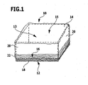
- FIG. 1 A first embodiment of a hood according to the invention is shown in perspective in FIG. 1 and denoted there by 10. Furthermore, the shows FIG. 1 a storage or transport container 12, a receiving space 13th defined and having an opening 14 which is closed by the hood 10. The parts of the container 12, which are covered by the hood 10, are shown here for the sake of clarity with dashed lines.
- the hood 10 is preferably transparent.
- Both the container 12 and the hood 10 have a substantially cuboid shape.
- the container 12 may be, for example, a small load carrier (KLT), as it often comes in the context of industrial storage used.
- KLT small load carrier
- the hood 10 is made of a film which comprises at least one volatile corrosion inhibitor and is elastically extensible.
- this film may be made of a linear low-density polyethylene (LLD-PE).
- LLD-PE linear low-density polyethylene
- the film has a high elastic elasticity and restoring force.
- the film is a three-layer, coextruded film having an elongation at break in the range of 650 to 750% and an elastic elongation in the range of 50 to 100%.
- the at least one corrosion inhibitor is contained only in that position of the film, which faces the interior 15 of the hood 10.
- the corrosion inhibitor may be the compounds mentioned above or mixtures thereof, such as sodium benzoate, sodium nitrite or triethanolamine phosphate.
- the circumference of the hood 10 along its opening 16, in the unstretched state of the film is smaller than the circumference of the container 12 in a plane parallel to its bottom surface 18. Therefore, the hood 10 is located on the side walls 20 of the container 12 due to the elastic restoring force the film firmly. Furthermore, the height of the hood 10, that is, the dimension selected perpendicular to the bottom surface 18, greater than the height of the side walls 20, so that the film along the opening 16 of the hood 10 by gathering a bead 22 forms. This additionally ensures an airtight closure of the container 12.
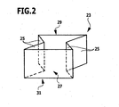
- the hood 10 may be made of a film tube 23, which in the FIG. 2 is shown schematically.
- a film tube 23 can be produced in particular by means of blown film extrusion.
- the film is first folded along two opposite regions 25 along the longitudinal axis of the tube 23 in the direction of the interior 27 of the tube 23. Subsequently, the film tube 23 is welded at one end 29 such that the folded-in regions 25 of the film are welded in four layers to the non-folded regions of the film (in the US Pat FIG. 2 not shown).
- the opposite, non-welded end 31 of the tube 23 forms the opening 16 of the hood 10th
- the extrusion of a continuous film tube, the cutting of individual film tubes 23 and the welding at their ends 29 can be carried out continuously and automatically.
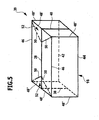
- the film tube 23 welded in this way can be brought into the essentially parallelepiped shape of the hood 10, as shown in FIG FIG. 3 is shown.
- the previously folded-in areas 25 of the film form two opposite sides 25 of the hood 10.
- the weld 33 formed by welding the end 29 of the hose 23 extends along a center line of the opening 14 opposite side 35 of the hood 10, wherein the weld 33 adjacent Sections of the previously folded-in areas 25 are folded in the direction of the interior 15 of the hood, that two triangular areas 37, in which the film comes to rest three-fold, are formed.
- a second embodiment of a hood according to the invention with a substantially cuboid shape can also be produced by welding and folding two rectangular pieces of film, as described below with reference to FIGS FIGS. 4 and 5 is described.
- FIG. 5 shows a perspective view of the second embodiment of the hood, which is designated as a whole by 39, including the welds and folded portions of the film.
- the film pieces 24 and 26 used for the production of the hood 39 are in the FIG. 4 shown in outstretched form.
- the two equal-sized, rectangular pieces are first welded together along a central weld seam 28 at one of their edges.
- the edges 30 and 32 of the first piece of film 24 adjacent to the central weld seam 28 are also welded to the corresponding edges 34 and 36 of the second piece of film 26, forming the in FIG. 3 shown side welds 38 and 40.
- the opposite of the central weld 28 edges 42 and 44 form the opening 16 of the hood 39th
- the film pieces 24 and 26 are folded to form the hood 39 along the following folding lines (in FIG. 4 shown by dashed lines), wherein the course of the fold lines refers to the spread in a plane pieces of film 24 and 26: two middle fold lines 46 each at an identical distance to both sides parallel to the central weld 28, two lateral fold lines 48 each extend in the same identical distance to both sides parallel to the lateral welds 38 and 40, and four diagonal fold lines 50 each extend from the four intersections of the middle Fold lines 46 with the side fold lines 48 to the respective adjacent end of the central weld 28th
- the film is folded by 180 ° so that two triangular foil areas 52 come to lie congruently on each other.
- the film is folded by 90 °, so that the hood 39, the in FIG. 5 having shown cuboid shape.
- the sections 48 "form the four edges of the hood 39 perpendicular to the opening 16, and the sections 48 'form two mutually parallel edges of the hood 39 opposite the opening 16. Two further parallel edges, which are opposite the opening 16 and perpendicular to the sections 48 'are formed by those portions 46' of the middle fold lines 46 which lie between the intersections with the lateral fold lines 48.
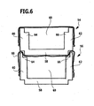
- FIG. 6 schematically shows two stacked containers 54 and 56 in lateral cross-section. The slipping of the upper container 54 is prevented by a projection 58 engages on the underside of the container 54 between the side walls 60 and 62 of the lower container 56 and thereby rests on projections 64 and 66.
- the lower container 56 is closed here with a hood 68, which corresponds to the hood 10 of the first embodiment.
- the hood 68 is thereby pressed by the projection 58 of the container 54 partially in the direction of the receiving space 69 of the container 56, which is easily possible due to the elastic extensibility of the film used for the hood 68 without the risk that the film tears.
- the same advantage also results in other configurations of the positive connection between the containers, since this will always be associated with stretching of the film.
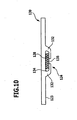
- a third embodiment of a hood according to the invention is in the FIG. 7 shown in perspective and designated there as a whole with 70.
- the hood 70 is made of a film containing at least one volatile corrosion inhibitor, as in the hood 10 of the first embodiment.
- the hood 70 includes an electronic memory element 72 that is welded into a weld 74 of the hood 70.
- various data can be stored, which with respect to a the hood 70 are closed container relevant, in particular type and amount of the contents of the container, the date of storage, etc.
- the memory element 72 may comprise, for example, an RFID chip which can be read out and written by radio without contact. In this way, different containers can be uniquely identified at any time and the relevant data updated as needed.
- the electronic memory element 72 may also be connected to the foil in another way.
- a memory chip may be glued directly to the foil or secured in or on a carrier by welding or gluing.
- a carrier can in turn be glued or welded onto the film, wherein the film and the carrier are preferably made of the same material, in particular polyethylene.
- FIG. 8 is a container that can be used for storage and transport of small cargo, shown schematically and designated 110 as a whole.
- the container 110 which is preferably made of plastic, has a cuboid shape and comprises a rectangular bottom surface 112 and four of the bottom surface 112 vertically upwardly extending, rectangular, in pairs parallel side walls 114.
- the container 10 defines an interior 116 and has an opening 117 which is formed by the upper edges of the side walls 114.
- a lid 118 suitable for closing the opening 117 of the container 110 is shown in FIG FIG. 8 shown in a slightly raised position above the container 110.
- the lid 118 is substantially rectangular and is preferably made of a plastic material, as well as the container 110.
- a holding device and / or a receiving space, which are arranged on the lid 118, are due to the selected perspective in the FIG. 8 not visible. Possible embodiments of the lid 118 will be apparent from the four embodiments, which in the FIGS. 9 to 12 are shown and described below.
- the figures each show a lid and optionally a container in a sectional view, wherein the sectional plane corresponds to a plane of symmetry of the container 110.
- FIG. 9 A corresponding sectional view of the container 110, the opening 117 is closed with a first embodiment of a lid 120 is in the FIG. 9 shown.
- the cover 120 rests on strip-shaped projections 122, which are integrally formed on at least two opposite side walls 114 and parallel to the opening 117 forming edges of the side walls 114 extend.
- the projections 122 are arranged in a distance approximately corresponding to the thickness of the cover 120 to the opening 117, so that the lid terminates approximately flush with the side walls 114 and the interior 116 of the container 110 is limited upwards.
- a holding device 124 is arranged at the interior 116 of the lid 120 facing side, that is the inside 123.
- This holding device 124 comprises two clamping elements 126 in the form of cuboid or strip-shaped projections, which are arranged at a distance from one another and which protrude at a right angle from the inside 123 of the lid 120.
- the clamping elements 126 define a receiving space 127 lying between them, wherein a fluid connection 129 between this receiving space 127 and the interior 116 of the container 110 by the unlocked, is defined from the inside 123 facing away side of the receiving space 127.
- a support member 128 containing at least one volatile corrosion inhibitor is arranged in the receiving space 127.
- this carrier element 128, the embodiment shown is a foam which is dimensioned in such a way that it is held non-positively, ie under tension, between the two clamping elements 126.
- the corrosion inhibitor contained in the foam can diffuse out of the foam through the pore structure of the foam, diffuse further through the fluid connection 129 into the interior 116 of the container 110 and distribute itself uniformly there.
- another carrier element may also be used, for example a tablet, a pellet or the like, with a corrosion inhibitor contained therein.
- the size of the tablet and the distance between the clamping elements 126 are each chosen so that the tablet is inserted under tension into the receiving space 127 and frictionally held between the clamping elements 126.
- the corrosion inhibitor can diffuse out of the support element 128, ie the tablet, which is in the holding position, and out of the container 116 via the fluid connection 129 into the interior 116 of the container 110.
- the holding device 124 also comprises two clamping elements 132.
- the clamping elements 132 are spaced from each other on the inside 123 of the lid 130 and have an approximately L-shaped configuration. First portions of the clamping elements 132 extend approximately at right angles from the inside 123 of the lid 130 away. Subsequent second subregions of the clamping elements 132 extend parallel to the lid, wherein free ends of the second portions of the two clamping elements 132 are oriented toward each other.
- the clamping elements 132 define a receiving space 134 lying between them and the inside 123 of the cover 130, which has a fluid connection 135 in the form of an outlet gap to the interior of a container, not shown in the figure.
- a support member 128 which is inserted between the two clamping elements 132 is held in this way in the receiving space 134 between the cover 130 and the clamping elements 132.
- One or more corrosion inhibitors contained in the support member 128 may diffuse via the fluid connection 135 into the interior of the container.
- the clamping elements 132 are, like the clamping elements 126 of the first embodiment, preferably formed integrally with the cover 130.
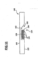
- a third embodiment of a lid is in the FIG. 11 shown in cross-section and designated 140 there.
- the lid 140 is substantially solid, but has an approximately cuboid recess, which defines a receiving space 142 for a support member 128. While the receiving space 142 is completely closed towards the outside 143 of the lid, it is bounded towards the inside 123 by a support element 144, which is formed integrally with the lid 140.
- the support element 144 forms an approximately rectangular surface, runs parallel to the inside 123 of the lid 140 and terminates flush with this. Along at least one of its four edges, the support element 144 is not connected to the lid 140, but spaced therefrom, so that a filling opening 145 of the receiving space 142 is formed. Through the filling opening 145, the support member 128 between the support member 144 and the cover 140, that is, in the receiving space 142, can be inserted.
- the support element 144 serves as a holding device 124.
- the support element 144 has openings 146.
- the openings 146 in addition to the filling opening 145, the fluid connection between the receiving space 142 and the interior 116 of the container 110. This may be a few openings 146, as in the FIG. 11 represented, or a variety of breakthroughs. It is particularly advantageous if the support element 144 is designed in the form of a grid.
- the carrier element 128 can also be, for example, a foam, a tablet or a pellet. Likewise, however, the carrier element 128 may also include, for example, a plastic sheath through which a corrosion inhibitor contained therein may diffuse.
- the lid 140 Due to the formation of the receiving space 142 in a recess of the lid 140, the lid 140 has an overall substantially planar shape, whereby a good stackability of a plurality of similar lid 140 is favored.
- the latter is substantially gas-tight enclosure, since the openings 146 and the filling opening 145 are closed by the outside 143 of the underlying lid 140. This will cause outdiffusion of the corrosion inhibitor during storage of the lid 140 largely prevented.
- a fourth embodiment of a lid is in the FIG. 12 shown in cross-section and designated there by 150.
- a receiving space 154 is likewise provided, which is formed by a substantially parallelepiped-shaped recess in the otherwise solid lid 150.
- the substantially rectangular support element 144 is formed integrally with the cover 150 and, in contrast to the third embodiment, connected to the cover 150 along all four edges.
- a fluid connection between the receiving space 154 and the interior of the container is therefore formed only by the apertures 146 provided in the support element 154.
- the support element 154 may be formed in this case in the form of a grid.
- the receiving space 154 Towards the outside 143 of the cover 150, the receiving space 154 has a filling opening 152, which is essentially rectangular and which lies opposite the support element 144. Through the filling opening 152, a carrier element 128, which substantially fills the receiving space 154, can be easily inserted into it.
- the filling opening 152 can be closed by a closure element 156 in the form of a pivotable flap, which is articulated on the outside 143 of the lid 150. In the closed position of the flap, outward diffusion of the corrosion inhibitor is prevented.
- the cover 150 offers the advantage that a carrier element 128 with depleted corrosion inhibitor can be exchanged through the filling opening 152 without the container having to be opened.
- the lid is a rigid closure member made of a substantially inflexible plastic material. Nevertheless, a receiving space and / or a holding device, as described above, can also be provided on the side of the hood facing the interior of the container, even in the case of a hood according to the invention which is entirely or partially made of a flexible film.
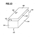
- FIG. 13 shows a perspective view of the already in FIG. 8 shown container 110 with a fifth embodiment of a lid, which is shown in a slightly raised position above the container 110 and designated by 160.
- the lid 160 may optionally include a holding device and / or a receiving space as in the covers 120, 130, 140 or 150.
- the lid 160 includes an electronic storage element 162 which is glued or welded on the outside of the lid 160.
- various data relevant to the container 110 may be stored, for example, the type and amount of the load and / or the date of storage.
- the storage element 162 can also store the use date of a corrosion inhibitor which is present in a carrier element on the lid 160 or which is present in the container 110 in any other form.
- the memory element 162 comprises a carrier 164, in which an electronic memory chip 166 is welded.
- the carrier 164 is preferably made of plastic, in particular of the same plastic material as the lid 160, whereby it is possible to weld it onto the lid 160. Likewise, an adhesive bond between the memory chip 166 and the carrier 164 and between the carrier 164 and the lid 160 is possible.
- the memory element 162 may further comprise an RFID chip 168, which allows a non-contact readout of the stored data via radio.
- the memory chip 166 and the RFID chip 168 may also be formed as a unit. By using RFID chips, different containers can be identified quickly and easily and the relevant data can be updated as needed.
- the electronic storage element may also be provided on the container 110, for example on one of the side walls 114 or on the bottom surface 112.
Landscapes
- Engineering & Computer Science (AREA)
- Mechanical Engineering (AREA)
- Food Science & Technology (AREA)
- Packages (AREA)
Description
Die vorliegende Erfindung betrifft eine Haube gemäß dem Oberbegriff Anspruchs 1, insbesondere zum Verschließen von Lager- oder Transportbehältern für die Aufnahme von korrosionsempfindlicher Ladung.The present invention relates to a hood according to the preamble of
Behälter für die Lagerung und/oder den Transport von korrosionsempfindlicher Ladung sind für verschiedene Einsatzbereiche bekannt. Im Rahmen der industriellen Fertigung, zum Beispiel in der Automobilindustrie, kommen solche Behälter in großer Stückzahl zum Einsatz, um eine rationelle und automatisierbare Lagerhaltung einer Vielzahl von verschiedenen Teilen zu ermöglichen. Solche auch als Kleinladungsträger (KLT) bezeichneten Behälter weisen in der Regel die Form eines Quaders auf, der an der Oberseite offen ist. Zum Verschließen derartiger Behälter eignen sich sowohl Hauben aus flexiblen Folien als auch steife Deckel.Containers for the storage and / or transport of corrosion-sensitive cargo are known for various applications. In the context of industrial manufacturing, for example in the automotive industry, such containers are used in large numbers in order to enable a rational and automatable storage of a variety of different parts. Such containers, also referred to as small load carriers (KLT), generally have the shape of a cuboid, which is open at the top. To seal such containers are both hoods of flexible films as well as rigid lid.
Soweit es sich bei der Ladung der Behälter um metallische Erzeugnisse handelt, werden flüchtige Korrosionsinhibitoren (VCI, Volatile Corrosion Inhibitors) eingesetzt, um diese während der Lagerung oder des Transports gegen atmosphärische Korrosion zu schützen. Bei den VCI handelt es sich um chemische Substanzen, die bei Raumtemperatur sublimieren und sich auf der Oberfläche der zu schützenden Erzeugnisse niederschlagen, um dort ihre korrosionsinhibierende Wirkung zu entfalten.As far as the loading of the containers is metallic, Volatile Corrosion Inhibitors (VCI) are used to protect them against atmospheric corrosion during storage or transport. The VCI are chemical substances which sublime at room temperature and precipitate on the surface of the products to be protected in order to develop their corrosion-inhibiting action.
Insbesondere bei umfangreichen Lagerhaltungen mit einer großen Zahl an verschiedenen Erzeugnissen und/oder Einzelteilen stellt es häufig ein Problem dar, den Inhalt verschiedener Behälter jederzeit eindeutig identifizieren zu können. Sowohl das Öffnen der Behälter, um deren Inhalt festzustellen, als auch das Vorsehen einer Beschriftung sind umständliche Maßnahmen, die jeweils nur manuell durchgeführt werden können. Darüber hinaus führt das wiederholte Öffnen von eingelagerten Behältern dazu, dass ein Teil des flüchtigen Korrosionsinhibitors aus dem Behälter entweicht und/oder Umgebungsluft in den Behälter eindringt, so dass der Korrosionsschutz beeinträchtigt wird.Especially with extensive warehousing with a large number of different products and / or individual parts, it is often a problem to be able to identify the content of different containers at any time clearly. Both the opening of the container to determine its content, as well as the provision of a label are cumbersome measures that can be performed only manually. In addition, the repeated opening of stored containers results in some of the volatile corrosion inhibitor escaping from the container and / or ambient air entering the container, thus adversely affecting corrosion protection.
In der
Aufgabe der vorliegenden Erfindung ist es, eine Haube bereitzustellen, mit deren/dessen Hilfe eine schnelle und einfache Identifikation der in dem Behälter befindlichen Ladung ermöglicht wird.The object of the present invention is to provide a hood with the help of which a quick and easy identification of the charge located in the container is made possible.
Diese Aufgabe wird bei einer Haube gemäß Anspruch 1 dadurch gelöst, dass die Haube ein elektronisches Speicherelement umfasst.This object is achieved in a hood according to
Besondere Ausgestaltungen und Vorteile der erfindungsgemäßen Haube, die sich im Hinblick auf den Einsatz eines flüchtigen Korrosionsinhibitors ergeben, werden weiter unter noch im Detail ausgeführt. Im Folgenden soll zunächst auf die Vorteile des elektronischen Speicherelements eingegangen werden.Particular embodiments and advantages of the hood according to the invention, which arise with regard to the use of a volatile corrosion inhibitor are further explained below in more detail. In the following, the advantages of the electronic memory element will first be discussed.
Durch das Vorsehen eines solchen Speicherelements in oder an den Hauben, die zum Verschließen von Lager- oder Transportbehältern verwendet werden, wird eine sehr einfache, sichere und umfangreiche Identifikation der Ladung ermöglicht. Hauben mit einem elektronischen Speicherelement können darüber hinaus auch zur Verpackung von Stückgut, z.B. Motoren oder Getrieben, eingesetzt werden. Mit Hilfe des Speicherelements kann der Inhalt jederzeit identifiziert werden, ohne dass die Verpackung geöffnet und dadurch der Korrosionsschutz beeinträchtigt wird. Dadurch werden beispielsweise Inventur oder Zollabfertigung der Waren wesentlich erleichtert.By providing such a storage element in or on the hoods which are used to seal storage or transport containers, a very simple, secure and extensive identification of the charge is made possible. Hoods with an electronic memory element can also be used for the packaging of general cargo, such as motors or gearboxes. With the help of the memory element, the content be identified at any time without the packaging being opened, thereby impairing the corrosion protection. As a result, for example, inventory or customs clearance of goods are much easier.
Das Speicherelement kann genutzt werden, um jegliche Art von relevanten Daten zu speichern, insbesondere Art und Menge des Inhalts des Behälters, genaue Typenbezeichnungen, das Datum der Einlagerung oder den Bestimmungsort beim Transport. Dabei kann das Speicherelement auch dazu dienen, den Transportweg der Ware zu verfolgen.The storage element can be used to store any type of relevant data, in particular the type and quantity of the contents of the container, exact type designations, the date of storage or the destination during transport. In this case, the storage element can also serve to track the transport path of the goods.
Ferner besteht die Möglichkeit, die Lebensdauer und/oder das Einsatzdatum eines flüchtigen Korrosionsinhibitors in dem Element zu speichern. Dies ist deshalb von Interesse, weil durch das kontinuierliche Ausdiffundieren des Korrosionsinhibitors eine Erschöpfung eintritt, so dass dieser nach einer bestimmten Zeit ersetzt werden muss, um einen gleichbleibenden Korrosionsschutz zu gewährleisten. Aus den gespeicherten Daten kann jeweils die restliche Lebensdauer des Korrosionsinhibitors ermittelt werden bzw. der Zeitpunkt, zu dem dieser ersetzt werden sollte.It is also possible to store the lifetime and / or the onset of a volatile corrosion inhibitor in the element. This is of interest because exhaustion occurs due to the continuous outward diffusion of the corrosion inhibitor, so that it must be replaced after a certain time in order to ensure consistent corrosion protection. From the stored data in each case the remaining life of the corrosion inhibitor can be determined or the time at which it should be replaced.
Besonders relevant ist das Problem der Erneuerung des Korrosionsschutzes bei sehr langen Lagerzeiträume, die beispielsweise bis zu 15 Jahren betragen können. Dies ist insbesondere in der Automobilindustrie der Fall, da Ersatzzeile für ältere Fahrzeugmodelle auf Grund gesetzlicher Vorgaben z.T. über Jahre hinweg vorgehalten werden müssen. Hier ist es besonders wichtig, die eingelagerten Teile jederzeit eindeutig identifizieren zu können sowie über die gesamte Lagerzeit einen zuverlässigen Korrosionsschutz aufrecht zu erhalten. Das Vorsehen eines elektronischen Speicherelements gemäß der vorliegenden Erfindung bietet hier für beide Probleme eine einfache und umfassende Lösung.Particularly relevant is the problem of renewal of corrosion protection for very long storage periods, which may be up to 15 years, for example. This is the case, in particular, in the automotive industry, as replacement lines for older vehicle models have to be maintained for some years for legal reasons. Here it is particularly important to be able to clearly identify the stored parts at any time and to maintain a reliable corrosion protection over the entire storage period. The provision of an electronic memory element according to the present invention provides a simple and comprehensive solution to both problems.
Ein elektronisches Speicherelement ermöglicht es, eine große Menge von Daten auf sehr kleinem Raum, etwa im Vergleich zu einer Beschriftung, zu speichern. Zudem kann ein elektronischer Speicherchip maschinell ausgelesen und/oder beschrieben werden, so dass diese Vorgänge auch automatisiert durchgeführt werden können.An electronic memory element makes it possible to store a large amount of data in a very small space, for example compared to a label. In addition, an electronic memory chip can be read out and / or written by machine so that these processes can also be carried out automatically.
Das Speicherelement ist bevorzugt berührungslos auslesbar. Dies ist insbesondere mit Hilfe sogenannter RFID-Chips (Radio Frequency IDentification) der Fall, die über Funk ausgelesen werden können.The memory element is preferably read without contact. This is the case in particular with the aid of so-called RFID chips (Radio Frequency IDentification), which can be read out by radio.
Weiterhin ist es bevorzugt, wenn das Speicherelement auch berührungslos beschreibbar ist, so dass die in dem Element gespeicherten Daten bei Bedarf auf einfache Weise aktualisiert werden können. Dies gilt insbesondere für die oben angesprochene Lebensdauer des Korrosionsschutzes, die durch wiederholtes Öffnen des Behälters beeinträchtigt wird und die dann bei jeder Öffnung entsprechend aktualisiert werden kann.Furthermore, it is preferred if the memory element can also be written without contact, so that the data stored in the element can be updated if necessary in a simple manner. This applies in particular to the above-mentioned lifetime of the corrosion protection, which is affected by repeated opening of the container and which can then be updated accordingly with each opening.
Das Speicherelement ist vorzugsweise unlösbar mit der Haube verbunden. Dadurch kann einem Datenverlust durch ein Entfernen oder Abfallen des Speicherelements vorgebeugt werden.The storage element is preferably permanently connected to the hood. This can prevent data loss by removing or dropping the memory element.
Vorteilhafterweise ist das Speicherelement auf die Haube aufgeschweißt. Ein Ablösen des Speicherelements ist dadurch praktisch ausgeschlossen. Im Falle der erfindungsgemäßen Haube kann das Speicherelement insbesondere auch in einer Schweißnaht der Haube eingeschweißt sein.Advantageously, the storage element is welded onto the hood. A detachment of the memory element is thereby virtually eliminated. In the case of the hood according to the invention, the storage element may in particular also be welded in a weld seam of the hood.
Ferner kann das Speicherelement auf die Haube aufgeklebt sein. Ein Aufkleben kann insbesondere dann günstig sein, wenn ein Aufschwei-βen auf Grund der Materialien des Speicherelements und der Haube nicht möglich ist.Furthermore, the storage element can be glued to the hood. A sticking can be particularly beneficial if a Aufschwei-βen due to the materials of the storage element and the hood is not possible.
Das elektronische Speicherelement umfasst bevorzugt einen elektronischen Speicherchip und einen Träger, auf dem der Speicherchip angeordnet ist. Dabei können der Speicherchip und/oder auch ein RFID-Chip in dem Träger eingeschlossen oder auf diesen aufgeklebt sein.The electronic memory element preferably comprises an electronic memory chip and a carrier, on which the memory chip is arranged. In this case, the memory chip and / or also an RFID chip can be enclosed in the carrier or adhered to it.
Der Träger selbst ist wiederum bevorzugt auf die Haube aufgeklebt oder aufgeschweißt. Im Falle einer Haube auf Basis von Polyethylen ist auch ein solcher Träger bevorzugt auf Basis von Polyethylen hergestellt.The carrier itself is in turn preferably glued or welded onto the hood. In the case of a hood based on polyethylene, such a support is preferably produced based on polyethylene.
Es kann im Rahmen der vorliegenden Erfindung auch vorgesehen sein, dass das elektronische Speicherelement an dem Behälter selbst angeordnet ist. Gegenstand der Erfindung ist daher auch ein Lager- oder Transportbehälter der eingangs genannten Art, der ein elektronisches Speicherelement umfasst. Dabei kann die Anordnung des Speicherelements an dem Behälter in derselben Weise und gemäß denselben Ausführungsformen erfolgen, wie dies im Zusammenhang mit der erfindungsgemäßen Haube beschrieben wurde.It can also be provided in the context of the present invention that the electronic storage element is arranged on the container itself. The subject of the invention is therefore also a storage or transport container of the type mentioned, which comprises an electronic storage element. In this case, the arrangement of the storage element on the container in the same manner and according to the same embodiments, as described in connection with the hood according to the invention.
Neben dem Einsatz von flüchtigen Korrosionsinhibitoren in loser Form oder in Trägermaterialien ist ebenfalls bekannt, die VCI in Kunststofffolien zu integrieren (siehe beispielsweise
Die vorliegende Erfindung betrifft eine Haube der eingangs genannten Art, die aus einer Folie hergestellt ist, welche mindestens einen flüchtigen Korrosionsinhibitor enthält.The present invention relates to a hood of the type mentioned, which is made of a film containing at least one volatile corrosion inhibitor.
Die erfindungsgemäße Haube, die einen Innenraum definiert und eine Öffnung aufweist, wird mit ihrer Öffnung über den Lager- oder Transportbehälter gestülpt. Der Behälter wird dadurch verschlossen, und gleichzeitig wird der in der Folie enthaltene Korrosionsinhibitor an den Innenraum des Behälters abgegeben. Dadurch wird auch während einer längeren Lagerzeit ein Korrosionsschutz der in dem Behälter enthaltenen Ladung sichergestellt.The hood according to the invention, which defines an interior space and has an opening, is slipped with its opening over the storage or transport container. The container is thereby closed, and at the same time the corrosion inhibitor contained in the film is delivered to the interior of the container. As a result, corrosion protection of the charge contained in the container is ensured even during a longer storage time.
Ist der in der Folie enthaltende Korrosionsinhibitor erschöpft, wird die Haube ausgetauscht. Durch die Speicherung des Einsatzdatums der Haube in dem elektronischen Speicherelement kann die restliche Lebensdauer des Korrosionsinhibitors, wie oben beschrieben, jederzeit festgestellt werden.If the corrosion inhibitor contained in the film is exhausted, the hood is replaced. By storing the date of use of the hood in the electronic memory element, the remaining life of the corrosion inhibitor, as described above, can be determined at any time.
Um einen festen Sitz der Haube und ein ausreichendes Maß an Dichtigkeit zu gewährleisten, war es bei den bisher bekannten Hauben erforderlich, ein zusätzliches Verschlusselement, zum Beispiel ein Gummiband, entlang der Öffnung der Haube einzuarbeiten. Dies führt zu einem erhöhten Aufwand bei der Herstellung der Hauben, da das Einarbeiten nur manuell erfolgen kann, was angesichts der hohen benötigten Stückzahlen mit signifikanten Kostensteigerungen verbunden ist.In order to ensure a tight fit of the hood and a sufficient degree of tightness, it was necessary in the hitherto known hoods to incorporate an additional closure element, for example a rubber band, along the opening of the hood. This leads to an increased effort in the production of the hoods, since the incorporation can only be done manually, which is associated with significant cost increases in view of the high volumes required.
Dieses Problem wird durch eine weitere Ausführungsform der erfindungsgemäßen Haube gelöst, bei der die Haube aus einer Korrosionsinhibitor(en) enthaltenden Folie hergestellt ist, die elastisch dehnbar ist. Im Rahmen der vorliegenden Erfindung wird eine Folie als elastisch dehnbar bezeichnet, wenn nach einer Dehnung der Folie zumindest überwiegend eine Rückstellung auf die ursprüngliche Abmessung erfolgt.This problem is solved by a further embodiment of the hood according to the invention, wherein the hood is made of a film containing corrosion inhibitor (s), which is elastically extensible. In the context of the present invention, a film is referred to as elastically extensible if, after stretching of the film, at least predominantly a return to the original dimension takes place.
Hauben aus einer elastisch dehnbaren Folie weisen gegenüber den bisher verwendeten VCI enthaltenden Hauben deutliche Vorteile auf. Insbesondere können mit einer solchen elastischen Haube Lager- oder Transportbehälter ohne das Vorsehen eines zusätzlichen Verschlusselements dicht verschlossen werden können. Die erfindungsgemäße elastische Haube besteht vorzugsweise lediglich aus der Folie und kann somit auf einfache Weise maschinell hergestellt werden. Dies führt zu einer deutlichen Kostenersparnis gegenüber den bisher bekannten Hauben.Hoods made of an elastically stretchable film have significant advantages over the previously used VCI-containing hoods. In particular, can be tightly sealed with such an elastic hood storage or transport container without the provision of an additional closure element. The elastic hood according to the invention preferably consists only of the film and can thus be produced in a simple manner by machine. This leads to a significant cost savings compared to the previously known hoods.
Beim Verschließen von Behältern oder beim Verpacken von Stückgut zum Zweck der Lagerung oder des Transports wird die erfindungsgemäße elastische Haube in der Regel gedehnt, so dass sie auf Grund der hohen elastischen Rückstellkraft eng an dem verpackten Gegenstand anliegt. Dies vermindert einerseits die Gefahr, dass die Folie von dem Gegenstand absteht und beim Transport beschädigt wird, und gewährleistet andererseits eine hohe Dichtigkeit der Verpackung. Gerade unter dem Gesichtspunkt des Korrosionsschutzes ist es wünschenswert, dass die Verpackung möglichst luftdicht ist, was durch die Verwendung einer erfindungsgemäßen elastischen Haube in hohem Maße ermöglicht wird. Die Dehnung der Folie entlang der Öffnung der Haube beträgt dabei in der Regel bis zu 10% (sogenannte Gebrauchsdehnung).When closing containers or when packing piece goods for the purpose of storage or transport, the elastic hood according to the invention is usually stretched, so that it rests tightly on the packaged object due to the high elastic restoring force. On the one hand, this reduces the risk of the film sticking out of the object and being damaged during transport, and, on the other hand, ensuring high tightness of the packaging. Especially from the point of view of corrosion protection, it is desirable that the packaging is as airtight as possible, which is made possible to a high degree by the use of an elastic hood according to the invention. The elongation of the film along the opening of the hood is usually up to 10% (so-called use stretch).
Die Dichtigkeit der Haube gegenüber Luft und Wasserdampf kann zusätzlich dadurch erhöht werden, dass sich entlang der Öffnung der Haube durch Zusammenschieben der Folie eine Wulst bildet, die einen entsprechend stärkeren Druck auf den Behälter ausübt.The tightness of the hood against air and water vapor can be further increased by the fact that along the opening of the hood by pushing together the film forms a bead, which exerts a correspondingly greater pressure on the container.
Die Dehnbarkeit der Folie, aus der die erfindungsgemäße elastische Haube hergestellt ist, kann unter anderem durch ihre Reißdehnung gekennzeichnet werden, das heißt durch ihre maximale Dehnung bis zum Riss. Bevorzugt beträgt die Reißdehnung der Folie 300% oder mehr, noch mehr bevorzugt 600% oder mehr.The extensibility of the film, from which the elastic hood according to the invention is made, can be characterized inter alia by their elongation at break, that is, by their maximum elongation to the crack. Preferably, the elongation at break of the film is 300% or more, more preferably 600% or more.
Neben dieser gesamten Dehnbarkeit der Folie bis zum Riss ist vor allem der Bereich der elastischen Dehnung von Bedeutung, innerhalb dessen tatsächlich eine Rückstellung auf die ursprüngliche Abmessung der Folie erfolgt. Dieser Bereich wird auch als Rückstelldehnung bezeichnet und liegt bevorzugt bei 50% oder mehr, weiter bevorzugt bei 100% oder mehr.In addition to this total extensibility of the film to the tear, especially the area of elastic elongation is of importance, within which a return to the original dimension of the film actually takes place. This range is also referred to as the recovery strain, and is preferably 50% or more, more preferably 100% or more.
Die Folie zeichnet sich ferner dadurch aus, dass ihre Elastizität bzw. Rückstellfähigkeit in elastisch gedehntem Zustand über einen längeren Zeitraum, typischerweise mindestens 8 bis 10 Wochen, erhalten bleibt.The film is further distinguished by the fact that its elasticity or resilience in elastically stretched state over a longer period of time, typically at least 8 to 10 weeks, is maintained.
Die Dicke der Folie liegt je nach Einsatzgebiet der erfindungsgemäßen elastischen Haube bevorzugt im Bereich von 40 bis 150 µm, insbesondere im Bereich von 50 bis 80 µm.Depending on the field of application of the elastic hood according to the invention, the thickness of the film is preferably in the range from 40 to 150 μm, in particular in the range from 50 to 80 μm.
Die besonderen Eigenschaften der elastisch dehnbaren Folie bieten ferner den Vorteil, dass die daraus hergestellte Haube eine hohe Durchstoßfestigkeit senkrecht zur Materialebene aufweist. Die erfindungsgemäße elastische Haube bietet damit einen guten Schutz gegen äußere mechanische Einwirkungen auf den verpackten Gegenstand.The special properties of the elastically stretchable film also offer the advantage that the hood produced therefrom has a high puncture resistance perpendicular to the material plane. The elastic hood according to the invention thus offers good protection against external mechanical effects on the packaged item.
Bevorzugt handelt es sich bei der elastisch dehnbaren Folie um eine Kunststofffolie, die auf Basis eines synthetischen Polymers hergestellt ist. Als Ausgangsmaterial können dabei verschiedene Polymere in Betracht kommen, mit denen die oben beschriebenen mechanischen Eigenschaften realisierbar sind. Vorzugsweise ist die Folie auf Basis von Polyethylen oder Polyethylencopolymeren hergestellt. Diese Polymere sind zur Herstellung von Folien, insbesondere mittels des Extrusionsverfahrens, sehr gut geeignet.The elastically extensible film is preferably a plastic film which is produced on the basis of a synthetic polymer. In this case, different polymers can be considered as starting material, with which the mechanical properties described above can be realized. Preferably, the film is made on the basis of polyethylene or polyethylene copolymers. These polymers are very suitable for the production of films, in particular by means of the extrusion process.
Besonders geeignete Ausgangsmaterialien für die Folie sind Linear-low-density-Polyethylen (LLD-PE), Very-low-density-Polyethylen (VLD-PE) oder entsprechende Copolymere. Diese Polymere führen auf Grund ihrer Molekülstruktur zu Folien mit einer hohen elastischen Dehnfähigkeit. Bei den verwendeten Polyethylenen kann es sich darüber hinaus um Metallocen-Polyethylen (mPE) oder entsprechende Copolymere handeln.Particularly suitable starting materials for the film are linear low-density polyethylene (LLD-PE), very low-density polyethylene (VLD-PE) or corresponding copolymers. Due to their molecular structure, these polymers lead to films with a high elastic stretchability. The polyethylenes used may additionally be metallocene polyethylene (mPE) or corresponding copolymers.
Bei einer bevorzugten Ausführungsform der Erfindung umfasst die Folie zwei oder mehr Lagen. Vorzugsweise ist in diesem Fall der mindestens eine flüchtige Korrosionsinhibitor zumindest in derjenigen Lage der Folie enthalten, die dem Innenraum der Haube zugewandt ist, so dass der Korrosionsinhibitor ausschließlich oder überwiegend in Richtung des Behälterinhaltes bzw. des verpackten Stückgutes abgegeben wird und nicht an die Umgebung.In a preferred embodiment of the invention, the film comprises two or more layers. Preferably, in this case, the at least one volatile corrosion inhibitor is contained at least in that layer of the film which faces the interior of the hood, so that the corrosion inhibitor is discharged exclusively or predominantly in the direction of the container contents or the packaged piece goods and not to the environment.
Die Verwendung mehrlagiger Folien ist auch deshalb besonders vorteilhaft, weil durch eine oder mehrere zusätzliche Lagen, die keinen Korrosionsinhibitor enthalten, die erfindungsgemäße elastische Dehnfähigkeit sowie die hohe Reißfestigkeit der Folie weiter verbessert werden können. Diese Eigenschaften ergeben sich in erster Linie aus der Molekularstruktur der Folie, welche durch den Zusatz des Korrosionsinhibitors in der entsprechenden Lage beeinflusst wird. Lagen ohne Korrosionsinhibitor tragen insbesondere auch zu einer hohen Luftdichtigkeit und Wasserdampfdichtigkeit der Folie bei.The use of multilayer films is also particularly advantageous because one or more additional layers which contain no corrosion inhibitor, the inventive elastic extensibility and the high tensile strength of the film can be further improved. These properties result primarily from the molecular structure of the film, which by the addition of the corrosion inhibitor is affected in the appropriate position. Layers without corrosion inhibitor also contribute in particular to a high airtightness and water vapor tightness of the film.
Die Lagen einer zwei- oder mehrlagigen elastisch dehnbaren Folie sind bevorzugt coextrudiert. Die Coextrusion mehrlagiger Folien kann mittels verschiedener Extrusionsverfahren, insbesondere mittels Blasfolienextrusion, realisiert werden.The layers of a two- or multi-layer elastically extensible film are preferably coextruded. The coextrusion of multilayer films can be realized by means of various extrusion processes, in particular by blown film extrusion.
Es hat sich gezeigt, dass die Vorteile der vorliegenden Erfindung besonders gut mit einer Haube aus einer dreilagigen, coextrudierten Folie erzielt werden können, wobei der mindestens eine Korrosionsinhibitor in einer der äußeren Lagen der Folie enthalten ist.It has been found that the advantages of the present invention can be achieved particularly well with a hood made of a three-layer, coextruded film, wherein the at least one corrosion inhibitor is contained in one of the outer layers of the film.
Der mindestens eine flüchtige Korrosionsinhibitor ist bevorzugt in feinpulvriger Form in der Folie enthalten. Dies kann insbesondere dadurch erreicht werden, dass der mindestens eine flüchtige Korrosionsinhibitor vor einer Extrusion der Folie in mit Polymeren gebundener Form (compoundiert) der Polymerschmelze zugegeben wird. Durch diesen sogenannten Masterbatch wird eine möglichst feine und gleichmäßige Verteilung des mindestens einen Korrosionsinhibitors in der Folie gewährleistet.The at least one volatile corrosion inhibitor is preferably present in finely powdered form in the film. This can be achieved, in particular, by adding the at least one volatile corrosion inhibitor to the polymer melt prior to extrusion of the film in polymer-bound form (compounded). This so-called masterbatch ensures the finest possible and uniform distribution of the at least one corrosion inhibitor in the film.
Als flüchtige Korrosionsinhibitoren wären eine Vielzahl von chemischen Verbindungen denkbar. Vorteilhafterweise ist der mindestens eine flüchtige Korrosionsinhibitor ausgewählt aus Nitraten, Nitriten, Phosphaten, Silikaten, Boraten, Chromaten, Molybdaten, Aminen, Benzoaten, heterocyclischen Verbindungen und Mischungen hiervon. Bevorzugt kommen jeweils die Natriumsalze der genannten Verbindungen zum Einsatz.As a volatile corrosion inhibitors, a variety of chemical compounds would be conceivable. Advantageously, the at least one volatile corrosion inhibitor is selected from nitrates, nitrites, phosphates, silicates, borates, chromates, molybdates, amines, benzoates, heterocyclic compounds, and mixtures thereof. The sodium salts of the compounds mentioned are preferably used in each case.
Die Folie, aus der die erfindungsgemäße Haube hergestellt ist, ist vorteilhafterweise transluzent eingefärbt. Eine derartige Einfärbung kann zur Kennzeichnung von verpackten Gegenständen dienen, ohne dass auf eine Transparenz der Haube verzichtet werden muss.The film from which the hood according to the invention is made, is advantageously colored translucent. Such a coloring can serve for the identification of packaged objects, without having to dispense with a transparency of the hood.
Die erfindungsgemäße Haube kann aus einem oder mehreren Folienstücken hergestellt sein, wobei das/die Folienstück(e) gefaltet und/oder übereinandergelegt ist/sind und deckungsgleiche Ränder des/der Folienstücke(s) zum Teil miteinander verschweißt sind. Dabei bilden die nicht verschweißten Ränder des/der Folienstücke(s) die Öffnung, mit der die Haube über den Behälter gezogen werden kann.The hood of the invention may be made of one or more pieces of film, wherein the film piece (s) is folded and / or superposed and congruent edges of the film piece (s) are partially welded together. The non-welded edges of the foil pieces (s) form the opening with which the hood can be pulled over the container.
Wie bereits angesprochen wurde, bieten die beim Verschweißen gebildeten Nähte eine bevorzugte Möglichkeit, das elektronische Speicherelement mit der Haube zu verbinden, indem das Speicherelement in eine Schweißnaht der Haube eingeschweißt wird.As already mentioned, the seams formed during welding offer a preferred possibility of connecting the electronic storage element to the hood by welding the storage element into a weld seam of the hood.
Um ein unerwünschtes Überstehen der Haube zu vermeiden, ist es bevorzugt, wenn deren Gestalt an die Form des Lager- oder Transportbehälters angepasst ist. Für derartige Behälter sind prinzipiell verschiedene Formen denkbar, zum Beispiel eine Quaderform oder eine Zylinderform.In order to avoid undesired protrusion of the hood, it is preferred if its shape is adapted to the shape of the storage or transport container. In principle, different shapes are conceivable for such containers, for example a cuboid or a cylindrical shape.
In den allermeisten Fällen kommen quaderförmige Behälter zum Einsatz, insbesondere die eingangs erwähnten Kleinladungsträger. Es ist daher bevorzugt, dass auch die Haube eine quaderförmige Gestalt aufweist. Dies kann insbesondere dadurch erreicht werden, dass die Folie an der der Öffnung gegenüberliegenden Seite der Haube in Richtung des Innenraums eingefaltet ist.In most cases, cuboid containers are used, in particular the small load carriers mentioned in the introduction. It is therefore preferred that the hood also has a cuboid shape. This can be achieved in particular in that the film is folded on the opposite side of the opening of the hood in the direction of the interior.
Bei einer bevorzugten Ausführungsform ist die Haube aus einem Folienschlauch hergestellt, wobei die Folie zur Herstellung der Haube entlang zweier gegenüberliegender Bereiche entlang der Längsachse des Schlauches in Richtung des Innenraums des Schlauches eingefaltet wird, und wobei der Folienschlauch an einem Ende so verschweißt wird, dass die eingefalteten Bereiche der Folie mit den nicht eingefalteten Bereichen der Folie vierlagig verschweißt sind. Hauben dieser Art sind besonders einfach herzustellen, indem ein mittels Blasfolienextrusion erzeugter, kontinuierlicher Folienschlauch wie oben beschrieben eingefaltet wird und dann in vorgegebenen Abständen geschnitten und entlang der Schnittkante verschweißt wird. Dabei können sämtliche Arbeitsschritte kontinuierlich und automatisiert durchgeführt werden.In a preferred embodiment, the hood is made of a film tube, wherein the film for producing the hood along two opposite areas along the longitudinal axis of the tube is folded in the direction of the interior of the tube, and wherein the film tube is welded at one end, that the folded regions of the film with the non-folded portions of the film are four-layer welded. Hoods of this type are particularly easy to produce by folding in a continuous film tube produced by blown film extrusion as described above and then cutting at predetermined intervals and welding along the cutting edge. All work steps can be carried out continuously and automatically.
Die derart hergestellte Haube kann in eine quaderförmigen Gestalt gebracht werden, wobei die zuvor eingefalteten Bereiche der Folie zwei gegenüberliegende Seiten der Haube bilden. Die Schweißnaht verläuft dann entlang einer Mittellinie der der Öffnung gegenüberliegenden Seite der Haube, wobei die der Schweißnaht benachbarten Abschnitte der zuvor eingefalteten Bereiche so in Richtung des Innenraums der Haube eingefaltet werden, dass zwei dreieckige Bereiche, in denen die Folie dreifach aufeinander zu liegen kommt, gebildet werden.The hood produced in this way can be brought into a cuboid shape, wherein the previously folded-in areas of the film form two opposite sides of the hood. The weld seam then runs along a center line of the side of the hood opposite the opening, wherein the sections of the previously folded-in regions adjacent to the weld are folded in the direction of the interior of the hood in such a way that two triangular regions in which the film comes to lie three-fold, be formed.
Eine ähnliche Haube kann, alternativ zur Verwendung eines Schlauches, auch aus zwei gleich großen rechteckigen Folienstücken hergestellt sein, die entlang jeweils dreier ihrer Ränder miteinander verschweißt sind unter Ausbildung einer mittleren Schweißnaht und zweier daran anschließender seitlicher Schweißnähte; wobei die Haube zwei mittlere Faltlinien aufweist, die jeweils in einem identischen Abstand zu beiden Seiten parallel der mittleren Schweißnaht verlaufen, zwei seitliche Faltlinien aufweist, die jeweils mit demselben identischen Abstand zu beiden Seiten parallel der seitlichen Schweißnähte verlaufen, und vier diagonale Faltlinien aufweist, die von den vier Schnittpunkten der mittleren Faltlinien mit den seitlichen Faltlinien bis zu dem jeweils benachbarten Ende der mittleren Schweißnaht verlaufen; wobei die Folie entlang der diagonalen Faltlinien und entlang derjenigen Abschnitte der seitlichen Faltlinien, die zwischen den Schnittpunkten mit den mittleren Faltlinien liegen, um 180° gefaltet ist, so dass jeweils zwei dreieckige Folienbereiche deckungsgleich aufeinander zu liegen kommen; und wobei die Folie entlang der mittleren Faltlinien und entlang derjenigen Abschnitte der seitlichen Faltlinien, die außerhalb der Schnittpunkte mit den mittleren Faltlinien liegen, um 90° gefaltet ist, so dass die Haube eine quaderförmige Gestalt aufweist.A similar hood can, alternatively to the use of a hose, also be made of two equal rectangular pieces of film along in each case three of their edges are welded together to form a central weld and two subsequent side welds; the hood having two central fold lines, each running at an identical distance to both sides parallel to the central weld, having two lateral fold lines each running the same identical distance to both sides parallel to the side welds, and having four diagonal fold lines from the four intersections of the middle fold lines with the lateral fold lines to the respective adjacent end of the middle weld run; wherein the film is folded by 180 ° along the diagonal fold lines and along those portions of the lateral fold lines that lie between the intersections with the middle fold lines, so that in each case two triangular foil areas come to lie congruently on one another; and wherein the film is folded by 90 ° along the central fold lines and along those portions of the side fold lines which are outside the intersection with the central fold lines, so that the hood has a parallelepiped shape.
Die vorliegende Erfindung betrifft auch die Verwendung einer Haube, wie vorstehend beschrieben, zum Verschließen von Lager- oder Transportbehältern.The present invention also relates to the use of a hood as described above for closing storage or transport containers.
Lager- oder Transportbehälter für korrosionsempfindliche Ladung, wie sie eingangs beschrieben wurden, können an Stelle einer Haube auch mit einem Deckel verschlossen werden. Unter einem Deckel wird insbesondere ein im Wesentlichen steifes Element verstanden, mit dem der Behälter lösbar verschlossen werden kann.Storage or transport container for corrosion-sensitive charge, as described above, instead of a hood with a Cover to be closed. A lid is understood in particular to mean a substantially rigid element with which the container can be detachably closed.
Diese und weitere Vorteile der Erfindung werden anhand der nachfolgenden Ausführungsbeispiele und unter Bezugnahme auf die Figuren näher erläutert. Es zeigen im Einzelnen:
- Figur 1 :
- eine perspektivische Darstellung eines ersten Ausführungsbeispiels einer erfindungsgemäßen Haube und eines hiermit verschlossenen Behälters;
- Figur 2:
- eine schematische Darstellung betreffend die Herstellung der in
Figur 1 - Figur 3:
- eine weitere Darstellung der Haube gemäß
Figur 1 - Figur 4:
- eine schematische Darstellung betreffend die Herstellung eines zweiten Ausführungsbeispiels einer erfindungsgemäßen Haube;
- Figur 5:
- eine perspektivische Darstellung des zweiten Ausführungsbeispiels einer erfindungsgemäßen Haube;
- Figur 6:
- eine Schnittdarstellung zweier aufeinander gestapelter Behälter, die mit erfindungsgemäßen Hauben verschlossen sind;
- Figur 7:
- eine perspektivische Darstellung eines dritten Ausführungsbeispiels einer erfindungsgemäßen Haube;
- Figur 8:
- eine perspektivische Darstellung eines Behälters mit einem Deckel;
- Figur 9:
- eine Schnittdarstellung eines Behälters mit einem ersten Ausführungsbeispiel eines Deckels;
- Figur 10:
- eine Schnittdarstellung eines zweiten Ausführungsbeispiels eines Deckels;
- Figur 11:
- eine Schnittdarstellung eines dritten Ausführungsbeispiels eines Deckels;
- Figur 12:
- eine Schnittdarstellung eines vierten Ausführungsbeispiels eines Deckels;
- Figur 13:
- eine perspektivische Darstellung eines Behälters mit einem fünften Ausführungsbeispiel eines Deckels; und
- Figur 14:
- eine schematische Darstellung eines Teils des Deckels gemäß
Figur 13
- FIG. 1:
- a perspective view of a first embodiment of a hood according to the invention and a container sealed therewith;
- FIG. 2:
- a schematic representation concerning the preparation of in
FIG. 1 shown hood of a film; - FIG. 3:
- another illustration of the hood according to
FIG. 1 ; - FIG. 4:
- a schematic representation relating to the production of a second embodiment of a hood according to the invention;
- FIG. 5:
- a perspective view of the second embodiment of a hood according to the invention;
- FIG. 6:
- a sectional view of two stacked containers, which are closed with hoods according to the invention;
- FIG. 7:
- a perspective view of a third embodiment of a hood according to the invention;
- FIG. 8:
- a perspective view of a container with a lid;
- FIG. 9:
- a sectional view of a container with a first embodiment of a lid;
- FIG. 10:
- a sectional view of a second embodiment of a lid;
- FIG. 11:
- a sectional view of a third embodiment of a lid;
- FIG. 12:
- a sectional view of a fourth embodiment of a lid;
- FIG. 13:
- a perspective view of a container with a fifth embodiment of a lid; and
- FIG. 14:
- a schematic representation of a portion of the lid according to
FIG. 13 ,
Ein erstes Ausführungsbeispiel einer erfindungsgemäßen Haube ist in der Figur 1 perspektivisch dargestellt und dort mit 10 bezeichnet. Ferner zeigt die
Sowohl der Behälter 12 als auch die Haube 10 weisen eine im Wesentlichen quaderförmige Gestalt auf. Bei dem Behälter 12 kann es sich beispielsweise um einen Kleinladungsträger (KLT), wie er im Rahmen der industriellen Lagerhaltung vielfach zum Einsatz kommt, handeln.Both the
Die Haube 10 ist aus einer Folie hergestellt, welche mindestens einen flüchtigen Korrosionsinhibitor umfasst und elastisch dehnbar ist. Beispielsweise kann diese Folie aus einem Linear-low-density-Polyethylen (LLD-PE) hergestellt sein. Die Folie weist eine hohe elastische Dehnfähigkeit und Rückstellkraft auf.The
Typischerweise handelt es sich bei der Folie um eine dreilagige, coextrudierte Folie mit einer Reißdehnung im Bereich von 650 bis 750% und einer elastischen Dehnung im Bereich von 50 bis 100%. Dabei ist der mindestens eine Korrosionsinhibitor lediglich in derjenigen Lage der Folie enthalten, die dem Innenraum 15 der Haube 10 zugewandt ist. Bei dem Korrosionsinhibitor kann es sich um die weiter oben genannten Verbindungen oder Mischungen hiervon handeln, wie beispielsweise Natriumbenzoat, Natriumnitrit oder Triethanolamin-Phosphat.Typically, the film is a three-layer, coextruded film having an elongation at break in the range of 650 to 750% and an elastic elongation in the range of 50 to 100%. In this case, the at least one corrosion inhibitor is contained only in that position of the film, which faces the interior 15 of the
Der Umfang der Haube 10 entlang ihrer Öffnung 16, in ungedehntem Zustand der Folie, ist kleiner als der Umfang des Behälters 12 in einer Ebene parallel zu seiner Bodenfläche 18. Daher liegt die Haube 10 an den Seitenwänden 20 des Behälters 12 auf Grund der elastischen Rückstellkraft der Folie fest an. Weiterhin ist die Höhe der Haube 10, d.h. deren Abmessung senkrecht zur Bodenfläche 18, größer gewählt als die Höhe der Seitenwände 20, so dass die Folie entlang der Öffnung 16 der Haube 10 durch Raffung eine Wulst 22 bildet. Diese sorgt zusätzlich für einen luftdichten Verschluss des Behälters 12.The circumference of the
Die Haube 10 kann aus einem Folienschlauch 23 hergestellt werden, der in der
Dabei wird die Folie zunächst entlang zweier gegenüberliegender Bereiche 25 entlang der Längsachse des Schlauches 23 in Richtung des Innenraums 27 des Schlauches 23 eingefaltet. Anschließend wird der Folienschlauch 23 an einem Ende 29 so verschweißt, dass die eingefaltenen Bereiche 25 der Folie mit den nicht eingefalteten Bereichen der Folie vierlagig verschweißt sind (in der
Das Extrudieren eines kontinuierlichen Folienschlauches, das Ablängen einzelner Folienschläuche 23 sowie das Verschweißen an deren Enden 29 können kontinuierlich und automatisiert durchgeführt werden.The extrusion of a continuous film tube, the cutting of
Der auf diese Weise verschweißte Folienschlauch 23 kann in die im Wesentlichen quaderförmigen Gestalt der Haube 10 gebracht werden, wie dies in der
Ein zweites Ausführungsbeispiel einer erfindungsgemäßen Haube mit einer im Wesentlichen quaderförmigen Gestalt kann auch durch Verschweißen und Falten von zwei rechteckigen Folienstücken hergestellt werden, wie dies im Folgenden unter Bezugnahme auf die
Die
Die zur Herstellung der Haube 39 verwendeten Folienstücke 24 und 26 sind in der
Die Folienstücke 24 und 26 werden zur Herstellung der Haube 39 entlang folgender Faltlinien gefaltet (in
Entlang der diagonalen Faltlinien 50 sowie entlang derjenigen Abschnitte 48' der seitlichen Faltlinien 48, die zwischen den Schnittpunkten mit den mittleren Faltlinien 46 liegen, wird die Folie um 180° gefaltet, so dass jeweils zwei dreieckige Folienbereiche 52 deckungsgleich aufeinander zu liegen kommen.Along the
Entlang der mittleren Faltlinien 46 sowie entlang derjenigen Abschnitte 48" der seitlichen Faltlinien 48, die außerhalb der Schnittpunkte mit den mittleren Faltlinien 46 liegen, wird die Folie um 90° gefaltet, so dass die Haube 39 die in
Dabei bilden die Abschnitte 48" die vier senkrecht zur Öffnung 16 verlaufenden Kanten der Haube 39, und die Abschnitte 48' bilden zwei zueinander parallele, der Öffnung 16 gegenüberliegende Kanten der Haube 39. Zwei weitere parallele Kanten, die der Öffnung 16 gegenüberliegen und die senkrecht zu den Abschnitten 48' verlaufen, werden durch diejenigen Abschnitte 46' der mittleren Faltlinien 46 gebildet, die zwischen den Schnittpunkten mit den seitlichen Faltlinien 48 liegen.The
Alternativ zur Verwendung von zwei Folienstücken 24 und 26 ist es auch möglich, ein einziges, doppelt so großes Folienstück zu verwenden. In diesem Fall entfällt die Schweißnaht 28.As an alternative to using two pieces of
Auf Grund der hohen Dehnfähigkeit und Reißfestigkeit der elastischen Folie ist es möglich, mehrere verschlossene Behälter aufeinander zu stapeln, ohne dass ein Beschädigung der Haube zu befürchten ist. Dies ist in der
Alternativ zu der hier gezeigten Ausführungsform der Behälter 54 und 56 sind weitere Gestaltungen möglich, um durch einen Formschluss zwischen den Behältern eine Querverschiebung zu verhindern.As an alternative to the embodiment of the
Der untere Behälter 56 ist hier mit einer Haube 68 verschlossen, die der Haube 10 des ersten Ausführungsbeispiels entspricht. Die Haube 68 wird dabei durch den Vorsprung 58 des Behälters 54 teilweise in Richtung auf den Aufnahmeraum 69 des Behälters 56 eingedrückt, was auf Grund der elastischen Dehnfähigkeit der für die Haube 68 verwendeten Folie problemlos möglich ist, ohne dass die Gefahr besteht, dass die Folie einreißt. Derselbe Vorteil ergibt sich auch bei anderen Gestaltungen des Formschlusses zwischen den Behältern, da dies stets mit Dehnung der Folie verbunden sein wird.The
Ein drittes Ausführungsbeispiel einer erfindungsgemäßen Haube ist in der
Die Haube 70 umfasst ein elektronisches Speicherelement 72, das in eine Schweißnaht 74 der Haube 70 eingeschweißt ist. In dem Speicherelement 72 können verschiedene Daten gespeichert werden, die im Hinblick auf einen mit der Haube 70 verschlossenen Behälter relevant sind, insbesondere Art und Menge des Inhalts des Behälters, das Datum der Einlagerung usw.The
Das Speicherelement 72 kann beispielsweise einen RFID-Chip umfassen, der berührungslos über Funk ausgelesen und beschrieben werden kann. Auf diese Weise können verschiedene Behälter jederzeit eindeutig identifiziert und die relevanten Daten bei Bedarf aktualisiert werden.The
Alternativ zum Einschweißen in die Folie kann das elektronische Speicherelement 72 auch auf andere Weise mit der Folie verbunden sein. Zum Beispiel kann ein Speicherchip direkt auf die Folie aufgeklebt werden oder durch Einschweißen oder Kleben in oder an einem Träger befestigt sein. Ein solcher Träger kann wiederum auf die Folie aufgeklebt oder aufgeschweißt werden, wobei die Folie und der Träger bevorzugt aus dem gleichen Material, insbesondere Polyethylen, bestehen.As an alternative to welding into the foil, the
In der
Ein zum Verschließen der Öffnung 117 des Behälters 110 geeigneter Deckel 118 ist in der
Eine Haltevorrichtung und/oder ein Aufnahmeraum, die an dem Deckel 118 angeordnet sind, sind auf Grund der gewählten Perspektive in der
Eine entsprechende Schnittdarstellung des Behälters 110, dessen Öffnung 117 mit einem ersten Ausführungsbeispiel eines Deckels 120 verschlossen ist, ist In der
An der dem Innenraum 116 des Deckels 120 zugewandten Seite, das heißt der Innenseite 123, ist eine Haltevorrichtung 124 angeordnet. Diese Haltevorrichtung 124 umfasst zwei Klemmelemente 126 in Form von quader- oder leistenförmigen Vorsprüngen, die zueinander beabstandet angeordnet sind und die in einem rechten Winkel von der Innenseite 123 des Deckels 120 abstehen. Die Klemmelemente 126 definieren einen zwischen ihnen liegenden Aufnahmeraum 127, wobei eine Fluidverbindung 129 zwischen diesem Aufnahmeraum 127 und dem Innenraum 116 des Behälters 110 durch die unverschlossene, von der Innenseite 123 weg weisende Seite des Aufnahmeraums 127 definiert wird.At the
In dem Aufnahmeraum 127 ist ein Trägerelement 128, das mindestens einen flüchtigen Korrosionsinhibitor enthält, angeordnet. Bei diesem Trägerelement 128 handelt es sich bei dem gezeigten Ausführungsbeispiel um einen Schaumstoff, der so dimensioniert ist, dass er kraftschlüssig, das heißt unter Spannung, zwischen den zwei Klemmelementen 126 gehalten wird. Der in dem Schaumstoff enthaltene Korrosionsinhibitor kann durch die Porenstruktur des Schaumstoffs aus diesem herausdiffundieren, durch die Fluidverbindung 129 weiter in den Innenraum 116 des Behälters 110 diffundieren und sich dort gleichmäßig verteilen.In the receiving
Alternativ kann anstelle eines Schaumstoffs auch ein anderes Trägerelement zum Einsatz kommen, beispielsweise eine Tablette, ein Pellet oder dergleichen, mit darin enthaltenem Korrosionsinhibitor. Dabei sind die Größe der Tablette und der Abstand zwischen den Klemmelementen 126 jeweils so gewählt, dass die Tablette unter Spannung in den Aufnahmeraum 127 eingeführt und kraftschlüssig zwischen den Klemmelementen 126 gehalten wird. Auch in diesem Fall kann der Korrosionsinhibitor aus dem in Halteposition befindlichen Trägerelement 128, dass heißt der Tablette, ausdiffundieren und über die Fluidverbindung 129 in den Innenraum 116 des Behälters 110 gelangen.Alternatively, instead of a foam, another carrier element may also be used, for example a tablet, a pellet or the like, with a corrosion inhibitor contained therein. The size of the tablet and the distance between the clamping
Bei einem zweiten Ausführungsbeispiel eines Deckels, der in der
Die Klemmelemente 132 definieren einen zwischen ihnen und der Innenseite 123 des Deckels 130 liegenden Aufnahmeraum 134, der eine Fluidverbindung 135 in Form eines Austrittsspalts zum Innenraum eines in der Figur nicht gezeigten Behälters aufweist.The clamping
Ein Trägerelement 128, das zwischen die beiden Klemmelemente 132 eingesetzt ist, wird auf diese Weise in dem Aufnahm eraum 134 zwischen dem Deckel 130 und den Klemmelementen 132 gehalten. Ein oder mehrere in dem Trägerelement 128 enthaltende Korrosionsinhibitoren können über die Fluidverbindung 135 in den Innenraum des Behälters diffundieren.A
Die Klemmelemente 132 sind, wie auch die Klemmelemente 126 des ersten Ausführungsbeispiels, bevorzugt einstückig mit dem Deckel 130 ausgebildet.The clamping
Ein drittes Ausführungsbeispiel eines Deckels ist in der
Das Auflageelement 144 bildet eine in etwa rechteckige Fläche, verläuft parallel zur Innenseite 123 des Deckels 140 und schließt mit dieser bündig ab. Entlang mindestens einem seiner vier Ränder ist das Auflageelement 144 nicht mit dem Deckel 140 verbunden, sondern von diesem beabstandet, so dass eine Befüllungsöffnung 145 des Aufnahmeraums 142 gebildet wird. Durch die Befüllungsöffnung 145 kann das Trägerelement 128 zwischen das Auflageelement 144 und den Deckel 140, dass heißt in den Aufnahmeraum 142, eingeschoben werden kann. Das Auflageelement 144 dient dabei als Haltevorrichtung 124.The
Um eine möglichst ungehinderte Diffusion des mindestens einen flüchtigen Korrosionsinhibitors aus dem Trägerelement 128 in den Innenraum 116 des Behälters 110 zuzulassen, weist das Auflageelement 144 Durchbrüche 146 auf. Die Durchbrüche 146 bilden, neben der Befüllungsöffnung 145, die Fluidverbindung zwischen dem Aufnahmeraum 142 und dem Innenraum 116 des Behälters 110. Dabei kann es sich um wenige Durchbrüche 146 handeln, wie in der
Bei dem Trägerelement 128 kann es sich auch im Rahmen dieses Ausführungsbeispiels um zum Beispiel einen Schaumstoff, eine Tablette oder ein Pellet handeln. Ebenso kann das Trägerelement 128 aber zum Beispiel auch eine Kunststoffumhüllung umfassen, durch die ein darin enthaltener Korrosionsinhibitor hindurchdiffundieren kann.In the context of this exemplary embodiment, the
Durch die Bildung des Aufnahmeraums 142 in einer Ausnehmung des Deckels 140 weist der Deckel 140 eine insgesamt im Wesentlichen planare Gestalt auf, wodurch eine gute Stapelbarkeit mehrerer gleichartiger Deckel 140 begünstigt wird. Beim Aufeinanderstapeln mehrerer Deckel 140 mit eingesetztem Trägerelement 128 ist letzteres im Wesentlichen gasdicht umschlossen, da die Durchbrüche 146 und die Befüllungsöffnung 145 durch die Außenseite 143 des darunterliegenden Deckels 140 verschlossen werden. Dadurch wird ein Ausdiffundieren des Korrosionsinhibitors während der Lagerung der Deckel 140 weitgehend verhindert.Due to the formation of the receiving
Ein viertes Ausführungsbeispiel eines Deckels ist in der
Ein als Haltevorrichtung 124 dienendes Auflageelement 144, gebildet durch einen dünneren Wandabschnitt, grenzt den Aufnahmeraum 154 zum Innenraum des Behälters hin ab. Das im Wesentlichen rechteckige Auflageelement 144 ist einstückig mit dem Deckel 150 ausgebildet und im Gegensatz zum dritten Ausführungsbeispiel entlang aller vier Ränder mit dem Deckel 150 verbunden. Eine Fluidverbindung zwischen dem Aufnahmeraum 154 und dem Innenraum des Behälters wird daher lediglich durch die in dem Auflageelement 154 vorgesehenen Durchbrüche 146 gebildet. Dabei kann das Auflageelement 154 auch in diesem Fall in Form eines Gitter ausgebildet sein.A serving as a holding
Zur Außenseite 143 des Deckels 150 hin weist der Aufnahmeraum 154 eine Befüllungsöffnung 152 auf, die im Wesentlichen rechteckig ist und die dem Auflageelement 144 gegenüberliegt. Durch die Befüllungsöffnung 152 kann ein Trägerelement 128, welches den Aufnahmeraum 154 im Wesentlichen ausfüllt, bequem in diesen eingeführt werden.Towards the outside 143 of the
Die Befüllungsöffnung 152 ist durch ein Verschlusselement 156 in Form einer schwenkbaren Klappe, die an der Außenseite 143 des Deckels 150 angelenkt ist, verschließbar. In Verschlussstellung der Klappe wird ein Ausdiffundieren des Korrosionsinhibitors nach außen verhindert.The filling
Der Deckel 150 gemäß diesem Ausführungsbeispiel bietet den Vorteil, dass ein Trägerelement 128 mit erschöpftem Korrosionsinhibitor durch die Befüllungsöffnung 152 ausgetauscht werden kann, ohne dass dabei der Behälter geöffnet werden muss.The
Bei den vorstehend beschriebenen Ausführungsbeispielen ist der Deckel ein steifes Verschlusselement, das aus einem im Wesentlichen unflexiblen Kunststoffmaterial hergestellt ist. Dessen ungeachtet kann auch bei einer erfindungsgemäßen Haube, die ganz oder teilweise aus einer flexiblen Folie hergestellt ist, an der dem Innenraum des Behälters zugewandten Seite der Haube ein Aufnahmeraum und/oder eine Haltevorrichtung, wie oben beschrieben, vorgesehen sein.In the embodiments described above, the lid is a rigid closure member made of a substantially inflexible plastic material. Nevertheless, a receiving space and / or a holding device, as described above, can also be provided on the side of the hood facing the interior of the container, even in the case of a hood according to the invention which is entirely or partially made of a flexible film.
Die
Der Deckel 160 umfasst ein elektronisches Speicherelement 162, welches auf der Außenseite des Deckels 160 aufgeklebt oder aufgeschweißt ist. In dem Speicherelement 162 können verschiedene Daten gespeichert werden, die im Hinblick auf den Behälter 110 relevant sind, beispielsweise Art und Menge der Ladung und/oder das Datum der Einlagerung. Insbesondere kann in dem Speicherelement 162 auch das Einsatzdatum eines Korrosionslnhibitors gespeichert werden, der sich in einem Trägerelement an dem Deckel 160 befindet oder der in sonstiger Form in dem Behälter 110 vorhanden ist.The
Eine Detailansicht des Speicherelements 162 ist schematisch in der
Das Speicherelement 162 kann ferner einen RFID-Chip 168 umfassen, der ein berührungsloses Auslesen der gespeicherten Daten über Funk ermöglicht. Der Speicherchip 166 und der RFID-Chip 168 können auch als eine Einheit ausgebildet sein. Durch die Verwendung von RFID-Chips können verschiedene Behälter besonders schnell und einfach identifiziert und die relevanten Daten bei Bedarf aktualisiert werden.The
In entsprechender Weise, wie dies vorstehend für den Deckel 160 beschrieben ist, kann das elektronische Speicherelement auch an dem Behälter 110 vorgesehen sein, zum Beispiel an einer der Seitenwände 114 oder an der Bodenfläche 112.In a similar manner as described above for the
Claims (11)
- Hood (10; 39; 70), which defines an internal space (15) and has an opening (16), in particular for closing storage or transport containers (12) for receiving a corrosion-sensitive load, wherein the hood (10; 39; 70) comprises an electronic memory element (72), characterized in that the hood (10; 39; 70) is produced from a sheet which contains at least one volatile corrosion inhibitor.
- Hood (10; 39; 70) according to claim 1, characterized in that the memory element (72) is non-detachably connected to the hood (10; 39; 70).
- Hood (10; 39; 70) according to claim 1 or 2, characterised in that the working life and/or the deployment date of the volatile corrosion inhibitor is stored in the memory element (72).
- Hood (10; 39; 70) according to any one of the preceding claims, characterised in that the sheet is elastically extensible.
- Hood (10; 39; 70) according to any one of the preceding claims, characterised in that the sheet has a thickness of 40 to 150 µm.
- Hood (10; 39; 70) according to any one of the preceding claims, characterised in that the sheet is produced on the basis of polyethylene or polyethylene copolymers.
- Hood (10; 39; 70) according to any one of the preceding claims, characterised in that the hood (10; 39; 70) is produced from a two- or multilayered sheet, wherein the at least one volatile corrosion inhibitor is contained at least in the layer of the sheet facing the internal space.
- Hood (10; 39; 70) according to any one of the preceding claims, characterised in that the at least one volatile corrosion inhibitor is contained in the sheet in the form of fine powder.
- Hood (10; 39; 70) according to any one of the preceding claims, characterized in that the at least one volatile corrosion inhibitor is selected from nitrates, nitrates, phosphates, silicates, borates, chromates, molybdates, amines, benzoates, heterocyclic compounds and mixtures thereof.
- Use of a hood (10; 39; 70) according to any one of the preceding claims for closing storage or transport containers (12).
- Use of a hood (10; 39; 70) according to any one of claims 1 to 9 for packing piece loads.
Applications Claiming Priority (3)
| Application Number | Priority Date | Filing Date | Title |
|---|---|---|---|
| DE200610005666 DE102006005666A1 (en) | 2006-01-31 | 2006-01-31 | Foil, useful for the manufacture of hoods that is useful for closing of storage- or transport-containers, comprises at least a volatile corrosion inhibitor, where the foil is elastically extensible |
| DE200610014551 DE102006014551A1 (en) | 2006-03-20 | 2006-03-20 | Cap or cover for closing storage or transporting container for accommodating corrosion-sensitive freight, has electronic storage unit that is read out and recordable in contactless manner, where storage unit is connected with cap or cover |
| PCT/EP2007/050838 WO2007088155A1 (en) | 2006-01-31 | 2007-01-29 | Shroud or cover, in particular for containers for corrosion-sensitive freight |
Publications (2)
| Publication Number | Publication Date |
|---|---|
| EP1979246A1 EP1979246A1 (en) | 2008-10-15 |
| EP1979246B1 true EP1979246B1 (en) | 2013-01-23 |
Family
ID=37945863
Family Applications (1)
| Application Number | Title | Priority Date | Filing Date |
|---|---|---|---|
| EP07704193A Not-in-force EP1979246B1 (en) | 2006-01-31 | 2007-01-29 | Shroud, in particular for corrosion-sensitive freight |
Country Status (4)
| Country | Link |
|---|---|
| US (1) | US8348058B2 (en) |
| EP (1) | EP1979246B1 (en) |
| DK (1) | DK1979246T3 (en) |
| WO (1) | WO2007088155A1 (en) |
Families Citing this family (22)
| Publication number | Priority date | Publication date | Assignee | Title |
|---|---|---|---|---|
| DE102009013267A1 (en) * | 2009-03-06 | 2010-09-09 | Arnold Umformtechnik Gmbh & Co. Kg | Packaging of bulk materials |
| CA2674761C (en) | 2009-03-13 | 2016-10-04 | G.B.D. Corp. | Surface cleaning apparatus with different cleaning configurations |
| US8354441B2 (en) * | 2009-11-11 | 2013-01-15 | Hoffmann-La Roche Inc. | Oxazoline derivatives |
| FR2955800B1 (en) * | 2010-02-04 | 2012-09-07 | Ctci | THERMOFORMABLE COMPOSITE MATERIAL AND METHOD OF MANUFACTURING THE SAME |
| US8963720B2 (en) * | 2010-05-11 | 2015-02-24 | The Boeing Company | RFID tag container |
| EP2433874B1 (en) | 2010-09-27 | 2013-04-03 | Felix Waldner GmbH | Method for packaging a packed item and packaging for a packed item |
| US9656201B2 (en) | 2014-12-24 | 2017-05-23 | Northern Technologies International Corporation | Smart, on-demand controlled release corrosion protection and/or prevention of metals in an enclosure |
| US10433689B2 (en) | 2016-08-29 | 2019-10-08 | Omachron Intellectual Property Inc. | Surface cleaning apparatus |
| US10413141B2 (en) | 2016-08-29 | 2019-09-17 | Omachron Intellectual Property Inc. | Surface cleaning apparatus |
| US10292550B2 (en) | 2016-08-29 | 2019-05-21 | Omachron Intellectual Property Inc. | Surface cleaning apparatus |
| US10136780B2 (en) | 2016-08-29 | 2018-11-27 | Omachron Intellectual Property Inc. | Surface cleaning apparatus |
| US10441125B2 (en) | 2016-08-29 | 2019-10-15 | Omachron Intellectual Property Inc. | Surface cleaning apparatus |
| US10405711B2 (en) | 2016-08-29 | 2019-09-10 | Omachron Intellectual Property Inc. | Surface cleaning apparatus |
| US10321794B2 (en) | 2016-08-29 | 2019-06-18 | Omachron Intellectual Property Inc. | Surface cleaning apparatus |
| US10441124B2 (en) | 2016-08-29 | 2019-10-15 | Omachron Intellectual Property Inc. | Surface cleaning apparatus |
| US11478117B2 (en) | 2016-08-29 | 2022-10-25 | Omachron Intellectual Property Inc. | Surface cleaning apparatus |
| US10729295B2 (en) | 2016-08-29 | 2020-08-04 | Omachron Intellectual Property Inc. | Surface cleaning apparatus |
| US9962050B2 (en) | 2016-08-29 | 2018-05-08 | Omachron Intellectual Property Inc. | Surface cleaning apparatus |
| US10136779B2 (en) | 2016-08-29 | 2018-11-27 | Omachron Intellectual Property Inc. | Surface cleaning apparatus |
| KR20180083813A (en) | 2017-01-13 | 2018-07-23 | 주식회사 엘지화학 | Battery Cell Tray Having Volatile Corrosion Inhibitor |
| WO2021076497A1 (en) * | 2019-10-15 | 2021-04-22 | Plano Molding Company, Llc | Case with corrosion inhibition system |
| US20220379818A1 (en) * | 2021-05-26 | 2022-12-01 | Terry Baillie | Storage apparatus for a vehicle |
Family Cites Families (20)
| Publication number | Priority date | Publication date | Assignee | Title |
|---|---|---|---|---|
| DE3343813C1 (en) * | 1983-12-03 | 1985-05-30 | Lohse, Jürgen, 2359 Henstedt-Ulzburg | Packaging for large, heavy objects, especially military devices |
| EP0639657A1 (en) * | 1988-08-23 | 1995-02-22 | Cortec Corporation | Vapor phase corrosion inhibitor material |
| DE3917110A1 (en) | 1989-05-26 | 1990-11-29 | Beumer Maschf Bernhard | METHOD AND DEVICE FOR COVERING ITEMS WITH A STRETCH FILM HOOD AND PACKAGING UNIT TO BE FORMED WITH THIS |
| DE4040586A1 (en) | 1990-12-19 | 1992-06-25 | Viatech Holding | FILM FOR PACKAGING PURPOSES |
| US5908135A (en) * | 1995-11-21 | 1999-06-01 | Bradford Company | Sleeve pack |
| DE19633478C2 (en) | 1996-08-20 | 1998-08-27 | Bosch Gmbh Robert | Packaging container |
| US5813564A (en) * | 1997-10-15 | 1998-09-29 | Luo; Yi-Wen | Cover structure for an airtight container |
| FR2772529B1 (en) | 1997-12-17 | 2000-02-04 | Smurfit Worldwide Research Eur | SUBSRAT PROVIDED WITH AN ELECTRONIC DEVICE |
| DE19834226C1 (en) | 1998-07-29 | 2000-02-10 | Excor Korrosionsforschung Gmbh | Vapor phase corrosion inhibitors, processes for their production and their use |
| EP0994041B1 (en) * | 1998-09-23 | 2005-01-19 | Georg Utz Holding AG | Plastic transport device with identifier means |
| DE19960663B4 (en) | 1998-12-18 | 2004-07-22 | Nordenia Deutschland Steinfeld Gmbh | Process for wrapping a stack of individual pieces with a cover made of tubular film and tubular film to be used in the process |
| AUPP850399A0 (en) * | 1999-02-05 | 1999-02-25 | March, Paul | Layered material including indicia between layers and method of production thereof |
| DE10137130C1 (en) * | 2001-07-30 | 2003-03-13 | Excor Korrosionsforschung Gmbh | Vapor phase corrosion inhibitors, process for their preparation and use |
| DE10140286B4 (en) * | 2001-08-16 | 2004-05-06 | Panther Packaging Gmbh & Co. Kg | Process for the production of corrugated cardboard provided with transponders and corrugated cardboard provided with transponders |
| WO2003066713A1 (en) * | 2002-02-08 | 2003-08-14 | Oji Paper Co., Ltd. | Rust preventive film for stretch packaging |
| AT5834U1 (en) | 2002-06-21 | 2002-12-27 | Steyr Daimler Puch Ag | TRANSPORT CONTAINER FOR HUMIDITY-SENSITIVE ITEMS |
| US20040070504A1 (en) | 2002-10-14 | 2004-04-15 | Brollier Brian W. | Semi-covert RFID enabled containers |
| DE602004021014D1 (en) * | 2003-09-23 | 2009-06-18 | Haydale Ltd | RUBBER COMPOSITIONS, METHOD FOR THE PRODUCTION OF RUBBER COMPOSITIONS, RUBBER AND PRECIOUS OBJECTS |
| WO2007046780A2 (en) * | 2004-03-23 | 2007-04-26 | Coating Excellence International | Ream wrap with tracking device |
| WO2007106891A2 (en) * | 2006-03-15 | 2007-09-20 | Ppi Technologies, Inc. | Package with integrated tracking device and method and apparatus of manufacture |
-
2007
- 2007-01-29 EP EP07704193A patent/EP1979246B1/en not_active Not-in-force
- 2007-01-29 DK DK07704193.7T patent/DK1979246T3/en active
- 2007-01-29 WO PCT/EP2007/050838 patent/WO2007088155A1/en not_active Ceased
-
2008
- 2008-07-30 US US12/221,188 patent/US8348058B2/en not_active Expired - Fee Related
Also Published As
| Publication number | Publication date |
|---|---|
| WO2007088155A1 (en) | 2007-08-09 |
| EP1979246A1 (en) | 2008-10-15 |
| DK1979246T3 (en) | 2013-02-11 |
| US8348058B2 (en) | 2013-01-08 |
| US20090020529A1 (en) | 2009-01-22 |
Similar Documents
| Publication | Publication Date | Title |
|---|---|---|
| EP1979246B1 (en) | Shroud, in particular for corrosion-sensitive freight | |
| DE602004003349T2 (en) | METHOD FOR FORMING FIBER BALLS | |
| DE3413352A1 (en) | PACKAGING AND METHOD FOR THEIR PRODUCTION | |
| DE4113786C2 (en) | Pack for agri-chemical chemicals | |
| WO2007147568A1 (en) | Film bag | |
| DE202007019079U1 (en) | Film packaging bag | |
| EP2186741A1 (en) | Packaging bag | |
| DE102008026342A1 (en) | Satchel bags | |
| WO2008119414A1 (en) | Paper valve sack with inner catch | |
| EP0722408B1 (en) | Bag, in particular for packaging humidity-sensitive substances | |
| DE102019124821A1 (en) | Packaging bag arrangement and method for manufacturing and handling the packaging bag arrangement | |
| EP1712482A1 (en) | Bag | |
| DD144349A5 (en) | METHOD AND DEVICE FOR SAVING LABOR CLEANING IN AGRICULTURAL PRODUCTS | |
| DE69702113T2 (en) | Easy to open, soft pouch | |
| DE202013004058U1 (en) | paper bags | |
| CH664540A5 (en) | FILM PACKAGING FOR PAPER HANDKERCHIEFS. | |
| DE69714471T2 (en) | PLASTIC BAG FOR LIQUIDS WITH STRAW STRAW, MACHINE AND METHOD FOR THE PRODUCTION THEREOF | |
| DE102006005666A1 (en) | Foil, useful for the manufacture of hoods that is useful for closing of storage- or transport-containers, comprises at least a volatile corrosion inhibitor, where the foil is elastically extensible | |
| DE69310877T2 (en) | Device for sheets made of light-sensitive material | |
| EP0540923A1 (en) | Container with reclosable closure foil | |
| WO2002030773A1 (en) | A rollable re-closeable packaging and method for producing such a packaging | |
| DE69812956T2 (en) | CHILD SAFE OUTPUT PACKING | |
| DE9203440U1 (en) | Packaging aid | |
| DE60009009T2 (en) | Film for reclosable packaging and packaging produced with it | |
| DE9307217U1 (en) | Double sterilization bag for infectious waste |
Legal Events
| Date | Code | Title | Description |
|---|---|---|---|
| PUAI | Public reference made under article 153(3) epc to a published international application that has entered the european phase |
Free format text: ORIGINAL CODE: 0009012 |
|
| 17P | Request for examination filed |
Effective date: 20080730 |
|
| AK | Designated contracting states |
Kind code of ref document: A1 Designated state(s): AT BE BG CH CY CZ DE DK EE ES FI FR GB GR HU IE IS IT LI LT LU LV MC NL PL PT RO SE SI SK TR |
|
| RAP1 | Party data changed (applicant data changed or rights of an application transferred) |
Owner name: CORPAC DEUTSCHLAND GMBH & CO. KG |
|
| 17Q | First examination report despatched |
Effective date: 20110712 |
|
| REG | Reference to a national code |
Ref country code: DE Ref legal event code: R079 Ref document number: 502007011256 Country of ref document: DE Free format text: PREVIOUS MAIN CLASS: B65D0075000000 Ipc: B65D0081260000 |
|
| DAX | Request for extension of the european patent (deleted) | ||
| RIC1 | Information provided on ipc code assigned before grant |
Ipc: B65D 81/26 20060101AFI20120627BHEP Ipc: B65D 75/00 20060101ALI20120627BHEP |
|
| GRAP | Despatch of communication of intention to grant a patent |
Free format text: ORIGINAL CODE: EPIDOSNIGR1 |
|
| GRAS | Grant fee paid |
Free format text: ORIGINAL CODE: EPIDOSNIGR3 |
|
| GRAA | (expected) grant |
Free format text: ORIGINAL CODE: 0009210 |
|
| AK | Designated contracting states |
Kind code of ref document: B1 Designated state(s): AT BE BG CH CY CZ DE DK EE ES FI FR GB GR HU IE IS IT LI LT LU LV MC NL PL PT RO SE SI SK TR |
|
| REG | Reference to a national code |
Ref country code: GB Ref legal event code: FG4D Free format text: NOT ENGLISH |
|
| REG | Reference to a national code |
Ref country code: CH Ref legal event code: NV Representative=s name: ISLER AND PEDRAZZINI AG, CH Ref country code: CH Ref legal event code: EP |
|
| REG | Reference to a national code |
Ref country code: DK Ref legal event code: T3 |
|
| REG | Reference to a national code |
Ref country code: AT Ref legal event code: REF Ref document number: 594824 Country of ref document: AT Kind code of ref document: T Effective date: 20130215 Ref country code: CH Ref legal event code: EP Ref country code: CH Ref legal event code: NV Representative=s name: ISLER AND PEDRAZZINI AG, CH |
|
| REG | Reference to a national code |
Ref country code: IE Ref legal event code: FG4D Free format text: LANGUAGE OF EP DOCUMENT: GERMAN |
|
| REG | Reference to a national code |
Ref country code: DE Ref legal event code: R096 Ref document number: 502007011256 Country of ref document: DE Effective date: 20130314 |
|
| REG | Reference to a national code |
Ref country code: SE Ref legal event code: TRGR |
|
| PGFP | Annual fee paid to national office [announced via postgrant information from national office to epo] |
Ref country code: FR Payment date: 20130305 Year of fee payment: 7 Ref country code: CH Payment date: 20130128 Year of fee payment: 7 Ref country code: DK Payment date: 20130129 Year of fee payment: 7 |
|
| REG | Reference to a national code |
Ref country code: LT Ref legal event code: MG4D |
|
| REG | Reference to a national code |
Ref country code: NL Ref legal event code: VDEP Effective date: 20130123 |
|
| PGFP | Annual fee paid to national office [announced via postgrant information from national office to epo] |
Ref country code: AT Payment date: 20130128 Year of fee payment: 7 |
|
| BERE | Be: lapsed |
Owner name: CORPAC DEUTSCHLAND G.M.B.H. & CO. KG Effective date: 20130131 |
|
| PG25 | Lapsed in a contracting state [announced via postgrant information from national office to epo] |
Ref country code: IS Free format text: LAPSE BECAUSE OF FAILURE TO SUBMIT A TRANSLATION OF THE DESCRIPTION OR TO PAY THE FEE WITHIN THE PRESCRIBED TIME-LIMIT Effective date: 20130523 Ref country code: BG Free format text: LAPSE BECAUSE OF FAILURE TO SUBMIT A TRANSLATION OF THE DESCRIPTION OR TO PAY THE FEE WITHIN THE PRESCRIBED TIME-LIMIT Effective date: 20130423 Ref country code: LT Free format text: LAPSE BECAUSE OF FAILURE TO SUBMIT A TRANSLATION OF THE DESCRIPTION OR TO PAY THE FEE WITHIN THE PRESCRIBED TIME-LIMIT Effective date: 20130123 Ref country code: CY Free format text: LAPSE BECAUSE OF FAILURE TO SUBMIT A TRANSLATION OF THE DESCRIPTION OR TO PAY THE FEE WITHIN THE PRESCRIBED TIME-LIMIT Effective date: 20130123 Ref country code: ES Free format text: LAPSE BECAUSE OF FAILURE TO SUBMIT A TRANSLATION OF THE DESCRIPTION OR TO PAY THE FEE WITHIN THE PRESCRIBED TIME-LIMIT Effective date: 20130504 |
|
| PG25 | Lapsed in a contracting state [announced via postgrant information from national office to epo] |
Ref country code: SI Free format text: LAPSE BECAUSE OF FAILURE TO SUBMIT A TRANSLATION OF THE DESCRIPTION OR TO PAY THE FEE WITHIN THE PRESCRIBED TIME-LIMIT Effective date: 20130123 Ref country code: LV Free format text: LAPSE BECAUSE OF FAILURE TO SUBMIT A TRANSLATION OF THE DESCRIPTION OR TO PAY THE FEE WITHIN THE PRESCRIBED TIME-LIMIT Effective date: 20130123 Ref country code: GR Free format text: LAPSE BECAUSE OF FAILURE TO SUBMIT A TRANSLATION OF THE DESCRIPTION OR TO PAY THE FEE WITHIN THE PRESCRIBED TIME-LIMIT Effective date: 20130424 Ref country code: PL Free format text: LAPSE BECAUSE OF FAILURE TO SUBMIT A TRANSLATION OF THE DESCRIPTION OR TO PAY THE FEE WITHIN THE PRESCRIBED TIME-LIMIT Effective date: 20130123 Ref country code: FI Free format text: LAPSE BECAUSE OF FAILURE TO SUBMIT A TRANSLATION OF THE DESCRIPTION OR TO PAY THE FEE WITHIN THE PRESCRIBED TIME-LIMIT Effective date: 20130123 Ref country code: PT Free format text: LAPSE BECAUSE OF FAILURE TO SUBMIT A TRANSLATION OF THE DESCRIPTION OR TO PAY THE FEE WITHIN THE PRESCRIBED TIME-LIMIT Effective date: 20130523 Ref country code: MC Free format text: LAPSE BECAUSE OF NON-PAYMENT OF DUE FEES Effective date: 20130131 Ref country code: NL Free format text: LAPSE BECAUSE OF FAILURE TO SUBMIT A TRANSLATION OF THE DESCRIPTION OR TO PAY THE FEE WITHIN THE PRESCRIBED TIME-LIMIT Effective date: 20130123 |
|
| REG | Reference to a national code |
Ref country code: IE Ref legal event code: MM4A |
|
| PG25 | Lapsed in a contracting state [announced via postgrant information from national office to epo] |
Ref country code: EE Free format text: LAPSE BECAUSE OF FAILURE TO SUBMIT A TRANSLATION OF THE DESCRIPTION OR TO PAY THE FEE WITHIN THE PRESCRIBED TIME-LIMIT Effective date: 20130123 Ref country code: CZ Free format text: LAPSE BECAUSE OF FAILURE TO SUBMIT A TRANSLATION OF THE DESCRIPTION OR TO PAY THE FEE WITHIN THE PRESCRIBED TIME-LIMIT Effective date: 20130123 Ref country code: SK Free format text: LAPSE BECAUSE OF FAILURE TO SUBMIT A TRANSLATION OF THE DESCRIPTION OR TO PAY THE FEE WITHIN THE PRESCRIBED TIME-LIMIT Effective date: 20130123 Ref country code: BE Free format text: LAPSE BECAUSE OF NON-PAYMENT OF DUE FEES Effective date: 20130131 Ref country code: RO Free format text: LAPSE BECAUSE OF FAILURE TO SUBMIT A TRANSLATION OF THE DESCRIPTION OR TO PAY THE FEE WITHIN THE PRESCRIBED TIME-LIMIT Effective date: 20130123 |
|
| PLBE | No opposition filed within time limit |
Free format text: ORIGINAL CODE: 0009261 |
|
| STAA | Information on the status of an ep patent application or granted ep patent |
Free format text: STATUS: NO OPPOSITION FILED WITHIN TIME LIMIT |
|
| GBPC | Gb: european patent ceased through non-payment of renewal fee |
Effective date: 20130423 |
|
| PG25 | Lapsed in a contracting state [announced via postgrant information from national office to epo] |
Ref country code: IT Free format text: LAPSE BECAUSE OF FAILURE TO SUBMIT A TRANSLATION OF THE DESCRIPTION OR TO PAY THE FEE WITHIN THE PRESCRIBED TIME-LIMIT Effective date: 20130123 |
|
| 26N | No opposition filed |
Effective date: 20131024 |
|
| PG25 | Lapsed in a contracting state [announced via postgrant information from national office to epo] |
Ref country code: GB Free format text: LAPSE BECAUSE OF NON-PAYMENT OF DUE FEES Effective date: 20130423 Ref country code: IE Free format text: LAPSE BECAUSE OF NON-PAYMENT OF DUE FEES Effective date: 20130129 |
|
| REG | Reference to a national code |
Ref country code: DE Ref legal event code: R097 Ref document number: 502007011256 Country of ref document: DE Effective date: 20131024 |
|
| PGFP | Annual fee paid to national office [announced via postgrant information from national office to epo] |
Ref country code: SE Payment date: 20130128 Year of fee payment: 7 Ref country code: DE Payment date: 20140226 Year of fee payment: 8 |
|
| REG | Reference to a national code |
Ref country code: CH Ref legal event code: PL |
|
| REG | Reference to a national code |
Ref country code: DK Ref legal event code: EBP Effective date: 20140131 |
|
| REG | Reference to a national code |
Ref country code: AT Ref legal event code: MM01 Ref document number: 594824 Country of ref document: AT Kind code of ref document: T Effective date: 20140129 |
|
| REG | Reference to a national code |
Ref country code: SE Ref legal event code: EUG |
|
| PG25 | Lapsed in a contracting state [announced via postgrant information from national office to epo] |
Ref country code: CH Free format text: LAPSE BECAUSE OF NON-PAYMENT OF DUE FEES Effective date: 20140131 Ref country code: LI Free format text: LAPSE BECAUSE OF NON-PAYMENT OF DUE FEES Effective date: 20140131 |
|
| REG | Reference to a national code |
Ref country code: FR Ref legal event code: ST Effective date: 20140930 |
|
| PG25 | Lapsed in a contracting state [announced via postgrant information from national office to epo] |
Ref country code: FR Free format text: LAPSE BECAUSE OF NON-PAYMENT OF DUE FEES Effective date: 20140131 Ref country code: SE Free format text: LAPSE BECAUSE OF NON-PAYMENT OF DUE FEES Effective date: 20140130 Ref country code: AT Free format text: LAPSE BECAUSE OF NON-PAYMENT OF DUE FEES Effective date: 20140129 |
|
| PG25 | Lapsed in a contracting state [announced via postgrant information from national office to epo] |
Ref country code: DK Free format text: LAPSE BECAUSE OF NON-PAYMENT OF DUE FEES Effective date: 20140131 |
|
| PG25 | Lapsed in a contracting state [announced via postgrant information from national office to epo] |
Ref country code: TR Free format text: LAPSE BECAUSE OF FAILURE TO SUBMIT A TRANSLATION OF THE DESCRIPTION OR TO PAY THE FEE WITHIN THE PRESCRIBED TIME-LIMIT Effective date: 20130123 |
|
| REG | Reference to a national code |
Ref country code: DE Ref legal event code: R082 Ref document number: 502007011256 Country of ref document: DE Representative=s name: HOEGER, STELLRECHT & PARTNER PATENTANWAELTE MB, DE |
|
| PG25 | Lapsed in a contracting state [announced via postgrant information from national office to epo] |
Ref country code: LU Free format text: LAPSE BECAUSE OF NON-PAYMENT OF DUE FEES Effective date: 20130129 Ref country code: HU Free format text: LAPSE BECAUSE OF FAILURE TO SUBMIT A TRANSLATION OF THE DESCRIPTION OR TO PAY THE FEE WITHIN THE PRESCRIBED TIME-LIMIT; INVALID AB INITIO Effective date: 20070129 |
|
| REG | Reference to a national code |
Ref country code: DE Ref legal event code: R119 Ref document number: 502007011256 Country of ref document: DE |
|
| PG25 | Lapsed in a contracting state [announced via postgrant information from national office to epo] |
Ref country code: DE Free format text: LAPSE BECAUSE OF NON-PAYMENT OF DUE FEES Effective date: 20150801 |