EP1978682B1 - Procédé et système de contrôle de la qos - Google Patents
Procédé et système de contrôle de la qos Download PDFInfo
- Publication number
- EP1978682B1 EP1978682B1 EP06817791A EP06817791A EP1978682B1 EP 1978682 B1 EP1978682 B1 EP 1978682B1 EP 06817791 A EP06817791 A EP 06817791A EP 06817791 A EP06817791 A EP 06817791A EP 1978682 B1 EP1978682 B1 EP 1978682B1
- Authority
- EP
- European Patent Office
- Prior art keywords
- logical link
- qos control
- flow
- link channel
- access equipment
- Prior art date
- Legal status (The legal status is an assumption and is not a legal conclusion. Google has not performed a legal analysis and makes no representation as to the accuracy of the status listed.)
- Active
Links
- 238000000034 method Methods 0.000 title claims abstract description 25
- 230000005540 biological transmission Effects 0.000 claims description 121
- 238000010586 diagram Methods 0.000 description 5
- 238000005516 engineering process Methods 0.000 description 4
- 230000008569 process Effects 0.000 description 4
- 238000004891 communication Methods 0.000 description 3
- 230000002776 aggregation Effects 0.000 description 1
- 238000004220 aggregation Methods 0.000 description 1
- 230000008859 change Effects 0.000 description 1
- 238000011161 development Methods 0.000 description 1
- 230000035800 maturation Effects 0.000 description 1
- 238000012986 modification Methods 0.000 description 1
- 230000004048 modification Effects 0.000 description 1
- 230000011664 signaling Effects 0.000 description 1
Images

Classifications
-
- H—ELECTRICITY
- H04—ELECTRIC COMMUNICATION TECHNIQUE
- H04M—TELEPHONIC COMMUNICATION
- H04M11/00—Telephonic communication systems specially adapted for combination with other electrical systems
- H04M11/06—Simultaneous speech and data transmission, e.g. telegraphic transmission over the same conductors
- H04M11/062—Simultaneous speech and data transmission, e.g. telegraphic transmission over the same conductors using different frequency bands for speech and other data
-
- H—ELECTRICITY
- H04—ELECTRIC COMMUNICATION TECHNIQUE
- H04L—TRANSMISSION OF DIGITAL INFORMATION, e.g. TELEGRAPHIC COMMUNICATION
- H04L47/00—Traffic control in data switching networks
- H04L47/10—Flow control; Congestion control
-
- H—ELECTRICITY
- H04—ELECTRIC COMMUNICATION TECHNIQUE
- H04L—TRANSMISSION OF DIGITAL INFORMATION, e.g. TELEGRAPHIC COMMUNICATION
- H04L47/00—Traffic control in data switching networks
- H04L47/10—Flow control; Congestion control
- H04L47/24—Traffic characterised by specific attributes, e.g. priority or QoS
- H04L47/2441—Traffic characterised by specific attributes, e.g. priority or QoS relying on flow classification, e.g. using integrated services [IntServ]
Definitions
- the invention relates to a technology for the control of Quality of Service (QoS), and more particularly, to a method and a system for the control of QoS for an access network in a Next Generation Network (NGN).
- QoS Quality of Service
- NTN Next Generation Network
- the NGN is a network based on packet switching.
- a network based on packet switching is different from a network based on circuit switching.
- Circuit switching is connection-oriented, while packet switching is connectionless in nature. Therefore, it is very important to guarantee the continuity and quality of communications with high priority over a connectionless packet switching network. It is found that network congestion occurs mostly in the access network near the users; the reason is that the resources of the access network are limited.
- Applications such as QQ (Chinese instant messaging software), video chatting and Bit Torrent (BT) downloading consume much bandwidth.
- QoS control is necessary in the cases of those applications, in order to meet the QoS requirements of communications with high priority.
- One of the typical QoS control method is based on call and flow control.
- a QoS control method based on call admission control and flow control in NGN in a prior art is illustrated.
- a typical bandwidth reservation process is as follows.
- Step 1 A User Equipment (UE) communicates with an Application Function (AF) entity via application layer signaling. During the communication, the AF entity obtains QoS parameters required by a specific UE service.
- UE User Equipment
- AF Application Function
- Step 2 The AF entity requests a Resource Management Function (RMF) entity for resources of the specific UE service flow.
- RMF Resource Management Function
- Step 3 The RMF entity determines whether the request is acceptable based on the network resources currently available and the resources available for a subscribed user. If the request for resources is acceptable, each of the network elements on the bearing channel, such as the edge device and the gateway illustrated in Figure 1 , is controlled, in order to reserve or commit resources.
- An edge device is an access equipment at the edge of an aggregate network to a core network.
- Step 4 The RMF entity may also notify the UE of the QoS parameters such as the bandwidth and priority of the specific service flow.
- the QoS control is only .performed at the edge device and the gateway, etc.; however, as illustrated in Figure 1 , the user data messages from a terminal equipment such as a UE access first an access equipment such as a Digital Subscriber Line Access Multiplexer (DSLAM).
- DSLAM Digital Subscriber Line Access Multiplexer
- the user data messages may have already experienced congestion before they reach the edge device from the UE. In other words, the congestion may occur in the access aggregate network between the UE and the edge device. Therefore, it is urgent to solve the problem of performing QoS control in the access equipment of the access aggregation network, in order to guarantee QoS.
- US 2002/188732 Al discloses a system and method for allocating bandwidth across a network to and different end point nodes improves the predictability and efficiency of best effort network architectures.
- Advanced traffic processors associated with end point nodes detect and classify.
- a packet policy module of the advanced traffic processor allocates bandwidth by applying policy definitions, flow ID rules, and flow policy maps to prioritize packet flows.
- bandwidth is allocated on demand on a per-download basis so that bulk file transfers are provided substantially reduced download times through allocation of handwidth for a premium fee.
- WO 2004/008698 A2 discloses a system for providing multiple quality of service classes to a subscriber using a terminal unit includes a gateway operable to communicate with a network and a base station coupled to the gateway.
- the base station is operable to communicate with the terminal unit over a wireless interface.
- the base station is further operable to identify a first quality of service class associated with the first packet and a second quality of service class associated, with the second packet using quality of service information.
- the quality of service information is associated with the first and second applications, and at least a portion of the quality of service information is identified by a network address.
- the base station is operable to communicate the first packet to the terminal unit using the first quality of service class and to communicate the second packet to the terminal unit using the second quality of service class.
- the present invention provides a method, a system and an equipment for QoS control in order to perform QoS control at an access equipment, to further improve QoS.
- the present invention provides a method for QoS control, including:
- Step (a) described above further includes:
- step (b) further includes:
- Step (a) described above further includes:
- Step (c) specifically includes:
- step (a) Assigning a logical link channel to each flow in step (a) includes:
- the logical link channel assigned is identified with an identification of the logical link channel.
- the identification of the logical link channel includes an identification of a Virtual Local Area Network (VLAN ID) or an identification of a Permanent Virtual Circuit (PVC ID).
- VLAN ID Virtual Local Area Network
- PVC ID Permanent Virtual Circuit
- Performing QoS control by the access equipment in step (c2) includes:
- the identification of the logical link channel includes a VLAN ID or a PVC ID.
- the terminal equipment includes a user equipment or a remote access equipment.
- the present invention provides a logical link management function entity, including:
- a logical link channel assigning unit configured to assign a logical link channel according to the transmission priority of each flow:
- a notifying unit configured to notify a terminal equipment of information about a flow classification and information about the logical link channel assigned by the logical link channel assigning unit for each flow, and notify an access equipment of information about the logical link channel assigned by the logical link channel assigning unit and the transmission priority corresponding to each flow,
- the logical link channel assigning unit is configured to assign different logical link channel to different transmission priorities at each user side port of the access equipment at the same time, and to assign different logical link channels or a same logical link channel for a same transmission priority: and the logical link channel is assigned randomly and discretely.
- the present invention provides a QoS control system, including:
- LLMF Logical Link Management Function
- a terminal equipment configured to classify user data messages into each flow according to the information about the flow classification, and transmit the flows to the access equipment via the logical link channel;
- an access equipment configured to perform QoS control according to the logical link channel and the transmission priority corresponding to each flow.
- the terminal equipment includes:
- a flow classifying unit configured to classify the user data messages into low according to the information of the flow classification
- a transmitting unit configured to transmit each flow to the access equipment via the logical link channel assigned respectively.
- the access equipment includes:
- an identifying unit configured to identify the transmission priority pounding to each flow according to the identification of the logical link channel assigned to each flow
- a QoS control unlit configured to perform QoS control over the flows transmitted via each logical link channel according to the transmission priority corresponding to each logical link channel.
- the logical link management function entity is further configured to transmit a parameter for bandwidth QoS control to the terminal equipment and the access equiment, wherein
- the terminal equipment is further configured to perform a bandwidth control over each flow according to the parameter for bandwidth QoS control.
- the access equipment is further configured to perform QoS control over the transmitted via each logical link channel according to the parameter for bandwidth QoS control corresponding to the logical link channel.
- the QoS control unit includes:
- a user side QoS control unit configured to perform QoS control over the received flows at a user side port side, according to the transmission priority to which the logical link channel at the port corresponds and the parameter for bandwidth QoS control;
- a network side QoS control unit configured to perform QoS control at a rk side port according to the parameters for bandwidth QoS control and flow transmission priorities after the flows with the same transmission priority from different user side ports at the network side port are combined, and before each flow is transmitted.
- the logical link management function entity is an independent equipment, grated in the access equipment, or integrated in a resource management function entity.
- the terminal equipment includes a user equipment or a remote access equipment.
- the present invention has the following advantages.
- QoS control may be performed at the access equipment in the invention, in order to improve QoS.
- the terminal equipment is a user equipment in the invention
- Figure 1 is a diagram illustrating a QoS control method based on call or application in NGN in a prior art
- Figure 2 is a diagram illustrating the structure of a QoS control system in an embodiment of the invention
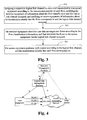
- FIG. 3 is a flowchart illustrating a QoS control method in an embodiment of the invention.
- Figure 4 is a diagram illustrating a QoS control in an embodiment of the invention.
- a logical link channel is assigned by a logical link management function entity between a terminal equipment and an access equipment based on a flow, to prevent a terminal equipment from using a logical link channel illegally, and to control the access equipment and the terminal equipment to perform the QoS control based on the logical link channel.
- the QoS control system in an embodiment of the invention includes mainly a Logical Link Management Function (LLMF) entity 11, a terminal equipment 12, an access equipment 13 and an edge device 14.
- LLMF Logical Link Management Function
- the LLMF 11 is configured to assign a logical link channel for each flow transmitted by a terminal equipment according to a transmission priority corresponding to each flow, notify the terminal equipment 12 of information about the flow classification and the logical link channel assigned, and notify the access equipment 13 of information about the logical link channel assigned and the transmission priority corresponding to the flow.
- the information about the logical link channel may include an identification of the logical link channel.
- the logical link management function entity 11 may include a logical link channel assigning unit 111 and a notifying unit 112.
- the logical link channel assigning unit 111 is configured to assign a logical link channel according to a transmission priority of each flow. Specifically, the logical link channel assigning unit 111 may assign a logical link channel to each flow according to the following rule.
- each logical link channel is represented by an identification of the logical link channel, and the identification of the logical link channel is assigned randomly and discretely at each user side port of the access equipment.
- different identifications of the logical link channel are assigned to different transmission priorities, different identifications or a same identification of the logical link channel is assigned to a same transmission priority.
- the identifications of the logical link channels for the same transmission priority may be the same or different, as long as the identifications for identifying the logical link channels are assigned randomly and discretely.
- the identification of the logical link channel may be an identification of a Virtual Local Area Network (VLAN ID) or an identification of a Permanent Virtual Circuit (PVC ID), or another identification which may distinguish a logical link channel from others, the description of which is omitted here.
- VLAN ID Virtual Local Area Network
- PVC ID Permanent Virtual Circuit
- the notifying unit 112 is configured to notify the terminal equipment of the information about the flow classification and the logical link channel assigned by the logical link channel assigning unit 111, and to notify the access equipment of the information about the transmission priority of each flow and the logical link channel assigned by the logical link channel assigning unit 111.
- the terminal equipment 12 is configured to classify user data messages into each flow according to the flow classification information of the flows.
- the flows are transmitted to the access equipment via the logical link channel assigned.
- the terminal equipment 12 in an embodiment of the invention may include a flow classifying unit 121 and a transmitting unit 122, in order to perform QoS control.
- the flow classifying unit 121 is configured to classify the user data messages into each flow according to the information about flow classification.
- the transmitting unit 122 is configured to transmit each flow classified to the access equipment via the logical link channel assigned.
- the access equipment 13 is configured to perform QoS control according to the logical link channel and the transmission priority that each flow corresponds to.
- the access equipment 13 in an embodiment of the invention includes an identifying unit 131 and a QoS control unit 132.
- the identifying unit 131 is configured to identify the transmission priority that each flow corresponds to according to the identification of the logical link channel.
- the QoS control unit 132 is configured to perform QoS control over the flow transmitted via each logical link channel according to the transmission priority that each logical link channel identified corresponds to.
- the logical link management function (LLMF) entity 11 is further configured to notify the terminal equipment 12 and the access equipment 13 of a parameter for bandwidth QoS control.
- the terminal equipment 12 is further configured to perform a bandwidth control for each flow according to the parameter for bandwidth QoS control after the user data messages have been classified into flows.
- a control unit 123 may be added in the terminal equipment 12 between the flow classifying unit 121 and the transmitting unit 122, and the bandwidth control over each flow is performed by the control unit 123 according to the parameter for bandwidth QoS control.
- the access equipment 13 is further configured to perform QoS control over the flow transmitted via each logical link channel according to the transmission priority and the parameter for bandwidth QoS control that each logical link channel corresponds to. Specifically, the operation may be performed by the QoS control unit 132 in the access equipment 13.
- the parameter for bandwidth QoS control may include the bandwidths for uplink and downlink transmissions.
- the bandwidths assigned for uplink and downlink transmissions from and to the terminal equipment 12 are the bandwidths for uplink and downlink transmissions of the logical link channel of the current flow respectively.
- the bandwidths assigned to uplink and downlink transmissions from and to the access equipment 13 may include the bandwidths for uplink and downlink transmissions of the logical link channel of the current flow, or the bandwidths for uplink and downlink transmissions of the combination of the current flow and the existing flows with the same priority at a single user side port, and/or the bandwidths for uplink and downlink transmissions of the combination of the current flow and the existing flows with the same priority at different user side ports.
- the QoS control unit 132 may further include a user side QoS control unit and/or a network side QoS control unit.
- the user side QoS control unit is configured to perform QoS control at the user side port over the received flow, according to the transmission priority that the logical link channel identified by the identifying unit 131 corresponds to and the bandwidth after the combination of flows received at the port with the same priority, or combine the bandwidths for uplink and downlink transmissions of the logical link channel of the current flows received and the bandwidths for uplink and downlink transmissions of the existing flows with the same priority at the port, perform QoS control at the user side port over the received flows based on the combined bandwidth and the transmission priority, and then transmit the flows after the QoS control to the edge device.
- the network side QoS control unit is configured to perform QoS control at the network side port before the flow is transmitted, according to the transmission priority that the logical link channel at the port corresponds to and the bandwidth after combination of the flows received with the same priority at different user side ports, or combine the bandwidths for uplink and downlink transmissions of data flow with the same transmission priority at different user side ports at the network side port, perform QoS control based on the bandwidths after combination and the different transmission priority to which each combination corresponds, and then transmit the flows to the edge device.
- the QoS control system illustrated in Figure 2 further includes an edge device 14.
- the notifying unit 112 of the logical link management function entity 11 may further be configured to transmit information about the correspondence between the newly assigned identification of the logical link channel and the flow directly or indirectly to the edge device 14.
- the identification of the logical link channel is taken by the edge device 14 as a matching parameter when the flows are classified.
- the edge device 14 further continues the QoS control over the received flow transmitted.
- the logical link management function entity 11 in an embodiment of the invention may be an independent equipment, or may be integrated in other equipments such as the access equipment or the resource management function entity.
- the QoS control process is specifically described here below.
- FIG. 3 it is a flow chart illustrating a QoS control method in an embodiment of the invention. The method includes the following steps.
- Step S11 assigning a respective logical link channel to each flow transmitted by a terminal equipment according to the transmission priority of each flow, notifying the terminal equipment of information about the flow classification and the logical link channel assigned, and notifying an access equipment of information about the transmission priority that the flow corresponds to and the logical link channel assigned.
- the flow identification information includes the source IP address, the destination IP address, the source port, the destination port and the protocol type.
- the logical link channels are assigned to each flow according to the following rule in an embodiment of the invention.
- Each logical link channel is represented with the identification of the logical link channel when the logical link channel is assigned, and the identification of the logical link channel is assigned randomly and discretely at each user side port of the access equipment.
- different identifications of the logical link channel are assigned to different transmission priorities, different identifications or a same identification of the logical link channel is assigned to a same transmission priority.
- the identifications of the logical link channels assigned to flows with the same transmission priorities may be the same or different, as long as the identifications for identifying the logical link channels are assigned randomly and discretely.
- Step S12 The terminal equipment classifies user data messages into flows according to the flow classification information, and then transmits the flows to the access equipment via the logical link channel assigned.
- Step S13 The access equipment performs QoS control according to the logical link channel and the transmission priority that each flow corresponds to.
- the terminal equipment may also be notified of the parameter for bandwidth QoS control in step S11 of an embodiment of the invention.
- the terminal equipment may also perform bandwidth control over each flow according the parameter for bandwidth QoS control, after classifying the user data messages into flows.
- the parameter for bandwidth QoS control may include the bandwidths for uplink and downlink transmissions, and the bandwidths for uplink and downlink transmissions may be bandwidths for uplink and downlink transmissions of the logical link channel of the current flow.
- the access equipment may also be notified of the parameter for bandwidth QoS control.
- the access equipment identifies the transmission priorities to which the flows correspond according to different identifications of the logical link channels, and perform QoS control over the flow transmitted via each logical link channel according to the transmission priorities that each logical link channel correspond to and the parameter for bandwidth QoS control.
- the information about the parameters for the bandwidth control to and from the access equipment may include the bandwidths for uplink and downlink transmissions.
- the bandwidths for uplink and downlink transmissions may include the bandwidth for uplink and downlink transmissions of the logical link channel of the current flow, or the bandwidths for uplink and downlink transmissions after combination of the current flow with the same priority at a single user side port with the existing flows, and/or the bandwidths for uplink and downlink transmissions after combination of the current flow with the same priority at a different user side port with the existing flows.
- the QoS control performed by the access equipment may include a user side QoS control and a network side QoS control, or anyone of the two QoS controls.
- the user side QoS control refers to QoS control at the user side port by the access equipment for the flow just received according to the transmission priority that the logical link channel at the port corresponds to and the bandwidth after combination of the received flows with the same priorities at the port, or combining the bandwidths for uplink and downlink transmissions of the logical link channel of the current flow received and the bandwidths for uplink and down link transmissions of the existing flows at the port, performing QoS control based on the combined bandwidth and the transmission priority.
- the flow after the QoS control has been performed is transmitted, i.e., transmitted to the edge device.
- the network side QoS control refers to performing QoS control at the network side port according to the transmission priority that the logical link channel at the port corresponds to and the combined bandwidth of the received flows with the same priority at different user side ports, or performing QoS control at the network side port based on the combined bandwidth and the different transmission priorities with which each combination associates after the data flows with the same transmission priorities at different user side ports are combined.
- step S 11 information about the correspondence between the identification of the newly assigned logical link channel and the flow may be transmitted to the edge device directly or indirectly in step S 11, and a new step S 14 may be added, in which the edge device takes also the identification of the logical link channel as a matching parameter of a flow classification when performing the flow classification.
- the edge device takes also the identification of the logical link channel as a matching parameter of a flow classification when performing the flow classification.
- FIG. 4 it is a diagram illustrating an embodiment of the QoS control in the invention.
- the terminal equipment is UE and that the access equipment is DSLAM.
- the logical link management function (LLMF) entity an independent equipment is adopted in the embodiment, ant it has the following functions: substituting for the RMF to issue resource control commands to UE, assigning a logical link channel between the UE and the access equipment DSLAM based on flow, to prevent a user from using the logical link channel illegally, and controlling the access equipment DSLAM and UE to realize QoS control based on logical link channel.
- LLMF logical link management function
- the interface between RMF and UE is defined as a U interface
- the interface between LLMF and access equipment DSLAM is defined as an A interface
- the interface between LLMF and RMF is defined as an M interface.
- VLAN ID of an Ethernet IEEE 802.1Q is used to identify the logical link channel in the embodiment. It should be noted that the invention is not limited to that. Any access technology using similar ID to identify a logical link channel, assigning an ID randomly and dynamically, falls in the scope of the invention.
- Step 1 When a request to establish a QoS channel based on flow is received by an RMF and the request is accepted and controlled locally, a resource control command is transmitted to an LLMF entity through an M interface.
- the information carried includes: a user side port ID, a flow ID, flow classification information, QoS parameters for the bandwidths for uplink and downlink transmissions, and transmission priorities etc., in which the flow ID is an identifier for a flow assigned by an RMF entity.
- the flow ID may be used for control, and is not present in the data messages.
- the flow classification information usually means the IP five tuple information, including, a source IP address, a destination IP address, a source port, a destination port and a protocol type.
- Step 2 After the request is received by the LLMF entity, a VLAN ID is assigned to each flow to identify the logical link channel used by the flow, such as VLAN 1, VLAN 2 and VLAN 3 shown in Figure 4 .
- a VLAN ID is assigned in the following way: A VLAN ID is assigned randomly and is meaningful only at a certain user side port, and a VLAN ID may be reused between different user side ports. At a user side port, an assigned VLAND ID with the same priority may be assigned, and also a VLAND ID which is not used may be assigned randomly, but an assigned VLAND ID with different priority cannot be assigned. After a VLAND ID is released, the priority of a flow may be different from that before when the VLAN ID is once again re-assigned to the flow.
- a VLAN ID may also be assigned in other ways, which is not described in detail here.
- a user side port includes N priorities
- the transmission priority of the flow to be assigned is P
- a VLAN may be assigned in the following way:
- the first VLAN ID to be assigned is randomly selected from the VLAN ID space.
- the VLAN ID is put into the set with priority P (It should be noted that once a VLAND ID is assigned, the VLAN ID corresponds to the transmission priority of the related flow, and it is said that the VLAND ID possesses an attribute of the priority). After the step, it may be said that the first assigned VLAND ID possesses the priority of P.
- the subset with the same transmission priority in the set of assigned VLAN ID may be combined with the set of unassigned VLAN ID, to form a set for assignment. It is assumed that the set for assignment includes M samples, and a random number (RAND) is generated at the same time.
- RAND MOD M is a RAND modulo M operation.
- step (e) The VLAND ID assigned in step (d) is assigned as a new VLAN ID, and the VLAN ID is put into the set of priority P. Then the process of assignment ends.
- Step 3 If uplink and downlink flow data with priority of P already exists at the user side port, the LLMF entity combines the existing uplink and downlink flow bandwidth with priority of P at the user side port and the flow bandwidth of the new flow, and calculates the new bandwidths for uplink and downlink transmissions with priority of P at the user side port.
- the LLMF entity may also combine the flows with the same transmission priorities from different user side ports at the network side, and calculate the new bandwidths for uplink and downlink transmissions with the priority of P from different user side ports at the network side.
- Step 4 The LLMF entity transmits the information obtained in step 2 and 3 via the U interface down to UE, and via the A interface down to the access equipment, respectively.
- the information transmitted includes: the flow classification information, the bandwidths for uplink and downlink transmissions of the logical link channel of the current flow, the newly assigned VLAN ID.
- the information about the transmission priorities are not necessary to be transmitted to UE.
- the UE classifies user data messages into different flows according the flow classification information and the corresponding VLAN ID, and a VLAN ID is assigned to the assigned flow.
- the UE may perform a bandwidth QoS control for each flow according to the bandwidths for uplink and downlink transmissions.
- the information transmitted may include: the port ID at the user side and the newly assigned VLAN ID, the bandwidths for uplink and downlink transmissions with the priority that the newly calculated VLAN ID corresponds to, information about the transmission priorities. It may further include: ID of the port at the network side of the access equipment, the transmission priority of the port at the network side, the newly calculated combined bandwidths for uplink and downlink corresponding to the priority.
- the access equipment performs QoS control over ports at the user side, based on different transmission priorities, according to the IDs of the ports at the user side, the VLAN ID, the transmission priorities, and the bandwidths for uplink and downlink transmissions at the user side port. Furthermore, the access equipment performs QoS control over ports at the network side, based on the combined flows with different transmission priorities, according the IDs of the ports at the network side, the transmission priorities of ports at the network side and the bandwidths for uplink and downlink transmissions with the respective transmission priority.
- Step 5 the LLMF entity returns information about the correspondence between the newly assigned VLAN ID and the flow ID to the RMF entity, and the RMF entity commands the edge device to use the VLAN ID information as a matching parameter when the flows are classified.
- the VLAN ID is checked and handled by the edge device.
- Step 3 the combination of flows and the calculation of the bandwidths for uplink and downlink transmissions based on the combined flows may not be performed. Instead, the bandwidths for uplink and downlink transmissions of the current flow may be transmitted directly to the access equipment.
- the access equipment combines the flows with a same priority at a port at the user side, and then performs QoS control based on the transmission priorities and the bandwidths for uplink and downlink transmissions; At a port at the network side, the access equipment combines the flows with a same priority from different user side ports, and then performs QoS control based on the transmission priorities and the bandwidth for uplink and downlink transmissions.
Abstract
Claims (17)
- Procédé de contrôle de la Qualité de Service, QoS, caractérisé en ce qu'il comprend :(a) l'assignation, par une entité fonctionnelle de gestion de liaison logique (11), d'un canal de liaison logique à chaque flux transmis par un équipement terminal (12) en fonction de la priorité de transmission de chaque flux, la notification à l'équipement terminal (12) d'informations sur le classement des flux et d'informations sur le canal de liaison logique assigné, et la notification à un équipement d'accès (13) d'informations sur le canal de liaison logique assigné et sur la priorité de transmission,(b) le classement, par l'équipement terminal (12), de messages de données utilisateur en flux en fonction des informations sur le classement des flux et la transmission de messages de données utilisateur à l'équipement d'accès (13) par l'intermédiaire du canal de liaison logique, et(c) l'exécution du contrôle de la qualité de service, QoS, par l'équipement d'accès (13), en fonction du canal de liaison logique auquel correspond chaque flux, ainsi que de la priorité de transmission à laquelle correspond chaque flux.
- Procédé de contrôle de la qualité de service, QoS, selon la revendication 1, caractérisé en ce que l'étape (a) comprend en outre :la notification à l'équipement terminal (12) d'informations au sujet d'un paramètre pour le contrôle de la qualité de service, QoS, en bande passante de chaque flux, etl'étape (b) comprend en outre :l'exécution d'un contrôle de la qualité de service, QoS, en bande passante sur chaque flux en fonction du paramètre pour le contrôle de la qualité de service, QoS, en bande passante de chaque flux, après le classement en flux des messages de données utilisateur par l'équipement terminal (12) et avant la transmission de messages de données utilisateur à l'équipement d'accès (13).
- Procédé de contrôle de la qualité de service, QoS, selon la revendication 1, caractérisé en ce que l'étape (a) comprend en outre :la notification à l'équipement d'accès (13) d'un paramètre pour le contrôle de la qualité de service, QoS, en bande passante, et l'étape (c) comprend :(c1) l'identification des priorités de transmission des flux en fonction des identifications de canaux de liaisons logiques différents,(c2) l'exécution d'un contrôle de la qualité de service, QoS, sur les flux transmis par l'intermédiaire de chaque canal de liaison logique en fonction de la priorité de transmission du canal de liaison logique et du paramètre acquis pour le contrôle de la qualité de service, QoS, en bande passante.
- Procédé de contrôle de la qualité de service, QoS, selon l'une quelconque des revendications 1 à 3, caractérisé en ce que l'assignation d'un canal de liaison logique à chaque flux dans l'étape (a) comprend :l'assignation aléatoire et distincte d'un canal de liaison logique à chaque port du côté utilisateur de l'équipement d'accès (13), et pendant ce temps, l'assignation de canaux de liaisons logiques différents à différentes priorités de transmission ainsi que l'assignation de canaux de liaisons logiques différents ou du même canal de liaison logique à la même priorité de transmission.
- Procédé de contrôle de la qualité de service, QoS, selon la revendication 4, caractérisé en ce que le canal de liaison logique assigné est identifié grâce à une identification du canal de liaison logique.
- Procédé de contrôle de la qualité de service, QoS, selon la revendication 5, caractérisé en ce que l'identification du canal de liaison logique comprend l'identification d'un réseau local virtuel (VLAN ID) ou l'identification d'un circuit virtuel permanent (PVC ID).
- Procédé de contrôle de la qualité de service, QoS, selon la revendication 3, caractérisé en ce que l'exécution du contrôle de la qualité de service, QoS, par l'équipement d'accès (13) à l'étape (c2) comprend :après la réception des flux, l'exécution par l'équipement d'accès (13) d'un contrôle de la qualité de service, QoS, pour les flux reçus au niveau d'un port du côté utilisateur en fonction de la priorité de transmission du canal de liaison logique au niveau du port et du paramètre de contrôle de la qualité de service, QoS, en bande passante,et/ouavant la transmission de chaque flux, l'exécution par l'équipement d'accès (13) d'un contrôle de la qualité de service, QoS, au niveau d'un port du côté réseau en fonction du paramètre de contrôle de la qualité de service, QoS, en bande passante et des priorités de transmission, après qu'un certain nombre de canaux logiques présentant la même priorité de transmission, provenant de différents ports du côté utilisateur,sont combinés au niveau du port du côté réseau.
- Procédé de contrôle de la qualité de service, QoS, selon l'une quelconque des revendications 1 à 3, caractérisé en ce que l'équipement terminal (12) comprend un équipement utilisateur ou un équipement d'accès à distance (13).
- Entité fonctionnelle de gestion de liaison logique (11), caractérisée en ce qu'elle comprend :une unité d'assignation de canal de liaison logique (111), configurée pour assigner un canal de liaison logique en fonction de la priorité de transmission de chaque flux, etune unité de notification (112), configurée pour notifier à un équipement terminal (12) des informations sur un classement des flux et des informations sur le canal de liaison logique assigné par l'unité d'assignation de canal de liaison logique (111) pour chaque flux, et pour notifier à un équipement d'accès (13) des informations sur le canal de liaison logique assigné par l'unité d'assignation de canal de liaison logique (111) et sur la priorité de transmission correspondant à chaque flux.
- Entité fonctionnelle de gestion de liaison logique (11) selon la revendication 9, caractérisée en ce que l'unité d'assignation de canal de liaison logique (111) est configurée pour assigner en même temps des canaux de liaisons logiques différents à différentes priorités de transmission au niveau de chaque port du côté utilisateur de l'équipement d'accès (13), et pour assigner des canaux de liaisons logiques différents ou un même canal de liaison logique pour une même priorité de transmission, et le canal de liaison logique est assigné aléatoirement et de manière distincte.
- Système de contrôle de la qualité de service, QoS, caractérisé en ce que le système comprend
l'entité fonctionnelle de gestion de liaison logique (11) selon la revendication 9 ou 10, un équipement terminal (12) configuré pour classer des messages de données utilisateur dans chaque flux en fonction des informations sur le classement des flux, et pour transmettre les flux à l'équipement d'accès (13) par l'intermédiaire du canal de liaison logique, et
un équipement d'accès (13) configuré pour effectuer un contrôle de la qualité de service, QoS, en fonction du canal de liaison logique et de la priorité de transmission correspondant à chaque flux. - Système de contrôle de la qualité de service, QoS, selon la revendication 11, caractérisé en ce que l'équipement terminal (12) comprend :une unité de classement en flux (121) configurée pour classer les messages de données utilisateur dans chaque flux en fonction des informations de classement des flux, etune unité de transmission (122) configurée pour transmettre chaque flux à l'équipement d'accès (13) par l'intermédiaire du canal de liaison logique respectivement assigné.
- Système de contrôle de la qualité de service, QoS, selon la revendication 11, caractérisé en ce que l'équipement d'accès (13) comprend :une unité d'identification (131) configurée pour identifier la priorité de transmission correspondant à chaque flux en fonction de l'identification du canal de liaison logique assigné à chaque flux, etune unité de contrôle de la qualité de service, QoS, (132) configurée pour effectuer un contrôle de la qualité de service, QoS, sur les flux transmis par l'intermédiaire de chaque canal de liaison logique en fonction de la priorité de transmission correspondant à chaque canal de liaison logique.
- Système de contrôle de la qualité de service, QoS, selon la revendication 11, caractérisé en ce qu'il comprend :l'entité fonctionnelle de gestion de liaison logique qui est en outre configurée pour transmettre un paramètre pour le contrôle de la qualité de service, QoS, en bande passante à l'équipement terminal (12) et à l'équipement d'accès (13),l'équipement terminal (12) qui est en outre configuré pour effectuer un contrôle de bande passante sur chaque flux en fonction du paramètre de contrôle de la qualité de service, QoS, en bande passante, etl'équipement d'accès (13) qui est en outre configuré pour effectuer un contrôle de la qualité de service, QoS, sur les flux transmis par l'intermédiaire de chaque canal de liaison logique en fonction du paramètre de contrôle de la qualité de service, QoS, en bande passante correspondant au canal de liaison logique.
- Système de contrôle de la qualité de service, QoS, selon la revendication 13, caractérisé en ce que l'unité de contrôle de la qualité de service, QoS, (132) comprend :une unité de contrôle de la qualité de service, QoS, du côté utilisateur, configurée pour effectuer un contrôle de la qualité de service, QoS, sur les flux reçus au niveau d'un port du côté utilisateur, en fonction de la priorité de transmission à laquelle correspond le canal de liaison logique au niveau du port et du paramètre de contrôle de la qualité de service, QoS, en bande passante, et/ouune unité de contrôle de la qualité de service, QoS, du côté réseau, configurée pour effectuer un contrôle de la qualité de service, QoS, au niveau d'un port du côté réseau en fonction des paramètres de contrôle de la qualité de service, QoS, en bande passante et des priorités de transmission de flux après que les flux présentant la même priorité de transmission provenant de différents ports du côté utilisateur sont combinés au niveau du port du côté réseau, et avant que chaque flux soit transmis.
- Système de contrôle de la qualité de service, QoS, selon l'une quelconque des revendications 12 à 15, caractérisé en ce que l'entité fonctionnelle de gestion de liaison logique est un équipement indépendant ou intégré dans l'équipement d'accès (13), ou encore intégré dans une entité fonctionnelle de gestion de ressources.
- Système de contrôle de la qualité de service, QoS, selon l'une quelconque des revendications 12 à 15, caractérisé en ce que l'équipement terminal (12) comprend un équipement utilisateur ou un équipement d'accès à distance (13).
Priority Applications (1)
| Application Number | Priority Date | Filing Date | Title |
|---|---|---|---|
| EP12167249.7A EP2487847B1 (fr) | 2006-01-26 | 2006-10-23 | Procédé et système de contrôle de la QOS |
Applications Claiming Priority (2)
| Application Number | Priority Date | Filing Date | Title |
|---|---|---|---|
| CN2006100334510A CN101009637B (zh) | 2006-01-26 | 2006-01-26 | 服务质量控制方法、系统及逻辑链路管理功能设备 |
| PCT/CN2006/002825 WO2007085159A1 (fr) | 2006-01-26 | 2006-10-23 | Procédé et système de contrôle de la qos |
Related Child Applications (3)
| Application Number | Title | Priority Date | Filing Date |
|---|---|---|---|
| EP12167249.7A Division EP2487847B1 (fr) | 2006-01-26 | 2006-10-23 | Procédé et système de contrôle de la QOS |
| EP12167249.7A Division-Into EP2487847B1 (fr) | 2006-01-26 | 2006-10-23 | Procédé et système de contrôle de la QOS |
| EP12167249.7 Division-Into | 2012-05-09 |
Publications (4)
| Publication Number | Publication Date |
|---|---|
| EP1978682A1 EP1978682A1 (fr) | 2008-10-08 |
| EP1978682A4 EP1978682A4 (fr) | 2010-03-10 |
| EP1978682B1 true EP1978682B1 (fr) | 2012-07-18 |
| EP1978682B9 EP1978682B9 (fr) | 2012-09-26 |
Family
ID=38308849
Family Applications (2)
| Application Number | Title | Priority Date | Filing Date |
|---|---|---|---|
| EP12167249.7A Active EP2487847B1 (fr) | 2006-01-26 | 2006-10-23 | Procédé et système de contrôle de la QOS |
| EP06817791A Active EP1978682B9 (fr) | 2006-01-26 | 2006-10-23 | Procédé et système de contrôle de la qos |
Family Applications Before (1)
| Application Number | Title | Priority Date | Filing Date |
|---|---|---|---|
| EP12167249.7A Active EP2487847B1 (fr) | 2006-01-26 | 2006-10-23 | Procédé et système de contrôle de la QOS |
Country Status (5)
| Country | Link |
|---|---|
| EP (2) | EP2487847B1 (fr) |
| CN (1) | CN101009637B (fr) |
| ES (2) | ES2515721T3 (fr) |
| PT (1) | PT2487847E (fr) |
| WO (1) | WO2007085159A1 (fr) |
Families Citing this family (5)
| Publication number | Priority date | Publication date | Assignee | Title |
|---|---|---|---|---|
| CN101729398A (zh) * | 2009-02-19 | 2010-06-09 | 中兴通讯股份有限公司 | QoS优先级信息的发送方法、PD-FE、TRC-FE |
| EP2586162B1 (fr) * | 2010-06-25 | 2015-01-14 | Siemens Aktiengesellschaft | Transmission prioritaire de télégrammes de données |
| CN102572968B (zh) * | 2010-12-17 | 2016-08-03 | 北京中水科水电科技开发有限公司 | 一种多信道切换的方法及装置 |
| CN106850460B (zh) * | 2017-02-10 | 2020-05-19 | 北京邮电大学 | 一种业务流聚合方法及装置 |
| CN112688849B (zh) * | 2020-12-25 | 2022-06-24 | 京信网络系统股份有限公司 | 基于流分类的QinQ配置方法、装置、介质和通信设备 |
Family Cites Families (6)
| Publication number | Priority date | Publication date | Assignee | Title |
|---|---|---|---|---|
| USH2051H1 (en) * | 2000-09-29 | 2002-11-05 | Opuswave Networks, Inc. | System and method for providing multiple quality of service classes |
| US20020188732A1 (en) * | 2001-06-06 | 2002-12-12 | Buckman Charles R. | System and method for allocating bandwidth across a network |
| JP2003110574A (ja) * | 2001-09-27 | 2003-04-11 | Matsushita Electric Ind Co Ltd | 無線通信システム、それに用いるパケット伝送装置及びアクセスポイント |
| AU2002237171A1 (en) * | 2002-02-22 | 2003-09-09 | Linkair Communications, Inc. | A method of priority control in wireless packet data communications |
| US6885638B2 (en) * | 2002-06-13 | 2005-04-26 | Motorola, Inc. | Method and apparatus for enhancing the quality of service of a wireless communication |
| CA2393373A1 (fr) * | 2002-07-15 | 2004-01-15 | Anthony Gerkis | Appareil, systeme et methode de transmission de donnees offrant differents attributs de qualite de service |
-
2006
- 2006-01-26 CN CN2006100334510A patent/CN101009637B/zh active Active
- 2006-10-23 EP EP12167249.7A patent/EP2487847B1/fr active Active
- 2006-10-23 PT PT121672497T patent/PT2487847E/pt unknown
- 2006-10-23 ES ES12167249.7T patent/ES2515721T3/es active Active
- 2006-10-23 ES ES06817791T patent/ES2389379T3/es active Active
- 2006-10-23 WO PCT/CN2006/002825 patent/WO2007085159A1/fr active Application Filing
- 2006-10-23 EP EP06817791A patent/EP1978682B9/fr active Active
Also Published As
| Publication number | Publication date |
|---|---|
| ES2515721T3 (es) | 2014-10-30 |
| ES2389379T3 (es) | 2012-10-25 |
| CN101009637B (zh) | 2011-09-21 |
| EP1978682A4 (fr) | 2010-03-10 |
| EP2487847B1 (fr) | 2014-08-13 |
| WO2007085159A1 (fr) | 2007-08-02 |
| CN101009637A (zh) | 2007-08-01 |
| EP1978682A1 (fr) | 2008-10-08 |
| EP2487847A1 (fr) | 2012-08-15 |
| PT2487847E (pt) | 2014-10-16 |
| EP1978682B9 (fr) | 2012-09-26 |
Similar Documents
| Publication | Publication Date | Title |
|---|---|---|
| US6714515B1 (en) | Policy server and architecture providing radio network resource allocation rules | |
| US6631122B1 (en) | Method and system for wireless QOS agent for all-IP network | |
| JP5793280B2 (ja) | 無線通信システムにおける資源スケジューリング方法及び基地局 | |
| KR100822707B1 (ko) | 통합망 시스템에서의 서비스 품질 관리 장치 및 그 방법 | |
| EP2629554B1 (fr) | Procédé et système de contrôle de service, enodeb et passerelle de réseau de données en mode paquet | |
| KR100699531B1 (ko) | 휴대 인터넷 서비스의 큐오에스 제공 장치 및 방법 | |
| JP2005502275A (ja) | Ip通信網における方法及び装置 | |
| WO2020155940A1 (fr) | Procédé et appareil de communication | |
| GB2341059A (en) | Internet protocol flow detection | |
| US11582143B2 (en) | Techniques for policy management of multi-connectivity network protocols | |
| WO2007035792A1 (fr) | Indication de mouvement a une partie effectuant une requete de ressources | |
| US20210352630A1 (en) | Base station, system, and method | |
| EP1978699A1 (fr) | Procédé et système de commande de flux dynamique | |
| EP2214359B1 (fr) | Procédé et système de commande de politique pour dispositif de couche deux | |
| EP1978682B1 (fr) | Procédé et système de contrôle de la qos | |
| CN110351890B (zh) | 集中式单元-分布式单元架构下的通信方法、通信设备 | |
| EP1983695B9 (fr) | Procédé, appareil et système de régulation de trafic ascendant dans un réseau d'accès | |
| CN113645666A (zh) | 流量控制方法、网络设备与通信系统 | |
| CN112099871B (zh) | 一种服务质量配置方法及装置 | |
| EP1933500B2 (fr) | Systeme et procede de commande de ressource du reseau d'acces | |
| JP5335712B2 (ja) | QoS制御装置、及びQoS制御方法 | |
| Li et al. | Analysis and Modeling of the QoS Mechanism in ATN | |
| CN117643038A (zh) | 用于在电信系统中在ue路由选择策略(ursp)中引用本地资源的方法及其系统 | |
| Zivkovic et al. | QoS attributes for packet switched services in 3rd generation mobile systems (UMTS) | |
| JP2014230036A (ja) | 複数の無線ベアラにアクセスする方法及び装置 |
Legal Events
| Date | Code | Title | Description |
|---|---|---|---|
| PUAI | Public reference made under article 153(3) epc to a published international application that has entered the european phase |
Free format text: ORIGINAL CODE: 0009012 |
|
| 17P | Request for examination filed |
Effective date: 20080730 |
|
| AK | Designated contracting states |
Kind code of ref document: A1 Designated state(s): AT BE BG CH CY CZ DE DK EE ES FI FR GB GR HU IE IS IT LI LT LU LV MC NL PL PT RO SE SI SK TR |
|
| A4 | Supplementary search report drawn up and despatched |
Effective date: 20100205 |
|
| GRAP | Despatch of communication of intention to grant a patent |
Free format text: ORIGINAL CODE: EPIDOSNIGR1 |
|
| DAX | Request for extension of the european patent (deleted) | ||
| GRAS | Grant fee paid |
Free format text: ORIGINAL CODE: EPIDOSNIGR3 |
|
| GRAA | (expected) grant |
Free format text: ORIGINAL CODE: 0009210 |
|
| AK | Designated contracting states |
Kind code of ref document: B1 Designated state(s): AT BE BG CH CY CZ DE DK EE ES FI FR GB GR HU IE IS IT LI LT LU LV MC NL PL PT RO SE SI SK TR |
|
| REG | Reference to a national code |
Ref country code: GB Ref legal event code: FG4D |
|
| REG | Reference to a national code |
Ref country code: CH Ref legal event code: EP |
|
| REG | Reference to a national code |
Ref country code: IE Ref legal event code: FG4D Ref country code: AT Ref legal event code: REF Ref document number: 567264 Country of ref document: AT Kind code of ref document: T Effective date: 20120815 |
|
| REG | Reference to a national code |
Ref country code: DE Ref legal event code: R096 Ref document number: 602006030886 Country of ref document: DE Effective date: 20120913 |
|
| REG | Reference to a national code |
Ref country code: NL Ref legal event code: T3 |
|
| REG | Reference to a national code |
Ref country code: SE Ref legal event code: TRGR |
|
| REG | Reference to a national code |
Ref country code: ES Ref legal event code: FG2A Ref document number: 2389379 Country of ref document: ES Kind code of ref document: T3 Effective date: 20121025 |
|
| REG | Reference to a national code |
Ref country code: AT Ref legal event code: MK05 Ref document number: 567264 Country of ref document: AT Kind code of ref document: T Effective date: 20120718 |
|
| REG | Reference to a national code |
Ref country code: LT Ref legal event code: MG4D Effective date: 20120718 |
|
| PG25 | Lapsed in a contracting state [announced via postgrant information from national office to epo] |
Ref country code: BE Free format text: LAPSE BECAUSE OF FAILURE TO SUBMIT A TRANSLATION OF THE DESCRIPTION OR TO PAY THE FEE WITHIN THE PRESCRIBED TIME-LIMIT Effective date: 20120718 Ref country code: FI Free format text: LAPSE BECAUSE OF FAILURE TO SUBMIT A TRANSLATION OF THE DESCRIPTION OR TO PAY THE FEE WITHIN THE PRESCRIBED TIME-LIMIT Effective date: 20120718 Ref country code: AT Free format text: LAPSE BECAUSE OF FAILURE TO SUBMIT A TRANSLATION OF THE DESCRIPTION OR TO PAY THE FEE WITHIN THE PRESCRIBED TIME-LIMIT Effective date: 20120718 Ref country code: IS Free format text: LAPSE BECAUSE OF FAILURE TO SUBMIT A TRANSLATION OF THE DESCRIPTION OR TO PAY THE FEE WITHIN THE PRESCRIBED TIME-LIMIT Effective date: 20121118 Ref country code: CY Free format text: LAPSE BECAUSE OF FAILURE TO SUBMIT A TRANSLATION OF THE DESCRIPTION OR TO PAY THE FEE WITHIN THE PRESCRIBED TIME-LIMIT Effective date: 20120718 Ref country code: LT Free format text: LAPSE BECAUSE OF FAILURE TO SUBMIT A TRANSLATION OF THE DESCRIPTION OR TO PAY THE FEE WITHIN THE PRESCRIBED TIME-LIMIT Effective date: 20120718 |
|
| PG25 | Lapsed in a contracting state [announced via postgrant information from national office to epo] |
Ref country code: PT Free format text: LAPSE BECAUSE OF FAILURE TO SUBMIT A TRANSLATION OF THE DESCRIPTION OR TO PAY THE FEE WITHIN THE PRESCRIBED TIME-LIMIT Effective date: 20121119 Ref country code: GR Free format text: LAPSE BECAUSE OF FAILURE TO SUBMIT A TRANSLATION OF THE DESCRIPTION OR TO PAY THE FEE WITHIN THE PRESCRIBED TIME-LIMIT Effective date: 20121019 Ref country code: PL Free format text: LAPSE BECAUSE OF FAILURE TO SUBMIT A TRANSLATION OF THE DESCRIPTION OR TO PAY THE FEE WITHIN THE PRESCRIBED TIME-LIMIT Effective date: 20120718 Ref country code: SI Free format text: LAPSE BECAUSE OF FAILURE TO SUBMIT A TRANSLATION OF THE DESCRIPTION OR TO PAY THE FEE WITHIN THE PRESCRIBED TIME-LIMIT Effective date: 20120718 Ref country code: LV Free format text: LAPSE BECAUSE OF FAILURE TO SUBMIT A TRANSLATION OF THE DESCRIPTION OR TO PAY THE FEE WITHIN THE PRESCRIBED TIME-LIMIT Effective date: 20120718 |
|
| PG25 | Lapsed in a contracting state [announced via postgrant information from national office to epo] |
Ref country code: RO Free format text: LAPSE BECAUSE OF FAILURE TO SUBMIT A TRANSLATION OF THE DESCRIPTION OR TO PAY THE FEE WITHIN THE PRESCRIBED TIME-LIMIT Effective date: 20120718 Ref country code: EE Free format text: LAPSE BECAUSE OF FAILURE TO SUBMIT A TRANSLATION OF THE DESCRIPTION OR TO PAY THE FEE WITHIN THE PRESCRIBED TIME-LIMIT Effective date: 20120718 Ref country code: DK Free format text: LAPSE BECAUSE OF FAILURE TO SUBMIT A TRANSLATION OF THE DESCRIPTION OR TO PAY THE FEE WITHIN THE PRESCRIBED TIME-LIMIT Effective date: 20120718 Ref country code: CZ Free format text: LAPSE BECAUSE OF FAILURE TO SUBMIT A TRANSLATION OF THE DESCRIPTION OR TO PAY THE FEE WITHIN THE PRESCRIBED TIME-LIMIT Effective date: 20120718 |
|
| PLBE | No opposition filed within time limit |
Free format text: ORIGINAL CODE: 0009261 |
|
| STAA | Information on the status of an ep patent application or granted ep patent |
Free format text: STATUS: NO OPPOSITION FILED WITHIN TIME LIMIT |
|
| PG25 | Lapsed in a contracting state [announced via postgrant information from national office to epo] |
Ref country code: MC Free format text: LAPSE BECAUSE OF NON-PAYMENT OF DUE FEES Effective date: 20121031 Ref country code: SK Free format text: LAPSE BECAUSE OF FAILURE TO SUBMIT A TRANSLATION OF THE DESCRIPTION OR TO PAY THE FEE WITHIN THE PRESCRIBED TIME-LIMIT Effective date: 20120718 |
|
| REG | Reference to a national code |
Ref country code: CH Ref legal event code: PL |
|
| 26N | No opposition filed |
Effective date: 20130419 |
|
| REG | Reference to a national code |
Ref country code: IE Ref legal event code: MM4A |
|
| PG25 | Lapsed in a contracting state [announced via postgrant information from national office to epo] |
Ref country code: BG Free format text: LAPSE BECAUSE OF FAILURE TO SUBMIT A TRANSLATION OF THE DESCRIPTION OR TO PAY THE FEE WITHIN THE PRESCRIBED TIME-LIMIT Effective date: 20121018 Ref country code: IE Free format text: LAPSE BECAUSE OF NON-PAYMENT OF DUE FEES Effective date: 20121023 Ref country code: LI Free format text: LAPSE BECAUSE OF NON-PAYMENT OF DUE FEES Effective date: 20121031 Ref country code: CH Free format text: LAPSE BECAUSE OF NON-PAYMENT OF DUE FEES Effective date: 20121031 |
|
| REG | Reference to a national code |
Ref country code: DE Ref legal event code: R097 Ref document number: 602006030886 Country of ref document: DE Effective date: 20130419 |
|
| PG25 | Lapsed in a contracting state [announced via postgrant information from national office to epo] |
Ref country code: TR Free format text: LAPSE BECAUSE OF FAILURE TO SUBMIT A TRANSLATION OF THE DESCRIPTION OR TO PAY THE FEE WITHIN THE PRESCRIBED TIME-LIMIT Effective date: 20120718 |
|
| PG25 | Lapsed in a contracting state [announced via postgrant information from national office to epo] |
Ref country code: LU Free format text: LAPSE BECAUSE OF NON-PAYMENT OF DUE FEES Effective date: 20121023 |
|
| PG25 | Lapsed in a contracting state [announced via postgrant information from national office to epo] |
Ref country code: HU Free format text: LAPSE BECAUSE OF FAILURE TO SUBMIT A TRANSLATION OF THE DESCRIPTION OR TO PAY THE FEE WITHIN THE PRESCRIBED TIME-LIMIT Effective date: 20061023 |
|
| REG | Reference to a national code |
Ref country code: FR Ref legal event code: PLFP Year of fee payment: 11 |
|
| REG | Reference to a national code |
Ref country code: FR Ref legal event code: PLFP Year of fee payment: 12 |
|
| REG | Reference to a national code |
Ref country code: FR Ref legal event code: PLFP Year of fee payment: 13 |
|
| PGFP | Annual fee paid to national office [announced via postgrant information from national office to epo] |
Ref country code: NL Payment date: 20230915 Year of fee payment: 18 Ref country code: IT Payment date: 20230913 Year of fee payment: 18 Ref country code: GB Payment date: 20230831 Year of fee payment: 18 |
|
| PGFP | Annual fee paid to national office [announced via postgrant information from national office to epo] |
Ref country code: SE Payment date: 20230912 Year of fee payment: 18 Ref country code: FR Payment date: 20230911 Year of fee payment: 18 |
|
| PGFP | Annual fee paid to national office [announced via postgrant information from national office to epo] |
Ref country code: ES Payment date: 20231108 Year of fee payment: 18 |
|
| PGFP | Annual fee paid to national office [announced via postgrant information from national office to epo] |
Ref country code: DE Payment date: 20230830 Year of fee payment: 18 |