EP1978643A1 - Paritätserzeugungsschaltung, zähler und zählverfahren - Google Patents
Paritätserzeugungsschaltung, zähler und zählverfahren Download PDFInfo
- Publication number
- EP1978643A1 EP1978643A1 EP06711995A EP06711995A EP1978643A1 EP 1978643 A1 EP1978643 A1 EP 1978643A1 EP 06711995 A EP06711995 A EP 06711995A EP 06711995 A EP06711995 A EP 06711995A EP 1978643 A1 EP1978643 A1 EP 1978643A1
- Authority
- EP
- European Patent Office
- Prior art keywords
- parity
- bit
- data
- base
- bits
- Prior art date
- Legal status (The legal status is an assumption and is not a legal conclusion. Google has not performed a legal analysis and makes no representation as to the accuracy of the status listed.)
- Withdrawn
Links
Images





Classifications
-
- H—ELECTRICITY
- H03—ELECTRONIC CIRCUITRY
- H03M—CODING; DECODING; CODE CONVERSION IN GENERAL
- H03M13/00—Coding, decoding or code conversion, for error detection or error correction; Coding theory basic assumptions; Coding bounds; Error probability evaluation methods; Channel models; Simulation or testing of codes
- H03M13/03—Error detection or forward error correction by redundancy in data representation, i.e. code words containing more digits than the source words
- H03M13/05—Error detection or forward error correction by redundancy in data representation, i.e. code words containing more digits than the source words using block codes, i.e. a predetermined number of check bits joined to a predetermined number of information bits
- H03M13/11—Error detection or forward error correction by redundancy in data representation, i.e. code words containing more digits than the source words using block codes, i.e. a predetermined number of check bits joined to a predetermined number of information bits using multiple parity bits
-
- G—PHYSICS
- G06—COMPUTING OR CALCULATING; COUNTING
- G06F—ELECTRIC DIGITAL DATA PROCESSING
- G06F11/00—Error detection; Error correction; Monitoring
- G06F11/07—Responding to the occurrence of a fault, e.g. fault tolerance
- G06F11/08—Error detection or correction by redundancy in data representation, e.g. by using checking codes
- G06F11/10—Adding special bits or symbols to the coded information, e.g. parity check, casting out 9's or 11's
-
- G—PHYSICS
- G06—COMPUTING OR CALCULATING; COUNTING
- G06F—ELECTRIC DIGITAL DATA PROCESSING
- G06F7/00—Methods or arrangements for processing data by operating upon the order or content of the data handled
- G06F7/60—Methods or arrangements for performing computations using a digital non-denominational number representation, i.e. number representation without radix; Computing devices using combinations of denominational and non-denominational quantity representations, e.g. using difunction pulse trains, STEELE computers, phase computers
- G06F7/607—Methods or arrangements for performing computations using a digital non-denominational number representation, i.e. number representation without radix; Computing devices using combinations of denominational and non-denominational quantity representations, e.g. using difunction pulse trains, STEELE computers, phase computers number-of-ones counters, i.e. devices for counting the number of input lines set to ONE among a plurality of input lines, also called bit counters or parallel counters
-
- H—ELECTRICITY
- H03—ELECTRONIC CIRCUITRY
- H03M—CODING; DECODING; CODE CONVERSION IN GENERAL
- H03M13/00—Coding, decoding or code conversion, for error detection or error correction; Coding theory basic assumptions; Coding bounds; Error probability evaluation methods; Channel models; Simulation or testing of codes
- H03M13/03—Error detection or forward error correction by redundancy in data representation, i.e. code words containing more digits than the source words
- H03M13/05—Error detection or forward error correction by redundancy in data representation, i.e. code words containing more digits than the source words using block codes, i.e. a predetermined number of check bits joined to a predetermined number of information bits
- H03M13/09—Error detection only, e.g. using cyclic redundancy check [CRC] codes or single parity bit
-
- H—ELECTRICITY
- H03—ELECTRONIC CIRCUITRY
- H03M—CODING; DECODING; CODE CONVERSION IN GENERAL
- H03M13/00—Coding, decoding or code conversion, for error detection or error correction; Coding theory basic assumptions; Coding bounds; Error probability evaluation methods; Channel models; Simulation or testing of codes
- H03M13/65—Purpose and implementation aspects
- H03M13/6575—Implementations based on combinatorial logic, e.g. Boolean circuits
Definitions
- the present invention relates to a parity generation circuit, a counter circuit, and a counting method for counting the number of '1's contained in binary data.
- the invention relates to a parity generation circuit, a counter circuit, and a counting method capable of obtaining a parity of a result of population count at high speed without affecting population count operation.
- a population count refers to counting the number of '1's in binary data, and some CPUs (Central Processing Units) is configured to issue a POPC (POPulation Count) instruction to perform the counting.
- CPUs Central Processing Units
- POPC POPulation Count
- Patent Document 1 discloses a conventional technology to realize a circuit that executes the POPC instruction.
- Patent Document 1 Japanese Patent Application Laid-open No. 2005-165793
- a CPU that ensures the validity of data using a parity added to operation input/output data.
- a CPU executes a POPC instruction by hardware, how to obtain the parity of the operation result of the POPC instruction becomes an issue.
- the instruction processing time is prolonged by the time taken to calculate the parity. This reduces the effect of implementing the POPC instruction by hardware to process the instruction at high speed. Therefore, to avoid affecting the cycle time required for the operation, the parity needs to be calculated in the cycle time equal to or less than that of the operation. To accomplish this, the parity of the result of the POPC instruction needs to be predicted from input data.
- the parity needs to be predicted by a separate circuit in parallel with the population count. This parity prediction is required to predict the parity of the operation result from the input data of the POPC instruction and its parity.
- the present invention has been achieved to solve the above problems in the conventional technology and it is an object of the present invention to provide a parity generation circuit, a counter circuit, and a counting method capable of obtaining a parity of a result of population count at high speed without affecting population count operation.
- a parity generation circuit that receives data and a parity of the data, and outputs a parity of count information on a specific item of the data represented as a base-n number (n is a natural number equal to or larger than 2), includes a determining unit that determines that number of specific items of the data represented as a base-n number is a specific value; and an inverting unit that outputs, as the parity of the count information, any one of a value of the parity of the data and an inverted value of the parity depending on a result of determination by the determining unit.
- the determining unit decodes that the number of specific items of eight-bit data represented as a base-n number is any one of 0, 1, 6, and 7.
- the determining unit determines whether the number of specific items of eight-bit data represented as a base-n number is any one of 0, 1, 6, and 7 based on a combination of the number of specific items in upper four bits and the number of specific items in lower four bits of the eight-bit data represented as a base-n number.
- a counter circuit that receives data and a parity of the data, and outputs count information on 1 in the data represented as a base-n number (n is a natural number equal to or larger than 2) and a parity of the count information, includes a determining unit that determines that number of specific items of the data represented as a base-n number is a specific value; and an inverting unit that outputs, as the parity of the count information, any one of a value of the parity of the data and an inverted value of the parity depending on a result of determination by the determining unit.
- the determining unit decodes that the number of specific items of eight-bit data represented as a base-n number is any one of 0, 1, 6, and 7.
- the determining unit determines whether the number of specific items of eight-bit data represented as a base-n number is any one of 0, 1, 6, and 7 based on a combination of the number of specific items in upper four bits and the number of specific items in lower four bits of the eight-bit data represented as a base-n number.
- a counting method for outputting, upon receipt of data and a parity of the data, count information on 1 in the data represented as a base-n number (n is a natural number equal to or larger than 2) and a parity of the count information includes a determining step of determining that number of specific items of the data represented as a base-n number is a specific value; and an inverting step of outputting, as the parity of the count information, any one of a value of the parity of the data and an inverted value of the parity depending on a result of determination at the determination step.
- the determining step includes decoding that the number of specific items of eight-bit data represented as a base-n number is any one of 0, 1, 6, and 7.
- the determining step includes determining whether the number of specific items of eight-bit data represented as a base-n number is any one of 0, 1, 6, and 7 based on a combination of the number of specific items in upper four bits and the number of specific items in lower four bits of the eight-bit data represented as a base-n number.
- a counting method for outputting, upon receipt of N-bit data (N is a natural number that satisfies N ⁇ 2) and a parity of the data, count information on 1 in the data represented as a base-n number (n is a natural number equal to or larger than 2) and a parity of the count information includes a division step of dividing the N-bit data into n-bit portions (n is a natural number that satisfies N>n ⁇ 1); a determination step of determining that number of specific items of each of the n-bit portions represented as a base-n number is a specific value; an inverting step of outputting, as the parity of the count information, any one of a value of a parity of each of the n-bit portions and an inverted value of the parity of each of the n-bit portions depending on a result of determination at the determination step; a count-information summation step of summing the count information of the n-bit portions; and a parity sum
- the parity of a result of population count is predicted by determining a specific bit pattern of input data. Therefore, the parity of a result of population count can be predicted at high speed without affecting population count operation.
- the determining unit determines whether the number of '1's in the eight-bit data represented as a binary number is any one of 0, 1, 6, and 7 based on a combination of the number of '1's in upper four bits and the number of '1's in lower four bits of the data represented as a binary number.
- input data is divided into four-bit portions to determine the bit pattern. Therefore, the circuit size can be reduced as compared to that for determining the bit pattern based on all bits without dividing the input data.
- a plurality of population counter circuits receive N-bit data and its parity and output the number of '1's in the data represented as a binary number and its parity. Output data is obtained by summing output results of the population counter circuits.
- population count of N bits can be performed by a combination of eight-bit population counter circuits. Therefore, a population counter circuit corresponding to data of any bit width can be achieved.
- the parity of a result of population count is predicted by determining a specific bit pattern of input data. Therefore, the parity of a result of population count can be predicted at high speed without affecting population count operation.
- input data is divided into four-bit data to determine the bit pattern. Therefore, the circuit size can be reduced as compared to that for determining the bit pattern based on all bits without dividing the input data.
- population count of N bits can be performed by a combination of eight-bit population counter circuits. Therefore, a population counter circuit corresponding to data of any bit width can be achieved.
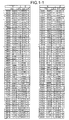
- Figs. 1-1 to 1-3 are tables showing correspondence between eight-bit input data and the number of '1's (hereinafter, "POP") in the data represented as a binary number.
- Figs. 1-1 to 1-3 depict eight-bit data (X ⁇ 7:0>) having 256 possible values, from "00000000” to "11111111", values of parity (X ⁇ P>) of the input data, POP (Z ⁇ 3:0>), and parity (Z ⁇ P>) of the POP.
- the POP can take values from "0000 (0 in the decimal notation)" to "1000 (8 in the decimal notation)".
- Figs.1-1 to 1-3 an odd parity is employed, and "1" is set as the parity of the eight-bit input data "00000000”.
- Fig. 2 depicts data extracted from the data shown in Figs. 1-1 to 1-3 (data marked with "*") in which the parity of the input data matches the parity of the POP.
- the POP takes any one of "0000” (0 in the decimal notation), "0001” (1 in the decimal notation), "0110” (6 in the decimal notation), and "0111” (7 in the decimal notation).
- the POP takes any one of "0010” (2 in the decimal notation), "0011” (3 in the decimal notation), “0100 (4 in the decimal notation)", “0101” (5 in the decimal notation), and "1000” (8 in the decimal notation).
- the parity of POP can be predicted in the following manner. That is, in obtaining the POP of eight-bit input data, when the POP is any one of "0", “1", “6", and "7", it is expected that the parity of the POP is the same as the parity of the input data. When the POP has other values, it is expected that the parity of the POP is an inverted value of the parity of the input data.
- the parity can be predicted by dividing the input data into eight-bit portions. Specifically, the parity of the POP of each eight-bit portion is predicted according to the above rule, and the parity of the POP of the input data can be predicted by summing the prediction results.
- the cycle time of the parity predicting process in the parity predicting system of the present embodiment needs to be equal to or shorter than the cycle time of the population count operation.
- the cycle time of the parity predicting process is equal to or shorter than that of the population count operation, the parity predicting process is masked by the population count operation, and does not affect the execution time of the POP instruction.
- the POP of input data needs to be determined. However, this determination is sufficient if it can be determined whether the POP is any one of "0", “1", “6”, and “7” in the decimal notation or any one of "2", “3”, “4", "5", and “8” in the decimal notation. Therefore, the POP does not need to be calculated using the combination of adders as disclosed in Patent Document 1, and the execution speed can be increased by realizing a determining circuit using a decoder.
- the circuit size increases. Consequently, the processing is performed by dividing the eight-bit input data into the upper four-bit data and the lower four-bit data.
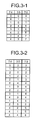
- Fig. 3-1 depicts all combinations of the POP of the upper four bits ( ⁇ 7:4>) and the POP of the lower four bits ( ⁇ 3:0>) when the POP of the eight-bit input data takes any one of "0", "1", "6", and "7" in the decimal notation. As shown in Fig. 3-1 , there are eight combinations in this case.
- Fig. 3-2 depicts all combinations of the POP of the upper four bits and the POP of the lower four bits when the POP of the eight-bit input data takes any one of "2", “3", “4", "5", and "8" in the decimal notation. As shown in Fig. 3-2 , there are 15 combinations in this case.
- the circuit size for achieving the parity prediction can be reduced by determining whether the POP of the eight-bit input data is any one of "0", “1", “6", and “7” in the decimal notation consisting of eight combinations as compared to by determining whether the POP of the data is any one of "2", “3", “4", "5", and "8” in the decimal notation consisting of 15 combinations.
- the following example describes determination as to whether the POP of eight-bit input data is any one of "0”, “1”, “6", and “7” in the decimal notation is made by dividing the input data into an upper-bit portion and a lower-bit portion.
- whether the POP of eight-bit input data is any one of "2" "3" "4", "5", and "8" in the decimal notation can be determined by dividing the input data into an upper-bit portion and a lower-bit portion.
- the determination can be performed without dividing the eight-bit input data into upper four-bit data and lower four-bit data.
- Fig. 4 is a block diagram of a configuration of a population counter circuit corresponding to eight-bit input data.
- a population counter circuit 100 receives eight-bit input data (X ⁇ 7:0>) and its parity (X ⁇ P>), and outputs a operation result (Z ⁇ 3:0>) of the population count and its parity (Z ⁇ P>).
- the population counter circuit 100 includes a population counting unit 1000, a parity predicting unit 2000, and a parity inverting circuit 3000.
- the population counting unit 1000 receives the eight-bit input data (X ⁇ 7:0>), counts POP of this data, and outputs the operation result (Z ⁇ 3:0>).
- the population counting unit 1000 includes a combination of a CAS (Carry Save Adder), and a HA (Half Adder).
- the configuration of the population counting unit 1000 need not necessarily be as illustrated in Fig. 4 , and can be, for example, as disclosed in Patent Document 1.
- the parity predicting unit 2000 and the parity inverting circuit 3000 predict the parity of the operation result using the parity predicting system of the present embodiment.
- the parity predicting unit 2000 receives and decodes the eight-bit input data (X ⁇ 7:0>).
- the parity predicting unit 2000 outputs 0 as an INV_P signal when the POP of the data is any one of "0", "1", "6", and "7" in the decimal notation, and otherwise outputs 1.
- the parity inverting unit 3000 When the INV_P signal is 0, the parity inverting unit 3000 directly outputs the parity (X ⁇ P>) of the input data as the parity (Z ⁇ P>) of the operation result.
- the parity inverting unit 3000 When the INV_P signal is 1, the parity inverting unit 3000 outputs an inversion of the parity (X ⁇ P>) of the input data as the parity (Z ⁇ P>) of the operation result.
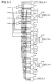
- Figs. 5-1 to 5-3 are block diagrams of a configuration of the parity predicting unit 2000.
- Fig. 5-1 depicts a circuit configuration for determination by decoding the POP of the upper four bits (X ⁇ 7:4>) of the input data.
- NOT circuits 2111 to 2114 invert the input bits X ⁇ 7> to X ⁇ 4>, respectively.
- AND circuits 2121, 2131 to 2134, 2141 to 2146, 2151 to 2154, and 2161 are configured as decoding circuits that decode inputs of signals obtained by inverting a part or all of the input bits X ⁇ 7> to X ⁇ 4>, using the NOT circuits 2111 to 2114, so that only one circuit outputs 1 corresponding to a bit pattern of the input bits X ⁇ 7> to X ⁇ 4>, and other circuits output 0.
- the AND circuit 2121 When the POP of the upper four bits is 0, i.e., when all bits are 0, the AND circuit 2121 outputs 1. This output is a POPC_74_0 signal.
- any one of the AND circuits 2131 to 2134 outputs 1.
- An OR circuit 2135 calculates a logical sum of these outputs, and outputs a POPC_74_1 signal.
- any one of the AND circuits 2141 to 2146 outputs 1.
- An OR circuit 2147 calculates a logical sum of these outputs, and outputs a POPC_74_2 signal.
- any one of the AND circuits 2151 to 2154 outputs 1.
- An OR circuit 2155 calculates a logical sum of these outputs, and outputs a POPC_74_3 signal.
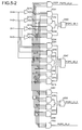
- Fig. 5-2 depicts a circuit configuration for determining the POP of the lower four bits (X ⁇ 3:0>) of the input data.
- the configuration of the circuit is similar to that shown in Fig. 5-1 , and therefore only signals to be output are explained.
- a POPC_30_0 signal is 1 when the POP of the lower four bits is 0.
- a POPC_30_1 signal is 1 when the POP of the lower four bits is 1.
- a POPC_30_2 signal is 1 when the POP of the lower four bits is 2, and a POPC_30_3 signal is 1 when the POP of the lower four bits is 3.
- a POPC_30_4 signal is 1 when the POP of the lower four bits is "4" in the decimal notation.
- Fig. 5-3 depicts a circuit configuration for determining whether the POP of the eight-bit input data (X ⁇ 7:0>) is any one of "0", “1", “6", and "7" in the decimal notation.
- AND circuits 2311, 2321 to 2322, 2331 to 2333, and 2341 to 2342 determine a value of the POP of the eight-bit input data (X ⁇ 7:0>) based on combinations of determination results of the POP of the upper four bits (X ⁇ 7:4>) and the POP of the lower four bits (X ⁇ 3:0>).
- the AND circuit 2311 outputs 1 when the POP of the upper four bits is 0 and when the POP of the lower four bits is 0, i.e., when the POPC_74_0 signal is 1 and when the POPC_30_0 signal is 1. This output is a POPC_70_0 signal.
- the AND circuit 2321 outputs 1 when the POP of the upper four bits is 0 and when the POP of the lower four bits is "1" in the decimal notation, i.e., when the POPC_74_0 signal is 1 and when the POPC_30_1 signal is 1.
- the AND circuit 2322 outputs 1 when the POP of the upper four bits is 1 and when the POP of the lower four bits is "0" in the decimal notation, i.e., when the POPC_74_1 signal is 1 and when the POPC_30_0 signal is 1.
- An OR circuit 2323 calculates a logical sum of the outputs of the AND circuit 2321 and the AND circuit 2322, and outputs a POPC_70_1 signal.
- the AND circuit 2331 outputs 1 when the POP of the upper four bits is 4 and when the POP of the lower four bits is "2" in the decimal notation, i.e., when the POPC_74_4 signal is 1 and when the POPC_30_2 signal is 1.
- the AND circuit 2332 outputs 1 when the POP of the upper four bits is 3 and when the POP of the lower four bits is "3" in the decimal notation, i.e., when the POPC_74_3 signal is 1 and when the POPC_30_3 signal is 1.
- the AND circuit 2333 outputs 1 when the POP of the upper four bits is 2 and when the POP of the lower four bits is "4" in the decimal notation, i.e., when the POPC_74_2 signal is 1 and when the POPC_30_4 signal is 1.
- An OR circuit 2334 calculates a logical sum of the outputs of the AND circuit 2331, the AND circuit 2332, and the AND circuit 2333, and outputs a POPC_70_6 signal.
- the AND circuit 2341 outputs 1 when the POP of the upper four bits is "4" in the decimal notation and when the POP of the lower four bits is "3" in the decimal notation, i.e., when the POPC_74_4 signal is 1 and when the POPC_30_3 signal is 1.
- the AND circuit 2342 outputs 1 when the POP of the upper four bits is “3" in the decimal notation and when the POP of the lower four bits is "4" in the decimal notation, i.e., when the POPC_74_3 signal is 1 and when the POPC_30_4 signal is 1.
- An OR circuit 2343 calculates a logical sum of the outputs of the AND circuit 2341 and the AND circuit 2342, and outputs a POPC_70_7 signal.
- An NOR circuit 2351 calculates a logical sum of the POPC_70_0 signal, the POPC_70_1 signal, the POPC_70_6 signal, and the POPC_70_7 signal, and outputs an inversion of the operation result as an INV_P signal.
- the INV_P signal as an output of the parity predicting unit 2000 is 0 when the POP of the eight-bit input data (X ⁇ 7:0>) is any one of "0", “1", “6", and “7” in the decimal notation, and is 1 when the POP is other value.
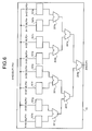
- Fig. 6 is a block diagram of a configuration of a population counter circuit corresponding to 64-bit input data.
- a population counter circuit 10 receives 64-bit input data (X ⁇ 63:00>) and its parities (X ⁇ 7:P0>) each corresponding to eight bits, and outputs a operation result (Z ⁇ 6:0>) of the population count and its parity (Z ⁇ P>).
- the population counter circuit 10 includes population counter circuits 101a to 101h, and adder circuits 201a to 201g.
- the population counter circuits 101a to 101h are similar to the population counter circuit 100, and each receive eight-bit input data and its parity and output a POP and its parity.
- the population counter circuit 101a receives lowest eight bits (X ⁇ 07:00>) of the input data and their parity (X ⁇ P0).
- the population counter circuit 101b receives upper eight bits (X ⁇ 15:08>) and their parity (X ⁇ P1>).
- the population counter circuit 101c receives upper eight bits (X ⁇ 23:16>) and their parity (X ⁇ P2>).
- the population counter circuit 101d receives upper eight bits (X ⁇ 31:24>) and their parity (X ⁇ P3>).
- the population counter circuit 101e receives upper eight bits (X ⁇ 39:32>) and their parity (X ⁇ P4>).
- the population counter circuit 101f receives upper eight bits (X ⁇ 47:40>) and their parity (X ⁇ P5>).
- the population counter circuit 101g receives upper eight bits (X ⁇ 55:48>) and their parity (X ⁇ P6>).
- the population counter circuit 101h receives upper eight bits (X ⁇ 63:56>) of the input data and their parity (X ⁇ P7>).
- the adder circuits 201a to 201g add POPs and parities, and output an addition result of the POPs and an addition result of the parities.
- the adder circuit 201a adds together the addition result and the parity result from the population counter circuit 101a, and the addition result and the parity result from the population counter circuit 101b, respectively.
- the adder circuit 201b adds together the addition result and the parity result from the population counter circuit 101c, and the addition result and the parity result from the population counter circuit 101d, respectively.
- the adder circuit 201c adds together the addition result and the parity result from the population counter circuit 101e, and the addition result and the parity result from the population counter circuit 101f, respectively.
- the adder circuit 201d adds together the addition result and the parity result from the population counter circuit 101g, and the addition result and the parity result from the population counter circuit 101h, respectively.
- the adder circuit 201e adds together the addition result and the parity result from the adder circuit 201a, and the addition result and the parity result from the adder circuit 201b, respectively.
- the adder circuit 201f adds together the addition result and the parity result from the adder circuit 201c, and the addition result and the parity result from the adder circuit 201d, respectively.
- the adder circuit 201g adds together the addition result and the parity result from the adder circuit 201e, and the addition result and the parity result from the adder circuit 201f, respectively.
- a result of the addition by the adder circuit 201g is output as the result of the population count (Z ⁇ 6:0>) and the parity (Z ⁇ P>).
- the POP can be counted and the parity can be predicted with population counter circuits corresponding to eight-bit input data arranged in parallel and adder circuits that add the output results.
- a population counter circuit corresponding to a bit width larger than 64 bits can also be realized as shown in Fig. 7 .
- the parity generation circuit, the counter circuit, and the counting method of the present invention are useful for counting the number of '1's in decimal data.
- the present invention is effective for high-speed calculation of the parity of a result of population count without affecting the cycle time of the calculation.
Landscapes
- Engineering & Computer Science (AREA)
- Theoretical Computer Science (AREA)
- Physics & Mathematics (AREA)
- Probability & Statistics with Applications (AREA)
- General Physics & Mathematics (AREA)
- General Engineering & Computer Science (AREA)
- Computing Systems (AREA)
- Mathematical Physics (AREA)
- Pure & Applied Mathematics (AREA)
- Mathematical Optimization (AREA)
- Mathematical Analysis (AREA)
- Computational Mathematics (AREA)
- Quality & Reliability (AREA)
- Detection And Correction Of Errors (AREA)
- Error Detection And Correction (AREA)
Applications Claiming Priority (1)
| Application Number | Priority Date | Filing Date | Title |
|---|---|---|---|
| PCT/JP2006/300749 WO2007083377A1 (ja) | 2006-01-19 | 2006-01-19 | パリティ生成回路、計数回路および計数方法 |
Publications (2)
| Publication Number | Publication Date |
|---|---|
| EP1978643A1 true EP1978643A1 (de) | 2008-10-08 |
| EP1978643A4 EP1978643A4 (de) | 2010-06-09 |
Family
ID=38287339
Family Applications (1)
| Application Number | Title | Priority Date | Filing Date |
|---|---|---|---|
| EP06711995A Withdrawn EP1978643A4 (de) | 2006-01-19 | 2006-01-19 | Paritätserzeugungsschaltung, zähler und zählverfahren |
Country Status (6)
| Country | Link |
|---|---|
| US (1) | US8296641B2 (de) |
| EP (1) | EP1978643A4 (de) |
| JP (1) | JP4567753B2 (de) |
| KR (1) | KR101007259B1 (de) |
| CN (1) | CN101361278B (de) |
| WO (1) | WO2007083377A1 (de) |
Families Citing this family (4)
| Publication number | Priority date | Publication date | Assignee | Title |
|---|---|---|---|---|
| WO2006106576A1 (ja) * | 2005-03-31 | 2006-10-12 | Fujitsu Limited | パリティ予測回路及びこれを使用した論理演算回路 |
| US10146537B2 (en) * | 2015-03-13 | 2018-12-04 | Micron Technology, Inc. | Vector population count determination in memory |
| TWI671750B (zh) * | 2018-11-28 | 2019-09-11 | 華邦電子股份有限公司 | 記憶體的控制方法及非暫態電腦可讀媒體 |
| CN116974514B (zh) * | 2023-07-21 | 2024-02-02 | 北京市合芯数字科技有限公司 | 位值计数电路装置、处理器芯片及位值计数方法 |
Family Cites Families (16)
| Publication number | Priority date | Publication date | Assignee | Title |
|---|---|---|---|---|
| JPS5967729A (ja) | 1982-10-12 | 1984-04-17 | Nec Corp | デクリメント・カウンタ論理回路 |
| US4710934A (en) * | 1985-11-08 | 1987-12-01 | Texas Instruments Incorporated | Random access memory with error correction capability |
| JPS647830A (en) * | 1987-06-30 | 1989-01-11 | Nec Corp | Transmission line code error monitoring system |
| JP2595277B2 (ja) * | 1988-01-12 | 1997-04-02 | 株式会社日立製作所 | メモリ管理装置 |
| JPH03105670A (ja) * | 1989-09-20 | 1991-05-02 | Fujitsu Ltd | ポピュレーション・カウント機能をもつ乗加算装置 |
| JP3158215B2 (ja) * | 1991-10-04 | 2001-04-23 | 富士通株式会社 | パリティ反転試験方式 |
| JP3105670B2 (ja) | 1992-11-26 | 2000-11-06 | 富士通株式会社 | 荷電粒子ビーム露光装置及びその制御方法 |
| US5717616A (en) | 1993-02-19 | 1998-02-10 | Hewlett-Packard Company | Computer hardware instruction and method for computing population counts |
| US5522032A (en) * | 1994-05-05 | 1996-05-28 | International Business Machines Corporation | Raid level 5 with free blocks parity cache |
| JPH10333991A (ja) | 1997-06-02 | 1998-12-18 | Matsushita Electric Ind Co Ltd | データ書込及び読出の誤り検出方法並びに半導体装置の自己検査方法 |
| US5936972A (en) * | 1997-06-18 | 1999-08-10 | Motorola, Inc. | Syndrome-based channel quality or message structure determiner |
| JPH1117556A (ja) | 1997-06-27 | 1999-01-22 | Sony Corp | ディジタル信号処理装置および方法 |
| CN1119884C (zh) * | 2000-02-23 | 2003-08-27 | 华为技术有限公司 | 高速数据传输中的差错检测方法 |
| KR100913467B1 (ko) * | 2002-11-19 | 2009-08-25 | 엘지전자 주식회사 | 병렬 순환 중복 검사 코드 발생 시스템 및 방법 |
| US7475301B2 (en) * | 2003-05-09 | 2009-01-06 | Hewlett-Packard Development Company, L.P. | Increment/decrement circuit for performance counter |
| JP4319533B2 (ja) | 2003-12-04 | 2009-08-26 | 富士通株式会社 | ポピュレーションカウント回路 |
-
2006
- 2006-01-19 JP JP2007554774A patent/JP4567753B2/ja not_active Expired - Fee Related
- 2006-01-19 CN CN2006800514174A patent/CN101361278B/zh not_active Expired - Fee Related
- 2006-01-19 WO PCT/JP2006/300749 patent/WO2007083377A1/ja not_active Ceased
- 2006-01-19 EP EP06711995A patent/EP1978643A4/de not_active Withdrawn
- 2006-01-19 KR KR1020087017169A patent/KR101007259B1/ko not_active Expired - Fee Related
-
2008
- 2008-07-18 US US12/219,313 patent/US8296641B2/en not_active Expired - Fee Related
Also Published As
| Publication number | Publication date |
|---|---|
| CN101361278A (zh) | 2009-02-04 |
| EP1978643A4 (de) | 2010-06-09 |
| WO2007083377A1 (ja) | 2007-07-26 |
| JPWO2007083377A1 (ja) | 2009-06-11 |
| US8296641B2 (en) | 2012-10-23 |
| CN101361278B (zh) | 2012-02-01 |
| KR101007259B1 (ko) | 2011-01-13 |
| JP4567753B2 (ja) | 2010-10-20 |
| US20080282136A1 (en) | 2008-11-13 |
| KR20080083321A (ko) | 2008-09-17 |
Similar Documents
| Publication | Publication Date | Title |
|---|---|---|
| US5862065A (en) | Method and circuit for fast generation of zero flag condition code in a microprocessor-based computer | |
| US9146707B2 (en) | Generating a fast 3x multiplicand term for radix-8 booth multiplication | |
| EP0018519A1 (de) | Multipliziereinrichtung, die einen Addierer mit Übertrags-Speicherung/- Fortpflanzung enthält | |
| JPH07210369A (ja) | 並列加算および平均演算を行うための回路およびその方法 | |
| US3986015A (en) | Arithmetic unit for use in a digital data processor and having an improved system for parity check bit generation and error detection | |
| US8296641B2 (en) | Parity generation circuit, counter circuit, and counting method | |
| US5097436A (en) | High performance adder using carry predictions | |
| US20080148011A1 (en) | Carry/Borrow Handling | |
| US7016932B2 (en) | Adders and adder bit blocks having an internal propagation characteristic independent of a carry input to the bit block and methods for using the same | |
| EP1983434B1 (de) | Paritätserzeugungsschaltung, anordnungsschaltung für eine paritätserzeugungsschaltung, informationsverarbeitungsvorrichtung und codierer | |
| US8219604B2 (en) | System and method for providing a double adder for decimal floating point operations | |
| US7415580B2 (en) | System for determining the position of an element in memory | |
| US7024439B2 (en) | Leading Zero Anticipatory (LZA) algorithm and logic for high speed arithmetic units | |
| JPH09222991A (ja) | 加算方法および加算器 | |
| US20220326911A1 (en) | Product-sum calculation device and product-sum calculation method | |
| JP4317738B2 (ja) | 平均値算出装置および平均値算出方法 | |
| US6631393B1 (en) | Method and apparatus for speculative addition using a limited carry | |
| US7739323B2 (en) | Systems, methods and computer program products for providing a combined moduli-9 and 3 residue generator | |
| EP0992884B1 (de) | Verfahren und Vorrichtung zur Antizipation eines Ergebnisses Null | |
| RU2399157C2 (ru) | Декодер сверточных кодов для dvb-t приемника | |
| US6748411B1 (en) | Hierarchical carry-select multiple-input split adder | |
| US20080307032A1 (en) | Divider Circuit | |
| US7225218B2 (en) | Apparatus and methods for generating counts from base values | |
| US6820109B2 (en) | System and method for predictive comparator following addition | |
| JP3482102B2 (ja) | 絶対値距離演算回路 |
Legal Events
| Date | Code | Title | Description |
|---|---|---|---|
| PUAI | Public reference made under article 153(3) epc to a published international application that has entered the european phase |
Free format text: ORIGINAL CODE: 0009012 |
|
| 17P | Request for examination filed |
Effective date: 20080813 |
|
| AK | Designated contracting states |
Kind code of ref document: A1 Designated state(s): DE FR GB |
|
| DAX | Request for extension of the european patent (deleted) | ||
| RBV | Designated contracting states (corrected) |
Designated state(s): DE FR GB |
|
| RIC1 | Information provided on ipc code assigned before grant |
Ipc: G06F 11/10 20060101ALI20100428BHEP Ipc: G06F 7/505 20060101ALI20100428BHEP Ipc: H03M 13/09 20060101AFI20070906BHEP |
|
| A4 | Supplementary search report drawn up and despatched |
Effective date: 20100510 |
|
| STAA | Information on the status of an ep patent application or granted ep patent |
Free format text: STATUS: THE APPLICATION HAS BEEN WITHDRAWN |
|
| 18W | Application withdrawn |
Effective date: 20141212 |