EP1978345A2 - Verfahren zur Schätzung der Größe einer Kraft, die auf einen rollenden Reifen einwirkt - Google Patents
Verfahren zur Schätzung der Größe einer Kraft, die auf einen rollenden Reifen einwirkt Download PDFInfo
- Publication number
- EP1978345A2 EP1978345A2 EP08004716A EP08004716A EP1978345A2 EP 1978345 A2 EP1978345 A2 EP 1978345A2 EP 08004716 A EP08004716 A EP 08004716A EP 08004716 A EP08004716 A EP 08004716A EP 1978345 A2 EP1978345 A2 EP 1978345A2
- Authority
- EP
- European Patent Office
- Prior art keywords
- tire
- strain
- sensors
- magnitude
- measuring
- Prior art date
- Legal status (The legal status is an assumption and is not a legal conclusion. Google has not performed a legal analysis and makes no representation as to the accuracy of the status listed.)
- Granted
Links
- 238000000034 method Methods 0.000 title claims abstract description 25
- 238000005096 rolling process Methods 0.000 title claims abstract description 18
- 239000011159 matrix material Substances 0.000 claims abstract description 10
- 239000011324 bead Substances 0.000 claims description 12
- 229920001971 elastomer Polymers 0.000 claims description 2
- 239000000806 elastomer Substances 0.000 claims description 2
- 239000000463 material Substances 0.000 claims description 2
- 238000012886 linear function Methods 0.000 description 8
- 230000007935 neutral effect Effects 0.000 description 3
- 238000010586 diagram Methods 0.000 description 2
- 230000000694 effects Effects 0.000 description 2
- 238000002474 experimental method Methods 0.000 description 2
- 230000008520 organization Effects 0.000 description 2
- 230000001012 protector Effects 0.000 description 2
- 229920002725 thermoplastic elastomer Polymers 0.000 description 2
- 229920001875 Ebonite Polymers 0.000 description 1
- 238000005266 casting Methods 0.000 description 1
- 238000013461 design Methods 0.000 description 1
- 238000001746 injection moulding Methods 0.000 description 1
- 238000005259 measurement Methods 0.000 description 1
- 238000000465 moulding Methods 0.000 description 1
- 238000012545 processing Methods 0.000 description 1
- 230000003014 reinforcing effect Effects 0.000 description 1
- 230000004044 response Effects 0.000 description 1
- 239000004065 semiconductor Substances 0.000 description 1
- 230000035945 sensitivity Effects 0.000 description 1
- 230000003068 static effect Effects 0.000 description 1
- 239000002344 surface layer Substances 0.000 description 1
- 239000000725 suspension Substances 0.000 description 1
Images


Classifications
-
- G—PHYSICS
- G01—MEASURING; TESTING
- G01L—MEASURING FORCE, STRESS, TORQUE, WORK, MECHANICAL POWER, MECHANICAL EFFICIENCY, OR FLUID PRESSURE
- G01L5/00—Apparatus for, or methods of, measuring force, work, mechanical power, or torque, specially adapted for specific purposes
- G01L5/20—Apparatus for, or methods of, measuring force, work, mechanical power, or torque, specially adapted for specific purposes for measuring wheel side-thrust
-
- B—PERFORMING OPERATIONS; TRANSPORTING
- B60—VEHICLES IN GENERAL
- B60C—VEHICLE TYRES; TYRE INFLATION; TYRE CHANGING; CONNECTING VALVES TO INFLATABLE ELASTIC BODIES IN GENERAL; DEVICES OR ARRANGEMENTS RELATED TO TYRES
- B60C23/00—Devices for measuring, signalling, controlling, or distributing tyre pressure or temperature, specially adapted for mounting on vehicles; Arrangement of tyre inflating devices on vehicles, e.g. of pumps or of tanks; Tyre cooling arrangements
- B60C23/06—Signalling devices actuated by deformation of the tyre, e.g. tyre mounted deformation sensors or indirect determination of tyre deformation based on wheel speed, wheel-centre to ground distance or inclination of wheel axle
- B60C23/064—Signalling devices actuated by deformation of the tyre, e.g. tyre mounted deformation sensors or indirect determination of tyre deformation based on wheel speed, wheel-centre to ground distance or inclination of wheel axle comprising tyre mounted deformation sensors, e.g. to determine road contact area
-
- G—PHYSICS
- G01—MEASURING; TESTING
- G01L—MEASURING FORCE, STRESS, TORQUE, WORK, MECHANICAL POWER, MECHANICAL EFFICIENCY, OR FLUID PRESSURE
- G01L5/00—Apparatus for, or methods of, measuring force, work, mechanical power, or torque, specially adapted for specific purposes
- G01L5/16—Apparatus for, or methods of, measuring force, work, mechanical power, or torque, specially adapted for specific purposes for measuring several components of force
- G01L5/169—Apparatus for, or methods of, measuring force, work, mechanical power, or torque, specially adapted for specific purposes for measuring several components of force using magnetic means
-
- B—PERFORMING OPERATIONS; TRANSPORTING
- B60—VEHICLES IN GENERAL
- B60C—VEHICLE TYRES; TYRE INFLATION; TYRE CHANGING; CONNECTING VALVES TO INFLATABLE ELASTIC BODIES IN GENERAL; DEVICES OR ARRANGEMENTS RELATED TO TYRES
- B60C19/00—Tyre parts or constructions not otherwise provided for
- B60C2019/004—Tyre sensors other than for detecting tyre pressure
-
- Y—GENERAL TAGGING OF NEW TECHNOLOGICAL DEVELOPMENTS; GENERAL TAGGING OF CROSS-SECTIONAL TECHNOLOGIES SPANNING OVER SEVERAL SECTIONS OF THE IPC; TECHNICAL SUBJECTS COVERED BY FORMER USPC CROSS-REFERENCE ART COLLECTIONS [XRACs] AND DIGESTS
- Y10—TECHNICAL SUBJECTS COVERED BY FORMER USPC
- Y10T—TECHNICAL SUBJECTS COVERED BY FORMER US CLASSIFICATION
- Y10T152/00—Resilient tires and wheels
- Y10T152/10—Tires, resilient
- Y10T152/10495—Pneumatic tire or inner tube
Definitions
- the present invention relates to a method for estimating the magnitude of a force acting on a rolling tire based on the strain caused in the tire sidewall portion.
- CAVCS computer-aided vehicle control systems
- ABS anti-lock brake system
- traction control system traction control system
- vehicle stability control system attitude control system
- suspension control system suspension control system and steer-by-wire system and the like
- CAVCS control system
- a primary object of the present invention is therefore, to provide a method for estimating the magnitude of a force component acting on a rolling tire such as tire air pressure, longitudinal force and the like based on the strain caused in the tire sidewall portion.
- Another object of the present invention is to detect a tire pressure drop, based on a comparison between the estimated air pressure and a predetermined reference pressure.
- Still another object of the present invention is to estimate the magnitude of the longitudinal force by the use of strain sensor(s) as less as possible.
- a method for estimating the magnitude of a tire force acting on a rolling tire comprises:
- the method further comprises:
- the method further comprises:
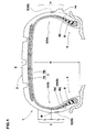
- pneumatic tire 1 comprises: a tread portion 2; a pair of axially spaced bead portions 4 each with a bead core 5 therein; a pair of sidewall portions 3 (3i, 3o) extending between the tread edges Te and the bead portions 4; a carcass 6 extending between the bead portions 4; a tread reinforcing belt 7 disposed radially outside the carcass 6; and strain sensors S fixed to at least one of the sidewall portions 3.
- the tire 1 is a radial tire of size 225/55R17 for passenger cars.
- the carcass 6 is composed of at least one ply 6A of cords arranged radially at an angle in the range of from 70 to 90 degrees with respect to the tire equator, extending between the bead portions 4 through the tread portion 2 and sidewall portions 3 and turned up around the bead core 5 in each bead portion 4 from the axially inside to the axially outside of the tire to form a pair of turnup portions 6b and a main portion 6a therebetween. Between the main portion 6a and each turned up portion 6b, a bead apex 8 made of a hard rubber is disposed so as to extend radially outwardly from the bead core while tapering towards its radially outer end.
- the belt comprises a breaker 7 and optionally a band 9.
- the breaker 7 comprises: at least two cross plies 7A and 7B of high modulus cords laid at an angle of from 10 to 35 degrees with respect to the tire equator.
- the band 9 is disposed on the radially outside of the breaker 7 and composed of a cord or cords wound at a small angle of at most about 5 degrees with respect to the tire equator.
- one sidewall portion 3i has a typical outer profile, whereas the other sidewall portion 3o has a peculiar outer profile.
- the profile refers to that under the normally inflated unloaded condition of the tire.
- the normally inflated unloaded condition is such that the tire is mounted on a standard wheel rim and inflate to a standard pressure but loaded with no tire load.
- the standard wheel rim is a wheel rim officially approved for the tire by standard organization, i.e. JATMA (Japan and Asia), T&RA (North America), ETRTO (Europe), STRO (Scandinavia) and the like.
- the standard pressure and the standard tire load are the maximum air pressure and the maximum tire load for the tire specified by the same organization in the Air-pressure/Maximum-load Table or similar list.
- the standard wheel rim is the "standard rim” specified in JATMA, the “Measuring Rim” in ETRTO, the “Design Rim” in TRA or the like.
- the standard pressure is the “maximum air pressure” in JATMA, the “Inflation Pressure” in ETRTO, the maximum pressure given in the “Tire Load Limits at various Cold Inflation Pressures” table in TRA or the like.
- the standard load is the "maximum load capacity" in JATMA, the “Load Capacity” in ETRTO, the maximum value given in the above-mentioned table in TRA or the like. In case of passenger car tires, however, the standard pressure is uniformly defined by 180 kPa.
- the outer profile 11 is substantially a continuously curved convex line, with the exception of possible various markings, decorative small grooves, ribs and the like. Usually, the outer profile is almost parallel with or similar to the profile of the carcass main portion 6a.
- an axially-outward protrusion 14 is formed in the lower sidewall portion.
- the protrusion 14 protrudes from the above-explained typical outer profile 11 largely when compared with the possible decorative small ribs and the like, and the peculiar outer profile is formed as described later.
- At least one of the sidewall portions 3i and 3o is provided with a plurality of sensors S to sense strain of the outer surface (or surface layer).
- the type of the sensor S various types can be used as far as the sensor S can sense the surface strain ⁇ and output an electronic data indicative of the magnitude (t) of the sensed strain ⁇ .
- the sensor should be heat-stable and mechanically stable and durable.
- piezoelectric element, wire resistance strain gauge and the like can be used as the sensor S, it is preferred to use a combination of a magnet 11 and an magnetometric sensor element 12. In such combination, at least one magnet 11 and at least one magnetometric sensor element 12 are embedded in a molded resilient body 13 as one unit 20.
- the resilient body 13 has to deform following the deformation of the tire sidewall portion 3, therefore, an elastomer material is used.
- thermoplastic elastomer TPE
- various types of elements for example, hall element, MR element, TMF-MI sensor, TMF-FG sensor, amorphous sensor and the like can be used.
- a hall element is used.
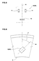
- Figs.3 to 5 show examples of such magnet type sensor unit 20.
- the sensor unit 20 includes a single magnetometric sensor element 12 and a single magnet 11.
- the sensor unit 20 includes a plurality of magnetometric sensor elements 12 and a single magnet 11.
- the sensor unit 20 includes a single magnetometric sensor element 12 and a plurality of magnets 11.
- the sensor units 20 each have a directional sensibility, and the maximum sensibility occurs in a direction N.
- the sensor S or sensor unit 20 is oriented such that the angle theta between the maximum sensibility direction N and the tire radial direction becomes in a range of 10 to 80 degrees, preferably 20 to 70 degrees in view of the overall accuracy, more preferably 30 to 60 degrees, still more preferably 40 to 50 degrees when viewed from the side of the tire.
- the angle theta is set at 45 degrees.
- the above-mentioned magnitude (t) of the sensed strain ⁇ means that of the strain ⁇ measured with the sensor S having a particular directional sensibility oriented towards a particular direction, thus, it is not always the same as the magnitude of the maximum strain perhaps occurring in a certain direction.
- a wireless connection is used.
- the above-mentioned sensor unit 20 contains a transponder which can transmit the date indicative of the magnitude (t) towards the electrical control unit mounted on the vehicle body side, in response to a query signal sent via an electromagnetic wave from the electrical control unit.
- Such transponder comprises a receiver, a transmitter, control circuit, data memory and the like which are formed on a semiconductor chip, and an antenna. Further, in order to utilize the above-mentioned electromagnetic wave as the source of electric energy, a converter and an electric accumulator/condenser are also incorporated in the unit 20.
- the transponder 16 is formed separately from the sensor unit 20 and attached to a stable portion of the tire such as the inside of the bead portion, or in the rim well of the wheel rim on which the tire is mounted. And the transponder 16 is connected to the sensor units 20 by electric wires 17 embedded in the tire when making the tire.
- the magnitude of the strain ⁇ has a substantially linear correlation with the magnitude of each of seven force components (longitudinal force Fx, side force Fy, vertical load Fz, overturning moment Mx, rolling resistance moment My, self-aligning torque Mz, and air pressure P).
- Such region Y may extend radially inward and outward from the midpoint M by a radial distance L of 25% of the tire section height H at the maximum.
- the distance L is considered to be not more than 20%, more preferably not more than 15% of the tire section height H.
- the above-mentioned midpoint M is located at 50% of the tire section height H, and the tire section height H is measured from the bead base line BL to the tread surface at the tire equator C.
- ⁇ 1 a ⁇ 1 • Fx + b ⁇ 1 • Fy + c ⁇ 1 • Fz + d ⁇ 1 • Mx + e ⁇ 1 • My + g ⁇ 1 • Mz + h ⁇ 1 •
- P ⁇ 2 a ⁇ 2 • Fx + b ⁇ 2 • Fy + c ⁇ 2 • Fz + d ⁇ 2 • Mx + e ⁇ 2 • My + g ⁇ 2 • Mz + h ⁇ 2 •
- P ⁇ 3 a ⁇ 3 • Fx + b ⁇ 3 • Fy + c ⁇ 3 • Fz + d ⁇ 3 • Mx + e ⁇ 3 • My + g ⁇ 3 • Mz + h ⁇ 3 •
- P ⁇ 4 a ⁇ 4 • F
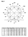
- the coefficients "a, b, c, d, e, g and h" for each of the measuring position J1-J7 are determined in advance through an experiment.
- the overall surface strain ⁇ is measured at each measuring position, and by making a numerical analysis on the measured values ⁇ and the magnitudes of the applied force components P, Fx, Fy, Fz, Mx, My and Mz, with a computer, the coefficients are determined.
- the strain ⁇ has to be measured at seven different positions J1-J7 simultaneously. Therefore, at least seven strain sensors S have to be mounted on the tire sidewall portion at circumferentially different positions.
- a sensor arrangement shown in Fig.7 therefore, eight sensors S are used. All of the sensors s are arranged equiangularly around the tire rotational axis at the same radial height or position.
- the interval of outputting the estimated data during running it is desirable that the interval is as short as possible if permitted by the data processor although it is not always necessary if the air pressure P is the only force component to be obtained. In the case of the air pressure P only, the interval may be relatively long, for example once per one tire revolution.
- the eight sensors S1-S8 are arranged at regular intervals of 45 degrees around the tire rotational axis. And eight positions P1-P8 for use as the measuring positions J1-J7 are prepared in advance at regular intervals of 45 degrees.
- the sensors S are moved around the tire rotational axis as the tire rotates since the sensors S are fixed to the tire sidewall portion 3, but, the positions P1-P8, namely, the measuring positions J1-J7 are fixed to a static polar coordinate system having the origin set at the tire rotational axis and being parallel with the tire equatorial plane.
- the polar angle of zero can be set at any direction, but in the illustrated example, for the sake of convenience, it is set at the vertically downward direction. Therefore, the polar angles of the polar coordinates of the positions P1-P8 are 0, 45, 90, 135, 180, 225, 270, and 315 degrees, respectively.
- the sensors S1-S8 come to the positions P1-P8 eight times per one tire revolution, namely, the measurement is possible at eight angular positions of the tire per one tire revolution.
- an angle sensor e.g. an encoder and the like is attached to the axle, tire wheel, tire or the like.
- an object of the present invention is to detect a tire pressure drop.
- the air pressure P can be estimated as one of the seven force components as explained above. By the way, if the air pressure P is the only force component to be found, it is not necessary to compute and output the data on the other force components.
- the pressure P is compared with a reference pressure Pp which is for example set in a range of 80 to 70 % of the above-mentioned maximum pressure of the tire. If the obtained pressure P is less than the reference pressure Pp, then it is considered that the tire pressure is dropped, and thus, it is possible to activate an alarm system to warn the driver by warning sound and warning light. In this example, however, for the accuracy of warning, even if the pressure is once judged as being dropped in one comparison, only after the same result (pressure drop) comes out from at least one subsequent comparison, the pressure is judged as being actually dropped, and the warning is made.
- a reference pressure Pp which is for example set in a range of 80 to 70 % of the above-mentioned maximum pressure of the tire.
- another object of the present invention is to estimate the magnitude of the longitudinal force acting on the rolling tire by the use of strain sensor(s) as less as possible in order that, even if some of the sensors get out of order, it is possible to output the estimated data for controlling the brake system.
- the protrusion 14 extends continuously in the tire circumferential direction so as to provide a curved line 15 for the sidewall outer profile 3s.
- the curved line 15 is made up of a radially outer convex part 15A and a radially inner concave part 15B which are connected with each other through an inflection point IP.
- the convex part 15A extends along a convexly curved line similar to the aforementioned typical outer profile 11, and the concave part 15B extends from the radially inner end of the convex part 15A, defining a part of the outer profile of the protrusion 14.
- the convex part 15A extends from the tread edge Te to the inflection point IP.
- the radial height or extent Ha of the convex part 15A is not less than 40 %, preferably more than 50 % of the sidewall height Hb.
- the sidewall height Hb is the radial height between the tread edge Te and the radially outer end of the flange Fe of the standard rim.
- the convex part 15A forms a major part of the sidewall outer profile 3S.
- the radial distance Hc between the inflection point IP and the maximum section width point m of the main portion 6a of the carcass 6, is not more than 30 % of the sidewall height Hb.
- the inflection point IP is positioned radially inward of the carcass maximum section width point m.
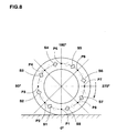
- the radial strain ⁇ z becomes about 0.2 % or less, namely, almost zero, even if the vertical load Fz is varied from zero to the normal tire load under the normally inflated state.
- At least one secondary strain sensor S is disposed in the vicinity X of the inflection point IP where the radial strain ⁇ z becomes 0.2 % or less as explained above. More specifically, the center of the sensor S is positioned at a radial distance of 4 mm or less from the inflection point IP. Since it is preferable that a plurality of secondary sensors s are arranged equiangularly around the tire rotational axis at the same radial height, eight secondary sensors S are used as shown in Fig.10 .
- the protrusion 14 can be used as so called rim protector. In this example, therefore, the protrusion 14 is formed on only the sidewall portion 3o intended to be positioned on the outside of the vehicle.
- the protrusion 14 in order to use the protrusion 14 as a rim protector, in the meridian section of the tire under the normally inflated state, the protrusion 14 has to protrude axially outwardly beyond the flange of the wheel rim, and in this example, the protrusion 14 is provided with an almost trapezoidal cross sectional shape comprising a radially inner oblique side 14a, a radially outer oblique side 14b and a axially outer side 14c extending between the axially outer ends of the sides 14a and 14b.
- the radially inner and outer oblique sides 14a and 14b are each convexly curved.
- the above-mentioned concave part 15B is formed by the outer oblique line 14b.
Landscapes
- Physics & Mathematics (AREA)
- General Physics & Mathematics (AREA)
- Engineering & Computer Science (AREA)
- Mechanical Engineering (AREA)
- Force Measurement Appropriate To Specific Purposes (AREA)
- Tires In General (AREA)
- Measuring Fluid Pressure (AREA)
Applications Claiming Priority (2)
| Application Number | Priority Date | Filing Date | Title |
|---|---|---|---|
| JP2007100833A JP5027549B2 (ja) | 2007-04-06 | 2007-04-06 | 空気入りタイヤ、及びそれに作用する力の検出方法 |
| JP2007100835A JP5149531B2 (ja) | 2007-04-06 | 2007-04-06 | タイヤの空気圧低下検出方法 |
Publications (3)
| Publication Number | Publication Date |
|---|---|
| EP1978345A2 true EP1978345A2 (de) | 2008-10-08 |
| EP1978345A3 EP1978345A3 (de) | 2010-08-25 |
| EP1978345B1 EP1978345B1 (de) | 2014-05-07 |
Family
ID=39590721
Family Applications (1)
| Application Number | Title | Priority Date | Filing Date |
|---|---|---|---|
| EP08004716.0A Not-in-force EP1978345B1 (de) | 2007-04-06 | 2008-03-13 | Verfahren zur Schätzung der Größe einer Kraft, die auf einen rollenden Reifen einwirkt |
Country Status (3)
| Country | Link |
|---|---|
| US (1) | US7707876B2 (de) |
| EP (1) | EP1978345B1 (de) |
| CN (1) | CN102358117B (de) |
Cited By (8)
| Publication number | Priority date | Publication date | Assignee | Title |
|---|---|---|---|---|
| EP2186657A4 (de) * | 2007-08-21 | 2013-07-03 | Sumitomo Rubber Ind | Reifenwirkungskrafterfassungsverfahren und bei dem verfahren verwendeter luftreifen |
| EP3059571A3 (de) * | 2015-02-19 | 2016-12-07 | VÚKV a.s. | System zur messung der krafteinwirkung am kontakt zwischen dem rad eines schienenfahrzeugs und der schiene, dessen kalibrierungsverfahren und kalibrierungsrahmen |
| WO2018224194A1 (de) * | 2017-06-07 | 2018-12-13 | Continental Reifen Deutschland Gmbh | Fahrzeugreifen |
| IT201800004925A1 (it) * | 2018-04-27 | 2019-10-27 | Pneumatico provvisto di un transponder | |
| CN111376660A (zh) * | 2018-12-26 | 2020-07-07 | 通伊欧轮胎株式会社 | 轮胎及轮胎的制造方法 |
| CN116147809A (zh) * | 2022-12-16 | 2023-05-23 | 上海核工程研究设计院股份有限公司 | 一种基于载荷应变关系的压力管道的载荷测量方法 |
| EP4706998A1 (de) * | 2024-08-29 | 2026-03-11 | The Goodyear Tire & Rubber Company | Reifen, verfahren und system mit einem sensor an einem felgenflanschübergangsbereich eines reifens durch hohlraumbildung |
| EP4706996A1 (de) * | 2024-08-29 | 2026-03-11 | The Goodyear Tire & Rubber Company | Reifen, verfahren und system mit einem sensor an einem felgenflanschübergangsbereich eines reifens durch hohlraumbildung |
Families Citing this family (13)
| Publication number | Priority date | Publication date | Assignee | Title |
|---|---|---|---|---|
| FR2891770B1 (fr) | 2005-10-06 | 2007-12-07 | Michelin Soc Tech | Procede et dispositif de mesure de pression de gonflage d'un pneumatique au moyen d'un capteur de contrainte |
| GB0601865D0 (en) * | 2006-01-30 | 2006-03-08 | Bp Chem Int Ltd | Process |
| FR2924518B1 (fr) * | 2007-11-30 | 2009-11-20 | Michelin Soc Tech | Dispositif de localisation de la position droite et gauche d'un ensemble pneumatique et roue d'un vehicule |
| US8447578B2 (en) * | 2008-05-07 | 2013-05-21 | Bridgestone Americas Tire Operations, Llc | Method of designing a tire having a target residual aligning torque |
| DE102008046269B3 (de) * | 2008-09-08 | 2009-12-24 | Continental Automotive Gmbh | Verfahren und Meßsystem zur Bestimmung einer Radlast |
| FR2962689B1 (fr) * | 2010-07-13 | 2014-01-31 | Michelin Soc Tech | Procede d'estimation de la charge dynamique portee par un pneumatique d'un vehicule. |
| US9815343B1 (en) * | 2014-06-06 | 2017-11-14 | Iowa State University Research Foundation, Inc. | Tire sensing method for enhanced safety and controllability of vehicles |
| US10639948B2 (en) | 2014-12-30 | 2020-05-05 | Bridgestone Americas Tire Operations, Llc | Assembly for attaching an electronics package to a tire |
| JP7272773B2 (ja) * | 2018-10-03 | 2023-05-12 | Toyo Tire株式会社 | タイヤ |
| JP6594509B1 (ja) * | 2018-10-03 | 2019-10-23 | Toyo Tire株式会社 | タイヤおよびタイヤの製造方法 |
| JP6790142B2 (ja) * | 2019-01-31 | 2020-11-25 | Toyo Tire株式会社 | タイヤ力推定システムおよびタイヤ力推定方法 |
| US11774301B2 (en) | 2020-06-16 | 2023-10-03 | The Goodyear Tire & Rubber Company | Tire load estimation system and method |
| CN119958882B (zh) * | 2025-01-13 | 2025-11-14 | 江西五十铃汽车有限公司 | 轮胎磨损测量方法、系统、可读存储介质及计算机 |
Citations (4)
| Publication number | Priority date | Publication date | Assignee | Title |
|---|---|---|---|---|
| US6491076B1 (en) | 2000-06-13 | 2002-12-10 | The Goodyear Tire & Rubber Company | Triangular bead configuration for pneumatic tire with extended load carrying capacity |
| US20040158441A1 (en) | 2001-08-06 | 2004-08-12 | David Bertrand | Method of determining characteristics of a tyre from stresses |
| US20050103100A1 (en) | 2003-10-27 | 2005-05-19 | Sumitomo Rubber Industries, Ltd. | System and method for determining tire force |
| JP2006038554A (ja) | 2004-07-26 | 2006-02-09 | Sumitomo Electric Ind Ltd | タイヤに作用する力の検出装置 |
Family Cites Families (4)
| Publication number | Priority date | Publication date | Assignee | Title |
|---|---|---|---|---|
| DE19522269A1 (de) * | 1995-06-20 | 1997-01-02 | Continental Ag | Vorrichtung zum Ermitteln und Aufaddieren der Umdrehungen eines Reifens |
| US6756892B2 (en) * | 1997-01-15 | 2004-06-29 | Algonquin Scientific, Llc | Tire pressure sensing system |
| US6523408B1 (en) * | 2000-07-27 | 2003-02-25 | Hunter Engineering Company | Wheel balancer system with improved matching capabilities |
| JP4165380B2 (ja) * | 2003-01-31 | 2008-10-15 | 株式会社豊田中央研究所 | 車両制御方法及び車両制御装置 |
-
2008
- 2008-03-13 EP EP08004716.0A patent/EP1978345B1/de not_active Not-in-force
- 2008-03-25 US US12/076,931 patent/US7707876B2/en not_active Expired - Fee Related
- 2008-04-03 CN CN2011102519508A patent/CN102358117B/zh not_active Expired - Fee Related
Patent Citations (5)
| Publication number | Priority date | Publication date | Assignee | Title |
|---|---|---|---|---|
| US6491076B1 (en) | 2000-06-13 | 2002-12-10 | The Goodyear Tire & Rubber Company | Triangular bead configuration for pneumatic tire with extended load carrying capacity |
| US20040158441A1 (en) | 2001-08-06 | 2004-08-12 | David Bertrand | Method of determining characteristics of a tyre from stresses |
| US20050103100A1 (en) | 2003-10-27 | 2005-05-19 | Sumitomo Rubber Industries, Ltd. | System and method for determining tire force |
| US7249498B2 (en) | 2003-10-27 | 2007-07-31 | Sumitomo Rubber Industries, Ltd. | System and method for determining tire force |
| JP2006038554A (ja) | 2004-07-26 | 2006-02-09 | Sumitomo Electric Ind Ltd | タイヤに作用する力の検出装置 |
Cited By (11)
| Publication number | Priority date | Publication date | Assignee | Title |
|---|---|---|---|---|
| EP2186657A4 (de) * | 2007-08-21 | 2013-07-03 | Sumitomo Rubber Ind | Reifenwirkungskrafterfassungsverfahren und bei dem verfahren verwendeter luftreifen |
| EP3059571A3 (de) * | 2015-02-19 | 2016-12-07 | VÚKV a.s. | System zur messung der krafteinwirkung am kontakt zwischen dem rad eines schienenfahrzeugs und der schiene, dessen kalibrierungsverfahren und kalibrierungsrahmen |
| WO2018224194A1 (de) * | 2017-06-07 | 2018-12-13 | Continental Reifen Deutschland Gmbh | Fahrzeugreifen |
| IT201800004925A1 (it) * | 2018-04-27 | 2019-10-27 | Pneumatico provvisto di un transponder | |
| WO2019207422A1 (en) * | 2018-04-27 | 2019-10-31 | Bridgestone Europe Nv/Sa | Pneumatic tyre equipped with a transponder |
| US11541703B2 (en) | 2018-04-27 | 2023-01-03 | Bridgestone Europe N.V./S.A. | Pneumatic tire equipped with a transponder |
| CN111376660A (zh) * | 2018-12-26 | 2020-07-07 | 通伊欧轮胎株式会社 | 轮胎及轮胎的制造方法 |
| CN111376660B (zh) * | 2018-12-26 | 2022-10-04 | 通伊欧轮胎株式会社 | 轮胎及轮胎的制造方法 |
| CN116147809A (zh) * | 2022-12-16 | 2023-05-23 | 上海核工程研究设计院股份有限公司 | 一种基于载荷应变关系的压力管道的载荷测量方法 |
| EP4706998A1 (de) * | 2024-08-29 | 2026-03-11 | The Goodyear Tire & Rubber Company | Reifen, verfahren und system mit einem sensor an einem felgenflanschübergangsbereich eines reifens durch hohlraumbildung |
| EP4706996A1 (de) * | 2024-08-29 | 2026-03-11 | The Goodyear Tire & Rubber Company | Reifen, verfahren und system mit einem sensor an einem felgenflanschübergangsbereich eines reifens durch hohlraumbildung |
Also Published As
| Publication number | Publication date |
|---|---|
| US20080245459A1 (en) | 2008-10-09 |
| CN102358117A (zh) | 2012-02-22 |
| CN102358117B (zh) | 2013-12-04 |
| US7707876B2 (en) | 2010-05-04 |
| EP1978345B1 (de) | 2014-05-07 |
| EP1978345A3 (de) | 2010-08-25 |
Similar Documents
| Publication | Publication Date | Title |
|---|---|---|
| EP1978345B1 (de) | Verfahren zur Schätzung der Größe einer Kraft, die auf einen rollenden Reifen einwirkt | |
| CN101281096B (zh) | 用于估算作用在滚动轮胎上的轮胎受力的方法 | |
| EP1487682B1 (de) | Reifenüberwachungssystem und -vorrichtung eines kraftfahrzeugs | |
| US10960714B2 (en) | Tire with printed shear sensors | |
| US7513144B2 (en) | Pneumatic tire with specifically arranged strain sensors | |
| US7668669B2 (en) | Method for estimating magnitude of back-and-forth-direction force exerted on tire | |
| EP3628479B1 (de) | Reifen mit gedruckten dehnungssensoren | |
| US20070251619A1 (en) | Tire provided with a sensor placed between the carcass ply and the inner liner | |
| US12214626B2 (en) | Tire wear state detection device using waveform data | |
| EP4015252B1 (de) | Fahrzeugreifensensorhaltesystem | |
| CN111405992B (zh) | 轮胎组装体和轮胎变形状态判定系统 | |
| JP4268363B2 (ja) | 空気入りタイヤ及びタイヤ変形検出方法 | |
| JP6027305B2 (ja) | 空気入りタイヤ | |
| JP2009126460A (ja) | タイヤの故障検出方法 | |
| EP4477432B1 (de) | Reifen mit einem satz gedruckter sensoren | |
| US20260061784A1 (en) | Systems and methods for integrating sensors into rim flange transition area of a tire during process of manufacture | |
| CN119142076A (zh) | 带有一组打印传感器的轮胎 | |
| JP2008256607A (ja) | タイヤの空気圧低下検出方法 |
Legal Events
| Date | Code | Title | Description |
|---|---|---|---|
| PUAI | Public reference made under article 153(3) epc to a published international application that has entered the european phase |
Free format text: ORIGINAL CODE: 0009012 |
|
| AK | Designated contracting states |
Kind code of ref document: A2 Designated state(s): AT BE BG CH CY CZ DE DK EE ES FI FR GB GR HR HU IE IS IT LI LT LU LV MC MT NL NO PL PT RO SE SI SK TR |
|
| AX | Request for extension of the european patent |
Extension state: AL BA MK RS |
|
| PUAL | Search report despatched |
Free format text: ORIGINAL CODE: 0009013 |
|
| AK | Designated contracting states |
Kind code of ref document: A3 Designated state(s): AT BE BG CH CY CZ DE DK EE ES FI FR GB GR HR HU IE IS IT LI LT LU LV MC MT NL NO PL PT RO SE SI SK TR |
|
| AX | Request for extension of the european patent |
Extension state: AL BA MK RS |
|
| RIC1 | Information provided on ipc code assigned before grant |
Ipc: G01L 5/20 20060101ALI20100720BHEP Ipc: G01L 5/16 20060101AFI20080716BHEP |
|
| 17P | Request for examination filed |
Effective date: 20110119 |
|
| AKX | Designation fees paid |
Designated state(s): DE FR IT |
|
| RIC1 | Information provided on ipc code assigned before grant |
Ipc: G01L 5/20 20060101ALI20110808BHEP Ipc: G01L 5/16 20060101AFI20110808BHEP |
|
| 17Q | First examination report despatched |
Effective date: 20120724 |
|
| REG | Reference to a national code |
Ref country code: DE Ref legal event code: R079 Ref document number: 602008031972 Country of ref document: DE Free format text: PREVIOUS MAIN CLASS: G01L0005160000 Ipc: B60C0019000000 |
|
| RIC1 | Information provided on ipc code assigned before grant |
Ipc: B60C 19/00 20060101AFI20130527BHEP Ipc: G01L 5/16 20060101ALI20130527BHEP Ipc: G01L 5/20 20060101ALI20130527BHEP |
|
| GRAP | Despatch of communication of intention to grant a patent |
Free format text: ORIGINAL CODE: EPIDOSNIGR1 |
|
| INTG | Intention to grant announced |
Effective date: 20131009 |
|
| GRAS | Grant fee paid |
Free format text: ORIGINAL CODE: EPIDOSNIGR3 |
|
| GRAA | (expected) grant |
Free format text: ORIGINAL CODE: 0009210 |
|
| AK | Designated contracting states |
Kind code of ref document: B1 Designated state(s): DE FR IT |
|
| REG | Reference to a national code |
Ref country code: DE Ref legal event code: R096 Ref document number: 602008031972 Country of ref document: DE Effective date: 20140618 |
|
| REG | Reference to a national code |
Ref country code: DE Ref legal event code: R097 Ref document number: 602008031972 Country of ref document: DE |
|
| PLBE | No opposition filed within time limit |
Free format text: ORIGINAL CODE: 0009261 |
|
| STAA | Information on the status of an ep patent application or granted ep patent |
Free format text: STATUS: NO OPPOSITION FILED WITHIN TIME LIMIT |
|
| 26N | No opposition filed |
Effective date: 20150210 |
|
| REG | Reference to a national code |
Ref country code: DE Ref legal event code: R097 Ref document number: 602008031972 Country of ref document: DE Effective date: 20150210 |
|
| REG | Reference to a national code |
Ref country code: DE Ref legal event code: R119 Ref document number: 602008031972 Country of ref document: DE |
|
| PG25 | Lapsed in a contracting state [announced via postgrant information from national office to epo] |
Ref country code: IT Free format text: LAPSE BECAUSE OF NON-PAYMENT OF DUE FEES Effective date: 20150313 |
|
| REG | Reference to a national code |
Ref country code: FR Ref legal event code: ST Effective date: 20151130 |
|
| PG25 | Lapsed in a contracting state [announced via postgrant information from national office to epo] |
Ref country code: DE Free format text: LAPSE BECAUSE OF NON-PAYMENT OF DUE FEES Effective date: 20151001 |
|
| PG25 | Lapsed in a contracting state [announced via postgrant information from national office to epo] |
Ref country code: FR Free format text: LAPSE BECAUSE OF NON-PAYMENT OF DUE FEES Effective date: 20150331 |