EP1978313A2 - Solar array - Google Patents
Solar array Download PDFInfo
- Publication number
- EP1978313A2 EP1978313A2 EP08005376A EP08005376A EP1978313A2 EP 1978313 A2 EP1978313 A2 EP 1978313A2 EP 08005376 A EP08005376 A EP 08005376A EP 08005376 A EP08005376 A EP 08005376A EP 1978313 A2 EP1978313 A2 EP 1978313A2
- Authority
- EP
- European Patent Office
- Prior art keywords
- solar
- module
- units
- module units
- adjacent
- Prior art date
- Legal status (The legal status is an assumption and is not a legal conclusion. Google has not performed a legal analysis and makes no representation as to the accuracy of the status listed.)
- Withdrawn
Links
- 238000000034 method Methods 0.000 claims abstract description 5
- 230000001154 acute effect Effects 0.000 claims description 2
- 238000009434 installation Methods 0.000 claims 2
- 241001494479 Pecora Species 0.000 description 1
- 230000015572 biosynthetic process Effects 0.000 description 1
- 230000001419 dependent effect Effects 0.000 description 1
- 238000005755 formation reaction Methods 0.000 description 1
- 238000009304 pastoral farming Methods 0.000 description 1
Images


Classifications
-
- H—ELECTRICITY
- H02—GENERATION; CONVERSION OR DISTRIBUTION OF ELECTRIC POWER
- H02S—GENERATION OF ELECTRIC POWER BY CONVERSION OF INFRARED RADIATION, VISIBLE LIGHT OR ULTRAVIOLET LIGHT, e.g. USING PHOTOVOLTAIC [PV] MODULES
- H02S20/00—Supporting structures for PV modules
- H02S20/10—Supporting structures directly fixed to the ground
-
- F—MECHANICAL ENGINEERING; LIGHTING; HEATING; WEAPONS; BLASTING
- F24—HEATING; RANGES; VENTILATING
- F24S—SOLAR HEAT COLLECTORS; SOLAR HEAT SYSTEMS
- F24S30/00—Arrangements for moving or orienting solar heat collector modules
- F24S30/40—Arrangements for moving or orienting solar heat collector modules for rotary movement
- F24S30/42—Arrangements for moving or orienting solar heat collector modules for rotary movement with only one rotation axis
- F24S30/422—Vertical axis
-
- H—ELECTRICITY
- H02—GENERATION; CONVERSION OR DISTRIBUTION OF ELECTRIC POWER
- H02S—GENERATION OF ELECTRIC POWER BY CONVERSION OF INFRARED RADIATION, VISIBLE LIGHT OR ULTRAVIOLET LIGHT, e.g. USING PHOTOVOLTAIC [PV] MODULES
- H02S20/00—Supporting structures for PV modules
- H02S20/20—Supporting structures directly fixed to an immovable object
- H02S20/22—Supporting structures directly fixed to an immovable object specially adapted for buildings
- H02S20/23—Supporting structures directly fixed to an immovable object specially adapted for buildings specially adapted for roof structures
-
- H—ELECTRICITY
- H02—GENERATION; CONVERSION OR DISTRIBUTION OF ELECTRIC POWER
- H02S—GENERATION OF ELECTRIC POWER BY CONVERSION OF INFRARED RADIATION, VISIBLE LIGHT OR ULTRAVIOLET LIGHT, e.g. USING PHOTOVOLTAIC [PV] MODULES
- H02S20/00—Supporting structures for PV modules
- H02S20/30—Supporting structures being movable or adjustable, e.g. for angle adjustment
-
- F—MECHANICAL ENGINEERING; LIGHTING; HEATING; WEAPONS; BLASTING
- F24—HEATING; RANGES; VENTILATING
- F24S—SOLAR HEAT COLLECTORS; SOLAR HEAT SYSTEMS
- F24S20/00—Solar heat collectors specially adapted for particular uses or environments
- F24S2020/10—Solar modules layout; Modular arrangements
-
- F—MECHANICAL ENGINEERING; LIGHTING; HEATING; WEAPONS; BLASTING
- F24—HEATING; RANGES; VENTILATING
- F24S—SOLAR HEAT COLLECTORS; SOLAR HEAT SYSTEMS
- F24S20/00—Solar heat collectors specially adapted for particular uses or environments
- F24S2020/10—Solar modules layout; Modular arrangements
- F24S2020/16—Preventing shading effects
-
- F—MECHANICAL ENGINEERING; LIGHTING; HEATING; WEAPONS; BLASTING
- F24—HEATING; RANGES; VENTILATING
- F24S—SOLAR HEAT COLLECTORS; SOLAR HEAT SYSTEMS
- F24S30/00—Arrangements for moving or orienting solar heat collector modules
- F24S2030/10—Special components
- F24S2030/13—Transmissions
- F24S2030/136—Transmissions for moving several solar collectors by common transmission elements
-
- Y—GENERAL TAGGING OF NEW TECHNOLOGICAL DEVELOPMENTS; GENERAL TAGGING OF CROSS-SECTIONAL TECHNOLOGIES SPANNING OVER SEVERAL SECTIONS OF THE IPC; TECHNICAL SUBJECTS COVERED BY FORMER USPC CROSS-REFERENCE ART COLLECTIONS [XRACs] AND DIGESTS
- Y02—TECHNOLOGIES OR APPLICATIONS FOR MITIGATION OR ADAPTATION AGAINST CLIMATE CHANGE
- Y02B—CLIMATE CHANGE MITIGATION TECHNOLOGIES RELATED TO BUILDINGS, e.g. HOUSING, HOUSE APPLIANCES OR RELATED END-USER APPLICATIONS
- Y02B10/00—Integration of renewable energy sources in buildings
- Y02B10/10—Photovoltaic [PV]
-
- Y—GENERAL TAGGING OF NEW TECHNOLOGICAL DEVELOPMENTS; GENERAL TAGGING OF CROSS-SECTIONAL TECHNOLOGIES SPANNING OVER SEVERAL SECTIONS OF THE IPC; TECHNICAL SUBJECTS COVERED BY FORMER USPC CROSS-REFERENCE ART COLLECTIONS [XRACs] AND DIGESTS
- Y02—TECHNOLOGIES OR APPLICATIONS FOR MITIGATION OR ADAPTATION AGAINST CLIMATE CHANGE
- Y02E—REDUCTION OF GREENHOUSE GAS [GHG] EMISSIONS, RELATED TO ENERGY GENERATION, TRANSMISSION OR DISTRIBUTION
- Y02E10/00—Energy generation through renewable energy sources
- Y02E10/40—Solar thermal energy, e.g. solar towers
- Y02E10/47—Mountings or tracking
-
- Y—GENERAL TAGGING OF NEW TECHNOLOGICAL DEVELOPMENTS; GENERAL TAGGING OF CROSS-SECTIONAL TECHNOLOGIES SPANNING OVER SEVERAL SECTIONS OF THE IPC; TECHNICAL SUBJECTS COVERED BY FORMER USPC CROSS-REFERENCE ART COLLECTIONS [XRACs] AND DIGESTS
- Y02—TECHNOLOGIES OR APPLICATIONS FOR MITIGATION OR ADAPTATION AGAINST CLIMATE CHANGE
- Y02E—REDUCTION OF GREENHOUSE GAS [GHG] EMISSIONS, RELATED TO ENERGY GENERATION, TRANSMISSION OR DISTRIBUTION
- Y02E10/00—Energy generation through renewable energy sources
- Y02E10/50—Photovoltaic [PV] energy
Definitions
- the present invention relates to a solar system with a plurality of modular units, which generally have a plurality of solar modules.
- Solar systems have long been known from the prior art.
- the solar modules are installed on roofs and open spaces.
- roof systems for example, a southward orientation is preferred.
- Most of the solar modules are aligned at a certain angle to the ground (so-called angle of attack).
- the solar modules are arranged in rows next to each other to solar module units.
- the present invention has for its object to provide a solar system available, which overcomes the disadvantages of the prior art.
- Their particular task is to provide a solar system available, which works with minimum space requirements even on uneven terrain with high energy efficiency.
- a solar system comprising a plurality of elongated modular units, each having at least one solar module, wherein the individual module units are trackable to the sun's course. Due to the elongated shape of the modular units of the solar system according to the invention, which are individually tracking the course of the sun, it is possible to place in a very small space a plurality of modular units, which do not or only slightly shadow each other.
- the modular units are substantially rectangular. Due to the rectangular shape, a particularly space-saving arrangement of the module units of the solar system according to the invention is possible.
- the modular units of the solar system according to the invention generally have a ratio of width to length in the range of about 1: 1.5 to 1:10, preferably about 1: 2 to 1: 5, particularly preferably about 1: 3, on.
- the modular units are arranged in at least two, preferably a plurality of substantially parallel rows, each formed by a straight line on which the centers or pivot points of the individual module elements lie substantially, wherein the individual module units of two adjacent rows are preferably arranged offset, in particular in such a way that the centers of two adjacent modular units of a series with a center of a modular unit of an adjacent row form a substantially isosceles triangle.
- the length of a modular unit of a solar system according to the invention is smaller, preferably by about 10% to 20% less than the distance between the centers of two adjacent modular units of a row.
- the distance between the centers of two adjacent module units of a row approximately corresponds to the distance between two adjacent rows.
- the individual module elements of the sun are substantially uniformly trackable and are preferably coupled together for this purpose. This arrangement ensures that not every module element has to be individually adapted to the solar history, but that a central control is possible.
- the modular units of the solar system according to the invention are set up so that they with an horizontal (eg with a flat bottom or bottom) an angle of about 20 ° to about 80 °, preferably from about 30 ° to about 45 °, especially preferably from about 35 ° to 40 °. In central European locations, an angle of about 38 ° is preferred. With this angle of attack the most effective use of the sun can be achieved. When tracking is not only a single-axis tracking possible. It is certainly also a biaxial tracking conceivable, which is adjustable mechanically or automatically. As a result, the angle of attack is adaptable to different times of the day.
- a height of 2.5 m is not exceeded in the solar system according to the invention. This achieves high resistance to wind loads.
- a ground clearance of about 1 m is usually complied with.
- livestock farming e.g., sheep husbandry
- sheep husbandry is possible on the surface of the solar plant, for example.
- adjacent solar modules of a modular unit of the invention- ⁇ en solar system are arranged at a distance from each other.
- Such an arrangement also contributes to the wind stability of the modular units, since here the wind and suction loads can be taken much cheaper and air turbulence arise.
- the modular unit length can also be advantageously filled.
- the present invention further relates to a solar module unit, which is characterized in that it is elongated and the sun is trackable.
- a solar module unit is ideal for mounting a solar system according to one of claims 1-10.
- the solar module unit according to the invention is substantially rectangular.
- the solar module unit according to the invention preferably has a ratio of width to length in the range from about 1: 1.5 to 1:10, preferably from about 1: 2 to 1: 5, particularly preferably from about 1: 3.
- the present invention furthermore relates to a method for arranging solar module units, in particular solar module units according to the invention, for installing a solar system, in particular a solar system according to the invention, comprising the following working step: Positioning the axes of rotation of the individual module units in at least two substantially parallel rows, wherein the axes of rotation of the modular units of two adjacent rows are arranged offset such that two adjacent axes of rotation of a row with a rotation axis of a nearest modular unit form the other row a substantially isosceles triangle, wherein the distances of the module elements are mutually selected so that a touching of the modular units when rotating about the axes of rotation is excluded, wherein the modular units are positioned so that they are at an acute angle, preferably an angle of about 35 ° - 42 ° include, wherein the distance of the rows is chosen so that a mutual shading of the solar modules during the day is substantially avoided, and wherein the individual module units are substantially evenly tracked the course of the sun.
- a solar system can be installed, which works most effective with the greatest possible space utilization.
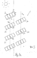
- FIG. 1 a shows a section of a solar system 1 according to the invention in the morning.
- the solar system 1 has a plurality of modular units 2, which each have four solar modules 3.
- the modular units 2 have a rectangular shape.
- the modular units 2 are placed with a slope to the ground and close with the ground an angle of about 38 °.
- the module units are positioned so that their solar modules face the sun. This arrangement is in the FIGS. 1a-f not recognizable. This is on the FIG. 2 directed.
- the module units 2 are individually trackable to the sun.
- each module unit 2 is assigned a tracking device. These individual tracking devices can, for example, by means of a motor, put the module units 2 in a rotational movement and thus track the sun.
- These NachS. 1a-f can be coupled together, so that a coordinated tracking movement of the individual module units is possible.
- the modular units 2 have a ratio of width b to length 1 of about 1: 3.
- the modular units 2 are arranged in a plurality of substantially parallel rows (in the present case, only two such rows R 1 and R 2 are shown).
- the individual rows R (dashed lines in the figures) are each defined by a straight line on which the centers or pivot points of the individual module units 2 lie.
- the individual module units 2 of two adjacent rows R are staggered, in such a way that the centers of two adjacent module units 2 of a row with a center of a module unit of an adjacent row form a substantially isosceles triangle.
- To form in the FIG. 1a the centers D1 and D2 of the row R 1 with the center D3 of the series R 2 an isosceles triangle.
- the length of a module unit 2 is about 20% less than the distance between the centers of two adjacent modular units 2 of a row. As a result, touching the individual rows of modules during the tracking movement is prevented.
- the distance between the centers of two adjacent module units 2 of one row approximately corresponds to the distance between two adjacent rows.
- the modular units 2 of two adjacent rows in turn form parallel rows of juxtaposed rows of modules.
- the module units 2a and 2b, together with other module units, not shown here form a module unit row.
- Parallel to this row of modular units is a row of modular units parallel to this row consisting of module units 2c and 2d.
- the individual module units of a modular unit row are arranged at a small distance from each other, which is sufficient, however, that the module units do not touch during the rotary movement.
- FIG. 1b shows Solaranlade 1 in the early morning.
- the individual module units 2 are now arranged such that they form parallel modular unit rows with further module units, not shown here, of further rows.
- the distance of the modular units 2 within such modular unit rows is greater at this position than at the position in FIG. 1a , wherein this distance is greater than the length of the individual module units 2 .:
- Both in the position of FIG. 1 a as well as in the FIG. 1b is the distance between the successive module units (eg module unit 2a and module unit 2c) is so large that a mutual shading as good as not takes place.
- FIG. 3c shows the solar system 1 in comparison to FIG. 1b about one to two hours later.
- new rows of modular units 2 have again formed.
- the module units 2a and 2d (together with other module units, not shown here) now form a module unit row.
- Figure 1d shows the solar system 1 after compared to Figure 1c again a certain time has elapsed (late morning).
- module units 2e and 2b now lie in a module unit row.
- the modular units eg module unit 2b and 2a or 2d and 2c
- arranged immediately one behind the other are again far enough apart to prevent mutual shading.
- the Figure 1e shows the solar system 1 at lunchtime.
- the modular units 2 of a row eg R 1 or R 2
- the module units 2a and 2c or 2b and 2d each lie in a modular unit row.
- FIG. 1f shows the solar system 1 already in the evening hours. Order from the arrangement in FIG. 1a (Morning sun) to the arrangement in FIG. 1f (Evening sun), a tracking of the modular units 2 of over 200 ° was required. Between the arrangement in Figure 1e and the arrangement in FIG. 1f is half a day. Within this half day, it has of course come to further modular unit series - formations. When arranged in FIG. 1f For example, module units 2e and 2b and 2a and 2d now form modular unit rows.
- the modular units of FIGS. 1a to 1f preferably have a length of 4.5 m and a width of 1.6 m.
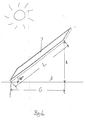
- FIG. 2 shows a solar module 3 of a module unit 2.
- the solar module 3 is arranged at a certain angle. This angle of attack in the present case is 38 °. By the angle of attack results over the length L of the solar module 4, a corresponding height h starting from a horizontal base line Z.
- the length of the base area under the solar module 3 in the plan view is denoted by G. From the length L of the solar module and the angle of attack results in the so-called shading factor.
- This shading factor corresponds to the distance between two successive solar modules or module units, the is to be observed in order to avoid just a mutual shading. This shading factor is regionally different.
- the height h of the solar module must be multiplied by the shading factor and the basic length G added to the result. If the height h corresponds, for example, to 1 m and the shading factor is 4 m and the basic length G is 1.3 m, for example, the distance between two rows (eg R 1 and R 2 ) is 5.3 m. This distance ensures that the modular element rows forming in the course of the day (not to be confused with the rows of pivot points, eg R 1 and R 2 ) do not mutually shadow each other.
Abstract
Description
Die vorliegende Erfindung betrifft eine Solaranlage mit einer Mehrzahl von Moduleinheiten, welche in der Regel mehrere Solarmodule aufweisen.The present invention relates to a solar system with a plurality of modular units, which generally have a plurality of solar modules.
Aus dem Stand der Technik sind Solaranlagen seit langem bekannt. Bei den meisten Solaranlagen werden die Solarmodule auf Dächern und Freiflächen installiert. Bei Dachanlagen ist beispielsweise eine Ausrichtung gegen Süden bevorzugt. Meist sind die Solarmodule in einem bestimmten Winkel zum Boden ausgerichtet (so genannter Anstellwinkel). Häufig werden die Solarmodule in Reihen nebeneinander zu Solarmoduleinheiten angeordnet.Solar systems have long been known from the prior art. For most solar systems, the solar modules are installed on roofs and open spaces. For roof systems, for example, a southward orientation is preferred. Most of the solar modules are aligned at a certain angle to the ground (so-called angle of attack). Frequently, the solar modules are arranged in rows next to each other to solar module units.
Der Nachteil dieser Solaranlagen besteht beispielsweise darin, dass es zu einer Verschattung der hintereinander liegenden Modulreihen kommt, falls diese nicht in ausreichendem Abstand voneinander angeordnet sind.The disadvantage of these solar systems, for example, is that it comes to a shading of the successive module rows, if they are not arranged at a sufficient distance from each other.
Ferner sind Solaranlagen mit annähernd quadratisch ausgebildeten Moduleinheiten bekannt, die dem Sonnenverlauf nachführbar sind und hierzu häufig auf ein Antriebselement gesetzt werden. Dadurch können die Solarmoduleinheiten zum Teil zweiachsig der Sonne nachgeführt werden. Dies bringt in mitteleuropäischer Lage einen Mehrertrag an Energie von ca. 30 %, in südlichen Ländern ca. 40 %. Durch das Nachführen der Solarmoduleinheiten der Sonne müssen weiträumige Abstände kreisförmig um die Solarmoduleinheiten eingehalten werden, um gegenseitige Verschattungen zu verhindern. Hierfür ist ein großer Platzbedarf von Nöten. Die einzelnen Solarmoduleinheiten sind weit voneinander entfernt angeordnet.
Neben dem großen Platzbedarf dieser Anlagen sind diese auch sehr windanfällig, da die einzelnen Solarmoduleinheiten ungeschützt und frei im Gelände stehen.Furthermore, solar systems with approximately square-shaped modular units are known, which are trackable to the Sun and this often be placed on a drive element. As a result, the solar module units can sometimes be tracked biaxially to the sun. This brings in central European situation a surplus of energy of approx. 30%, in southern countries approx. 40%. By tracking the solar module units of the sun, spacious distances must be kept circular around the solar module units in order to prevent mutual shading. This requires a lot of space. The individual solar module units are arranged far apart.
In addition to the large footprint of these systems, these are also very susceptible to wind, as the individual solar module units are unprotected and free off-road.
Eine andere bekannte Variante der Nachführung von Solarmodulen der Sonne ist die Anordnung der Modulreihen auf großen Drehtellern. Diese werden in einem Durchmesser von bis zu 30 Metern auf eine Gleisbahn gestellt. Der Aufwand und somit die Kosten liegen für solche Anlagen sehr hoch. Allein der Aufwand, das Gelände flächig einzuebnen, um diesen Drehteller auf ein stabiles Fundament zu setzen, ist groß. Die runde Form führt ebenfalls wieder zu einer ungünstigen Flächenausnutzung.Another known variant of the tracking of solar modules of the sun is the arrangement of the module rows on large turntables. These are placed on a track in a diameter of up to 30 meters. The effort and thus the costs are very high for such systems. But the effort to planarize the terrain area to put this turntable on a stable foundation is great. The round shape also leads again to an unfavorable area utilization.
Der vorliegenden Erfindung liegt die Aufgabe zugrunde, eine Solaranlage zur Verfügung zu stellen, welche die Nachteile des Standes der Technik überwindet. Ihr liegt insbesondere die Aufgabe zugrunde, eine Solaranlage zur Verfügung zu stellen, welche bei geringstem Platzbedarf auch bei unebenem Gelände mit hoher Energieeffizienz arbeitet.The present invention has for its object to provide a solar system available, which overcomes the disadvantages of the prior art. Their particular task is to provide a solar system available, which works with minimum space requirements even on uneven terrain with high energy efficiency.
Diese Aufgabe wird durch eine Solaranlage gelöst, umfassend eine Mehrzahl von länglich ausgebildeten Moduleinheiten mit jeweils mindestens einem Solarmodul, wobei die einzelnen Moduleinheiten dem Sonnenverlauf nachführbar sind.
Durch die längliche Form der Moduleinheiten der erfindungsgemäßen Solaranlage, welche einzeln dem Sonnenverlauf nachführbar sind, ist es möglich, auf sehr geringem Raum eine Vielzahl von Moduleinheiten zu platzieren, welche sich nicht oder nur geringfügig gegenseitig verschatten.This object is achieved by a solar system, comprising a plurality of elongated modular units, each having at least one solar module, wherein the individual module units are trackable to the sun's course.
Due to the elongated shape of the modular units of the solar system according to the invention, which are individually tracking the course of the sun, it is possible to place in a very small space a plurality of modular units, which do not or only slightly shadow each other.
Bei einer besonders bevorzugten Ausführungsform der erfindungsgemäßen Solaranlage sind die Moduleinheiten im Wesentlichen rechteckig ausgebildet. Durch die rechteckige Form ist ein besonders Platz sparendes Anordnen der Moduleinheiten der erfindungsgemäßen Solaranlage möglich.In a particularly preferred embodiment of the solar system according to the invention, the modular units are substantially rectangular. Due to the rectangular shape, a particularly space-saving arrangement of the module units of the solar system according to the invention is possible.
Die Moduleinheiten der erfindungsgemäßen Solaranlage weisen in der Regel ein Verhältnis von Breite zu Länge im Bereich von ca. 1 : 1,5 bis 1 : 10, vorzugsweise ca. 1 : 2 bis 1 : 5, besonders bevorzugt von ca. 1 : 3, auf.The modular units of the solar system according to the invention generally have a ratio of width to length in the range of about 1: 1.5 to 1:10, preferably about 1: 2 to 1: 5, particularly preferably about 1: 3, on.
Bei einer besonders bevorzugten Ausführungsform der erfindungsgemäßen Solaranlage sind die Moduleinheiten in mindestens zwei, vorzugsweise mehreren, im Wesentlichen parallelen Reihen, jeweils gebildet durch eine Gerade, auf welcher die Mittelpunkte bzw. Drehpunkte der einzelnen Modulelement im Wesentlichen liegen, angeordnet, wobei die einzelnen Moduleinheiten zweier benachbarter Reihen vorzugsweise versetzt angeordnet sind, insbesondere in der Weise, dass die Mittelpunkte zweier benachbarter Moduleinheiten einer Reihe mit einem Mittelpunkt einer Moduleinheit einer benachbarten Reihe ein im Wesentlichen gleichschenkliges Dreieck bilden.
Durch diese Anordnung bilden sich im Tagesverlauf beim Nachführen der Moduleinheiten im Sonnenverlauf ständig neue, parallel angeordnete Moduleinheitsreihen (siehe hierzu auch
As a result of this arrangement, during the course of the day during the tracking of the module units in the course of the sun, new modular unit rows arranged in parallel are formed (see also FIG
Mit Vorteil ist die Länge einer Moduleinheit einer erfindungsgemäßen Solaranlage geringer, vorzugsweise um ca. 10 % bis 20 % geringer, als der Abstand zwischen den Mittelpunkten zweier benachbarter Moduleinheiten einer Reihe. Durch diese Anordnung wird ein gegenseitiges Berühren der Moduleinheiten bei der Sonnen-Nachführbewegung vermieden. Bei dieser Anordnung liegt der Platzbedarf je KW bei ca. 50% niedriger.Advantageously, the length of a modular unit of a solar system according to the invention is smaller, preferably by about 10% to 20% less than the distance between the centers of two adjacent modular units of a row. By this arrangement, a mutual contact of the module units is avoided in the solar tracking movement. In this arrangement, the space required per KW is about 50% lower.
Mit Vorteil entspricht der Abstand zwischen den Mittelpunkten zweier benachbarter Moduleinheiten einer Reihe in etwa dem Abstand zwischen zwei benachbarten Reihen.Advantageously, the distance between the centers of two adjacent module units of a row approximately corresponds to the distance between two adjacent rows.
Vorzugsweise sind die einzelnen Modulelemente der Sonne im Wesentlichen gleichmäßig nachführbar und sind zu diesem Zweck vorzugsweise miteinander gekoppelt. Durch diese Anordnung wird erreicht, dass nicht jedes Modulelement einzeln an den Sonnenverlauf angepasst werden muss, sondern dass eine zentrale Steuerung möglich ist.Preferably, the individual module elements of the sun are substantially uniformly trackable and are preferably coupled together for this purpose. This arrangement ensures that not every module element has to be individually adapted to the solar history, but that a central control is possible.
Vorzugsweise sind die Moduleinheiten der erfindungsgemäßen Solaranlage derart aufgestellt, dass sie mit einer Waagrechten (z.B. mit einem ebenen Boden oder Grund) einen Winkel von ca. 20° bis ca. 80°, vorzugsweise von ca. 30° bis ca. 45°, besonders bevorzugt von ca. 35° bis 40°, einschließen. In mitteleuropäischen Lagen ist ein Winkel von ca. 38° bevorzugt. Mit diesem Anstellwinkel ist die effektivste Sonnenausnutzung zu erreichen.
Bei der Nachführung ist nicht nur eine einachsige Nachführung möglich. Es ist durchaus auch eine zweiachsige Nachführung denkbar, welche mechanisch oder automatisch einstellbar ist. Dadurch ist der Anstellwinkel an unterschiedliche Tageszeiten anpassbar.Preferably, the modular units of the solar system according to the invention are set up so that they with an horizontal (eg with a flat bottom or bottom) an angle of about 20 ° to about 80 °, preferably from about 30 ° to about 45 °, especially preferably from about 35 ° to 40 °. In central European locations, an angle of about 38 ° is preferred. With this angle of attack the most effective use of the sun can be achieved.
When tracking is not only a single-axis tracking possible. It is certainly also a biaxial tracking conceivable, which is adjustable mechanically or automatically. As a result, the angle of attack is adaptable to different times of the day.
Mit Vorteil wird bei der erfindungsgemäßen Solaranlage eine Bauhöhe von 2,5 m nicht überschritten. Dadurch wird eine hohe Widerstandsfähigkeit bei Windbelastungen erreicht. Andererseits wird in der Regel eine Bodenfreiheit von ca. 1 m eingehalten. Dadurch ist beispielsweise Nutztierhaltung (z.B. Schafhaltung) auf der Fläche der Solaranlage möglich.Advantageously, a height of 2.5 m is not exceeded in the solar system according to the invention. This achieves high resistance to wind loads. On the other hand, a ground clearance of about 1 m is usually complied with. As a result, livestock farming (e.g., sheep husbandry) is possible on the surface of the solar plant, for example.
Mit Vorteil sind benachbarte Solarmodule einer Moduleinheit der erfindungsgemä-βen Solaranlage mit Abstand zueinander angeordnet. Eine derartige Anordnung trägt ebenfalls zur Windstabilität der Moduleinheiten bei, da hier die Wind- und Soglasten wesentlich günstiger aufgenommen werden können und Luftverwirbelungen entstehen. Dadurch lässt sich zudem die Moduleinheitslänge vorteilhaft ausfüllen.Advantageously, adjacent solar modules of a modular unit of the invention-βen solar system are arranged at a distance from each other. Such an arrangement also contributes to the wind stability of the modular units, since here the wind and suction loads can be taken much cheaper and air turbulence arise. As a result, the modular unit length can also be advantageously filled.
Die vorliegende Erfindung betrifft ferner eine Solarmoduleinheit, welche dadurch gekennzeichnet ist, dass sie länglich ausgebildet ist und der Sonne nachführbar ist. Eine derartige Solarmoduleinheit eignet sich hervorragend für die Montage einer Solaranlage nach einem der Ansprüche 1 - 10.The present invention further relates to a solar module unit, which is characterized in that it is elongated and the sun is trackable. Such a solar module unit is ideal for mounting a solar system according to one of claims 1-10.
Vorzugsweise ist die erfindungsgemäße Solarmoduleinheit im Wesentlichen rechteckig ausgebildet.Preferably, the solar module unit according to the invention is substantially rectangular.
Vorzugsweise weist die erfindungsgemäße Solarmoduleinheit ein Verhältnis von Breite zu Länge im Bereich von ca. 1 : 1,5 bis 1 : 10, vorzugsweise ca. 1 : 2 bis 1 : 5, besonders bevorzugt von ca. 1:3, auf.The solar module unit according to the invention preferably has a ratio of width to length in the range from about 1: 1.5 to 1:10, preferably from about 1: 2 to 1: 5, particularly preferably from about 1: 3.
Die vorliegende Erfindung betrifft ferner ein Verfahren zum Anordnen von Solarmoduleinheiten, insbesondere von erfindungsgemäßen Solarmoduleinheiten, zur Installierung einer Solaranlage, insbesondere einer erfindungsgemäßen Solaranlage, umfassend folgenden Arbeitsschritt:
Positionieren der Drehachsen der einzelnen Moduleinheiten in mindestens 2 im Wesentlichen parallele Reihen, wobei die Drehachsen der Moduleinheiten zweier benachbarter Reihen derart versetzt angeordnet werden, dass zwei benachbarte Drehachsen einer Reihe mit einer Drehachse einer nächstgelegenen Moduleinheit der anderen Reihe ein im Wesentlichen gleichschenkliges Dreieck bilden, wobei die Abstände der Modulelemente untereinander so gewählt werden, dass ein Berühren der Moduleinheiten beim Drehen um die Drehachsen ausgeschlossen ist, wobei die Moduleinheiten so aufgestellt werden, dass sie mit einer Waagrechten einen spitzen Winkel, vorzugsweise einen Winkel von ca. 35° - 42°, einschließen, wobei der Abstand der Reihen so gewählt wird, dass eine gegenseitige Verschattung der Solarmodule im Tagesverlauf im Wesentlichen vermieden wird, und wobei die einzelnen Moduleinheiten im Wesentlichen gleichmäßig dem Sonnenverlauf nachgeführt werden.The present invention furthermore relates to a method for arranging solar module units, in particular solar module units according to the invention, for installing a solar system, in particular a solar system according to the invention, comprising the following working step:
Positioning the axes of rotation of the individual module units in at least two substantially parallel rows, wherein the axes of rotation of the modular units of two adjacent rows are arranged offset such that two adjacent axes of rotation of a row with a rotation axis of a nearest modular unit form the other row a substantially isosceles triangle, wherein the distances of the module elements are mutually selected so that a touching of the modular units when rotating about the axes of rotation is excluded, wherein the modular units are positioned so that they are at an acute angle, preferably an angle of about 35 ° - 42 ° include, wherein the distance of the rows is chosen so that a mutual shading of the solar modules during the day is substantially avoided, and wherein the individual module units are substantially evenly tracked the course of the sun.
Durch das erfindungsgemäße Verfahren kann eine Solaranlage installiert werden, welche unter größtmöglichster Platzausnutzung höchst effektiv arbeitet.By the method according to the invention, a solar system can be installed, which works most effective with the greatest possible space utilization.
Weitere Merkmale der Erfindung ergeben sich aus der nachfolgenden Beschreibung von bevorzugten Ausführungsformen der Erfindung in Verbindung mit den Zeichnungen und den Unteransprüchen. Hierbei können die einzelnen Merkmale jeweils für sich allein oder in Kombination miteinander verwirklicht sein.Further features of the invention will become apparent from the following description of preferred embodiments of the invention in conjunction with the drawings and the dependent claims. In this case, the individual features can be implemented individually or in combination with each other.
In den Zeichnungen zeigen:
Figur 1 a-f:- einen Ausschnitt aus einer erfindungsgemäßen Solaranlage im Tagesverlauf;
- Figur 2:
- ein Solarmodul aus einer erfindungsgemäßen Moduleinheit.
- Figuren 1a - 1f
- zeigen einen Ausschnitt aus einer
erfindungsgemäßen Solaranlage 1 im Tagesverlauf.
- Figure 1 af:
- a section of a solar system according to the invention during the day;
- FIG. 2:
- a solar module of a modular unit according to the invention.
- FIGS. 1a-1f
- show a section of a
solar system 1 according to the invention during the day.
Die Moduleinheiten 2 sind mit einer Neigung zum Boden aufgestellt und schließen mit dem Boden einen Winkel von ca. 38° ein. Die Moduleinheiten sind dabei natürlich so positioniert, dass ihre Solarmodule der Sonne zugewandt sind. Diese Anordnung ist in den
Die Nachführeinrichtungen greifen bei den vorliegenden Moduleinheiten an deren Mittelpunkt (Drehpunkt D) an.The trackers attack at the present module units at the center (pivot point D).
Die Moduleinheiten 2 weisen ein Verhältnis von Breite b zu Länge 1 von ca. 1 : 3 auf. Die Moduleinheiten 2 sind in mehreren im Wesentlichen parallelen Reihen angeordnet (im vorliegenden Fall sind lediglich zwei solcher Reihen R1 und R2 abgebildet). Die einzelnen Reihen R (in den Abbildungen gestrichelt gezeichnet) werden jeweils durch eine Gerade definiert, auf welcher die Mittelpunkte bzw. Drehpunkte der einzelnen Moduleinheiten 2 liegen. Die einzelnen Moduleinheiten 2 zweier benachbarter Reihen R sind versetzt angeordnet, und zwar in der Weise, dass die Mittelpunkte zweier benachbarter Moduleinheiten 2 einer Reihe mit einem Mittelpunkt einer Moduleinheit einer benachbarten Reihe ein im Wesentlichen gleichschenkliges Dreieck bilden. So bilden in der
Die Länge einer Moduleinheit 2 ist um ca. 20 % geringer als der Abstand zwischen den Mittelpunkten zweier benachbarter Moduleinheiten 2 einer Reihe. Dadurch wird ein Berühren der einzelnen Modulreihen bei der Nachführbewegung verhindert.The length of a
Ferner entspricht der Abstand zwischen den Mittelpunkten zweier benachbarter Moduleinheiten 2 einer Reihe in etwa dem Abstand zwischen zwei benachbarten Reihen.Further, the distance between the centers of two
Zur Bestimmung des Abstandes zwischen zwei benachbarten Reihen wird auf die Ausführungen zur
Figur 3c zeigt die Solaranlage 1 im Vergleich zu
Nun liegen beispielsweise die Moduleinheiten 2e und 2b in einer Moduleinheitsreihe. Die unmittelbar hintereinander angeordneten Moduleinheiten (z.B. Moduleinheit 2b und 2a bzw. 2d und 2c) liegen wiederum weit genug auseinander, um ein gegenseitiges Verschatten zu verhindern.
For example,
Die
Die Moduleinheiten der
Will man nun den Abstand zwischen zwei Reihen (z.B. Reihe R1 und Reihe R2 aus den
Claims (14)
Applications Claiming Priority (1)
| Application Number | Priority Date | Filing Date | Title |
|---|---|---|---|
| DE102007014913A DE102007014913A1 (en) | 2007-03-26 | 2007-03-26 | solar system |
Publications (2)
| Publication Number | Publication Date |
|---|---|
| EP1978313A2 true EP1978313A2 (en) | 2008-10-08 |
| EP1978313A3 EP1978313A3 (en) | 2012-08-15 |
Family
ID=39627744
Family Applications (1)
| Application Number | Title | Priority Date | Filing Date |
|---|---|---|---|
| EP08005376A Withdrawn EP1978313A3 (en) | 2007-03-26 | 2008-03-20 | Solar array |
Country Status (3)
| Country | Link |
|---|---|
| US (1) | US20080236570A1 (en) |
| EP (1) | EP1978313A3 (en) |
| DE (1) | DE102007014913A1 (en) |
Families Citing this family (6)
| Publication number | Priority date | Publication date | Assignee | Title |
|---|---|---|---|---|
| DE102008051069A1 (en) * | 2008-10-09 | 2010-04-15 | Kuebler, Hans, Dr. | Movable photovoltaic panels arranging device for use in photovoltaic-solar plant, has photovoltaic panels rotatably arranged along middle axis by two joints or supports, where panels are three times larger than breadth of panels |
| RU2474927C1 (en) * | 2011-08-02 | 2013-02-10 | Российская Федерация, От Имени Которой Выступает Министерство Промышленности И Торговли Российской Федерации | Design of system of concentrator photovoltatic plants |
| US11283395B2 (en) | 2018-03-23 | 2022-03-22 | Nextracker Inc. | Multiple actuator system for solar tracker |
| US11387771B2 (en) | 2018-06-07 | 2022-07-12 | Nextracker Llc | Helical actuator system for solar tracker |
| US11050383B2 (en) | 2019-05-21 | 2021-06-29 | Nextracker Inc | Radial cam helix with 0 degree stow for solar tracker |
| WO2024009003A1 (en) * | 2022-07-06 | 2024-01-11 | Trailander Oy | System and method for producing electricity with solar panels |
Citations (10)
| Publication number | Priority date | Publication date | Assignee | Title |
|---|---|---|---|---|
| US1111239A (en) * | 1914-04-16 | 1914-09-22 | Henry D Smelser | Device for concentrating the rays of the sun. |
| US5169456A (en) * | 1991-10-22 | 1992-12-08 | Johnson Kenneth C | Two-axis tracking solar collector mechanism |
| JP2003324210A (en) * | 2002-04-30 | 2003-11-14 | Yoshitaka Karasawa | Panel division type, sun-beam tracking solar panel system |
| WO2004083741A2 (en) * | 2003-03-18 | 2004-09-30 | Powerlight Corporation | Tracking solar collector assembly |
| WO2005028969A1 (en) * | 2003-09-22 | 2005-03-31 | Elettropiemme Snc Di Pegoretti Marcello & C. | Solar energy collecting device for absorbing solar energy and converting it into electric energy |
| DE102004018151A1 (en) * | 2004-04-08 | 2005-10-27 | Neff, Siegfried | Solar modules adjusting device for use in house, has power transmission linkages connected with solar modules and cooperating with connecting links, such that it drives solar modules when links are driven by drive motors |
| EP1710651A1 (en) * | 2005-03-30 | 2006-10-11 | Gümpelein, Manuela | Tracking device for a photovoltaic system |
| WO2006130892A1 (en) * | 2005-06-06 | 2006-12-14 | Innova Patent Gmbh | Installation for generating electrical energy |
| DE202006015917U1 (en) * | 2005-11-30 | 2007-01-04 | Nießing Anlagenbau GmbH | Solar plant for use in building roof, has connecting rods, where change of inclination of holder is caused during pivoting of holder, and supporting stands connected with each other by wire and actuated by common servo-motor |
| US20070012312A1 (en) * | 2005-07-18 | 2007-01-18 | Arizona Public Service Company | Structure for supporting energy conversion modules and solar energy collection system |
Family Cites Families (9)
| Publication number | Priority date | Publication date | Assignee | Title |
|---|---|---|---|---|
| US4117682A (en) * | 1976-11-01 | 1978-10-03 | Smith Otto J M | Solar collector system |
| US4429178A (en) * | 1981-07-13 | 1984-01-31 | Acurex Solar Corporation | Solar tracking apparatus utilizing photovoltaic flat panels and method |
| US4466423A (en) * | 1982-09-30 | 1984-08-21 | The United States Of America As Represented By The United States Department Of Energy | Rim-drive cable-aligned heliostat collector system |
| FR2643510B1 (en) * | 1989-02-23 | 1994-02-25 | Gallois Montbrun Roger | PERFECTED SOLAR COLLECTOR |
| WO2001055651A1 (en) * | 2000-01-27 | 2001-08-02 | Haber Michael B | Solar panel tilt mechanism |
| DE20305124U1 (en) * | 2003-03-30 | 2003-07-24 | Prozop Solar Gmbh | Equipment for sun tracking of solar energy systems has support ring upon which are fastened solar energy receiving elements, and support ring is constantly rotatable towards sun by means of motor, control unit and sensors |
| DE202005002411U1 (en) * | 2005-02-14 | 2005-04-21 | A & F Stahl- Und Maschinenbau Gmbh | Rack for storage of solar modules |
| DE102005055258B4 (en) * | 2005-11-19 | 2009-12-24 | Goldbeck Solar Gmbh | Method for controlling a mount for a group of solar modules |
| US7714260B2 (en) * | 2007-03-30 | 2010-05-11 | Hamilton Sundstrand Corporation | Stackable heliostat frame structure |
-
2007
- 2007-03-26 DE DE102007014913A patent/DE102007014913A1/en not_active Withdrawn
-
2008
- 2008-03-20 EP EP08005376A patent/EP1978313A3/en not_active Withdrawn
- 2008-03-25 US US12/054,923 patent/US20080236570A1/en not_active Abandoned
Patent Citations (10)
| Publication number | Priority date | Publication date | Assignee | Title |
|---|---|---|---|---|
| US1111239A (en) * | 1914-04-16 | 1914-09-22 | Henry D Smelser | Device for concentrating the rays of the sun. |
| US5169456A (en) * | 1991-10-22 | 1992-12-08 | Johnson Kenneth C | Two-axis tracking solar collector mechanism |
| JP2003324210A (en) * | 2002-04-30 | 2003-11-14 | Yoshitaka Karasawa | Panel division type, sun-beam tracking solar panel system |
| WO2004083741A2 (en) * | 2003-03-18 | 2004-09-30 | Powerlight Corporation | Tracking solar collector assembly |
| WO2005028969A1 (en) * | 2003-09-22 | 2005-03-31 | Elettropiemme Snc Di Pegoretti Marcello & C. | Solar energy collecting device for absorbing solar energy and converting it into electric energy |
| DE102004018151A1 (en) * | 2004-04-08 | 2005-10-27 | Neff, Siegfried | Solar modules adjusting device for use in house, has power transmission linkages connected with solar modules and cooperating with connecting links, such that it drives solar modules when links are driven by drive motors |
| EP1710651A1 (en) * | 2005-03-30 | 2006-10-11 | Gümpelein, Manuela | Tracking device for a photovoltaic system |
| WO2006130892A1 (en) * | 2005-06-06 | 2006-12-14 | Innova Patent Gmbh | Installation for generating electrical energy |
| US20070012312A1 (en) * | 2005-07-18 | 2007-01-18 | Arizona Public Service Company | Structure for supporting energy conversion modules and solar energy collection system |
| DE202006015917U1 (en) * | 2005-11-30 | 2007-01-04 | Nießing Anlagenbau GmbH | Solar plant for use in building roof, has connecting rods, where change of inclination of holder is caused during pivoting of holder, and supporting stands connected with each other by wire and actuated by common servo-motor |
Also Published As
| Publication number | Publication date |
|---|---|
| EP1978313A3 (en) | 2012-08-15 |
| US20080236570A1 (en) | 2008-10-02 |
| DE102007014913A1 (en) | 2008-10-02 |
Similar Documents
| Publication | Publication Date | Title |
|---|---|---|
| EP1978313A2 (en) | Solar array | |
| EP1788322A1 (en) | Mounting for an assembly of solar modules | |
| DE102009042092A1 (en) | solar system | |
| EP2430666A2 (en) | Support arrangement for solar modules | |
| DE102009041308A1 (en) | Arrangement, substructure and photovoltaic system | |
| EP3026366A2 (en) | Solar module arrangement | |
| DE3643487A1 (en) | Installation for obtaining electrical energy | |
| DE202012103108U1 (en) | Supporting structure for solar modules | |
| DE102005046874A1 (en) | Device for receiving and tracking solar collector modules | |
| DE202020104397U1 (en) | Photovoltaic system | |
| DE202006009884U1 (en) | Device for arrangement of photovoltaic modules over bearing surface has first cross-member element and support element whereby PV-module is arranged on cross member element | |
| DE102014008211B3 (en) | Scaffolding wind turbine construct consisting of a plurality of wind generator modules | |
| EP2522928B1 (en) | Device for assembling structures on a flat surface or a surface with a low incline | |
| EP3175549A1 (en) | Method and arrangement for mounting solar modules on a base | |
| WO2014041000A2 (en) | Solar thermal heliostat | |
| DE102010041161B4 (en) | Solar module mounting device | |
| DE202012101572U1 (en) | Photovoltaic construction and kit for photovoltaic construction | |
| DE202013000211U1 (en) | Device for the flexible mounting of solar modules | |
| EP1970643B1 (en) | Device and method for tracing at least one module in a solar module array | |
| DE202015007194U1 (en) | Fastening device for mounting a plurality of plates on a common support surface | |
| EP3800346A1 (en) | Photovoltaic installation for wind energy installations as power generation system and independent system without wind energy installation and method for operating the same | |
| EP2808620A2 (en) | Support device for photovoltaic or solar collector module | |
| DE202012104634U1 (en) | Mounting system for solar modules | |
| DE202010010793U1 (en) | Stand device for preferably plate-shaped solar modules | |
| DE202023104614U1 (en) | A device that can be used as a carport with a roof surface made up of several modules |
Legal Events
| Date | Code | Title | Description |
|---|---|---|---|
| PUAI | Public reference made under article 153(3) epc to a published international application that has entered the european phase |
Free format text: ORIGINAL CODE: 0009012 |
|
| AK | Designated contracting states |
Kind code of ref document: A2 Designated state(s): AT BE BG CH CY CZ DE DK EE ES FI FR GB GR HR HU IE IS IT LI LT LU LV MC MT NL NO PL PT RO SE SI SK TR |
|
| AX | Request for extension of the european patent |
Extension state: AL BA MK RS |
|
| PUAL | Search report despatched |
Free format text: ORIGINAL CODE: 0009013 |
|
| AK | Designated contracting states |
Kind code of ref document: A3 Designated state(s): AT BE BG CH CY CZ DE DK EE ES FI FR GB GR HR HU IE IS IT LI LT LU LV MC MT NL NO PL PT RO SE SI SK TR |
|
| AX | Request for extension of the european patent |
Extension state: AL BA MK RS |
|
| RIC1 | Information provided on ipc code assigned before grant |
Ipc: H01L 31/042 20060101ALI20120709BHEP Ipc: F24J 2/54 20060101AFI20120709BHEP |
|
| AKY | No designation fees paid | ||
| REG | Reference to a national code |
Ref country code: DE Ref legal event code: R108 |
|
| REG | Reference to a national code |
Ref country code: DE Ref legal event code: R108 Effective date: 20130424 |
|
| STAA | Information on the status of an ep patent application or granted ep patent |
Free format text: STATUS: THE APPLICATION IS DEEMED TO BE WITHDRAWN |
|
| 18D | Application deemed to be withdrawn |
Effective date: 20130216 |