EP1978263B1 - Vérin actionné par fluide - Google Patents
Vérin actionné par fluide Download PDFInfo
- Publication number
- EP1978263B1 EP1978263B1 EP20080002986 EP08002986A EP1978263B1 EP 1978263 B1 EP1978263 B1 EP 1978263B1 EP 20080002986 EP20080002986 EP 20080002986 EP 08002986 A EP08002986 A EP 08002986A EP 1978263 B1 EP1978263 B1 EP 1978263B1
- Authority
- EP
- European Patent Office
- Prior art keywords
- end cap
- linear drive
- drive according
- filling body
- wall
- Prior art date
- Legal status (The legal status is an assumption and is not a legal conclusion. Google has not performed a legal analysis and makes no representation as to the accuracy of the status listed.)
- Not-in-force
Links
- 239000012530 fluid Substances 0.000 title claims description 17
- 230000002093 peripheral effect Effects 0.000 claims description 9
- 229910001220 stainless steel Inorganic materials 0.000 claims description 9
- 239000010935 stainless steel Substances 0.000 claims description 9
- 230000033001 locomotion Effects 0.000 claims description 4
- 229910052782 aluminium Inorganic materials 0.000 claims description 3
- XAGFODPZIPBFFR-UHFFFAOYSA-N aluminium Chemical compound [Al] XAGFODPZIPBFFR-UHFFFAOYSA-N 0.000 claims description 3
- 239000002861 polymer material Substances 0.000 claims description 3
- 230000000284 resting effect Effects 0.000 claims description 3
- 239000000853 adhesive Substances 0.000 claims 1
- 230000001070 adhesive effect Effects 0.000 claims 1
- 239000004411 aluminium Substances 0.000 claims 1
- 239000000945 filler Substances 0.000 description 25
- 239000000463 material Substances 0.000 description 17
- 238000012856 packing Methods 0.000 description 13
- 238000004519 manufacturing process Methods 0.000 description 7
- 238000007789 sealing Methods 0.000 description 5
- 238000003466 welding Methods 0.000 description 4
- 230000007704 transition Effects 0.000 description 3
- 230000000694 effects Effects 0.000 description 2
- 229910052751 metal Inorganic materials 0.000 description 2
- 239000002184 metal Substances 0.000 description 2
- 238000000034 method Methods 0.000 description 2
- 238000003825 pressing Methods 0.000 description 2
- 241000538562 Banjos Species 0.000 description 1
- 239000011324 bead Substances 0.000 description 1
- 230000015572 biosynthetic process Effects 0.000 description 1
- 238000004140 cleaning Methods 0.000 description 1
- 230000000295 complement effect Effects 0.000 description 1
- 238000010276 construction Methods 0.000 description 1
- 239000000356 contaminant Substances 0.000 description 1
- 238000005520 cutting process Methods 0.000 description 1
- 230000001419 dependent effect Effects 0.000 description 1
- 238000011161 development Methods 0.000 description 1
- 230000018109 developmental process Effects 0.000 description 1
- 238000007599 discharging Methods 0.000 description 1
- 230000003670 easy-to-clean Effects 0.000 description 1
- 239000003292 glue Substances 0.000 description 1
- 238000009434 installation Methods 0.000 description 1
- 239000007788 liquid Substances 0.000 description 1
- 229910000679 solder Inorganic materials 0.000 description 1
- 238000005476 soldering Methods 0.000 description 1
- 238000009827 uniform distribution Methods 0.000 description 1
Images


Classifications
-
- F—MECHANICAL ENGINEERING; LIGHTING; HEATING; WEAPONS; BLASTING
- F15—FLUID-PRESSURE ACTUATORS; HYDRAULICS OR PNEUMATICS IN GENERAL
- F15B—SYSTEMS ACTING BY MEANS OF FLUIDS IN GENERAL; FLUID-PRESSURE ACTUATORS, e.g. SERVOMOTORS; DETAILS OF FLUID-PRESSURE SYSTEMS, NOT OTHERWISE PROVIDED FOR
- F15B15/00—Fluid-actuated devices for displacing a member from one position to another; Gearing associated therewith
- F15B15/20—Other details, e.g. assembly with regulating devices
- F15B15/24—Other details, e.g. assembly with regulating devices for restricting the stroke
-
- F—MECHANICAL ENGINEERING; LIGHTING; HEATING; WEAPONS; BLASTING
- F15—FLUID-PRESSURE ACTUATORS; HYDRAULICS OR PNEUMATICS IN GENERAL
- F15B—SYSTEMS ACTING BY MEANS OF FLUIDS IN GENERAL; FLUID-PRESSURE ACTUATORS, e.g. SERVOMOTORS; DETAILS OF FLUID-PRESSURE SYSTEMS, NOT OTHERWISE PROVIDED FOR
- F15B15/00—Fluid-actuated devices for displacing a member from one position to another; Gearing associated therewith
- F15B15/08—Characterised by the construction of the motor unit
- F15B15/14—Characterised by the construction of the motor unit of the straight-cylinder type
- F15B15/1423—Component parts; Constructional details
- F15B15/1433—End caps
Definitions
- the invention relates to a fluid-operated linear drive, comprising a linearly displaceable piston receiving housing defining two end walls and a peripheral wall extending therebetween, wherein at least one end wall of the bottom wall of a closure cap is formed, whose side wall defines a longitudinal portion of the peripheral wall and on which adjoins a pipe section defining a further longitudinal section of the peripheral wall, wherein the end cap encloses a packing which is axially immovably fixed with respect to the end cap on its side wall and on its bottom wall, which carries on the front side an impact surface axially projecting the end wall for the piston, wherein the pipe section, the filler body, without axially support it, radially outward while simultaneously centering a piece far axially overlaps and the filler body in the axially behind its front lying area is fixed to the end cap of the housing.
- the housing consists of a piece of pipe and two end caps attached thereto end caps, wherein in each end cap, a filler is added, which carries on its the piston of the linear drive facing front a ring member with an impact surface for the piston.
- the filler is held axially immovable on the housing, in that it projects radially into a housing recess which is delimited by a recess in the end wall and by the end face of the pipe section.
- the pipe section has a relatively large wall thickness, which results in a high material requirement with correspondingly high production costs as well as a relatively high weight of the linear drive.
- a linear drive with reduced wall thickness goes out of the DE 10141560 C2 out.
- the respect to the pipe section separate end wall of the housing there consists of a relatively thick-walled one-piece housing cover, which defines directly the impact surface for the piston. If the housing of the linear drive has to be made of high-quality material for applications in aggressive environments, for example made of stainless steel, this design is still relatively expensive despite the otherwise low-production concept because of the relatively high material requirements of the end cover.
- the US 4,312,264 discloses a power cylinder having a cylinder tube extending completely over two cylinder heads, which is closed at the end by end plates.
- the cylinder heads are attached to the end plates.
- a linear drive of the type mentioned comprising a housing consisting of a cylinder tube and two end-side termination elements. Inside the housing there is an inner cylinder tube, which receives a piston and which is supported on the front side on two end pieces, which in turn are fixed to the housing.
- An essential object of the present invention is to provide measures in conjunction with a linear drive of the type mentioned, which allow a more cost-effective production.
- the filler body is fastened to the end cap by fastening means engaging in it and being supported on the end cap.
- the pipe section is no longer needed to apply the filling body to its housing-fixed fixing the front side.
- the attachment of the packing on the housing happens beyond its front side facing the piston.
- the pipe section can thus be reduced in its wall thickness to a level sufficient to ensure the required compressive strength. This is associated with a material and weight savings.
- the saving potential is particularly pronounced if the housing has to be made of high-grade material such as stainless steel or the like due to appropriate conditions of use.
- the attachment of the filler to the end cap means in the Provide filler intervening and on the end cap supporting fasteners, a reduction in the outer dimensions of the linear drive with the same piston diameter is observed. With the same outer diameter of the housing, a larger piston diameter is possible in comparison to the prior art, which allows higher operating forces. Finally, it can also be made to the simplified assembly by the centering effect of the filler.
- the filler is attached exclusively to the end cap.
- the pipe section in this case does not participate in the housing-fixed fixation of the packing. This allows a particularly simple installation, because the pipe section can be attached in a simple manner to the previously assembled assembly of end cap and filler.
- the pipe section is fastened exclusively to the side wall of the end cap without the involvement of the filling body.
- a gas-tight welded joint is recommended, in particular a laser welded joint. This is particularly advantageous when the pipe section and the end cap to be connected to it are made of stainless steel.
- the filler body can have at least one threaded hole through which it is screwed to the end cap with the assistance of a fastening screw, wherein the fastening screw is screwed in from the outside and is supported on its head on the outer surface of the end cap.
- a direct support as well as an indirect support is possible.
- An indirect support is used in particular if at the same time a serving for external attachment of the linear drive bracket is to be fixed outside of the housing by the mounting screw.
- the filler can be fixed by means of only one or simultaneously by means of a plurality of fastening screws on the associated end cap.
- the fastening screws are in this case screwed in particular axially.
- the linear drive as a working cylinder with the piston rod mounted on the piston, at least one assembly consisting of end cap and filling body is displaceably penetrated by the piston rod.
- a piston rod enclosing designed as a hollow screw fastening screw for mutual fixation of packing and end cap can be used.
- This hollow screw can then also simultaneously carry one or more components from the group of a sliding surface, a sealing ring and a scraper ring, which bear against the outer circumference of the piston rod.
- the hollow screw is preferably equipped with all three of these components, wherein in the case of a detachable screw fastening rapid replacement is possible if wear occurs on one of the components.
- a fluid channel serving for controlled fluid admission of the piston also passes through the filling body. This is outside the housing associated with a connection opening to which a suitable connection means for supplying and discharging the actuating fluid serving fluid line can be connected.
- connection means are expediently not part of the packing, but may be provided on a sleeve having the required length, which is attached gas-tight in a wall opening of the end cap, for example by welding or soldering. In this way, internal sealing measures are unnecessary between the packing and the enclosing housing.
- the linear drive according to the invention enables realization of the entire housing with one and the same wall thickness. This can be used on very thin-walled components, which means a considerable savings in material and weight. Since the filler is completely shielded from the environment, it may consist of less high-quality material, for example of an aluminum material or a polymer material, in particular a plastic material. It is also possible to use materials with very low weight.
- both end walls each consist in the manner of the invention equipped with a packing end cap, with a separate tubular body, which extends between the two end caps and radially overlaps both filler radially outside a piece.
- the measures for the frontal connection of the pipe section can be identical for both end caps.
- different forms of realization are possible, for example, at the interspersed by a piston rod end a screw through a hollow screw is possible, while at the opposite end another screw is used, for example, with simultaneous attachment of a bracket for external attachment of linear drive.
- the end cap in particular if it is made of metal, can be produced particularly inexpensively by a pressing method or a deep-drawing method.
- linear drive is fluidly operated, as a drive medium both a liquid and a gaseous medium in question.
- a drive medium both a liquid and a gaseous medium in question.
- compressed air is used.
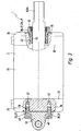
- the linear drive 1 has an elongate housing 2, which has a front and a rear end wall 3, 4, as well as an axially extending therebetween tubular peripheral wall 5.
- the housing 2 designed a total of cylindrical, in particular circular cylindrical.
- the housing 2 In the interior of the housing 2 there is a piston 7 which can be displaced linearly in the direction of the longitudinal axis 6 of the housing 2 and which is coupled for movement with an output part 8 accessible outside the housing 2.
- the output part 8 is a piston rod 8a, which passes through the front end wall 3 to the outside and whose lying outside the housing 2 section is provided with an external thread 12 or other fastening means to which a component to be moved or positioned , For example, a part of a machine, detachably attach.
- the piston 7 is slidably mounted on a defined by the inner surface of the peripheral wall 5 piston tread 13 and is equipped at its outer periphery with circumferential seal means 14, the two piston axially divided by the piston front and rear working chambers 15, 16 by contact with the piston tread 13 fluid-tight from each other split off.
- a housing 2 passes through the fluid channel 17, 18, which opens via a connection opening 19 to the outer surface of the housing 2, to which via suitable connection means 22, a schematically indicated fluid line 21 can be detachably connected.
- the housing 2 is composed of only three components. These are a front end cap 24, a rear end cap 25 and a separate piece of tubing 26 extending therebetween.
- the end caps 24, 25 are cup or cup shaped, each having one associated front or rear end wall 3, 4 transverse to the longitudinal axis 6 extending bottom wall 27 and a thereto, in particular via a curved transition section, subsequent annular or sleeve-shaped side wall 28th
- the diameter of the pipe section 26 corresponds expediently to that of the side wall 28. With its two end faces, the pipe section 26 is in each case butt-shaped against the facing end face of the side wall 28 of the adjoining front or rear end cap 24, 25.
- the wall thickness of the end caps 24, 25 and the pipe section 26 is expediently the same throughout, making use of a relatively thin-walled design. In the embodiment, the wall thickness is in the range of 1.8 mm, with a piston outer diameter of about 125 mm.
- a high quality metal is suitably used, in particular stainless steel.
- the pipe section 26 can be cut to length in any desired length of tube by the meter.
- the end caps 24, 25 can be inexpensively manufactured by deep drawing or pressing.
- stainless steel allows use in an environment where aggressive media is generated. This applies, for example, to application fields in the pharmaceutical and food industry, where linear drives are regularly exposed to aggressive cleaning media.
- piston rod 8a is used for the same reason in particular stainless steel, ie a stainless steel.
- the peripheral wall 5 of the housing 2 is defined in common by the tube piece 26 and the sleeve or annular side walls 28 of the two end caps 24, 25.
- the piston tread 13 is here exclusively on the pipe section 26th
- the separate from home housing components 24, 25, 26 are fixed and in particular permanently connected to each other.
- This connection is made in particular by a gas-tight welded connection 32 in the annular abutting region of the components.
- a laser welding connection in which the components are assembled gas-tight all around without external supply of welding material.
- Each filler 33, 34 consists of a relative to the housing material more cost-effective and preferably also lighter material.
- it is an aluminum material or a polymer material, in particular a plastic material.
- each filling body 33, 34 is slightly larger than the measured in the same direction depth of the associated end cap 24, 25.
- This protruding length portion of the filling body 33, 34 is formed in its dimensions transversely to the longitudinal axis 6 so that it exerts a centering function with respect to the radially outside a piece far axially overlapping pipe section 26.
- the filling body 33, 34 form the mechanical boundary of the working chambers 15, 16 on the piston 7 axially opposite side.
- the piston 7 facing axially front of each filling body 33, 34 carries an impact surface 35 on which the piston 7 bounces to define its end position in its linear motion 23.
- the impact surface 35 may be provided on a separate impact body arranged on the preferably one-piece filler body 33, 34, for example a buffer element attached to the filler body 33, 34. In the embodiment, however, it is formed directly from the front end face of the respective filling body 33, 34.
- Each filler 33, 34 is fixed relative to the associated end cap 24, 25 axially immovable. All existing attachment measures are located in that area of the filling body 33, 34, which adjoins the associated bottom wall 27 to the presently formed directly from the impact surface 35 front of the filling body 33, 34. The attachment measures are limited exclusively to this area, in particular, is the Piston 7 facing front end face of the filling body 33, 34 is not used for fixation fixed to the housing.
- each filling body 33, 34 is fastened exclusively to the end cap 24, 25 surrounding it.
- the pipe section 26 is not involved in this attachment.
- the axially fixed connection between the pipe section 26 and the packing 33, 34 results solely from the fixed connection between pipe section 26 and end cap 24, 25, wherein the latter of the respective associated filling body 33, 34 is fixed.
- each end cap 24, 25 and the filling body 33, 34 inserted into it.
- the components could be glued or welded together.
- each filler 33, 34 is fixed by intervening in him, on the associated end cap 24, 25 supporting fastener 36 on the associated end cap 24, 25.
- Deviating from the embodiment provides a screw.
- fastening means 36 at least one fastening screw 37 is provided, which is guided with a threaded shaft 39 from the outside through a wall opening 38 of the wall of the end cap 24, 25 and screwed into a aligned with this wall opening 38, an internal thread having threaded hole 42 of the packing 33, 34 is.
- the fastening screw 37 is supported with a respect to the threaded shaft 39 wider head 40 from.
- the threaded hole 42 expediently extends axially, in the axial direction of the longitudinal axis 6, wherein the fastening screw 37 passes through the bottom wall 27.
- the side wall 28 is not needed for this type of screw connection.
- the fastening means 36 are effective without the cooperation of the side wall 28 exclusively between the end wall 3, 4 and the associated filling body 33, 34.
- the central opening 45 of the front filling body 33 penetrated by the piston rod 8a can advantageously be provided with an internal thread and designed as a threaded hole 42.
- a fastening screw 37 here is a hollow screw 37 a used, which is attached coaxially to the piston rod 8 a and screwed through the associated wall opening 38 into the opening 45 of the front packing 33.
- the hollow screw 37a simultaneously acts as a support for a bearing surface for the piston rod 8a serving slide bearing surface 46, a fluid outlet from the front working chamber 15 preventing seal ring 47 and an ingress of contaminants preventing scraper ring 48.
- These three components enclose the piston rod 8a respectively coaxial and are slidable on the outer circumference. Sealing ring 47 and scraper ring 48 may be combined in a combined sealing and scraper ring.
- the sliding bearing surface 46 may be part of a fixed in the hollow screw 37 a plain bearing bush.
- a sealing ring 52 arranged around the threaded shaft 39 of the hollow screw 37a cooperates with the inner surface of the opening 45 and prevents undesired fluid leakage.
- a plurality of threaded holes 42 are formed with axial extent in the rear filler 34, in each of which a fastening screw 37 formed by a standard screw is screwed.
- a fastening screw 37 formed by a standard screw is screwed.
- These aforementioned four rear fixing screws 37 can also perform a multiple function by additionally with them a suitable for external attachment of the linear drive 1 holder 53 is externally clamped to the outside with the bottom wall 27 of the rear end cap 25.
- the fastening screws 37 pass through a base plate of the holder 53 and are supported with their heads 40 from it.
- the holder 53 is a so-called pivoting flange, which enables a pivotable mounting of the linear drive 1.
- a holder 53 of a different design for example a so-called foot mounting part, with which a rigid attachment to an external component can be carried out.
- threaded holes 42 with aligned wall openings 38 may also be present in each filler 33, 34, which are not originally used for fixed connection between end cap 24, 25 and packing 33, 34. In FIG. 1 this is indicated by dash-dotted lines in the region of the bottom wall 27 of the front end cap 24, namely in a preferably uniform distribution around the central opening 45.
- end cap 24, 25 has a circular cross section and the associated filling body 33, 34 is also contoured in a circular shape, it is also possible to form mutually complementary threads on the inner circumference of the side wall 28 and on the outer circumference of the filling body 33, which make it possible Fillings 33, 34 without separate fastening screws directly into the end cap 24, 25 screw.
- connection openings 19 The outgoing of the connection openings 19 fluid channels 17, 18 pass through the associated filling body 33, 34 and open to the piston 7 facing the front side 35 from.
- each fluid channel 17, 18 extends partly in a filling body 33, 34 and partly through the associated side wall 28 therethrough.
- the above-mentioned connection opening 19 is formed in a sleeve-shaped connection element 54, which is inserted into a wall opening 55 of the side wall 28 and tightly secured there, for example by a gas-tight cohesive connection, in particular a welded connection or a solder joint.
- connection element 54 and the connection means 22 are arranged, for example in the form of an internal thread, as shown, or in the form of a plug connection device not shown.
- each bottom wall 27 and the associated filling body 33, 34 is an all formed in this bottom wall 27 wall openings 38 together enclosing annular or frame-shaped seal 56. This prevents unwanted leakage.
- 34 can be dispensed with in this case to a special seal. It can be tolerated in the illustrated construction that the filling body 33, 34 is surrounded by the actuating fluid radially outward.
- the filler is expediently flattened on the outer circumference, in order to achieve an anti-twist with respect to the end cap 24, 25 by the adjoining connection element 54 resting thereon.
- an angular correct relative position between the mutually associated, on the one hand in the filling body 33, 34 and the other in the connection element 54 extending longitudinal sections of the Fluid channels 17, 18 guaranteed.
- the anti-rotation measure also facilitates screwing and unscrewing the hollow screw 37a.
- the side walls 28 with the pipe section 26 circumferentially continuously sealed gas-tight. An additional seal is therefore unnecessary.
- Radially within the point of the welded joint 32, the filling body 33, 34 have a circumferential groove 57, which favors the removal of the heat generated during the welding process.
- the piston rod may be hollow.
- the external thread 12 may in this case be part of a bolt-like component which is inserted or screwed into the hollow piston rod.
- a very smooth outer surface of the housing 2 can be realized, which is extremely easy to clean. Since the housing can be made without cutting, if necessary, a cost-effective production is possible.
- both end caps 24, 25 may be identical. They can be made as an identical primitive that then only needs to be punched out in the required places when needed.
Landscapes
- Engineering & Computer Science (AREA)
- Physics & Mathematics (AREA)
- Fluid Mechanics (AREA)
- Mechanical Engineering (AREA)
- General Engineering & Computer Science (AREA)
- Actuator (AREA)
Claims (25)
- Vérin actionné par fluide, avec un boîtier (2) recevant un piston (7) linéairement mobile et définissant deux parois terminales frontales (3, 4) et une paroi périphérique (5) tubulaire s'étendant entre celles-ci, au moins une paroi terminale (3, 4) étant formée par la paroi de fond (27) d'une calotte terminale (24, 25), dont la paroi latérale (28) définit une partie de la longueur de la paroi périphérique (5) et à laquelle se raccorde un tronçon de tube (26) définissant une autre partie de la longueur de la paroi périphérique (5), la calotte terminale (24, 25) renfermant un corps de remplissage (33, 34) s'appuyant intérieurement contre la paroi latérale (28) et la paroi de fond (27) de ladite calotte et fixé en immobilité axiale par rapport à la calotte terminale (24, 25), corps qui porte sur le côté avant une surface d'impact (35) pour le piston (7), axialement avancée par rapport à la paroi terminale (3, 4), le tronçon de tube (26) recouvrant radialement à l'extérieur sur une petite distance axiale le corps de remplissage (33, 34), sans s'appuyer axialement contre ce dernier et tout en assurant un centrage, et le corps de remplissage (33, 34) étant, dans la zone située axialement en arrière de son côté avant, fixé à la calotte terminale (24, 25) du boîtier (2), caractérisé en ce que le corps de remplissage (33, 34) est fixé à la calotte terminale (24, 25) par des moyens de fixation (36) s'engageant dans ledit corps et s'appuyant contre la calotte terminale (24, 25).
- Vérin selon la revendication 1, caractérisé en ce que le corps de remplissage (33, 34) est exclusivement fixé à la calotte terminale (24, 25) du boîtier (2).
- Vérin selon la revendication 1 ou 2, caractérisé en ce que le corps de remplissage (33, 34) est vissé à la calotte terminale (24, 25).
- Vérin selon l'une quelconque des revendications 1 à 3, caractérisé en ce que les moyens de fixation (36) sont actifs entre la paroi terminale (3, 4) de la calotte terminale (24, 25) et le corps de remplissage (33, 34).
- Vérin selon la revendication 4, caractérisé en ce que les moyens de fixation (36) sont actifs exclusivement entre la paroi terminale (3, 4) de la calotte terminale (24, 25) et le corps de remplissage (33, 34), sans coopération de la paroi latérale (28).
- Vérin selon l'une quelconque des revendications 1 à 5, caractérisé en ce qu'au moins un trou taraudé (42) est formé dans le corps de remplissage (33, 34), trou dans lequel est vissée une vis de fixation (37) traversant depuis l'extérieur la paroi de la calotte terminale (24, 25) et s'appuyant par une tête (40) contre la surface extérieure de la calotte terminale (24, 25).
- Vérin selon la revendication 6, caractérisé en ce qu'au moins un trou taraudé s'étend axialement dans le corps de remplissage (33, 34), une vis de fixation (37), s'appuyant extérieurement par sa tête (40) contre la paroi terminale (3, 4) de la calotte terminale (24, 25) et au moyen de laquelle le corps de remplissage (33, 34) est assemblé avec serrage axial à la paroi terminale (3, 4), étant vissée dans ce trou taraudé (42).
- Vérin selon la revendication 7, caractérisé en ce que le boîtier (2) possède un axe longitudinal (6) s'étendant au centre du boîtier, plusieurs trous taraudés (42) répartis tout autour de cet axe longitudinal (6) étant formés dans le corps de remplissage (33, 34), dans lesquels sont ou peuvent être vissées des vis de fixation (37) traversant la paroi terminale (3, 4) de la calotte terminale (24, 25).
- Vérin selon l'une quelconque des revendications 6 à 8, caractérisé en ce qu'une attache (53) permettant la fixation du vérin (1) est en même temps fixée extérieurement sur le boîtier (2) au moyen de la ou des vis de fixation (37).
- Vérin selon la revendication 9, caractérisé en ce que l'attache (53) est conçue pour la fixation pivotante du vérin (1).
- Vérin selon l'une quelconque des revendications 6 à 10, caractérisé en ce qu'une tige de piston (8a) traversant au moins un corps de remplissage (33) et la calotte terminale (24) associée à ce dernier est montée sur le piston (7), le percement (45) du corps de remplissage (33) traversé par la tige de piston (8a) comportant un filetage intérieur dans lequel est vissée une vis de fixation (37) réalisée sous forme de vis creuse (37a), entourant coaxialement la tige de piston (8a) et s'appuyant extérieurement par sa tête (40) contre la paroi terminale (27) de la calotte terminale (24).
- Vérin selon la revendication 11, caractérisé en ce que la vis creuse (37a) porte une surface de palier lisse (46) et/ou un anneau d'étanchéité (47) et/ou un segment racleur (48) pour la tige de piston (8a).
- Vérin selon l'une quelconque des revendications 1 à 12, caractérisé en ce que le corps de remplissage (33, 34) est traversé par un canal de fluide (17, 18) débouchant d'un côté dans la chambre de travail (15, 16) se trouvant entre le corps de remplissage (33, 34) et le piston (7), canal qui débouche de l'autre côté, par l'intermédiaire d'une ouverture de raccordement (19), vers la surface extérieure de la calotte terminale (24, 25).
- Vérin selon la revendication 13, caractérisé en ce qu'un élément de raccordement (54) en forme de douille, définissant l'ouverture de raccordement (19), est fixé en étanchéité sur ou dans un percement (55) de la paroi de la calotte terminale (24, 25), élément qui porte un moyen de raccordement (22) pour le raccordement d'une conduite de fluide (21), par exemple un filetage de raccordement.
- Vérin selon la revendication 14, caractérisé en ce que l'élément de raccordement (54) est assemblé en étanchéité aux gaz par liaison de matière à la paroi de la calotte terminale (24, 25), en particulier au moyen d'un soudage ou d'un brasage.
- Vérin selon l'une quelconque des revendications 1 à 15, caractérisé en ce que le tronçon de tube (26) est fixement assemblé à la paroi latérale (28) de la calotte terminale (24, 25).
- Vérin selon la revendication 16, caractérisé en ce que le tronçon de tube (26) est assemblé par soudage à la paroi latérale (28) de la calotte terminale (24, 25), en particulier par un soudage au laser.
- Vérin selon la revendication 16 ou 17, caractérisé en ce que le tronçon de tube (26) est exclusivement fixé à la paroi latérale (28) de la calotte terminale (24, 25), et il n'existe aucune mesure de fixation directe entre le corps de remplissage (33, 34) et le tronçon de tube (26).
- Vérin selon l'une quelconque des revendications 1 à 18, caractérisé en ce que le tronçon de tube (26) et la/les calotte(s) terminale(s) (24, 25) disposent continûment de la même épaisseur de paroi.
- Vérin selon l'une quelconque des revendications 1 à 19, caractérisé en ce que le tronçon de tube (26) et la/les calotte(s) terminale(s) (24, 25) sont constitués d'acier spécial.
- Vérin selon l'une quelconque des revendications 1 à 20, caractérisé en ce que le/les corps de remplissage (33, 34) sont constitués d'un matériau à base d'aluminium ou d'un matériau polymère.
- Vérin selon l'une quelconque des revendications 1 à 21, caractérisé en ce que le boîtier (2) est constitué de deux calottes terminales (24, 25) et d'un tronçon de tube (26) s'étendant entre celles-ci, les deux calottes terminales (24, 25) étant dotées d'un corps de remplissage (33, 34).
- Vérin selon l'une quelconque des revendications 1 à 22, caractérisé en ce qu'une tige de piston (8a), constituée notamment d'acier spécial et traversant au moins une calotte terminale (24) et le corps de remplissage (33) associé à cette dernière, est montée sur le piston (7).
- Vérin selon l'une quelconque des revendications 1 à 23, caractérisé en ce que le boîtier (2) est réalisé de forme cylindrique, en particulier cylindrique circulaire.
- Vérin selon l'une quelconque des revendications 1 à 24, caractérisé en ce que la calotte terminale (24, 25) est une pièce fabriquée par pression ou par emboutissage.
Applications Claiming Priority (1)
| Application Number | Priority Date | Filing Date | Title |
|---|---|---|---|
| DE102007016431A DE102007016431A1 (de) | 2007-04-05 | 2007-04-05 | Fluidbetätigter Linearantrieb |
Publications (3)
| Publication Number | Publication Date |
|---|---|
| EP1978263A2 EP1978263A2 (fr) | 2008-10-08 |
| EP1978263A3 EP1978263A3 (fr) | 2011-04-27 |
| EP1978263B1 true EP1978263B1 (fr) | 2012-05-16 |
Family
ID=39591819
Family Applications (1)
| Application Number | Title | Priority Date | Filing Date |
|---|---|---|---|
| EP20080002986 Not-in-force EP1978263B1 (fr) | 2007-04-05 | 2008-02-19 | Vérin actionné par fluide |
Country Status (3)
| Country | Link |
|---|---|
| EP (1) | EP1978263B1 (fr) |
| CN (1) | CN101280794B (fr) |
| DE (1) | DE102007016431A1 (fr) |
Cited By (1)
| Publication number | Priority date | Publication date | Assignee | Title |
|---|---|---|---|---|
| DE102017220202B3 (de) | 2017-11-14 | 2019-02-14 | Festo Ag & Co. Kg | Fluidbetätigter Arbeitszylinder |
Families Citing this family (5)
| Publication number | Priority date | Publication date | Assignee | Title |
|---|---|---|---|---|
| DE102009014814A1 (de) * | 2009-03-25 | 2010-09-30 | Festo Ag & Co. Kg | Fluidbetätigter Arbeitszylinder |
| DE102013008408A1 (de) * | 2013-05-16 | 2014-11-20 | Festo Ag & Co. Kg | Antriebseinheit eines fluidbetätigten Linearantriebes und Verfahren zu ihrer Herstellung |
| JP6598079B2 (ja) * | 2016-12-06 | 2019-10-30 | Smc株式会社 | ロッド組立体及び流体圧装置 |
| CN108322231B (zh) * | 2018-03-06 | 2020-10-09 | 青岛海信移动通信技术股份有限公司 | 一种移动终端 |
| CN119712653A (zh) * | 2024-12-30 | 2025-03-28 | 山东百帝气动科技股份有限公司 | 一种具有自润滑功能的气缸 |
Family Cites Families (10)
| Publication number | Priority date | Publication date | Assignee | Title |
|---|---|---|---|---|
| US2518787A (en) * | 1946-01-18 | 1950-08-15 | Vickers Inc | Cylinder construction |
| US4312264A (en) * | 1978-06-09 | 1982-01-26 | Galland Henning Nopak Inc. | Fluid pressure operated cylinder assembly |
| JPS6315306U (fr) | 1986-07-16 | 1988-02-01 | ||
| DE9307412U1 (de) | 1993-05-15 | 1993-07-22 | Tess, Peter, Dipl.-Ing., 6747 Annweiler am Trifels | Kolben-Zylinder-Einheit |
| SE509901C2 (sv) * | 1994-06-15 | 1999-03-22 | Multidoc Hydraulic Ab | Hydraulisk kolvcylinder |
| US5471909A (en) * | 1994-07-26 | 1995-12-05 | Kobelt; Jacob | Fluid cylinder |
| DE19523764A1 (de) * | 1995-06-29 | 1997-01-02 | Schlattl Werner Bavaria Tech | Pneumatische Kolben-Zylinder-Einheit |
| SE507522C2 (sv) | 1996-10-15 | 1998-06-15 | Mecman Ab Rexroth | Tryckfluidcylinder |
| DE10141560C2 (de) | 2001-08-24 | 2003-11-06 | Festo Ag & Co | Verfahren zur Herstellung eines fluidbetätigten Arbeitszylinders |
| CN2727473Y (zh) * | 2004-08-09 | 2005-09-21 | 中国航天科技集团公司第一研究院第十五研究所 | 过盈锁紧型液压缸 |
-
2007
- 2007-04-05 DE DE102007016431A patent/DE102007016431A1/de not_active Withdrawn
-
2008
- 2008-02-19 EP EP20080002986 patent/EP1978263B1/fr not_active Not-in-force
- 2008-04-03 CN CN 200810091319 patent/CN101280794B/zh not_active Expired - Fee Related
Cited By (1)
| Publication number | Priority date | Publication date | Assignee | Title |
|---|---|---|---|---|
| DE102017220202B3 (de) | 2017-11-14 | 2019-02-14 | Festo Ag & Co. Kg | Fluidbetätigter Arbeitszylinder |
Also Published As
| Publication number | Publication date |
|---|---|
| DE102007016431A1 (de) | 2008-10-09 |
| EP1978263A2 (fr) | 2008-10-08 |
| CN101280794B (zh) | 2013-05-22 |
| CN101280794A (zh) | 2008-10-08 |
| EP1978263A3 (fr) | 2011-04-27 |
Similar Documents
| Publication | Publication Date | Title |
|---|---|---|
| DE102007030006B4 (de) | Vakuumventil | |
| EP3090196B1 (fr) | Soupape | |
| EP1978263B1 (fr) | Vérin actionné par fluide | |
| EP4055280B1 (fr) | Cylindre de travail | |
| EP4055279A1 (fr) | Cylindre de travail et procédé pour le fabriquer | |
| EP2396211A1 (fr) | Emmanchement amélioré de carter de crémaillère | |
| EP4055281B1 (fr) | Cylindre de travail | |
| DE19507854B4 (de) | Mehrteilige Dichtungsvorrichtung | |
| DE10141560A1 (de) | Fluidbetätigter Arbeitszylinder und Verfahren zu dessen Herstellung | |
| DE19504207A1 (de) | Arbeitszylinder | |
| DE10134086C2 (de) | Verfahren und Vorrichtung zum Verbinden zweier Bauteile | |
| WO2003101583A1 (fr) | Dispositif de filtration de fluides achemines sous haute pression | |
| EP2350463A1 (fr) | Tube de carter et entraînement linéaire équipé de ce dernier | |
| EP3390844B1 (fr) | Dispositif d'entraînement à membrane à actionnement fluidique et ensemble soupape en étant équipé | |
| EP2873512A1 (fr) | Procédé et dispositif d'estampillage et de liaison de pièces en matière plastique | |
| DE102009014813B4 (de) | Linearantrieb | |
| EP2873871A1 (fr) | Dispositif d'actionnement rotatif fluidique et module d'entraînement associé | |
| EP2495451A1 (fr) | Dispositif d'entraînement rotatif hydraulique | |
| EP4388205B1 (fr) | Ensemble tube de vérin et procédé pour le produire | |
| WO2024125767A1 (fr) | Cylindre de travail à commande fluidique | |
| DE4220415A1 (de) | Zylinder, insbesondere für eine hydraulische Servolenkung | |
| EP2536525B1 (fr) | Élément de serrage hydraulique | |
| EP1402188A1 (fr) | Cylindre de travail | |
| DE10334457A1 (de) | Bremskraftverstärker | |
| DE102004018909B4 (de) | Hydraulikvorrichtung |
Legal Events
| Date | Code | Title | Description |
|---|---|---|---|
| PUAI | Public reference made under article 153(3) epc to a published international application that has entered the european phase |
Free format text: ORIGINAL CODE: 0009012 |
|
| AK | Designated contracting states |
Kind code of ref document: A2 Designated state(s): AT BE BG CH CY CZ DE DK EE ES FI FR GB GR HR HU IE IS IT LI LT LU LV MC MT NL NO PL PT RO SE SI SK TR |
|
| AX | Request for extension of the european patent |
Extension state: AL BA MK RS |
|
| PUAL | Search report despatched |
Free format text: ORIGINAL CODE: 0009013 |
|
| AK | Designated contracting states |
Kind code of ref document: A3 Designated state(s): AT BE BG CH CY CZ DE DK EE ES FI FR GB GR HR HU IE IS IT LI LT LU LV MC MT NL NO PL PT RO SE SI SK TR |
|
| AX | Request for extension of the european patent |
Extension state: AL BA MK RS |
|
| 17P | Request for examination filed |
Effective date: 20110624 |
|
| RIC1 | Information provided on ipc code assigned before grant |
Ipc: F15B 15/14 20060101ALI20110728BHEP Ipc: F15B 15/24 20060101AFI20110728BHEP |
|
| GRAP | Despatch of communication of intention to grant a patent |
Free format text: ORIGINAL CODE: EPIDOSNIGR1 |
|
| GRAS | Grant fee paid |
Free format text: ORIGINAL CODE: EPIDOSNIGR3 |
|
| AKX | Designation fees paid |
Designated state(s): DE FR GB IT |
|
| GRAA | (expected) grant |
Free format text: ORIGINAL CODE: 0009210 |
|
| AK | Designated contracting states |
Kind code of ref document: B1 Designated state(s): DE FR GB IT |
|
| REG | Reference to a national code |
Ref country code: GB Ref legal event code: FG4D Free format text: NOT ENGLISH |
|
| REG | Reference to a national code |
Ref country code: DE Ref legal event code: R096 Ref document number: 502008007169 Country of ref document: DE Effective date: 20120719 |
|
| PLBE | No opposition filed within time limit |
Free format text: ORIGINAL CODE: 0009261 |
|
| STAA | Information on the status of an ep patent application or granted ep patent |
Free format text: STATUS: NO OPPOSITION FILED WITHIN TIME LIMIT |
|
| 26N | No opposition filed |
Effective date: 20130219 |
|
| PGFP | Annual fee paid to national office [announced via postgrant information from national office to epo] |
Ref country code: FR Payment date: 20130315 Year of fee payment: 6 |
|
| REG | Reference to a national code |
Ref country code: DE Ref legal event code: R097 Ref document number: 502008007169 Country of ref document: DE Effective date: 20130219 |
|
| GBPC | Gb: european patent ceased through non-payment of renewal fee |
Effective date: 20130219 |
|
| PG25 | Lapsed in a contracting state [announced via postgrant information from national office to epo] |
Ref country code: GB Free format text: LAPSE BECAUSE OF NON-PAYMENT OF DUE FEES Effective date: 20130219 |
|
| REG | Reference to a national code |
Ref country code: FR Ref legal event code: ST Effective date: 20141031 |
|
| PG25 | Lapsed in a contracting state [announced via postgrant information from national office to epo] |
Ref country code: FR Free format text: LAPSE BECAUSE OF NON-PAYMENT OF DUE FEES Effective date: 20140228 |
|
| PG25 | Lapsed in a contracting state [announced via postgrant information from national office to epo] |
Ref country code: IT Free format text: LAPSE BECAUSE OF NON-PAYMENT OF DUE FEES Effective date: 20140219 |
|
| PGFP | Annual fee paid to national office [announced via postgrant information from national office to epo] |
Ref country code: DE Payment date: 20180124 Year of fee payment: 11 |
|
| REG | Reference to a national code |
Ref country code: DE Ref legal event code: R119 Ref document number: 502008007169 Country of ref document: DE |
|
| PG25 | Lapsed in a contracting state [announced via postgrant information from national office to epo] |
Ref country code: DE Free format text: LAPSE BECAUSE OF NON-PAYMENT OF DUE FEES Effective date: 20190903 |