EP1978230B1 - Centrale thermique, en particulier pour l'utilisation de sources de chaleur à basse température - Google Patents
Centrale thermique, en particulier pour l'utilisation de sources de chaleur à basse température Download PDFInfo
- Publication number
- EP1978230B1 EP1978230B1 EP08005628.6A EP08005628A EP1978230B1 EP 1978230 B1 EP1978230 B1 EP 1978230B1 EP 08005628 A EP08005628 A EP 08005628A EP 1978230 B1 EP1978230 B1 EP 1978230B1
- Authority
- EP
- European Patent Office
- Prior art keywords
- piston
- working medium
- working chamber
- working
- valve
- Prior art date
- Legal status (The legal status is an assumption and is not a legal conclusion. Google has not performed a legal analysis and makes no representation as to the accuracy of the status listed.)
- Active
Links
- 239000002918 waste heat Substances 0.000 claims description 6
- QGZKDVFQNNGYKY-UHFFFAOYSA-N Ammonia Chemical compound N QGZKDVFQNNGYKY-UHFFFAOYSA-N 0.000 claims description 4
- XLYOFNOQVPJJNP-UHFFFAOYSA-N water Substances O XLYOFNOQVPJJNP-UHFFFAOYSA-N 0.000 claims description 4
- 238000009835 boiling Methods 0.000 claims description 3
- 238000004519 manufacturing process Methods 0.000 claims description 3
- 229910021529 ammonia Inorganic materials 0.000 claims description 2
- 229930195733 hydrocarbon Natural products 0.000 claims description 2
- 150000002430 hydrocarbons Chemical class 0.000 claims description 2
- 239000004215 Carbon black (E152) Substances 0.000 claims 1
- LFQSCWFLJHTTHZ-UHFFFAOYSA-N Ethanol Chemical compound CCO LFQSCWFLJHTTHZ-UHFFFAOYSA-N 0.000 description 7
- 239000007789 gas Substances 0.000 description 6
- 238000006073 displacement reaction Methods 0.000 description 4
- 238000002485 combustion reaction Methods 0.000 description 3
- VLKZOEOYAKHREP-UHFFFAOYSA-N n-Hexane Chemical compound CCCCCC VLKZOEOYAKHREP-UHFFFAOYSA-N 0.000 description 3
- 239000002028 Biomass Substances 0.000 description 2
- 239000007788 liquid Substances 0.000 description 2
- 239000000314 lubricant Substances 0.000 description 2
- 238000000034 method Methods 0.000 description 2
- 239000000126 substance Substances 0.000 description 2
- FGRBYDKOBBBPOI-UHFFFAOYSA-N 10,10-dioxo-2-[4-(N-phenylanilino)phenyl]thioxanthen-9-one Chemical compound O=C1c2ccccc2S(=O)(=O)c2ccc(cc12)-c1ccc(cc1)N(c1ccccc1)c1ccccc1 FGRBYDKOBBBPOI-UHFFFAOYSA-N 0.000 description 1
- TVEXGJYMHHTVKP-UHFFFAOYSA-N 6-oxabicyclo[3.2.1]oct-3-en-7-one Chemical compound C1C2C(=O)OC1C=CC2 TVEXGJYMHHTVKP-UHFFFAOYSA-N 0.000 description 1
- 239000012080 ambient air Substances 0.000 description 1
- 239000000969 carrier Substances 0.000 description 1
- 238000006243 chemical reaction Methods 0.000 description 1
- 239000002826 coolant Substances 0.000 description 1
- 230000007423 decrease Effects 0.000 description 1
- 230000002093 peripheral effect Effects 0.000 description 1
- 239000007787 solid Substances 0.000 description 1
Images
Classifications
-
- F—MECHANICAL ENGINEERING; LIGHTING; HEATING; WEAPONS; BLASTING
- F02—COMBUSTION ENGINES; HOT-GAS OR COMBUSTION-PRODUCT ENGINE PLANTS
- F02G—HOT GAS OR COMBUSTION-PRODUCT POSITIVE-DISPLACEMENT ENGINE PLANTS; USE OF WASTE HEAT OF COMBUSTION ENGINES; NOT OTHERWISE PROVIDED FOR
- F02G1/00—Hot gas positive-displacement engine plants
- F02G1/02—Hot gas positive-displacement engine plants of open-cycle type
-
- F—MECHANICAL ENGINEERING; LIGHTING; HEATING; WEAPONS; BLASTING
- F01—MACHINES OR ENGINES IN GENERAL; ENGINE PLANTS IN GENERAL; STEAM ENGINES
- F01C—ROTARY-PISTON OR OSCILLATING-PISTON MACHINES OR ENGINES
- F01C1/00—Rotary-piston machines or engines
- F01C1/30—Rotary-piston machines or engines having the characteristics covered by two or more groups F01C1/02, F01C1/08, F01C1/22, F01C1/24 or having the characteristics covered by one of these groups together with some other type of movement between co-operating members
- F01C1/34—Rotary-piston machines or engines having the characteristics covered by two or more groups F01C1/02, F01C1/08, F01C1/22, F01C1/24 or having the characteristics covered by one of these groups together with some other type of movement between co-operating members having the movement defined in group F01C1/08 or F01C1/22 and relative reciprocation between the co-operating members
- F01C1/344—Rotary-piston machines or engines having the characteristics covered by two or more groups F01C1/02, F01C1/08, F01C1/22, F01C1/24 or having the characteristics covered by one of these groups together with some other type of movement between co-operating members having the movement defined in group F01C1/08 or F01C1/22 and relative reciprocation between the co-operating members with vanes reciprocating with respect to the inner member
-
- F—MECHANICAL ENGINEERING; LIGHTING; HEATING; WEAPONS; BLASTING
- F01—MACHINES OR ENGINES IN GENERAL; ENGINE PLANTS IN GENERAL; STEAM ENGINES
- F01C—ROTARY-PISTON OR OSCILLATING-PISTON MACHINES OR ENGINES
- F01C21/00—Component parts, details or accessories not provided for in groups F01C1/00 - F01C20/00
- F01C21/18—Arrangements for admission or discharge of the working fluid, e.g. constructional features of the inlet or outlet
-
- F—MECHANICAL ENGINEERING; LIGHTING; HEATING; WEAPONS; BLASTING
- F01—MACHINES OR ENGINES IN GENERAL; ENGINE PLANTS IN GENERAL; STEAM ENGINES
- F01K—STEAM ENGINE PLANTS; STEAM ACCUMULATORS; ENGINE PLANTS NOT OTHERWISE PROVIDED FOR; ENGINES USING SPECIAL WORKING FLUIDS OR CYCLES
- F01K25/00—Plants or engines characterised by use of special working fluids, not otherwise provided for; Plants operating in closed cycles and not otherwise provided for
- F01K25/08—Plants or engines characterised by use of special working fluids, not otherwise provided for; Plants operating in closed cycles and not otherwise provided for using special vapours
-
- F—MECHANICAL ENGINEERING; LIGHTING; HEATING; WEAPONS; BLASTING
- F01—MACHINES OR ENGINES IN GENERAL; ENGINE PLANTS IN GENERAL; STEAM ENGINES
- F01K—STEAM ENGINE PLANTS; STEAM ACCUMULATORS; ENGINE PLANTS NOT OTHERWISE PROVIDED FOR; ENGINES USING SPECIAL WORKING FLUIDS OR CYCLES
- F01K7/00—Steam engine plants characterised by the use of specific types of engine; Plants or engines characterised by their use of special steam systems, cycles or processes; Control means specially adapted for such systems, cycles or processes; Use of withdrawn or exhaust steam for feed-water heating
-
- F—MECHANICAL ENGINEERING; LIGHTING; HEATING; WEAPONS; BLASTING
- F01—MACHINES OR ENGINES IN GENERAL; ENGINE PLANTS IN GENERAL; STEAM ENGINES
- F01L—CYCLICALLY OPERATING VALVES FOR MACHINES OR ENGINES
- F01L23/00—Valves controlled by impact by piston, e.g. in free-piston machines
-
- F—MECHANICAL ENGINEERING; LIGHTING; HEATING; WEAPONS; BLASTING
- F02—COMBUSTION ENGINES; HOT-GAS OR COMBUSTION-PRODUCT ENGINE PLANTS
- F02G—HOT GAS OR COMBUSTION-PRODUCT POSITIVE-DISPLACEMENT ENGINE PLANTS; USE OF WASTE HEAT OF COMBUSTION ENGINES; NOT OTHERWISE PROVIDED FOR
- F02G5/00—Profiting from waste heat of combustion engines, not otherwise provided for
- F02G5/02—Profiting from waste heat of exhaust gases
-
- Y—GENERAL TAGGING OF NEW TECHNOLOGICAL DEVELOPMENTS; GENERAL TAGGING OF CROSS-SECTIONAL TECHNOLOGIES SPANNING OVER SEVERAL SECTIONS OF THE IPC; TECHNICAL SUBJECTS COVERED BY FORMER USPC CROSS-REFERENCE ART COLLECTIONS [XRACs] AND DIGESTS
- Y02—TECHNOLOGIES OR APPLICATIONS FOR MITIGATION OR ADAPTATION AGAINST CLIMATE CHANGE
- Y02T—CLIMATE CHANGE MITIGATION TECHNOLOGIES RELATED TO TRANSPORTATION
- Y02T10/00—Road transport of goods or passengers
- Y02T10/10—Internal combustion engine [ICE] based vehicles
- Y02T10/12—Improving ICE efficiencies
Definitions
- the invention relates to a thermal power plant according to the preamble of claim 1.
- a system for motor vehicles which uses the waste heat from the exhaust gas to obtain additional mechanical drive energy, in particular for driving auxiliary units such as the alternator.
- Water serves as the working medium.
- a steam engine drives the steam generated by the exhaust heat.
- thermal power plant of the type mentioned at the outset for the use of heat sources of low temperature emerges from the FR 2531746 A1 forth.
- An organic liquid with a boiling temperature below that of water is used as the working medium.
- the thermal power plant comprises an expansion machine which forms the working space and which has an impeller which is eccentrically mounted in a housing and has displaceable vanes.
- a similar thermal power plant is out DE 102004032215 known.
- Thermal power plant with an inlet valve which can be actuated by a holben are off US 4,050,357 , US 1,203,018 or JP 557 21 2311 known
- the invention has for its object to reduce the effort for obtaining mechanical drive energy from heat sources, in particular heat sources of low temperature.
- the thermal energy contained in the working medium itself is converted into mechanical drive energy. There can be a large difference between the temperatures of the working medium before and after the relaxation and thus a high degree of efficiency.
- Suitable working media are e.g. Ammonia, ethanol, hexane or other hydrocarbons.
- the end values of temperature and pressure which can be achieved by relaxation can be approximated more than that of water vapor to the ambient temperature and the ambient air pressure, which further increases the efficiency.
- the working medium can be introduced into the working space via an inlet valve and this valve comprises an actuating element for bearing against a displaceable boundary wall of the working space formed by the piston, the actuating element being expediently movable against the force of a spring when the limiting wall is displaced.
- the piston connected to a crankshaft comes to a stop near its top dead center against the actuator.
- the pressurized working medium which is brought in from a heat exchanger arranged on the heat source, enters the working space. From the closed position of the valve, the working medium is then enclosed in the work space and can perform mechanical work with relaxation and conversion of the thermal energy contained therein.
- the actuator is expediently connected in one piece to a valve body pressed into a valve seat by the spring.
- the actuator can be a pin coaxial to the valve body, which protrudes into the working space and whose longitudinal axis e.g. coincides with the cylinder axis.
- an outlet valve can be provided which opens at the bottom dead center of the piston and closes when the piston rests against the actuating member.
- Such an outlet valve can be operate a separate linkage driven by the crankshaft. But it is also possible to control the exhaust valve via the actuator.
- thermal power plant can be expediently used to utilize the waste heat from stationary heat engines, from vehicle engines or the waste heat from production processes which generate or consume heat.
- incinerators e.g. for biomass or the like can serve as a heat source.
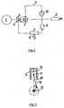
- the heat source 1 shown supplies hot exhaust gases which, in the exemplary embodiment in question, are passed into the atmosphere via a discharge device 2, for example a chimney.
- a discharge device 2 for example a chimney.
- liquids and even solids can also be used as carriers of thermal energy.
- a circuit 3 which e.g. Contains ethanol or another organic substance as the working medium, has a heat exchanger 4 serving as an evaporator 5 and superheater 6, in which heat is transferred from the hot exhaust gases of the heat source 1 to the working medium.
- the pressurized hot steam of the working medium reaches an expansion machine 7, which converts thermal energy contained in the steam of the working medium into mechanical work.
- An arrow 8 is intended to indicate that this mechanical drive energy e.g. can be used to operate a generator.
- the vapor of the working medium expanded in the expansion machine is then liquefied in a condenser 9 and the liquefied working medium is finally fed back to the heat exchanger 4 or evaporator 5 with the aid of a pump 10.
- the heat source 1 is, for example, a stationary motor, possibly a turbine of a power plant.
- the heat source could also be a vehicle engine and both heat from its coolant and its exhaust system can be used.
- Possible heat sources are heat generating or generating Manufacturing processes, for example in chemical industrial plants. All of these heat sources have in common a relatively low temperature of the heat carrier which emits heat to the working medium in the heat exchanger 4.
- possible heat sources are also combustion plants, for example for mine gas, biomass and the like.
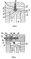
- the expansion machine 7 like an internal combustion engine, may have one or more pistons 11, each of which is connected to a crankshaft 13 via a connecting rod 12.
- the piston 11 moves back and forth between an upper dead center 15 and a lower dead center 16.
- each of the cylinders 14 comprises an inlet valve 17 with a valve body 18 which is pressed into a valve seat 20 by a coil spring 19 coaxial with the valve body, so that an inlet channel 22 leading into the working space 21 of the piston-cylinder unit is blocked when the valve is closed.
- an actuator 23 is formed on the valve body 18 in the form of a pin coaxially projecting from the valve body, which protrudes into the working space 21 and whose axis coincides approximately with the axis of the cylinder 14 in the embodiment concerned.
- a short displacement area 24 before the top dead center of the piston 11 the valve body 18 is lifted out of the valve seat 20 by the piston via the actuating member 23 against the force of the coil spring 19 and the inlet channel 22 is released.
- Working medium under pressure can now flow into the work area.
- the inflow process is completed when the piston 11 has reached the lower limit of the displacement area 24 again.
- the short displacement area 24 corresponds to a relatively large angle of rotation of the crankshaft and thus a relatively large period in which the working medium can flow into the working space.
- the working medium now enclosed in the working space 21 expands approximately adiabatically in the working space by displacing the piston 11 and the connecting rod 12, thermal energy contained in the working medium being converted into mechanical work. With the expansion, at which the pressure of the working medium continuously decreases, the working medium cools down.
- the mechanical work performed is approximately equal to the thermal energy, that of the difference between the temperatures of the working medium before and after its relaxation corresponds.
- the total amount of (positive and negative) mechanical work performed during the inflow process is negligible compared to the mechanical work given off during the expansion of the working medium.
- the cylinders further include an exhaust valve 25 which is opened via a control linkage (not shown) driven by the crankshaft 13 when the piston 11 has reached bottom dead center 16, and is closed again when the piston against the actuator 23 of the valve 17 strikes.
- the outlet valve 25 has a valve body 26 which is pressed against a valve seat 28 by a spring 27.
- An integral part of the valve body 26 is an actuator 29 which projects laterally from the cylinder and which bears against the control linkage mentioned.
- the expansion machine described above can largely be composed of parts of conventional internal combustion engines.
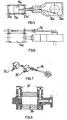
- Expansion machine shown with a piston 11a, a connecting rod 12a and a crankshaft 13a has two working spaces 21a and 21a ', which are formed on opposite sides of the piston which reciprocates in a cylinder 14a.
- a control linkage 34 is used to open and close the work spaces 21 a and 21 a ', as previously described with reference to the embodiment of FIG 3 and 4 is described.
- Valve bodies 35 and 35 ' are connected to the control linkage 34 and are moved into and out of a valve seat by the control linkage 34 depending on the position of the piston 11a or the crankshaft 13a connected to the control linkage.
- a piston rod 38 connected to the piston 11a seals the lubricant-containing space of the crankshaft 13a against the working spaces 21a and 21a '.
- the working medium such as ethanol, is thus kept away from the lubricant.
- the reference number 36 in Fig. 8 indicates the running surface of the piston 11a, the reference number 37 to outlet blocks.
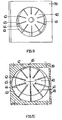
- One in 9 and 10 Expansion machine shown has a housing 39 and an impeller 40 arranged eccentrically in the housing 39. From a circumferential surface 44 of the impeller 40, vanes 42 project radially in guides 41 in the impeller 40. Adjacent vanes each form a working space 43. At the point at which the impeller 40 comes radially closest to an inner surface 45 of the housing 39, the housing 39 has an opening 46 through which working medium under pressure is passed can each enter work space 43 aligned with opening 46. With the rotation of the impeller 40 according to arrow 47, the working medium is enclosed in the relevant working space. The working medium can then expand and relax the working space while driving the impeller.
- the spring-loaded, movable blades 42 adapt to the increased distance between the peripheral surface 44 and the inner surface 45 when the impeller rotates. After a rotation of approximately 180 °, the working space 43 in question has reached its greatest extent. The expanded gas can emerge from the housing 39 at 48.
- thermal power plants or heat engines described above can largely be adapted to heat sources of different temperatures without any structural changes, simply by exchanging the working medium.
Landscapes
- Engineering & Computer Science (AREA)
- Mechanical Engineering (AREA)
- General Engineering & Computer Science (AREA)
- Chemical & Material Sciences (AREA)
- Combustion & Propulsion (AREA)
- Engine Equipment That Uses Special Cycles (AREA)
- Fluid-Driven Valves (AREA)
Claims (3)
- Centrale thermique pour l'utilisation de sources de chaleur à basse température pour utiliser la chaleur perdue de moteurs thermiques stationnaires, la chaleur perdue de processus de production ou la chaleur perdue d'usines d'incinération, comprenant un espace de travail (21) dans lequel peut être introduit un milieu de travail sous pression avec une température d'ébullition inférieure à la température d'ébullition d'eau et lequel peut être dilaté par le milieu de travail tout en effectuant du travail mécanique, dans lequel, pour effectuer le travail mécanique, le milieu de travail ne peut être enfermé dans l'espace de travail (21) qu'en se détendant, dans lequel l'espace de travail (21) est formé par un cylindre (14) et par un piston (11) déplaçable dans le cylindre (14) et entraînant un vilebrequin (13), dans lequel le milieu de travail peut être introduit dans l'espace de travail (21) via une soupape d'admission (17), caractérisée par le fait que la soupape d'admission (17) présente un organe de commande (23) destiné à s'appuyer contre une surface de piston du piston (11), qui délimite l'espace de travail (21), près du point mort haut (15) du piston (11) tout en ouvrant la soupape d'admission (17), dans lequel ledit organe de commande (23) peut être déplacé en déplaçant le piston (11) à l'encontre de la force d'un ressort hélicoïdal (19), que ledit organe de commande (23) est relié en une seule pièce à un corps de soupape (18) pressé dans un siège de soupape (20) par un ressort hélicoïdal (19), et que ledit corps de soupape (18) présente une douille entourant le ressort hélicoïdal (19).
- Centrale thermique selon la revendication 1, caractérisée par le fait que le milieu de travail comprend un hydrocarbure et/ou de l'ammoniac.
- Centrale thermique selon la revendication 1 ou 2, caractérisée par le fait que l'espace de travail peut être vidé via une soupape de sortie qui est commandée par ledit organe de commande.
Applications Claiming Priority (1)
| Application Number | Priority Date | Filing Date | Title |
|---|---|---|---|
| DE102007017357A DE102007017357A1 (de) | 2007-04-03 | 2007-04-03 | Wärmekraftanlage, insbesondere zur Nutzung von Wärmequellen niedriger Temperatur |
Publications (3)
| Publication Number | Publication Date |
|---|---|
| EP1978230A2 EP1978230A2 (fr) | 2008-10-08 |
| EP1978230A3 EP1978230A3 (fr) | 2013-05-29 |
| EP1978230B1 true EP1978230B1 (fr) | 2020-07-22 |
Family
ID=39620259
Family Applications (1)
| Application Number | Title | Priority Date | Filing Date |
|---|---|---|---|
| EP08005628.6A Active EP1978230B1 (fr) | 2007-04-03 | 2008-03-26 | Centrale thermique, en particulier pour l'utilisation de sources de chaleur à basse température |
Country Status (3)
| Country | Link |
|---|---|
| EP (1) | EP1978230B1 (fr) |
| DE (1) | DE102007017357A1 (fr) |
| ES (1) | ES2821742T3 (fr) |
Families Citing this family (2)
| Publication number | Priority date | Publication date | Assignee | Title |
|---|---|---|---|---|
| WO2016146159A1 (fr) * | 2015-03-16 | 2016-09-22 | Aross 3D Gmbh | Moteur à vapeur |
| DE102016102650A1 (de) * | 2016-02-16 | 2017-08-17 | Devetec Gmbh | Wärmekraftmaschine, insbesondere ORC-Motor |
Citations (4)
| Publication number | Priority date | Publication date | Assignee | Title |
|---|---|---|---|---|
| US4283995A (en) * | 1977-10-31 | 1981-08-18 | The United States Of America As Represented By The Administrator Of The National Aeronautics And Space Administration | Reciprocating engines |
| JPS57212311A (en) * | 1981-06-23 | 1982-12-27 | Komatsu Ltd | Piston poppet valve of steam engine |
| DE4219498A1 (de) * | 1992-06-13 | 1993-12-16 | Georg Haase | Solar-Generator |
| DE102004032215A1 (de) * | 2004-07-02 | 2006-01-26 | Richter, Manfred | Durch Über- und Unterdruck angetriebene Kraftmaschine |
Family Cites Families (8)
| Publication number | Priority date | Publication date | Assignee | Title |
|---|---|---|---|---|
| DE166081C (fr) * | 1903-07-18 | 1905-12-16 | ||
| US1203018A (en) * | 1916-02-25 | 1916-10-31 | Chris Larson | Gearless valve mechanism for steam-engines. |
| US4050357A (en) * | 1974-06-25 | 1977-09-27 | Carter Sr J Warne | Steam admission valve and variable clearance volume steam cylinder |
| JPS57131807A (en) * | 1981-02-09 | 1982-08-14 | Tatsuzo Hayashi | Generator set |
| FR2531746B1 (fr) | 1982-08-13 | 1987-04-30 | Centre Atel Const | Installation pour la production d'energie a partir de la chaleur cedee par une source chaude |
| DE19938543A1 (de) * | 1999-08-18 | 2001-02-22 | F & E Ingenieurgmbh Fuer Energ | Automatische Motorventile |
| DE10233763A1 (de) | 2002-07-25 | 2003-04-30 | Devetec Ingenieurgmbh | Hilfsaggregat für Kraftfahrzeuge |
| DE102008013673B3 (de) * | 2008-03-11 | 2009-09-17 | Richard Engelmann | Kolbendampfmaschine für einen solar betriebenen Rankine-Kreislauf |
-
2007
- 2007-04-03 DE DE102007017357A patent/DE102007017357A1/de not_active Ceased
-
2008
- 2008-03-26 EP EP08005628.6A patent/EP1978230B1/fr active Active
- 2008-03-26 ES ES08005628T patent/ES2821742T3/es active Active
Patent Citations (4)
| Publication number | Priority date | Publication date | Assignee | Title |
|---|---|---|---|---|
| US4283995A (en) * | 1977-10-31 | 1981-08-18 | The United States Of America As Represented By The Administrator Of The National Aeronautics And Space Administration | Reciprocating engines |
| JPS57212311A (en) * | 1981-06-23 | 1982-12-27 | Komatsu Ltd | Piston poppet valve of steam engine |
| DE4219498A1 (de) * | 1992-06-13 | 1993-12-16 | Georg Haase | Solar-Generator |
| DE102004032215A1 (de) * | 2004-07-02 | 2006-01-26 | Richter, Manfred | Durch Über- und Unterdruck angetriebene Kraftmaschine |
Also Published As
| Publication number | Publication date |
|---|---|
| ES2821742T3 (es) | 2021-04-27 |
| EP1978230A2 (fr) | 2008-10-08 |
| DE102007017357A1 (de) | 2008-10-09 |
| EP1978230A3 (fr) | 2013-05-29 |
Similar Documents
| Publication | Publication Date | Title |
|---|---|---|
| DE602004009104T2 (de) | Motor mit einer aktiven mono-energie- und/oder bi-energiekammer mit druckluft und/oder zusätzlicher energie und thermodynamischer zyklus davon | |
| EP1330592B1 (fr) | Procede de fonctionnement d'un moteur thermique a vapeur, en particulier comme mecanisme d'entrainement de vehicule | |
| DE112011102951B4 (de) | Abgasturbolader eines Verbrennungsmotors | |
| DE102010020325A1 (de) | Thermokompressionsmotor | |
| EP1978230B1 (fr) | Centrale thermique, en particulier pour l'utilisation de sources de chaleur à basse température | |
| EP3417150B1 (fr) | Moteur thermique, en particulier moteur orc | |
| DE102007049366A1 (de) | Vorrichtung und Verfahren zur Gewinnung von mechanischer Energie aus heißen Gasströmen insbesondere eines Verbrennungsmotors | |
| AT507159B1 (de) | Hubkolbenexpansionsmaschine sowie kolben einer hubkolbenexpansionsmaschine | |
| EP3798413B1 (fr) | Soupape de commande pour un moteur à vapeur, moteur à vapeur comportant une soupape de commande ainsi qu'installation de production combinée électricité-chaleur comportant le moteur à vapeur | |
| DE102004004692A1 (de) | Ventilgesteuerte Expansionsmaschine | |
| EP2116697B1 (fr) | Unité d'entraînement dotée d'un moteur à combustion et d'une machine à piston alternatif automatique sans régulation | |
| WO2012013462A1 (fr) | Moteur à piston pouvant être entraîné par le biais d'un processus de force motrice à vapeur | |
| DE102016119889A1 (de) | Axialkolbenmotor sowie Verfahren zum Betrieb eines Axialkolbenmotors | |
| DE102010018654B4 (de) | Zyklisch arbeitende Wärme-Kraftmaschine | |
| DE102006021928A1 (de) | Vorrichtung zur Erzeugung mechanischer Energie | |
| DE102017206172A1 (de) | Scroll-Expansionsmaschine und Abgasrestwärmenutzungseinrichtung, insbesondere eines Fahrzeuges, mit einer solchen Expansionsmaschine | |
| WO2018103910A1 (fr) | Système pour faire fonctionner un moteur à combustion interne | |
| DE102016006475A1 (de) | Verfahren zum Betreiben einer Brennkraftmaschine sowie entsprechende Brennkraftmaschine | |
| WO2012013463A1 (fr) | Moteur à piston pouvant être entraîné par le biais d'un procédé de force motrice à vapeur | |
| DE102010038542A1 (de) | Kolbenmaschine | |
| WO2018153981A1 (fr) | Dispositif de conversion d'énergie thermique | |
| DE102012210636A1 (de) | Ladungswechseleinrichtung für eine Expansionsmaschine | |
| EP2410140B1 (fr) | Dispositif de lubrification pour un piston | |
| EP3596310B1 (fr) | Moteur à pistons axiaux, système à cycle, ensemble de propulsion, et véhicule à moteur | |
| DE102010063379B4 (de) | Expansionsmaschine und Verfahren zur Abwärmenutzung von Verbrennungskraftmaschinen |
Legal Events
| Date | Code | Title | Description |
|---|---|---|---|
| PUAI | Public reference made under article 153(3) epc to a published international application that has entered the european phase |
Free format text: ORIGINAL CODE: 0009012 |
|
| AK | Designated contracting states |
Kind code of ref document: A2 Designated state(s): AT BE BG CH CY CZ DE DK EE ES FI FR GB GR HR HU IE IS IT LI LT LU LV MC MT NL NO PL PT RO SE SI SK TR |
|
| AX | Request for extension of the european patent |
Extension state: AL BA MK RS |
|
| PUAL | Search report despatched |
Free format text: ORIGINAL CODE: 0009013 |
|
| AK | Designated contracting states |
Kind code of ref document: A3 Designated state(s): AT BE BG CH CY CZ DE DK EE ES FI FR GB GR HR HU IE IS IT LI LT LU LV MC MT NL NO PL PT RO SE SI SK TR |
|
| AX | Request for extension of the european patent |
Extension state: AL BA MK RS |
|
| RIC1 | Information provided on ipc code assigned before grant |
Ipc: F01C 21/08 20060101ALI20130422BHEP Ipc: F02G 1/02 20060101AFI20130422BHEP Ipc: F02B 25/10 20060101ALI20130422BHEP Ipc: F01K 25/08 20060101ALI20130422BHEP Ipc: F02G 5/02 20060101ALI20130422BHEP |
|
| 17P | Request for examination filed |
Effective date: 20131128 |
|
| RBV | Designated contracting states (corrected) |
Designated state(s): AT BE BG CH CY CZ DE DK EE ES FI FR GB GR HR HU IE IS IT LI LT LU LV MC MT NL NO PL PT RO SE SI SK TR |
|
| AKX | Designation fees paid |
Designated state(s): AT BE BG CH CY CZ DE DK EE ES FI FR GB GR HR HU IE IS IT LI LT LU LV MC MT NL NO PL PT RO SE SI SK TR |
|
| RAP1 | Party data changed (applicant data changed or rights of an application transferred) |
Owner name: DEVETEC GMBH |
|
| STAA | Information on the status of an ep patent application or granted ep patent |
Free format text: STATUS: EXAMINATION IS IN PROGRESS |
|
| 17Q | First examination report despatched |
Effective date: 20180413 |
|
| 17Q | First examination report despatched |
Effective date: 20180423 |
|
| 17Q | First examination report despatched |
Effective date: 20180607 |
|
| GRAP | Despatch of communication of intention to grant a patent |
Free format text: ORIGINAL CODE: EPIDOSNIGR1 |
|
| STAA | Information on the status of an ep patent application or granted ep patent |
Free format text: STATUS: GRANT OF PATENT IS INTENDED |
|
| INTG | Intention to grant announced |
Effective date: 20200323 |
|
| GRAS | Grant fee paid |
Free format text: ORIGINAL CODE: EPIDOSNIGR3 |
|
| GRAA | (expected) grant |
Free format text: ORIGINAL CODE: 0009210 |
|
| STAA | Information on the status of an ep patent application or granted ep patent |
Free format text: STATUS: THE PATENT HAS BEEN GRANTED |
|
| AK | Designated contracting states |
Kind code of ref document: B1 Designated state(s): AT BE BG CH CY CZ DE DK EE ES FI FR GB GR HR HU IE IS IT LI LT LU LV MC MT NL NO PL PT RO SE SI SK TR |
|
| REG | Reference to a national code |
Ref country code: GB Ref legal event code: FG4D Free format text: NOT ENGLISH |
|
| REG | Reference to a national code |
Ref country code: CH Ref legal event code: EP |
|
| REG | Reference to a national code |
Ref country code: DE Ref legal event code: R096 Ref document number: 502008017118 Country of ref document: DE |
|
| REG | Reference to a national code |
Ref country code: AT Ref legal event code: REF Ref document number: 1293606 Country of ref document: AT Kind code of ref document: T Effective date: 20200815 |
|
| REG | Reference to a national code |
Ref country code: IE Ref legal event code: FG4D Free format text: LANGUAGE OF EP DOCUMENT: GERMAN |
|
| REG | Reference to a national code |
Ref country code: FI Ref legal event code: FGE |
|
| REG | Reference to a national code |
Ref country code: NL Ref legal event code: FP |
|
| REG | Reference to a national code |
Ref country code: NO Ref legal event code: T2 Effective date: 20200722 |
|
| REG | Reference to a national code |
Ref country code: SE Ref legal event code: TRGR |
|
| REG | Reference to a national code |
Ref country code: LT Ref legal event code: MG4D |
|
| PG25 | Lapsed in a contracting state [announced via postgrant information from national office to epo] |
Ref country code: PT Free format text: LAPSE BECAUSE OF FAILURE TO SUBMIT A TRANSLATION OF THE DESCRIPTION OR TO PAY THE FEE WITHIN THE PRESCRIBED TIME-LIMIT Effective date: 20201123 Ref country code: BG Free format text: LAPSE BECAUSE OF FAILURE TO SUBMIT A TRANSLATION OF THE DESCRIPTION OR TO PAY THE FEE WITHIN THE PRESCRIBED TIME-LIMIT Effective date: 20201022 Ref country code: LT Free format text: LAPSE BECAUSE OF FAILURE TO SUBMIT A TRANSLATION OF THE DESCRIPTION OR TO PAY THE FEE WITHIN THE PRESCRIBED TIME-LIMIT Effective date: 20200722 Ref country code: HR Free format text: LAPSE BECAUSE OF FAILURE TO SUBMIT A TRANSLATION OF THE DESCRIPTION OR TO PAY THE FEE WITHIN THE PRESCRIBED TIME-LIMIT Effective date: 20200722 Ref country code: GR Free format text: LAPSE BECAUSE OF FAILURE TO SUBMIT A TRANSLATION OF THE DESCRIPTION OR TO PAY THE FEE WITHIN THE PRESCRIBED TIME-LIMIT Effective date: 20201023 |
|
| PG25 | Lapsed in a contracting state [announced via postgrant information from national office to epo] |
Ref country code: PL Free format text: LAPSE BECAUSE OF FAILURE TO SUBMIT A TRANSLATION OF THE DESCRIPTION OR TO PAY THE FEE WITHIN THE PRESCRIBED TIME-LIMIT Effective date: 20200722 Ref country code: LV Free format text: LAPSE BECAUSE OF FAILURE TO SUBMIT A TRANSLATION OF THE DESCRIPTION OR TO PAY THE FEE WITHIN THE PRESCRIBED TIME-LIMIT Effective date: 20200722 Ref country code: IS Free format text: LAPSE BECAUSE OF FAILURE TO SUBMIT A TRANSLATION OF THE DESCRIPTION OR TO PAY THE FEE WITHIN THE PRESCRIBED TIME-LIMIT Effective date: 20201122 |
|
| REG | Reference to a national code |
Ref country code: DE Ref legal event code: R097 Ref document number: 502008017118 Country of ref document: DE |
|
| REG | Reference to a national code |
Ref country code: ES Ref legal event code: FG2A Ref document number: 2821742 Country of ref document: ES Kind code of ref document: T3 Effective date: 20210427 |
|
| PG25 | Lapsed in a contracting state [announced via postgrant information from national office to epo] |
Ref country code: RO Free format text: LAPSE BECAUSE OF FAILURE TO SUBMIT A TRANSLATION OF THE DESCRIPTION OR TO PAY THE FEE WITHIN THE PRESCRIBED TIME-LIMIT Effective date: 20200722 Ref country code: DK Free format text: LAPSE BECAUSE OF FAILURE TO SUBMIT A TRANSLATION OF THE DESCRIPTION OR TO PAY THE FEE WITHIN THE PRESCRIBED TIME-LIMIT Effective date: 20200722 Ref country code: EE Free format text: LAPSE BECAUSE OF FAILURE TO SUBMIT A TRANSLATION OF THE DESCRIPTION OR TO PAY THE FEE WITHIN THE PRESCRIBED TIME-LIMIT Effective date: 20200722 Ref country code: CZ Free format text: LAPSE BECAUSE OF FAILURE TO SUBMIT A TRANSLATION OF THE DESCRIPTION OR TO PAY THE FEE WITHIN THE PRESCRIBED TIME-LIMIT Effective date: 20200722 |
|
| PLBE | No opposition filed within time limit |
Free format text: ORIGINAL CODE: 0009261 |
|
| STAA | Information on the status of an ep patent application or granted ep patent |
Free format text: STATUS: NO OPPOSITION FILED WITHIN TIME LIMIT |
|
| 26N | No opposition filed |
Effective date: 20210423 |
|
| PG25 | Lapsed in a contracting state [announced via postgrant information from national office to epo] |
Ref country code: SK Free format text: LAPSE BECAUSE OF FAILURE TO SUBMIT A TRANSLATION OF THE DESCRIPTION OR TO PAY THE FEE WITHIN THE PRESCRIBED TIME-LIMIT Effective date: 20200722 |
|
| PG25 | Lapsed in a contracting state [announced via postgrant information from national office to epo] |
Ref country code: SI Free format text: LAPSE BECAUSE OF FAILURE TO SUBMIT A TRANSLATION OF THE DESCRIPTION OR TO PAY THE FEE WITHIN THE PRESCRIBED TIME-LIMIT Effective date: 20200722 |
|
| PG25 | Lapsed in a contracting state [announced via postgrant information from national office to epo] |
Ref country code: MC Free format text: LAPSE BECAUSE OF FAILURE TO SUBMIT A TRANSLATION OF THE DESCRIPTION OR TO PAY THE FEE WITHIN THE PRESCRIBED TIME-LIMIT Effective date: 20200722 |
|
| REG | Reference to a national code |
Ref country code: BE Ref legal event code: MM Effective date: 20210331 |
|
| PG25 | Lapsed in a contracting state [announced via postgrant information from national office to epo] |
Ref country code: IE Free format text: LAPSE BECAUSE OF NON-PAYMENT OF DUE FEES Effective date: 20210326 |
|
| PG25 | Lapsed in a contracting state [announced via postgrant information from national office to epo] |
Ref country code: BE Free format text: LAPSE BECAUSE OF NON-PAYMENT OF DUE FEES Effective date: 20210331 |
|
| PGFP | Annual fee paid to national office [announced via postgrant information from national office to epo] |
Ref country code: NO Payment date: 20230321 Year of fee payment: 16 Ref country code: FR Payment date: 20230320 Year of fee payment: 16 |
|
| PG25 | Lapsed in a contracting state [announced via postgrant information from national office to epo] |
Ref country code: HU Free format text: LAPSE BECAUSE OF FAILURE TO SUBMIT A TRANSLATION OF THE DESCRIPTION OR TO PAY THE FEE WITHIN THE PRESCRIBED TIME-LIMIT; INVALID AB INITIO Effective date: 20080326 Ref country code: CY Free format text: LAPSE BECAUSE OF FAILURE TO SUBMIT A TRANSLATION OF THE DESCRIPTION OR TO PAY THE FEE WITHIN THE PRESCRIBED TIME-LIMIT Effective date: 20200722 |
|
| PGFP | Annual fee paid to national office [announced via postgrant information from national office to epo] |
Ref country code: SE Payment date: 20230315 Year of fee payment: 16 |
|
| P01 | Opt-out of the competence of the unified patent court (upc) registered |
Effective date: 20230613 |
|
| PGFP | Annual fee paid to national office [announced via postgrant information from national office to epo] |
Ref country code: IT Payment date: 20230331 Year of fee payment: 16 Ref country code: ES Payment date: 20230414 Year of fee payment: 16 Ref country code: CH Payment date: 20230402 Year of fee payment: 16 |
|
| PGFP | Annual fee paid to national office [announced via postgrant information from national office to epo] |
Ref country code: LU Payment date: 20240321 Year of fee payment: 17 Ref country code: NL Payment date: 20240320 Year of fee payment: 17 |
|
| PGFP | Annual fee paid to national office [announced via postgrant information from national office to epo] |
Ref country code: AT Payment date: 20240318 Year of fee payment: 17 |
|
| PGFP | Annual fee paid to national office [announced via postgrant information from national office to epo] |
Ref country code: FI Payment date: 20240319 Year of fee payment: 17 Ref country code: DE Payment date: 20240321 Year of fee payment: 17 Ref country code: GB Payment date: 20240322 Year of fee payment: 17 |