EP1978221A2 - Vorderteil einer Strömungsmaschine, die ein Deflektorsystem für Fremdkörper, wie Hagelkörner, umfasst - Google Patents
Vorderteil einer Strömungsmaschine, die ein Deflektorsystem für Fremdkörper, wie Hagelkörner, umfasst Download PDFInfo
- Publication number
- EP1978221A2 EP1978221A2 EP08102575A EP08102575A EP1978221A2 EP 1978221 A2 EP1978221 A2 EP 1978221A2 EP 08102575 A EP08102575 A EP 08102575A EP 08102575 A EP08102575 A EP 08102575A EP 1978221 A2 EP1978221 A2 EP 1978221A2
- Authority
- EP
- European Patent Office
- Prior art keywords
- turbomachine
- deflector
- front part
- hot air
- foreign bodies
- Prior art date
- Legal status (The legal status is an assumption and is not a legal conclusion. Google has not performed a legal analysis and makes no representation as to the accuracy of the status listed.)
- Granted
Links
Images

Classifications
-
- F—MECHANICAL ENGINEERING; LIGHTING; HEATING; WEAPONS; BLASTING
- F02—COMBUSTION ENGINES; HOT-GAS OR COMBUSTION-PRODUCT ENGINE PLANTS
- F02C—GAS-TURBINE PLANTS; AIR INTAKES FOR JET-PROPULSION PLANTS; CONTROLLING FUEL SUPPLY IN AIR-BREATHING JET-PROPULSION PLANTS
- F02C7/00—Features, components parts, details or accessories, not provided for in, or of interest apart form groups F02C1/00 - F02C6/00; Air intakes for jet-propulsion plants
- F02C7/04—Air intakes for gas-turbine plants or jet-propulsion plants
- F02C7/05—Air intakes for gas-turbine plants or jet-propulsion plants having provisions for obviating the penetration of damaging objects or particles
- F02C7/055—Air intakes for gas-turbine plants or jet-propulsion plants having provisions for obviating the penetration of damaging objects or particles with intake grids, screens or guards
-
- F—MECHANICAL ENGINEERING; LIGHTING; HEATING; WEAPONS; BLASTING
- F01—MACHINES OR ENGINES IN GENERAL; ENGINE PLANTS IN GENERAL; STEAM ENGINES
- F01D—NON-POSITIVE DISPLACEMENT MACHINES OR ENGINES, e.g. STEAM TURBINES
- F01D25/00—Component parts, details, or accessories, not provided for in, or of interest apart from, other groups
- F01D25/02—De-icing means for engines having icing phenomena
-
- F—MECHANICAL ENGINEERING; LIGHTING; HEATING; WEAPONS; BLASTING
- F01—MACHINES OR ENGINES IN GENERAL; ENGINE PLANTS IN GENERAL; STEAM ENGINES
- F01D—NON-POSITIVE DISPLACEMENT MACHINES OR ENGINES, e.g. STEAM TURBINES
- F01D25/00—Component parts, details, or accessories, not provided for in, or of interest apart from, other groups
- F01D25/08—Cooling; Heating; Heat-insulation
- F01D25/10—Heating, e.g. warming-up before starting
-
- F—MECHANICAL ENGINEERING; LIGHTING; HEATING; WEAPONS; BLASTING
- F02—COMBUSTION ENGINES; HOT-GAS OR COMBUSTION-PRODUCT ENGINE PLANTS
- F02C—GAS-TURBINE PLANTS; AIR INTAKES FOR JET-PROPULSION PLANTS; CONTROLLING FUEL SUPPLY IN AIR-BREATHING JET-PROPULSION PLANTS
- F02C7/00—Features, components parts, details or accessories, not provided for in, or of interest apart form groups F02C1/00 - F02C6/00; Air intakes for jet-propulsion plants
- F02C7/04—Air intakes for gas-turbine plants or jet-propulsion plants
- F02C7/047—Heating to prevent icing
-
- F—MECHANICAL ENGINEERING; LIGHTING; HEATING; WEAPONS; BLASTING
- F02—COMBUSTION ENGINES; HOT-GAS OR COMBUSTION-PRODUCT ENGINE PLANTS
- F02C—GAS-TURBINE PLANTS; AIR INTAKES FOR JET-PROPULSION PLANTS; CONTROLLING FUEL SUPPLY IN AIR-BREATHING JET-PROPULSION PLANTS
- F02C7/00—Features, components parts, details or accessories, not provided for in, or of interest apart form groups F02C1/00 - F02C6/00; Air intakes for jet-propulsion plants
- F02C7/04—Air intakes for gas-turbine plants or jet-propulsion plants
- F02C7/05—Air intakes for gas-turbine plants or jet-propulsion plants having provisions for obviating the penetration of damaging objects or particles
-
- F—MECHANICAL ENGINEERING; LIGHTING; HEATING; WEAPONS; BLASTING
- F05—INDEXING SCHEMES RELATING TO ENGINES OR PUMPS IN VARIOUS SUBCLASSES OF CLASSES F01-F04
- F05D—INDEXING SCHEME FOR ASPECTS RELATING TO NON-POSITIVE-DISPLACEMENT MACHINES OR ENGINES, GAS-TURBINES OR JET-PROPULSION PLANTS
- F05D2220/00—Application
- F05D2220/30—Application in turbines
- F05D2220/36—Application in turbines specially adapted for the fan of turbofan engines
-
- F—MECHANICAL ENGINEERING; LIGHTING; HEATING; WEAPONS; BLASTING
- F05—INDEXING SCHEMES RELATING TO ENGINES OR PUMPS IN VARIOUS SUBCLASSES OF CLASSES F01-F04
- F05D—INDEXING SCHEME FOR ASPECTS RELATING TO NON-POSITIVE-DISPLACEMENT MACHINES OR ENGINES, GAS-TURBINES OR JET-PROPULSION PLANTS
- F05D2300/00—Materials; Properties thereof
- F05D2300/50—Intrinsic material properties or characteristics
- F05D2300/505—Shape memory behaviour
Definitions
- the present invention relates generally to a turbomachine front part, whose design makes it possible to prevent / limit the access of foreign bodies, such as hailstones, inside an annular primary channel of the turbomachine. .
- the invention applies to all types of turbomachines, preferably for aircraft, and is preferably applied to turbomachines in which no low-pressure compressor is provided at the inlet of the annular primary channel, this type of turbomachine being generally called "small" because of the small fan diameter associated with it.
- VBV Very Bleed Valve
- the deployed hatches of the slave control system simultaneously make it possible to ensure the scooping of foreign bodies such as hailstones, which, coming into contact with these traps projecting in the primary channel, are redirected towards the secondary annular channel in which they are no longer likely to cause the extinction of the combustion chamber.
- This phenomenon occurs in a similar manner when the technology employed consists of deploying the hatches radially outwardly relative to the annular primary channel, due to the observed sussion effect.
- the inlet of the annular primary channel 16 is generally devoid of booster, so it is also not necessary to provide for the implantation of a slave control system of the type described above, in that the risks of booster pumping obviously do not exist anymore.
- the implementation of such a slave control system on a turbomachine of small size is often impossible because of the small space available between the two annular channels, space in which is usually housed the control system controlled on the larger turbomachines.
- the deflection function of the hailstones can no longer be ensured.
- the subject of the invention is a turbomachine front part comprising an inner ring for supporting the blower output guide vanes, a flow separation spout from which an annular primary channel and an annular turbomachine secondary duct originate.
- it further comprises at least one deflector system intended to prevent / limit the access of foreign bodies such as hailstones inside said primary channel of the turbomachine, said deflector system comprising at least one surface deflector and an actuator for moving said deflector surface from a retracted position to an extended position deflecting foreign bodies, and / or vice versa, said deflector system being mounted on said inner support ferrule of the exit guide vanes fan, so that in the deployed position, a downstream end of said deflecting surface is upstream of said flow separation nozzle.
- one of the peculiarities of the present invention resides in the input supply of the annular primary channel of one or more foreign body deflector systems, such as hailstones, these systems being preferably chosen to be of simple design, inexpensive and compact.
- the foreign bodies can advantageously be deviated from their trajectory by the deflecting surface, upstream of the annular primary channel. In other words, they are thus deflected by the deflecting surface before reaching the entrance of the annular primary channel, so that the risks they penetrate inside the latter channel, after hitting the deflecting surface are almost destroyed.
- the deflector system can easily be installed on any type of turbomachine, and in particular on so-called small turbomachines, without booster or low pressure compressor.
- the invention can then preferably be used to scoop hail as did the VBV servo control systems of the prior art, so that the presence of the latter is no longer required to ensure the function of aforementioned scooping. Therefore, the invention provides an effective and clever solution especially for turbomachines without booster, and therefore also without slave control system type VBV.
- the deflector system provided in the present invention which is implanted on the inner ferrule supporting the blower output guide vanes in order to prevent / limit access of the hailstones within the annular primary channel, allows limiting or eliminating the decline in the separation of primary and secondary streams previously encountered, since the At present, hailstones are at least partly achieved by means of the system according to the invention, and not only because of the retraction of the separation spout for masking the inlet of the primary channel. Therefore, the problem of the prior art concerning unsatisfactory air supply of the annular channel, due to too large recoil of the separation nozzle, can be eradicated by the present invention.
- said deflector system is mounted on said inner support ring of the blower output guide vanes, downstream of said blower output guide vanes, but still upstream of the flow splitter nozzle.
- the deflector system is preferably located near the inlet of the annular primary channel, upstream thereof, this location being preferred because it corresponds to that offering the greatest efficiency to the deflector system.
- a fictitious straight line corresponding to a tangential direction of said downstream end of said deflecting surface, in the deployed position, passes upstream of an upstream end of said separation spout.
- said actuator is made of a shape-memory alloy so as to allow, when it reaches a given transition temperature requiring it to adopt its memorized shape, to place said deflector surface in the deployed position ensuring the deflection of the bodies. foreigners, and said deflector system further comprises elastic return means for, when said actuator has a temperature below said given transition temperature, to return said deflecting surface in its retracted position.
- the nature of the actuator provides great reliability to the deflector system, as well as a long life.
- the reliability obtained is explained in part by a great confidence in the deployment / retraction of the deflecting surface, provided by the physical properties of the material of the shape memory alloy actuator, properties that are directly related to the temperature of the material. .
- the modification of the temperature of the actuator can easily be performed by removing hot air in a suitable portion of the turbomachine, such as for example hot air from the compressor.
- said actuator and said deflecting surface are formed by a same element made of shape memory alloy.
- the actuator is made of shape memory alloy.
- the actuator can then constitute the mechanical connection between the inner support shell and the deflecting surface made of a conventional material, other than the shape memory alloy type.
- said element made of shape memory alloy takes the form of a deflector blade
- said elastic return means take the form of an elastic blade mechanically coupled to said baffle plate, and superimposed on the latter.
- a hot air receiving space may be provided between said elastic blade and said deflector blade, to allow a good distribution of hot air all along the deflector blade made of shape memory alloy.
- the deflector system comprises a hot air inlet communicating with said hot air receiving space, this hot air inlet taking the form of a hollow stud.
- the turbomachine front portion is equipped with a plurality of foreign body deflector systems angularly spaced apart. each other around a longitudinal turbomachine axis.
- each foreign body deflector system on said inner ring of support of the blower output guide vanes is preferably carried out by stamping the hollow stud forming the hot air inlet of the deflector system, and passing through this inner shroud.
- said hot air inlet of each foreign body deflector system passes through said inner support ring of the blower output guide vanes, and said turbomachine front portion comprises a hot air distributor located opposite and radially inward with respect to each deflector system.
- said hot air distributor is preferably supplied with hot air by air coming from a compressor of the turbomachine.
- said distributor has a plurality of outlets angularly spaced from each other about said longitudinal axis of the turbomachine, each outlet being respectively facing a hot air inlet of a foreign body deflector system.
- said deflecting surface takes in longitudinal section the form of a curved line opening upstream and radially outwardly of the turbomachine, this form being entirely adapted to ensure a satisfactory deviation of foreign bodies such as hail.
- said downstream end of the deflecting surface is preferably flush with the outer surface of said inner shroud for supporting the fan outlet guide vanes.
- the invention also relates to a turbomachine comprising a front portion as described above.
- the invention also relates to a deflector system for a turbomachine, intended to prevent / limit the access of foreign bodies such as hailstones inside a primary channel of the turbomachine, said deflector system comprising at least one deflector surface and an actuator for moving said deflector surface from a retracted position to a deployed position ensuring the deflection of foreign bodies.
- said actuator is made of a shape memory alloy so as to allow, when it reaches a given transition temperature that it has to adopt its memorized shape, to place said deflecting surface in the deployed position ensuring the deflection foreign bodies, and said deflector system further comprises elastic return means allowing, when said actuator has a temperature below said temperature of given transition, to recall said deflecting surface in its retracted position.
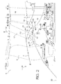
- FIG. figure 2 it is possible to see a front part 1 of an aircraft turbomachine, of the type devoid of a low pressure compressor and of small size.
- This turbomachine 1 is present in the form of a preferred embodiment of the present invention, and has a design substantially similar to that shown in FIG. figure 1 , ie comprising a single HP compressor 3 and a single HP turbine 5, between which there is a combustion chamber 7.
- the elements bearing the same reference numerals correspond to identical or similar elements.
- the front part 1 has in a general flow direction of the fluid through the turbomachine, from upstream to downstream as shown schematically by the arrow 9, d ' an air inlet 4, a blower 6, an inner ring 10 for supporting the fan outlet directing vanes 12, and a stream separation spout 14 from which an annular primary channel 16 originates, and an annular secondary channel 18 arranged radially outwardly relative to the primary channel 16.
- these conventional elements known to those skilled in the art each have an annular shape, centered on a longitudinal axis 22 of the turbomachine.
- the flow of air F passing through the blower 6 and the blower outlet directing vanes 12 divides into two distinct flows following its coming into contact with the upstream end 20 of the separation spout 14, namely in a single flow.
- the separation spout 20 is placed so that the inlet 24 of the primary channel is substantially "masked" by the outer surface of the inner support shell 10, as shown by the dotted line 11 on the figure 2 .
- the decline adopted may be less important than that previously encountered and discussed with reference to the figure 1 showing an embodiment of the prior art, and this for the sake of ensuring a better air supply of the annular primary channel 16.
- the masked nature of the inlet 24 comes from the fact that a hailstone impacting the inner support shell 10 will tend to fuse substantially tangentially to the outer surface of this shell, and this regardless of the trajectory of the hailstone before impact. Consequently, any hailstone impacting the inner support shell 10 before the point 26 from which the above-mentioned fictitious line 11 originates, corresponding to a tangential direction of the section of the ferrule at this point, will be deflected by this ferrule in such a way it will not enter the primary channel 16, but will pass radially outwardly relative to the inlet 24 of this channel 16.
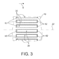
- one of the features of the present invention lies in the implantation of a plurality of deflector systems 30 on the inner support shell 10 bladders 12.
- the deflector systems 30 are angularly spaced from one another about the axis longitudinal 22, as shown schematically in figure 3 . Preferably, they are substantially close to each other in order to jointly form a substantially deflector ring around the inner support shell 24.
- free spaces remain between the directly consecutive deflecting surfaces in the angular / circumferential direction, which makes it possible in particular to continue to allow air to pass towards the primary channel 16.
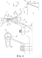
- this comprises a deflector surface 32 and an actuator 34 for moving the deflecting surface from a retracted position shown in this figure to an extended position ensuring the deflection of foreign bodies such as hailstones.
- the actuator 34 and the deflector surface 32 are formed by the same element made of shape memory alloy, as will be detailed hereinafter.
- the deflector system 30 is located generally upstream of the upstream end 20 of the separation spout 14, thus upstream of the inlet 24 of the primary channel 16, while remaining close to it. In addition, it is arranged on the inner support shell 10 downstream of the blower outlet guide vanes 12, which places it substantially at the portion of the ferrule 10 widest in the direction radial diagram shown by the arrow 36, as shown in FIG. figure 2 .
- the actuator 34 and the deflector surface 32 are jointly made using a single deflector blade 40 made of shape memory alloy, so as to allow, when this blade reaches a given transition temperature imposing on it to adopt its memorized shape, to place the deflector surface 32 in the deployed position shown on the figure 4 , ensuring the deflection of foreign bodies such as hailstones.
- the deflector system 30 comprises elastic return means in the form of an elastic blade 42 mechanically coupled to the deflector blade 40, and superimposed thereon. It allows, when the blade 40 has a temperature below the given transition temperature, to return the deflector surface 32 in its retracted position.
- the two blades 40, 42 forming a bimetallic system extend substantially in the direction of the longitudinal axis of the turbomachine, and take each roughly the shape of a rectangle, even if any other form deemed adapted by the person skilled in the art could be adopted without departing from the scope of the invention.
- the deflector blade 40 has a hook 44 radially inwardly into which a downstream end of the elastic blade 42 is inserted. This mechanical coupling makes it possible to retain them substantially. parallel to one another, a hot air receiving space 46 being nevertheless provided between the two blades 40, 42.
- the deflector system 30 has a hollow stud 48 forming a hot air inlet 50 open radially inward, and communicating with the inter-blade space of
- the upstream ends of these two blades 40, 42 are each integral with the hollow stud 48, as shown in FIG. figure 4 .
- the implantation of the deflector system 30 on the inner support shell 10 is preferably by stamping the hollow stud 48 passing through the inner shell 10, its lower radial end 54 deformed by stamping then ensuring the mechanical maintenance of the entire system 30.
- a hot air distributor 56 located opposite the hot air inlet 50 formed by the hollow stud 48, and arranged radially inwardly with respect to this last entry.
- this distributor 56 is supplied with hot air by an air duct 58 connected to the compressor 3 of the turbomachine.
- the distributor 56 has a plurality of outlets 60 spaced angularly from one another about the longitudinal axis of the turbomachine, each outlet 60 then being opposite one of the hot air inlets 50, as shown on the figure 4 . Consequently, the distributor 56, centered on the longitudinal axis of the turbomachine, has as many outlets 60 as are provided with deflector systems 30.
- the hail deflector system 30 and other foreign bodies is operable in the following manner.
- the restoring force delivered by the elastic blade 42 leads to press the deflector blade 40 against the inner support shell 10, as shown by the dotted lines of the figure 4 .
- the deflecting surface 32 then adopts a retracted position in which it has a perfect aerodynamic continuity with the outer surface of the inner support shell 10, so as to disturb as little as possible the air entering the primary channel 16.
- each downstream ends and upstream end 62 of the deflecting surface 32 is flush with the outer surface of the inner support shell 10.
- the shell 10 has a receptacle 65 in which the bimetallic system 40, 42 is housed.
- a suitable control can generate a signal leading to the removal of air at the compressor 3, this hot air is then conveyed to the distributor 56 via the conduit 58.
- the hot air then goes to the outlets 60, then enters the inputs 50 associated, formed by the hollow studs 48.
- the hot air located in each pad 48 then moves towards the inter-blade space 46, from which it can heat the deflector blade 40 made of shape memory alloy.
- the blade 40 reaching its transition temperature rapidly deforms to its memorized shape, in which the deflector surface 32 is placed in its deployed position ensuring the deflection of the hailstones, as shown in solid line on the figure 4 .
- the observed deformation of the deflector blade 40 is effected by counteracting the restoring force generated by the elastic blade 42, which follows the movement of the blade 40 due to their mechanical connection provided by the hook 44.
- the imaginary straight line 64 corresponding to a tangential direction of the downstream end 62, passes upstream of the upstream end 20 of the separating nose 14, but preferably close to this end 20.
- the hailstones impacting the downstream end 62 of the deflecting surface 32, or any other part of this surface 32 will tend to fuse along the imaginary straight line 64, and therefore will not penetrate advantageously within the annular primary channel 16. This follows from the fact that a hailstone tends, after the impact, to fuse tangentially to the wall of the impacted structure, and also to the fact that the deflecting surface 32 takes in longitudinal section the form of a curved line opening upstream and radially outwardly of the turbomachine.
Landscapes
- Engineering & Computer Science (AREA)
- Chemical & Material Sciences (AREA)
- Combustion & Propulsion (AREA)
- Mechanical Engineering (AREA)
- General Engineering & Computer Science (AREA)
- Structures Of Non-Positive Displacement Pumps (AREA)
Applications Claiming Priority (1)
| Application Number | Priority Date | Filing Date | Title |
|---|---|---|---|
| FR0754153A FR2914364B1 (fr) | 2007-03-30 | 2007-03-30 | Partie avant de turbomachine comprenant un systeme de deflecteur de corps etrangers, tels que des grelons. |
Publications (3)
| Publication Number | Publication Date |
|---|---|
| EP1978221A2 true EP1978221A2 (de) | 2008-10-08 |
| EP1978221A3 EP1978221A3 (de) | 2011-02-23 |
| EP1978221B1 EP1978221B1 (de) | 2012-07-04 |
Family
ID=38657259
Family Applications (1)
| Application Number | Title | Priority Date | Filing Date |
|---|---|---|---|
| EP08102575A Active EP1978221B1 (de) | 2007-03-30 | 2008-03-13 | Vorderteil einer Strömungsmaschine, die ein Deflektorsystem für Fremdkörper, wie Hagelkörner, umfasst |
Country Status (7)
| Country | Link |
|---|---|
| US (1) | US7596938B2 (de) |
| EP (1) | EP1978221B1 (de) |
| JP (1) | JP5184168B2 (de) |
| CA (1) | CA2626907C (de) |
| ES (1) | ES2389787T3 (de) |
| FR (1) | FR2914364B1 (de) |
| RU (1) | RU2459965C2 (de) |
Cited By (1)
| Publication number | Priority date | Publication date | Assignee | Title |
|---|---|---|---|---|
| FR3023322A1 (fr) * | 2014-07-03 | 2016-01-08 | Snecma | Manche d'entree d'air pour turbomachine |
Families Citing this family (15)
| Publication number | Priority date | Publication date | Assignee | Title |
|---|---|---|---|---|
| US8452516B1 (en) | 2012-01-31 | 2013-05-28 | United Technologies Corporation | Variable vane scheduling based on flight conditions for inclement weather |
| US9638103B2 (en) | 2013-07-26 | 2017-05-02 | Honeywell International Inc. | Plasma flow control inlet particle separator system |
| US9394827B2 (en) | 2013-08-07 | 2016-07-19 | Honeywell International Inc. | Inlet particle separator system with flow passage through hub and/or shroud |
| US10591164B2 (en) | 2015-03-12 | 2020-03-17 | General Electric Company | Fuel nozzle for a gas turbine engine |
| US10138904B2 (en) | 2016-01-06 | 2018-11-27 | Honeywell International Inc. | Inlet particle separator system with high curvature hub |
| CN107524522B (zh) * | 2016-06-20 | 2021-06-11 | 中国航发商用航空发动机有限责任公司 | 收扩式涡扇发动机分流环 |
| US10508628B2 (en) * | 2016-10-14 | 2019-12-17 | Pratt & Whitney Canada Corp. | Auxiliary power unit inlet assembly with particle separator |
| US10513344B2 (en) | 2016-10-14 | 2019-12-24 | Pratt & Whitney Canada Corp. | Auxiliary power unit assembly with removable inlet filter |
| US10508626B2 (en) | 2016-10-14 | 2019-12-17 | Pratt & Whitney Canada Corp. | Auxiliary power unit inlet assembly with filter |
| US10968771B2 (en) * | 2017-01-12 | 2021-04-06 | General Electric Company | Method and system for ice tolerant bleed takeoff |
| US10670040B2 (en) * | 2017-02-22 | 2020-06-02 | Honeywell International Inc. | Core-protecting fan modules and turbofan engines containing the same |
| US11512646B2 (en) | 2019-12-23 | 2022-11-29 | Unison Industries, Llc | Air starter with bearing cooling |
| EP3885537A1 (de) | 2020-03-26 | 2021-09-29 | Unison Industries LLC | Haltesystem für luftturbinenstarter und verfahren zur herstellung solches systems |
| EP3885539A1 (de) | 2020-03-26 | 2021-09-29 | Unison Industries LLC | Luftturbinenanlasser und verfahren zum auffangen einer turbine eines luftturbinenanlassers |
| JPWO2022230042A1 (de) * | 2021-04-27 | 2022-11-03 |
Family Cites Families (12)
| Publication number | Priority date | Publication date | Assignee | Title |
|---|---|---|---|---|
| BE545919A (de) * | 1955-03-11 | |||
| GB1098058A (en) * | 1965-11-03 | 1968-01-03 | Bristol Siddeley Engines Ltd | Intake assemblies for gas turbine engines |
| US3465950A (en) * | 1968-01-22 | 1969-09-09 | Gen Electric | Separator |
| US4047911A (en) * | 1973-04-12 | 1977-09-13 | Dornier Gmbh | Air intake with deflecting device against foreign objects impinging in the initial direction of air flow at engine nacelles |
| US5061914A (en) * | 1989-06-27 | 1991-10-29 | Tini Alloy Company | Shape-memory alloy micro-actuator |
| US5123240A (en) * | 1990-03-19 | 1992-06-23 | General Electric Co. | Method and apparatus for ejecting foreign matter from the primary flow path of a gas turbine engine |
| FR2664018B1 (fr) * | 1990-06-29 | 1993-08-13 | Gen Electric | Systeme de vanne de derivation. |
| GB2259328B (en) * | 1991-09-03 | 1995-07-19 | Gen Electric | Gas turbine engine variable bleed pivotal flow splitter |
| FR2823532B1 (fr) * | 2001-04-12 | 2003-07-18 | Snecma Moteurs | Systeme de decharge pour turboreacteur ou turbopropulseur a commande simplifiee |
| US6702873B2 (en) * | 2002-04-23 | 2004-03-09 | The Boeing Company | High particle separation efficiency system |
| US7802433B2 (en) * | 2006-09-27 | 2010-09-28 | General Electric Company | Adaptive inertial particle separators and methods of use |
| US7296395B1 (en) * | 2006-12-19 | 2007-11-20 | The Boeing Company | Engine inlet air particle separator with active flow control |
-
2007
- 2007-03-30 FR FR0754153A patent/FR2914364B1/fr not_active Expired - Fee Related
-
2008
- 2008-03-13 ES ES08102575T patent/ES2389787T3/es active Active
- 2008-03-13 EP EP08102575A patent/EP1978221B1/de active Active
- 2008-03-18 US US12/050,456 patent/US7596938B2/en active Active
- 2008-03-25 JP JP2008077142A patent/JP5184168B2/ja active Active
- 2008-03-28 RU RU2008112039/06A patent/RU2459965C2/ru active
- 2008-03-28 CA CA2626907A patent/CA2626907C/fr active Active
Cited By (1)
| Publication number | Priority date | Publication date | Assignee | Title |
|---|---|---|---|---|
| FR3023322A1 (fr) * | 2014-07-03 | 2016-01-08 | Snecma | Manche d'entree d'air pour turbomachine |
Also Published As
| Publication number | Publication date |
|---|---|
| JP2008255986A (ja) | 2008-10-23 |
| JP5184168B2 (ja) | 2013-04-17 |
| EP1978221A3 (de) | 2011-02-23 |
| US20080236133A1 (en) | 2008-10-02 |
| RU2459965C2 (ru) | 2012-08-27 |
| EP1978221B1 (de) | 2012-07-04 |
| US7596938B2 (en) | 2009-10-06 |
| ES2389787T3 (es) | 2012-10-31 |
| RU2008112039A (ru) | 2009-10-10 |
| CA2626907A1 (fr) | 2008-09-30 |
| CA2626907C (fr) | 2014-12-02 |
| FR2914364B1 (fr) | 2009-06-12 |
| FR2914364A1 (fr) | 2008-10-03 |
Similar Documents
| Publication | Publication Date | Title |
|---|---|---|
| EP1978221B1 (de) | Vorderteil einer Strömungsmaschine, die ein Deflektorsystem für Fremdkörper, wie Hagelkörner, umfasst | |
| EP2028375B1 (de) | Nasenhaube für eine Turbomaschine mit integrierter Auswuchtvorrichtung | |
| EP1862644B1 (de) | Leitvorrichtung für den Luftstrom in einem Strahltriebwerk, und enstprechendes Strahltriebwerk und Diffusor | |
| CA2756845C (fr) | Capot d'entree tournant pour turbomachine, comprenant une extremite avant excentree | |
| EP2366060B1 (de) | Gebläse für ein Turbotriebwerk mit einem Auswuchtsystem mit Blindlöchern zur Unterbringung von Gewichten und zugehöriges Turbotriebwerk | |
| EP3833861A1 (de) | Auspuffkonus mit flexibler befestigung | |
| FR2685033A1 (fr) | Stator dirigeant l'entree de l'air a l'interieur d'une turbomachine et procede de montage d'une aube de ce stator. | |
| WO2011023891A1 (fr) | Compresseur de turbomachine ayant des injecteurs d'air | |
| WO2017013360A1 (fr) | Aeronef comportant une turbomachine integree au fuselage arriere a alimentation variable | |
| WO2017013356A1 (fr) | Carter d'échappement d'une turbomachine a durée de vie augmentée | |
| EP1703084B1 (de) | Einrichtung zur Veränderung des Durchtrittsquerschnitts bei einem Turbinenleitapparat | |
| FR3039213A1 (fr) | Turbomachine comportant au moins deux generateurs de gaz et une distribution de flux variable dans la turbine de puissance | |
| FR3027065A1 (fr) | Grille deployable a ailettes pour systeme d'inversion de poussee de turbomachine d'aeronef | |
| FR3080406A1 (fr) | Distributeur de turbine ameliore pour turbomachine | |
| FR2914349A1 (fr) | Interface distributeur couronne a aubes/support pour turbine a vapeur | |
| BE1025263B1 (fr) | Compresseur degivrant de turbomachine et procede de degivrage | |
| EP1489359A1 (de) | Ringförmige Brennkammer für eine Turbomaschine | |
| FR3054526A1 (fr) | Aeronef comportant un turboreacteur integre au fuselage arriere comportant un carenage permettant l'ejection de pales | |
| FR2969209B1 (fr) | Etage de turbine pour turbomachine d'aeronef, presentant une etancheite amelioree entre le flasque aval et les aubes de la turbine | |
| EP4010563B1 (de) | Prallkühlvorrichtung für ein turbomaschinen-aussengehäuse und turbomaschine mit entsprechender vorrichtung | |
| FR2943725A1 (fr) | Capot d'entree tournant pour turbomachine, comprenant une extremite avant en forme de tige | |
| EP2305960B1 (de) | Verdichterablassventil vom primären Kanal und entsprechendes Verfahren zur Vermeidung des Pumpvorgangs | |
| FR3005991A1 (fr) | Dispositif d'interface entre deux elements de turbomachine | |
| FR2979665A1 (fr) | Dispositif de serrage pour pieces de turbomachine, comprenant une gorge annulaire de serrage ouverte radialement vers l'exterieur | |
| FR3098243A1 (fr) | Ensemble récupérateur de fluide pour turbomachine à gaz |
Legal Events
| Date | Code | Title | Description |
|---|---|---|---|
| PUAI | Public reference made under article 153(3) epc to a published international application that has entered the european phase |
Free format text: ORIGINAL CODE: 0009012 |
|
| AK | Designated contracting states |
Kind code of ref document: A2 Designated state(s): AT BE BG CH CY CZ DE DK EE ES FI FR GB GR HR HU IE IS IT LI LT LU LV MC MT NL NO PL PT RO SE SI SK TR |
|
| AX | Request for extension of the european patent |
Extension state: AL BA MK RS |
|
| PUAL | Search report despatched |
Free format text: ORIGINAL CODE: 0009013 |
|
| AK | Designated contracting states |
Kind code of ref document: A3 Designated state(s): AT BE BG CH CY CZ DE DK EE ES FI FR GB GR HR HU IE IS IT LI LT LU LV MC MT NL NO PL PT RO SE SI SK TR |
|
| AX | Request for extension of the european patent |
Extension state: AL BA MK RS |
|
| 17P | Request for examination filed |
Effective date: 20110727 |
|
| AKX | Designation fees paid |
Designated state(s): AT BE BG CH CY CZ DE DK EE ES FI FR GB GR HR HU IE IS IT LI LT LU LV MC MT NL NO PL PT RO SE SI SK TR |
|
| GRAP | Despatch of communication of intention to grant a patent |
Free format text: ORIGINAL CODE: EPIDOSNIGR1 |
|
| RIC1 | Information provided on ipc code assigned before grant |
Ipc: F02C 7/05 20060101ALI20120130BHEP Ipc: F02K 3/075 20060101ALI20120130BHEP Ipc: F02C 7/055 20060101ALI20120130BHEP Ipc: F02C 7/052 20060101AFI20120130BHEP |
|
| RIN1 | Information on inventor provided before grant (corrected) |
Inventor name: BEHAGHEL, LAURENT Inventor name: ROUSSELIN, STEPHANE Inventor name: BART, JACQUES, RENE |
|
| GRAS | Grant fee paid |
Free format text: ORIGINAL CODE: EPIDOSNIGR3 |
|
| GRAA | (expected) grant |
Free format text: ORIGINAL CODE: 0009210 |
|
| AK | Designated contracting states |
Kind code of ref document: B1 Designated state(s): AT BE BG CH CY CZ DE DK EE ES FI FR GB GR HR HU IE IS IT LI LT LU LV MC MT NL NO PL PT RO SE SI SK TR |
|
| REG | Reference to a national code |
Ref country code: GB Ref legal event code: FG4D Free format text: NOT ENGLISH |
|
| REG | Reference to a national code |
Ref country code: CH Ref legal event code: EP |
|
| REG | Reference to a national code |
Ref country code: AT Ref legal event code: REF Ref document number: 565268 Country of ref document: AT Kind code of ref document: T Effective date: 20120715 |
|
| REG | Reference to a national code |
Ref country code: IE Ref legal event code: FG4D Free format text: LANGUAGE OF EP DOCUMENT: FRENCH |
|
| REG | Reference to a national code |
Ref country code: DE Ref legal event code: R096 Ref document number: 602008016945 Country of ref document: DE Effective date: 20120830 |
|
| REG | Reference to a national code |
Ref country code: SE Ref legal event code: TRGR |
|
| REG | Reference to a national code |
Ref country code: ES Ref legal event code: FG2A Ref document number: 2389787 Country of ref document: ES Kind code of ref document: T3 Effective date: 20121031 |
|
| REG | Reference to a national code |
Ref country code: AT Ref legal event code: MK05 Ref document number: 565268 Country of ref document: AT Kind code of ref document: T Effective date: 20120704 |
|
| REG | Reference to a national code |
Ref country code: NL Ref legal event code: VDEP Effective date: 20120704 |
|
| PG25 | Lapsed in a contracting state [announced via postgrant information from national office to epo] |
Ref country code: SI Free format text: LAPSE BECAUSE OF FAILURE TO SUBMIT A TRANSLATION OF THE DESCRIPTION OR TO PAY THE FEE WITHIN THE PRESCRIBED TIME-LIMIT Effective date: 20120704 |
|
| REG | Reference to a national code |
Ref country code: LT Ref legal event code: MG4D Effective date: 20120704 |
|
| PG25 | Lapsed in a contracting state [announced via postgrant information from national office to epo] |
Ref country code: HR Free format text: LAPSE BECAUSE OF FAILURE TO SUBMIT A TRANSLATION OF THE DESCRIPTION OR TO PAY THE FEE WITHIN THE PRESCRIBED TIME-LIMIT Effective date: 20120704 Ref country code: CY Free format text: LAPSE BECAUSE OF FAILURE TO SUBMIT A TRANSLATION OF THE DESCRIPTION OR TO PAY THE FEE WITHIN THE PRESCRIBED TIME-LIMIT Effective date: 20120704 Ref country code: NO Free format text: LAPSE BECAUSE OF FAILURE TO SUBMIT A TRANSLATION OF THE DESCRIPTION OR TO PAY THE FEE WITHIN THE PRESCRIBED TIME-LIMIT Effective date: 20121004 Ref country code: LT Free format text: LAPSE BECAUSE OF FAILURE TO SUBMIT A TRANSLATION OF THE DESCRIPTION OR TO PAY THE FEE WITHIN THE PRESCRIBED TIME-LIMIT Effective date: 20120704 Ref country code: FI Free format text: LAPSE BECAUSE OF FAILURE TO SUBMIT A TRANSLATION OF THE DESCRIPTION OR TO PAY THE FEE WITHIN THE PRESCRIBED TIME-LIMIT Effective date: 20120704 Ref country code: IS Free format text: LAPSE BECAUSE OF FAILURE TO SUBMIT A TRANSLATION OF THE DESCRIPTION OR TO PAY THE FEE WITHIN THE PRESCRIBED TIME-LIMIT Effective date: 20121104 Ref country code: AT Free format text: LAPSE BECAUSE OF FAILURE TO SUBMIT A TRANSLATION OF THE DESCRIPTION OR TO PAY THE FEE WITHIN THE PRESCRIBED TIME-LIMIT Effective date: 20120704 |
|
| PG25 | Lapsed in a contracting state [announced via postgrant information from national office to epo] |
Ref country code: GR Free format text: LAPSE BECAUSE OF FAILURE TO SUBMIT A TRANSLATION OF THE DESCRIPTION OR TO PAY THE FEE WITHIN THE PRESCRIBED TIME-LIMIT Effective date: 20121005 Ref country code: PL Free format text: LAPSE BECAUSE OF FAILURE TO SUBMIT A TRANSLATION OF THE DESCRIPTION OR TO PAY THE FEE WITHIN THE PRESCRIBED TIME-LIMIT Effective date: 20120704 Ref country code: LV Free format text: LAPSE BECAUSE OF FAILURE TO SUBMIT A TRANSLATION OF THE DESCRIPTION OR TO PAY THE FEE WITHIN THE PRESCRIBED TIME-LIMIT Effective date: 20120704 Ref country code: PT Free format text: LAPSE BECAUSE OF FAILURE TO SUBMIT A TRANSLATION OF THE DESCRIPTION OR TO PAY THE FEE WITHIN THE PRESCRIBED TIME-LIMIT Effective date: 20121105 |
|
| PG25 | Lapsed in a contracting state [announced via postgrant information from national office to epo] |
Ref country code: NL Free format text: LAPSE BECAUSE OF FAILURE TO SUBMIT A TRANSLATION OF THE DESCRIPTION OR TO PAY THE FEE WITHIN THE PRESCRIBED TIME-LIMIT Effective date: 20120704 |
|
| PG25 | Lapsed in a contracting state [announced via postgrant information from national office to epo] |
Ref country code: EE Free format text: LAPSE BECAUSE OF FAILURE TO SUBMIT A TRANSLATION OF THE DESCRIPTION OR TO PAY THE FEE WITHIN THE PRESCRIBED TIME-LIMIT Effective date: 20120704 Ref country code: RO Free format text: LAPSE BECAUSE OF FAILURE TO SUBMIT A TRANSLATION OF THE DESCRIPTION OR TO PAY THE FEE WITHIN THE PRESCRIBED TIME-LIMIT Effective date: 20120704 Ref country code: DK Free format text: LAPSE BECAUSE OF FAILURE TO SUBMIT A TRANSLATION OF THE DESCRIPTION OR TO PAY THE FEE WITHIN THE PRESCRIBED TIME-LIMIT Effective date: 20120704 Ref country code: CZ Free format text: LAPSE BECAUSE OF FAILURE TO SUBMIT A TRANSLATION OF THE DESCRIPTION OR TO PAY THE FEE WITHIN THE PRESCRIBED TIME-LIMIT Effective date: 20120704 |
|
| PLBE | No opposition filed within time limit |
Free format text: ORIGINAL CODE: 0009261 |
|
| STAA | Information on the status of an ep patent application or granted ep patent |
Free format text: STATUS: NO OPPOSITION FILED WITHIN TIME LIMIT |
|
| PG25 | Lapsed in a contracting state [announced via postgrant information from national office to epo] |
Ref country code: SK Free format text: LAPSE BECAUSE OF FAILURE TO SUBMIT A TRANSLATION OF THE DESCRIPTION OR TO PAY THE FEE WITHIN THE PRESCRIBED TIME-LIMIT Effective date: 20120704 |
|
| 26N | No opposition filed |
Effective date: 20130405 |
|
| PG25 | Lapsed in a contracting state [announced via postgrant information from national office to epo] |
Ref country code: BG Free format text: LAPSE BECAUSE OF FAILURE TO SUBMIT A TRANSLATION OF THE DESCRIPTION OR TO PAY THE FEE WITHIN THE PRESCRIBED TIME-LIMIT Effective date: 20121004 |
|
| REG | Reference to a national code |
Ref country code: DE Ref legal event code: R097 Ref document number: 602008016945 Country of ref document: DE Effective date: 20130405 |
|
| BERE | Be: lapsed |
Owner name: SNECMA Effective date: 20130331 |
|
| PG25 | Lapsed in a contracting state [announced via postgrant information from national office to epo] |
Ref country code: MC Free format text: LAPSE BECAUSE OF NON-PAYMENT OF DUE FEES Effective date: 20130331 |
|
| REG | Reference to a national code |
Ref country code: CH Ref legal event code: PL |
|
| REG | Reference to a national code |
Ref country code: IE Ref legal event code: MM4A |
|
| PG25 | Lapsed in a contracting state [announced via postgrant information from national office to epo] |
Ref country code: BE Free format text: LAPSE BECAUSE OF NON-PAYMENT OF DUE FEES Effective date: 20130331 Ref country code: CH Free format text: LAPSE BECAUSE OF NON-PAYMENT OF DUE FEES Effective date: 20130331 Ref country code: IE Free format text: LAPSE BECAUSE OF NON-PAYMENT OF DUE FEES Effective date: 20130313 Ref country code: LI Free format text: LAPSE BECAUSE OF NON-PAYMENT OF DUE FEES Effective date: 20130331 |
|
| REG | Reference to a national code |
Ref country code: ES Ref legal event code: FD2A Effective date: 20140606 |
|
| PG25 | Lapsed in a contracting state [announced via postgrant information from national office to epo] |
Ref country code: MT Free format text: LAPSE BECAUSE OF FAILURE TO SUBMIT A TRANSLATION OF THE DESCRIPTION OR TO PAY THE FEE WITHIN THE PRESCRIBED TIME-LIMIT Effective date: 20120704 |
|
| PG25 | Lapsed in a contracting state [announced via postgrant information from national office to epo] |
Ref country code: ES Free format text: LAPSE BECAUSE OF NON-PAYMENT OF DUE FEES Effective date: 20130314 |
|
| PG25 | Lapsed in a contracting state [announced via postgrant information from national office to epo] |
Ref country code: TR Free format text: LAPSE BECAUSE OF FAILURE TO SUBMIT A TRANSLATION OF THE DESCRIPTION OR TO PAY THE FEE WITHIN THE PRESCRIBED TIME-LIMIT Effective date: 20120704 |
|
| PG25 | Lapsed in a contracting state [announced via postgrant information from national office to epo] |
Ref country code: HU Free format text: LAPSE BECAUSE OF FAILURE TO SUBMIT A TRANSLATION OF THE DESCRIPTION OR TO PAY THE FEE WITHIN THE PRESCRIBED TIME-LIMIT; INVALID AB INITIO Effective date: 20080313 Ref country code: LU Free format text: LAPSE BECAUSE OF NON-PAYMENT OF DUE FEES Effective date: 20130313 |
|
| REG | Reference to a national code |
Ref country code: FR Ref legal event code: PLFP Year of fee payment: 9 |
|
| REG | Reference to a national code |
Ref country code: FR Ref legal event code: PLFP Year of fee payment: 10 |
|
| REG | Reference to a national code |
Ref country code: FR Ref legal event code: CD Owner name: SAFRAN AIRCRAFT ENGINES, FR Effective date: 20170717 |
|
| REG | Reference to a national code |
Ref country code: FR Ref legal event code: PLFP Year of fee payment: 11 |
|
| PGFP | Annual fee paid to national office [announced via postgrant information from national office to epo] |
Ref country code: IT Payment date: 20250218 Year of fee payment: 18 |
|
| PGFP | Annual fee paid to national office [announced via postgrant information from national office to epo] |
Ref country code: SE Payment date: 20260323 Year of fee payment: 19 |
|
| PGFP | Annual fee paid to national office [announced via postgrant information from national office to epo] |
Ref country code: GB Payment date: 20260324 Year of fee payment: 19 |
|
| PGFP | Annual fee paid to national office [announced via postgrant information from national office to epo] |
Ref country code: DE Payment date: 20260320 Year of fee payment: 19 |
|
| PGFP | Annual fee paid to national office [announced via postgrant information from national office to epo] |
Ref country code: FR Payment date: 20260324 Year of fee payment: 19 |