EP1978188A2 - Square-spindle with clamping means - Google Patents
Square-spindle with clamping means Download PDFInfo
- Publication number
- EP1978188A2 EP1978188A2 EP20080002282 EP08002282A EP1978188A2 EP 1978188 A2 EP1978188 A2 EP 1978188A2 EP 20080002282 EP20080002282 EP 20080002282 EP 08002282 A EP08002282 A EP 08002282A EP 1978188 A2 EP1978188 A2 EP 1978188A2
- Authority
- EP
- European Patent Office
- Prior art keywords
- square
- recess
- square pin
- pin
- spindle according
- Prior art date
- Legal status (The legal status is an assumption and is not a legal conclusion. Google has not performed a legal analysis and makes no representation as to the accuracy of the status listed.)
- Withdrawn
Links
Images


Classifications
-
- E—FIXED CONSTRUCTIONS
- E05—LOCKS; KEYS; WINDOW OR DOOR FITTINGS; SAFES
- E05B—LOCKS; ACCESSORIES THEREFOR; HANDCUFFS
- E05B3/00—Fastening knobs or handles to lock or latch parts
- E05B3/04—Fastening the knob or the handle shank to the spindle by screws, springs or snap bolts
Definitions
- the present invention relates to a square pin for door or window handles, preferably for door handle.
- Square pins in the field of door or window fittings are well known and widely used.
- a square pin as a pusher mandrel is inserted through a square hole of a lock nut, and there are at one or both ends suitable handles, especially pushers, put on. In this case, one end of the square pin is inserted into a square hole in the handle.
- the object of the present invention is to provide a square pin, a possible backlash-free, improved attachment of the pusher on the square pin with the largest possible contact area waiving the use of clamping or grub screws that extend to the outside of the pusher, allows.
- the square pin according to the invention is characterized in that at least in one of its end regions a recess is provided, which is formed in the region of an edge and two adjacent to these side surfaces of the square pin, that in the recess a two mutually perpendicular pressing surfaces exhibiting, displaceable in the radial direction Clamping element is arranged, wherein the pressing surfaces each face the remaining in the region of the recess side surfaces, and that between the square pin and the clamping element is provided an elastic element for applying an outwardly acting pressing force on the pressing surfaces.
- the pressing force thus acts in the direction of increasing the circumference of the square pin, so that in an assembly position all four side surfaces in the end, ie the two remaining side surfaces of the square pin and the two pressing surfaces of the clamping element are pressed against the four inner surfaces of a square hole ,
- the pressing force is applied by the elastic element radially to the longitudinal axis of the square pin in opposite directions between each other diagonally opposite edges of the square pin or of the clamping element.
- the pressing force thus vectorial components acting perpendicular to all four contact surfaces and thus caulk the square pin according to the invention reliably in the square hole.
- an advantage of this invention is that the contact areas between the square pin and the square hole extend approximately over the entire peripheral surface of the square hole and all four contact surfaces are subjected to approximately equal pressing force, thereby avoiding backlash between the square pin and a handle provided with the square hole ,
- the said pressing surfaces may preferably have a friction-increasing surface in order to be able to absorb additional axial forces between the square pin and the handle provided with the square hole.
- An increase in friction can be achieved by any means, e.g. be achieved by a roughened surface or by small barbs on the pressing surfaces.
- the pressing surfaces in the unmounted state project beyond the cross-section of the square pin given in a recess-free region.
- the elastic element When introduced into the square hole, the elastic element is compressed by the reduction in cross-section associated therewith, whereby the pressing force that can be applied by the elastic element is increased.
- the elastic element is formed as an elastomer.
- Such an elastic element is inexpensive to manufacture and provides a sufficient pressing force due to its compressibility.
- the clamping element is held by means of two mutually opposite in the longitudinal direction of the square pin undercuts in the recess, which limit movement of the clamping element in the direction of the pressing force.
- the undercuts thus cause the clamping element can not be completely pushed out of the recess in an unmounted state by the elastic element. This makes it possible to arrange the elastic element already with a certain bias between the clamping element and the square pin.
- the clamping element in a direction perpendicular to the direction of the pressing force and perpendicular to the longitudinal axis of the square pin in the recess can be inserted.
- a simple assembly of square pin and clamping element is made possible despite the undercut.
- the square pin in the region of the recess has an end-side longitudinal bore which extends with a part of its cross-section in the square pin and with a further part of its cross-section in the clamping element.
- This bore provides a simple way to produce receptacle for the elastic element without the size of the pressing surfaces or the side surfaces of the square pin is reduced in the region of the recess.
- the elastic element is arranged in the longitudinal bore and held in particular in this by press fit.
- a receptacle for the elastic element is created by the longitudinal bore.
- the elastic element is a spring element.
- the spring element may be formed as a leaf spring or as a spiral spring.
- the clamping element preferably has an inlet bevel at an end section facing the end region of the square pin in order to facilitate insertion of the square pin into a receptacle.
- this facilitates the insertion into a square hole by the elastic element is compressed during a Monatagevorgangs substantially by the interaction of inlet slope and square hole.
- the pressing force is generated and the circumference of the square pin in a clamping area adapted to the size of the square hole.
- the recess is formed according to a further preferred embodiment in the region of an end face of the square pin.
- the manufacturing process of the square pin is somewhat simplified. This variant can be used when the above-mentioned undercuts should not be provided.
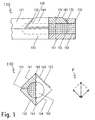
- Fig. 1 is an end portion of a square pin 110 shown according to a first embodiment, wherein the representation is selected so that in side view two side surfaces 121, 122 of the square pin 110 are visible.
- the other two side surfaces 123, 124 are located on the opposite side, but can be seen in the front view.
- the square pin 110 has a recess 130 is introduced, which extends along the end portion of the square pin 110, but ends at a distance from an end face 132 of the square pin 110.
- the recess 130 comprises the side surfaces 121, 123 and an upper edge 162 lying between them. The recess 130 thus extends diagonally across the cross section of the square pin 110.
- the boundary surfaces of the recess 130 which are spaced apart from one another in the longitudinal direction of the square pin 110, are each inclined towards the recess 130 so that they form two undercuts 136 which are spaced apart in the longitudinal direction and by means of which a clamping piece 134 arranged in the recess 130 can be held in the recess 130.
- the clamping piece 134 has preferably in its the end face 132 of the square pin 110 facing the upper end portion in an Fig. 1 inlet bevel, not shown, in order to facilitate insertion of the square pin 110 with clamping piece 134 in a receptacle.
- the clamping piece 134 has two pressing surfaces 141, 142, wherein the pressing surface 141 extends parallel to the side surface 121 and the pressing surface 142 parallel to the side surface 123.
- the square pin 110 is provided with a front side introduced, central longitudinal bore 150, which extends in the axial direction seen from the end face 132 to behind the recess 130.
- the longitudinal bore 150 also includes a portion of the clamping piece 134, so that in each case the clamping piece 134 and the square pin 110 in the region of the recess 130 have approximately a recess in the form of a halved in the axial direction of the cylinder.
- a cylindrical receptacle for an elastomeric element 152 is formed, which is held therein by press fit.
- the clamping force to be achieved is influenced by the choice of material of the elastomer element 152. If the elastomer element 152 is formed as a hollow cylinder, the clamping force can be additionally influenced by the wall thickness of the hollow cylinder.
- the longitudinal bore 150 may have a slightly smaller diameter in the region of the clamping piece 134 than in the region of the square pin 110. In this way, an additional increase in the clamping force can be achieved because then in the clamping piece 134 for the elastomeric element 152 is less space available.
- the difference between the radii of the bore 150 may be, for example, about 0.5 mm.
- the undercuts 136 and the longitudinal bore 150 in the region of the clamping piece 134 are arranged so that the pressing surfaces 141, 142 with the elastomer element 152 inserted protrude slightly out of the planes defined by the side surfaces 121, 123.
- the cross section is usually only slightly larger than the original cross section of the square pin 110.
- the clamping piece 134 initially protrudes beyond the cross section of the square hole and is pressed somewhat into the recess 130 by the insertion process.
- the elastomer element 152 is compressed.
- the compression creates a pressing force which initially acts between the diagonally opposite edges 161, 162 of the square pin 110 and of the clamping piece 134.
- a in Fig. 1 can be divided vectorially into mutually perpendicular components acting between the side surface 124 and the opposite pressing surface 141 and the other between the side surface 122 and the opposite pressing surface 142th Act.
- Fig. 2 shows a square pin 210 according to a second embodiment, in which in an end portion 212 in the region of two adjacent side surfaces 221, 223, a recess 230 is inserted, in contrast to the first embodiment of Fig. 1 a portion of an end face 232 of the square pin 210 includes.
- a clamping piece 234 is arranged, which has two mutually perpendicular pressing surfaces 241, 242, which protrude in an unassembled state a little over each extending parallel to these side surfaces 221 and 223.
- the end portion 212 of the square pin 210 is provided with two longitudinally spaced radial bores 270, each having a shoulder 272 in its lower portion.
- a coil spring 274 is arranged in each case, which is supported on the one hand on an underside 276 of the clamping piece 234 and on the other hand on the shoulder 272.
- the underside 276 of the clamping piece 234 has two hollow cylindrical rivet portions 278 each extending through the coil springs 274 and the radial bores 270 and bent radially outward at its opposite end from the bottom 276.
- the end portion 212 is provided on its underside with an extending over the length of the end portion 212 recess 290, whose depth is dimensioned so that the bent rivet portions 278 do not protrude beyond the cross section of the square pin 210.
- the clamping piece 234 is secured in the radial bores 270, wherein a bias of the coil springs 274 is possible. Between the end portion 212 of the square pin 210 and the clamping piece 234 remains in the unmounted state of the square pin 210, a distance which decreases when inserting the square pin 210 into a square hole, so that by the compression of the coil springs 274, a pressing force between the clamping piece 234 and the Square pin 210 can build. To facilitate the introduction into the square hole, the clamping piece 234 is frontally provided with an inlet bevel 238.
- the pressing force acts analogous to the first embodiment on the side surfaces 222, 224 and the pressing surfaces 241, 242 and thus defines the square pin 210 without play in the square hole.
- the clamping pieces 134, 234 according to the Fig. 1 and 2 can be produced for example by means of metal injection molding, zinc die casting or plastic injection molding.
- a square pin 310 is provided in an end portion 312 with a recess 330. This includes similar to Fig. 2 Side surfaces 321, 323 of the square pin 310 and a portion of an end face 332nd
- a clamping piece 334 is arranged, which is not formed in contrast to the two embodiments described above as a rigid clamping piece 134, 234, but is made of a cup-shaped curved spring element.
- the end portion 312 is provided at its end opposite the end face 332 with a radial bore 370 for receiving a rivet 380.
- the cross-section of the radial bore 370 is enlarged in a lower end region including an edge 361 to form a recess 390 for the head of the rivet 380 so that it does not protrude beyond the side surfaces 322, 324 of the square pin 310.
- the clamping piece 334 likewise has a radial bore 372 in a planar connecting section 382, through which the rivet 380 is passed for fastening the clamping piece 334 to the square pin 310.
- a clamping section 384 Adjoining the connecting portion 382 of the clamping piece 334 in the frontal direction is a clamping section 384, which is curved in a similar manner to a bird's beak and comprises pressing surfaces 341, 342 which have a clamping section 384 Enclose cavity 386 partially. These pressing surfaces 341, 342 project slightly beyond the side surfaces 321, 323 of the square pin 310 in an unmounted state.
- the clamping piece 334 tapers towards the front end to create an inlet ramp 338 to facilitate a mounting operation.
- the clamping member 334 is formed integrally with the elastic member.
- the above-described square pins 110, 210, 310 may be provided with corresponding clamping pieces 134, 234, 334 both at one end and at both ends.
Abstract
Description
Die vorliegende Erfindung betrifft einen Vierkantstift für Tür- oder Fenstergriffe, vorzugsweise für Türdrücker. Vierkantstifte auf dem Gebiet der Tür- oder Fensterbeschläge sind allgemein bekannt und weit verbreitet. Ein Vierkantstift als Drückerdorn wird durch ein Vierkantloch einer Schlossnuss gesteckt, und es werden an einem oder beiden Enden geeignete Handhaben, insbesondere Drücker, aufgesetzt. Dabei wird ein Ende des Vierkantstifts in ein Vierkantloch in der Handhabe eingeführt.The present invention relates to a square pin for door or window handles, preferably for door handle. Square pins in the field of door or window fittings are well known and widely used. A square pin as a pusher mandrel is inserted through a square hole of a lock nut, and there are at one or both ends suitable handles, especially pushers, put on. In this case, one end of the square pin is inserted into a square hole in the handle.
Problematisch ist hierbei, dass zumeist zwischen dem Vierkantloch in der Handhabe und dem Vierkantstift ein unerwünschtes Spiel vorhanden ist. Dieses Spiel muss beseitigt werden und der Vierkantstift muss in der Handhabe festgelegt werden, so dass die Handhabe bei Betätigung nicht wackelt oder abgezogen werden kann. Dies Festlegen erfolgt häufig durch Klemm- bzw. Madenschrauben, die in eine Handhabe hineinragen. Nachteilig an den genannten Varianten ist die Tatsache, dass Klemm- bzw. Madenschrauben nach der Montage in optisch beeinträchtigender Weise von außen sichtbar sind, da sie über die Oberfläche der Handhabe zugänglich sein müssen. Zudem müssen die genannten Komponenten als separate Teile gehandhabt werden, was aufgrund ihrer sehr geringen Größe oftmals zu einem Verlieren führt.The problem here is that mostly between the square hole in the handle and the square pin unwanted game is present. This clearance must be eliminated and the square pin must be fixed in the handle, so that the handle can not wobble or be pulled off when actuated. This setting is often done by clamping or grub screws, which protrude into a handle. A disadvantage of the variants mentioned is the fact that clamping or grub screws are visible from the outside after mounting in visually impairing manner, since they must be accessible via the surface of the handle. In addition, the components mentioned must be handled as separate parts, which often leads to a loss due to their very small size.
In der
Die Aufgabe der vorliegenden Erfindung besteht darin, einen Vierkantstift zu schaffen, der eine möglichst spielfreie, verbesserte Befestigung des Drückers am Vierkantstift mit einer möglichst großen Kontaktfläche unter Verzicht auf die Verwendung von Klemm- bzw. Madenschrauben, die sich bis zur Außenseite des Drückers erstrecken, ermöglicht.The object of the present invention is to provide a square pin, a possible backlash-free, improved attachment of the pusher on the square pin with the largest possible contact area waiving the use of clamping or grub screws that extend to the outside of the pusher, allows.
Diese Aufgabe wird durch einen Vierkantstift gemäß Anspruch 1 gelöst. Der erfindungsgemäße Vierkantstift ist dadurch gekennzeichnet, dass zumindest in einem seiner Endbereiche eine Ausnehmung vorgesehen ist, die im Bereich einer Kante und zweier zu dieser benachbarter Seitenflächen des Vierkantstifts ausgebildet ist, dass in der Ausnehmung ein zwei rechtwinklig zueinander angeordnete Pressflächen aufweisendes, in radialer Richtung verschiebbares Klemmelement angeordnet ist, wobei die Pressflächen jeweils den im Bereich der Ausnehmung verbleibenden Seitenflächen gegenüberliegen, und dass zwischen dem Vierkantstift und dem Klemmelement ein elastisches Element zur Aufbringung einer nach außen wirkenden Presskraft auf die Pressflächen vorgesehen ist.This object is achieved by a square pin according to claim 1. The square pin according to the invention is characterized in that at least in one of its end regions a recess is provided, which is formed in the region of an edge and two adjacent to these side surfaces of the square pin, that in the recess a two mutually perpendicular pressing surfaces exhibiting, displaceable in the radial direction Clamping element is arranged, wherein the pressing surfaces each face the remaining in the region of the recess side surfaces, and that between the square pin and the clamping element is provided an elastic element for applying an outwardly acting pressing force on the pressing surfaces.
Bei dem erfindungsgemäßen Vierkantstift wirkt die Presskraft also in Richtung einer Vergrößerung des Umfangs des Vierkantstifts, so dass in einer Montagestellung alle vier Seitenflächen im Endbereich, d.h. die beiden verbleibenden Seitenflächen des Vierkantstifts und die beiden Pressflächen des Klemmelements, gegen die vier Innenflächen eines Vierkantlochs gedrückt werden. Die Presskraft wird durch das elastische Element radial zur Längsachse des Vierkantstifts in einander entgegengesetzte Richtungen zwischen einander diagonal gegenüberliegenden Kanten des Vierkantstifts bzw. des Klemmelements aufgebracht. Nach dem Prinzip eines Kräfteparallelogramms weist die Presskraft somit vektorielle Komponenten auf, die senkrecht auf alle vier Kontaktflächen einwirken und damit den erfindungsgemäßen Vierkantstift zuverlässig im Vierkantloch verstemmen.In the square pin according to the invention, the pressing force thus acts in the direction of increasing the circumference of the square pin, so that in an assembly position all four side surfaces in the end, ie the two remaining side surfaces of the square pin and the two pressing surfaces of the clamping element are pressed against the four inner surfaces of a square hole , The pressing force is applied by the elastic element radially to the longitudinal axis of the square pin in opposite directions between each other diagonally opposite edges of the square pin or of the clamping element. According to the principle a force parallelogram, the pressing force thus vectorial components acting perpendicular to all four contact surfaces and thus caulk the square pin according to the invention reliably in the square hole.
Ein Vorteil dieser Erfindung besteht demnach darin, dass die Kontaktbereiche zwischen Vierkantstift und Vierkantloch sich annähernd auf die gesamte Umfangsfläche des Vierkantlochs erstrecken und alle vier Kontaktflächen mit annährend gleicher Presskraft beaufschlagt werden, wodurch ein Spiel zwischen dem Vierkantstift und einer mit dem Vierkantloch versehenen Handhabe vermieden wird.Accordingly, an advantage of this invention is that the contact areas between the square pin and the square hole extend approximately over the entire peripheral surface of the square hole and all four contact surfaces are subjected to approximately equal pressing force, thereby avoiding backlash between the square pin and a handle provided with the square hole ,
Die genannten Pressflächen können bevorzugt eine reibungserhöhende Oberfläche aufweisen, um so zusätzliche Axialkräfte zwischen dem Vierkantstift und der mit dem Vierkantloch versehenen Handhabe aufnehmen zu können. Eine Reibungserhöhung kann durch beliebe Maßnahmen, z.B. durch eine aufgeraute Oberfläche oder durch kleine Widerhaken an den Pressflächen erreicht werden.The said pressing surfaces may preferably have a friction-increasing surface in order to be able to absorb additional axial forces between the square pin and the handle provided with the square hole. An increase in friction can be achieved by any means, e.g. be achieved by a roughened surface or by small barbs on the pressing surfaces.
Bei einer vorteilhaften Ausführungsform der Erfindung überragen die Pressflächen im unmontierten Zustand den in einem ausnehmungsfreien Bereich gegebenen Querschnitt des Vierkantstifts. Beim Einführen in das Vierkantloch wird durch die damit verbundene Querschnittsverringerung das elastische Element komprimiert, wodurch die durch das elastische Element aufbringbare Presskraft vergrößert wird.In an advantageous embodiment of the invention, the pressing surfaces in the unmounted state project beyond the cross-section of the square pin given in a recess-free region. When introduced into the square hole, the elastic element is compressed by the reduction in cross-section associated therewith, whereby the pressing force that can be applied by the elastic element is increased.
Bevorzugt ist das elastische Element als Elastomer ausgebildet. Ein derartiges elastisches Element ist kostengünstig herzustellen und stellt aufgrund seiner Kompressibilität eine ausreichende Presskraft bereit.Preferably, the elastic element is formed as an elastomer. Such an elastic element is inexpensive to manufacture and provides a sufficient pressing force due to its compressibility.
Gemäß einer bevorzugten Ausführungsform der Erfindung ist das Klemmelement mittels zwei einander in Längsrichtung des Vierkantstifts gegenüberliegenden Hinterschneidungen in der Ausnehmung gehalten, welche eine Bewegung des Klemmelements in Richtung der Presskraft begrenzen. Die Hinterschneidungen bewirken also, dass das Klemmelement in einem unmontierten Zustand durch das elastische Element nicht vollständig aus der Ausnehmung herausgedrückt werden kann. Dadurch ist es möglich, das elastische Element bereits mit einer gewissen Vorspannung zwischen dem Klemmelement und dem Vierkantstift anzuordnen.According to a preferred embodiment of the invention, the clamping element is held by means of two mutually opposite in the longitudinal direction of the square pin undercuts in the recess, which limit movement of the clamping element in the direction of the pressing force. The undercuts thus cause the clamping element can not be completely pushed out of the recess in an unmounted state by the elastic element. This makes it possible to arrange the elastic element already with a certain bias between the clamping element and the square pin.
Bevorzugt ist das Klemmelement in eine Richtung senkrecht zur Richtung der Presskraft und senkrecht zur Längsachse des Vierkantstifts in die Ausnehmung einschiebbar. Dadurch wird trotz der Hinterschneidung ein einfacher Zusammenbau von Vierkantstift und Klemmelement ermöglicht.Preferably, the clamping element in a direction perpendicular to the direction of the pressing force and perpendicular to the longitudinal axis of the square pin in the recess can be inserted. As a result, a simple assembly of square pin and clamping element is made possible despite the undercut.
Weiterhin vorteilhaft ist, wenn der Vierkantstift im Bereich der Ausnehmung eine stirnseitige Längsbohrung aufweist, die sich mit einem Teil ihres Querschnitts in den Vierkantstift und mit einem weiteren Teil ihres Querschnitts in das Klemmelement hinein erstreckt. Diese Bohrung schafft eine auf einfache Weise herzustellende Aufnahme für das elastische Element, ohne dass die Größe der Pressflächen bzw. der Seitenflächen des Vierkantstifts im Bereich der Ausnehmung verringert wird.It is also advantageous if the square pin in the region of the recess has an end-side longitudinal bore which extends with a part of its cross-section in the square pin and with a further part of its cross-section in the clamping element. This bore provides a simple way to produce receptacle for the elastic element without the size of the pressing surfaces or the side surfaces of the square pin is reduced in the region of the recess.
Vorzugsweise ist das elastische Element in der Längsbohrung angeordnet und insbesondere in dieser durch Presssitz gehalten. Wie bereits vorstehend erwähnt, wird durch die Längsbohrung eine Aufnahme für das elastische Element geschaffen. Durch die Erstreckung sowohl in den Vierkantstift als auch in das Klemmelement hinein verhindert das in der Längsbohrung angeordnete elastische Element dann ein Verschieben des Klemmelements in seiner Einschiebrichtung senkrecht zur Richtung der Presskraft und senkrecht zur Längsachse des Vierkantstifts. Durch den Presssitz wird verhindert, dass das elastische Element versehentlich aus der Längsbohrung wieder herausfallen kann, so dass der Vierkantstift, das Klemmelement und das elastische Element unverlierbar miteinander verbunden sind.Preferably, the elastic element is arranged in the longitudinal bore and held in particular in this by press fit. As already mentioned above, a receptacle for the elastic element is created by the longitudinal bore. By extending into both the square pin and in the clamping element in the longitudinal bore arranged in the elastic element then prevents displacement of the clamping element in its direction of insertion perpendicular to the direction of Pressing force and perpendicular to the longitudinal axis of the square pin. The press fit prevents the elastic element from accidentally falling out of the longitudinal bore, so that the square pin, the clamping element and the elastic element are captively connected to one another.
Gemäß einer bevorzugten Ausführungsform ist das elastische Element ein Federelement. Dadurch ist ebenfalls Bereitstellung einer ausreichenden Presskraft möglich.According to a preferred embodiment, the elastic element is a spring element. As a result, provision of a sufficient pressing force is likewise possible.
Das Federelement kann als Blattfeder oder als Spiralfeder ausgebildet sein.The spring element may be formed as a leaf spring or as a spiral spring.
Vorzugsweise weist das Klemmelement an einem dem Endbereich des Vierkantstifts zugewandten Endabschnitt eine Einlaufschräge auf, um ein Einführen des Vierkantstifts in eine Aufnahme zu erleichtern. Insbesondere wird dadurch das Einführen in ein Vierkantloch erleichtert, indem das elastische Element im Wesentlichen während eines Monatagevorgangs durch das Zusammenwirken von Einlaufschräge und Vierkantloch komprimiert wird. Dadurch wird die Presskraft erzeugt und der Umfang des Vierkantstiftes in einem Klemmbereich an die Größe des Vierkantlochs angepasst.The clamping element preferably has an inlet bevel at an end section facing the end region of the square pin in order to facilitate insertion of the square pin into a receptacle. In particular, this facilitates the insertion into a square hole by the elastic element is compressed during a Monatagevorgangs substantially by the interaction of inlet slope and square hole. As a result, the pressing force is generated and the circumference of the square pin in a clamping area adapted to the size of the square hole.
Die Ausnehmung ist gemäß einer weiteren bevorzugten Ausführungsform im Bereich einer Stirnseite des Vierkantstifts ausgebildet. Hierdurch ist der Herstellungsprozess des Vierkantstifts etwas vereinfacht. Diese Variante kann dann zum Einsatz kommen, wenn die vorstehend erwähnten Hinterschneidungen nicht vorgesehen werden sollen.The recess is formed according to a further preferred embodiment in the region of an end face of the square pin. As a result, the manufacturing process of the square pin is somewhat simplified. This variant can be used when the above-mentioned undercuts should not be provided.
Weitere vorteilhafte Ausführungsformen der Erfindung sind in den abhängigen Ansprüchen angegeben. Die Erfindung wird nachfolgend beispielhaft anhand der Zeichnungen beschrieben. In diesen zeigt:
- Fig. 1
- eine Seiten- und eine Stirnansicht eines Vierkantstifts gemäß einer ersten Ausführungsform der Erfindung in teilweiser Schnittdarstellung,
- Fig. 2
- eine Seiten- und eine Stirnansicht eines Vierkantstifts gemäß einer zweiten Ausführungsform der Erfindung in teilweiser Schnittdarstellung, und
- Fig. 3
- eine Seiten- und eine Stirnansicht eines Vierkantstifts gemäß einer dritten Ausführungsform der Erfindung in teilweiser Schnittdarstellung.
- Fig. 1
- 1 a side and an end view of a square pin according to a first embodiment of the invention in a partial sectional view,
- Fig. 2
- a side and an end view of a square pin according to a second embodiment of the invention in partial sectional view, and
- Fig. 3
- a side and an end view of a square pin according to a third embodiment of the invention in partial sectional view.
In
In den Vierkantstift 110 ist eine Ausnehmung 130 eingebracht, die sich längs des Endbereichs des Vierkantstifts 110 erstreckt, jedoch in einem Abstand von einer Stirnseite 132 des Vierkantstifts 110 endet. Die Ausnehmung 130 umfasst die Seitenflächen 121, 123 und eine zwischen ihnen liegende obere Kante 162. Die Ausnehmung 130 erstreckt sich also diagonal über den Querschnitt des Vierkantstifts 110.In the
Die in Längsrichtung des Vierkantstifts 110 voneinander beabstandeten Begrenzungsflächen der Ausnehmung 130 sind jeweils zur Ausnehmung 130 hin geneigt, so dass sie zwei in Längsrichtung voneinander beabstandete Hinterschneidungen 136 bilden, durch die ein in der Ausnehmung 130 angeordnetes Klemmstück 134 in der Ausnehmung 130 gehalten werden kann. Das Klemmstück 134 weist bevorzugt in seinem der Stirnseite 132 des Vierkantstifts 110 zugewandten oberen Endabschnitt eine in
Das Klemmstück 134 weist zwei Pressflächen 141, 142 auf, wobei die Pressfläche 141 parallel zur Seitenfläche 121 und die Pressfläche 142 parallel zur Seitenfläche 123 verläuft.The
Der Vierkantstift 110 ist mit einer stirnseitig eingebrachten, zentrischen Längsbohrung 150 versehen, die sich in axialer Richtung gesehen von der Stirnseite 132 bis hinter die Ausnehmung 130 erstreckt. Dabei umfasst die Längsbohrung 150 auch einen Abschnitt des Klemmstücks 134, so dass jeweils das Klemmstück 134 und der Vierkantstift 110 im Bereich der Ausnehmung 130 ungefähr eine Vertiefung in Form eines in axialer Richtung halbierten Zylinders aufweisen. Dadurch ist eine zylindrische Aufnahme für ein Elastomerelement 152 gebildet, welches darin durch Presssitz gehalten ist. Grundsätzlich wird die zu erzielende Klemmkraft durch die Materialwahl des Elastomerelements 152 beeinflusst. Wenn das Elastomerelement 152 als Hohlzylinder ausgebildet wird, kann die Klemmkraft zusätzlich durch die Wandstärke des Hohlzylinders beeinflusst werden.The
Die Längsbohrung 150 kann im Bereich des Klemmstücks 134 einen etwas geringeren Durchmesser aufweisen als im Bereich des Vierkantstifts 110. Auf diese Weise kann eine zusätzliche Erhöhung der Klemmkraft erreicht werden, da dann im Klemmstück 134 für das Elastomerelement 152 weniger Raum zur Verfügung steht. Der Unterschied zwischen den Radien der Bohrung 150 kann z.B. ungefähr 0,5 mm betragen.The
Die Hinterschneidungen 136 sowie die Längsbohrung 150 im Bereich des Klemmstücks 134 sind so angeordnet, dass die Pressflächen 141, 142 bei eingesetztem Elastomerelement 152 ein wenig aus den durch die Seitenflächen 121, 123 definierten Ebenen herausstehen. Dadurch ist der Querschnitt des Vierkantstifts 110 - bevor er in ein Vierkantloch eingeschoben wird - im Bereich der Ausnehmung 130 etwas vergrößert.The
Zur Montage wird der Vierkantstift 110 in ein nicht dargestelltes Vierkantloch eingeführt, dessen Querschnitt üblicherweise nur minimal größer als der ursprüngliche Querschnitt des Vierkantstifts 110 ist. Das Klemmstück 134 ragt zunächst über den Querschnitt des Vierkantlochs hinaus und wird durch den Einführvorgang etwas in die Ausnehmung 130 hineingedrückt. Dadurch wird das Elastomerelement 152 komprimiert. Durch die Kompression entsteht eine Presskraft, die zunächst zwischen den einander diagonal gegenüberliegenden Kanten 161, 162 des Vierkantstifts 110 bzw. des Klemmstücks 134 wirkt. Wie durch ein in
Daraus ergibt sich der erfindungsgemäße Vorteil, dass sich der Vierkantstift 110 über die vorstehend genannten vier Flächen 122,124, 141,142 spielfrei an den vier Innenflächen des Vierkantlochs abstützt.This results in the advantage according to the invention that the
Der Endabschnitt 212 des Vierkantstifts 210 ist mit zwei in Längsrichtung voneinander beabstandeten Radialbohrungen 270 versehen, die in ihrem unteren Bereich jeweils eine Schulter 272 aufweisen. In den Radialbohrungen 270 ist jeweils eine Spiralfeder 274 angeordnet, die sich einerseits an einer Unterseite 276 des Klemmstücks 234 und andererseits an der Schulter 272 abstützt.The
Die Unterseite 276 des Klemmstücks 234 weist zwei hohle zylindrische Nietabschnitte 278 auf, die sich jeweils durch die Spiralfedern 274 und die Radialbohrungen 270 hindurch erstrecken und an ihrem der Unterseite 276 gegenüber liegenden Ende radial nach außen umgebogen sind.The
Der Endabschnitt 212 ist an seiner Unterseite mit einer sich über die Länge des Endabschnitts 212 erstreckenden Einsenkung 290 versehen, deren Tiefe so bemessen ist, dass die umgebogenen Nietabschnitte 278 nicht über den Querschnitt des Vierkantstifts 210 hinausragen.The
Durch die Nietabschnitte 278 wird das Klemmstück 234 in den Radialbohrungen 270 gesichert, wobei eine Vorspannung der Spiralfedern 274 möglich ist. Zwischen dem Endabschnitt 212 des Vierkantstifts 210 und dem Klemmstück 234 verbleibt im unmontierten Zustand des Vierkantstifts 210 ein Abstand, der sich beim Einführen des Vierkantstifts 210 in ein Vierkantloch verringert, so dass sich durch die Kompression der Spiralfedern 274 eine Presskraft zwischen dem Klemmstück 234 und dem Vierkantstift 210 aufbauen kann. Zur Erleichterung der Einführung in das Vierkantloch ist das Klemmstück 234 stirnseitig mit einer Einlaufschräge 238 versehen.By the
Die Presskraft wirkt analog zur ersten Ausführungsform auf die Seitenflächen 222, 224 und die Pressflächen 241, 242 und legt damit den Vierkantstift 210 spielfrei in dem Vierkantloch fest.The pressing force acts analogous to the first embodiment on the side surfaces 222, 224 and the
Zur Erhöhung der Presskraft ist es möglich, anstelle der in
Alternativ kann auch nur eine einzige Radialbohrung vorgesehen werden, wobei jedoch eine etwas stärkere Spiralfeder vorgesehen werden sollte.Alternatively, only a single radial bore can be provided, but a somewhat stronger coil spring should be provided.
Anstelle der dargestellten Hohlnietverbindungen können auch andere Verbindungstechniken wie beispielsweise Vollnietverbindungen oder Schraubverbindungen eingesetzt werden.Instead of the shown Hohlnietverbindungen other connection techniques such as Vollnietverbindungen or screw can be used.
Die Klemmstücke 134, 234 gemäß den
Gemäß einer in
In der Ausnehmung 330 ist ein Klemmstück 334 angeordnet, das im Unterschied zu den beiden vorstehend beschriebenen Ausführungsformen nicht als starres Klemmstück 134, 234 ausgebildet ist, sondern aus einem schalenförmig gebogenen Federelement gefertigt ist.In the
Der Endabschnitt 312 ist an seinem der Stirnseite 332 gegenüberliegenden Ende mit einer Radialbohrung 370 zur Aufnahme eines Niets 380 versehen. Der Querschnitt der Radialbohrung 370 ist in einem unteren, eine Kante 361 umfassenden Endbereich vergrößert, um eine Einsenkung 390 für den Kopf des Niets 380 zu bilden, so dass dieser nicht über die Seitenflächen 322, 324 des Vierkantstifts 310 hinausragt.The
Das Klemmstück 334 weist in einem ebenen Verbindungsabschnitt 382 ebenfalls eine Radialbohrung 372 auf, durch die der Niet 380 zur Befestigung des Klemmstücks 334 an dem Vierkantstift 310 hindurchgeführt ist.The
An den Verbindungsabschnitt 382 des Klemmstücks 334 schließt sich in stirnseitiger Richtung ein Klemmabschnitt 384 an, der ähnlich einem Vogelschnabel gewölbt ist und Pressflächen 341, 342 umfasst, die einen Hohlraum 386 teilweise umschließen. Diese Pressflächen 341, 342 überragen in einem unmontierten Zustand die Seitenflächen 321, 323 des Vierkantstifts 310 ein wenig. Das Klemmstück 334 verjüngt sich zum stirnseitigen Ende hin, um eine Einlaufschräge 338 zur Erleichterung eines Montagevorgangs zu schaffen.Adjoining the connecting portion 382 of the
Beim Einführen des Vierkantstifts 310 in ein nicht dargestelltes Vierkantloch bedingt der Überstand der Pressflächen 341, 342 ein Biegen des Klemmabschnitts 384 gegenüber dem mittels des Niets 380 am Endabschnitt 312 festgelegten Verbindungsabschnitt 382, so dass sich eine Presskraft aufbaut, die die Seitenflächen 322, 324 und die Pressflächen 341, 342 gegen die entsprechenden Wände des Vierkantlochs drückt und dadurch den Vierkantstift 310 spielfrei in dem Vierkantloch festlegt.When inserting the
Durch die Verwendung von Federblech, insbesondere Stahlblech, für das Klemmstück 334 ist ferner eine elastische Verformung des Klemmabschnitts 384 im Bereich der Pressflächen 341, 342 möglich, so dass eine damit verbundene Vergrößerung der Kontaktfläche sowie der Presskraft eine Verbesserung der Klemmwirkung bewirkt.By the use of spring plate, in particular steel sheet, for the
Bei der dritten Ausführungsform ist demnach das Klemmelement 334 einstückig mit dem elastischen Element ausgebildet.Accordingly, in the third embodiment, the clamping
Je nach Verwendungszweck können die vorstehend beschriebenen Vierkantstifte 110, 210, 310 sowohl an einem als auch an beiden Enden mit entsprechenden Klemmstücken 134, 234, 334 versehen sein.Depending on the intended use, the above-described
- 110,210,310110,210,310
- VierkantstiftSquare spindle
- 121-124, 221-224, 321-324121-124, 221-224, 321-324
- Seitenflächeside surface
- 130,230,330130,230,330
- Ausnehmungrecess
- 132, 232, 332132, 232, 332
- Stirnseitefront
- 134, 234, 334134, 234, 334
- Klemmstückclamp
- 136136
- Hinterschneidungundercut
- 141, 142, 241,242, 341, 342141, 142, 241, 242, 341, 342
- PressflächePress area
- 150150
- Längsbohrunglongitudinal bore
- 152152
- Elastomerelementelastomer element
- 161, 162, 261, 361161, 162, 261, 361
- Kanteedge
- 212,312212.312
- Endabschnittend
- 238, 338238, 338
- Einlaufschrägerun-in slope
- 270, 370, 372270, 370, 372
- Radialbohrungradial bore
- 272272
- Schultershoulder
- 274274
- Spiralfederspiral spring
- 276276
- Unterseitebottom
- 278278
- Nietabschnittrivet
- 290290
- Einsenkungdepression
- 380380
- Nietrivet
- 382382
- Verbindungsabschnittconnecting portion
- 384384
- Klemmabschnittclamping section
- 386386
- Hohlraumcavity
- PP
- Kräfteparallelogrammof forces
Claims (10)
dadurch gekennzeichnet,
dass zumindest in einem seiner Endbereiche (212, 312) eine Ausnehmung (130, 230, 330) vorgesehen ist, die im Bereich einer Kante (162) und zweier zu dieser benachbarter Seitenflächen des Vierkantstifts (121, 123, 221, 223, 321, 323) ausgebildet ist,
dass in der Ausnehmung (130, 230, 330) ein zwei rechtwinklig zueinander angeordnete Pressflächen (141, 142, 241, 242, 341, 342) aufweisendes, in radialer Richtung verschiebbares Klemmelement (134, 234, 334) angeordnet ist, wobei die Pressflächen (141, 142, 241, 242, 341, 342) jeweils den im Bereich der Ausnehmung (130, 230, 330) verbleibenden Seitenflächen (122, 124, 222, 224, 322, 324) gegenüber liegen, und
dass zwischen dem Vierkantstift (110,210,310) und dem Klemmelement (134, 234, 334) ein elastisches Element (152, 274, 334) zur Aufbringung einer nach außen wirkenden Presskraft auf die Pressflächen (141, 142, 241, 242, 341, 342) vorgesehen ist.Square pin (110, 210, 310),
characterized,
that at least in one of its end regions (212, 312) has a recess (130, 230, 330) is provided in the region of an edge (162) and two (to the adjacent side faces of the square pin 121, 123, 221, 223, 321, 323) is formed,
in that a clamping element (134, 234, 334) which has two pressing surfaces (141, 142, 241, 242, 341, 342) arranged at right angles to one another and is displaceable in the radial direction is arranged in the recess (130, 230, 330), wherein the pressing surfaces (141, 142, 241, 242, 341, 342) in each case in the region of the recess (130, 230, 330) remaining opposite side surfaces (122, 124, 222, 224, 322, 324), and
in that between the square pin (110, 210, 310) and the clamping element (134, 234, 334) there is an elastic element (152, 274, 334) for applying an outwardly acting pressing force to the pressing surfaces (141, 142, 241, 242, 341, 342) is provided.
dadurch gekennzeichnet,
dass die Pressflächen (141, 142, 241, 242, 341, 342) im unmontierten Zustand den in einem ausnehmungsfreien Bereich gegebenen Querschnitt des Vierkantstiftes (110, 210, 310) überragen.Square spindle according to claim 1,
characterized,
that the pressing surfaces (141, 142, 241, 242, 341, 342) in the unassembled state project beyond the cross-section of the square pin (110, 210, 310) given in a recess-free region.
dadurch gekennzeichnet,
dass das elastische Element (152) als Elastomer ausgebildet ist.Square spindle according to claim 1 or 2,
characterized,
that the elastic element (152) is formed as an elastomer.
dadurch gekennzeichnet,
dass das Klemmelement (134) mittels zwei einander in Längsrichtung des Vierkantstifts (110) gegenüberliegenden Hinterschneidungen (136) in der Ausnehmung (130) gehalten ist, welche eine Bewegung des Klemmelements (134) in Richtung der Presskraft begrenzen.Square spindle according to one of the preceding claims,
characterized,
in that the clamping element (134) is held in the recess (130) by means of two undercuts (136) located opposite one another in the longitudinal direction of the square pin (110), which limit a movement of the clamping element (134) in the direction of the pressing force.
dadurch gekennzeichnet,
dass das Klemmelement (134) in eine Richtung senkrecht zur Richtung der Presskraft und senkrecht zur Längsachse des Vierkantstifts (110) in die Ausnehmung (130) einschiebbar ist.Square spindle according to claim 4,
characterized,
in that the clamping element (134) can be inserted into the recess (130) in a direction perpendicular to the direction of the pressing force and perpendicular to the longitudinal axis of the square pin (110).
dadurch gekennzeichnet,
dass der Vierkantstift (110) im Bereich der Ausnehmung eine stirnseitige Längsbohrung (150) aufweist, die sich mit einem Teil ihres Querschnitts in den Vierkantstift (110) und mit einem weiteren Teil ihres Querschnitts in das Klemmelement (134) erstreckt.Square spindle according to claim 4 or 5,
characterized,
that the square spindle (110) in the region of the recess having an end longitudinal bore (150) extending with part of its cross-section to the square pin (110) and with another portion of its cross-section in the clamping element (134).
dadurch gekennzeichnet,
dass das elastische Element (152) in der Längsbohrung (150) angeordnet ist und insbesondere in dieser durch Presssitz gehalten ist.Square spindle according to claim 6,
characterized,
in that the elastic element (152) is arranged in the longitudinal bore (150) and in particular is press-fitted therein.
dadurch gekennzeichnet,
dass das elastische Element ein Federelement (274, 334) ist, wobei das Federelement insbesondere als Blattfeder (334) oder als Spiralfeder (274) ausgebildet ist.Square spindle according to one of the preceding claims,
characterized,
that the elastic element is a spring element (274, 334), wherein the spring element is designed in particular as a leaf spring (334) or as a spiral spring (274).
dadurch gekennzeichnet,
dass das Klemmelement (134, 234, 334) an einem einer Stirnseite (132, 232, 332) des Vierkantstifts zugewandten Endabschnitt eine Einlaufschräge aufweist, um ein Einführen des Vierkantstifts (110, 210, 310) in eine Aufnahme zu erleichtern.Square spindle according to one of the preceding claims,
characterized,
in that the clamping element (134, 234, 334) has an inlet slope on an end section facing an end face (132, 232, 332) of the square pin in order to facilitate insertion of the square pin (110, 210, 310) into a receptacle.
dadurch gekennzeichnet,
dass die Ausnehmung (230, 330) im Bereich einer Stirnseite (232, 332) des Vierkantstifts (210, 310) ausgebildet ist.Square spindle according to one of the preceding claims,
characterized,
that the recess is formed (230, 330) in the region of an end (232, 332) of the square pin (210, 310).
Applications Claiming Priority (1)
| Application Number | Priority Date | Filing Date | Title |
|---|---|---|---|
| DE200710016286 DE102007016286A1 (en) | 2007-04-04 | 2007-04-04 | clamping pin |
Publications (1)
| Publication Number | Publication Date |
|---|---|
| EP1978188A2 true EP1978188A2 (en) | 2008-10-08 |
Family
ID=39688930
Family Applications (1)
| Application Number | Title | Priority Date | Filing Date |
|---|---|---|---|
| EP20080002282 Withdrawn EP1978188A2 (en) | 2007-04-04 | 2008-02-07 | Square-spindle with clamping means |
Country Status (2)
| Country | Link |
|---|---|
| EP (1) | EP1978188A2 (en) |
| DE (1) | DE102007016286A1 (en) |
Cited By (1)
| Publication number | Priority date | Publication date | Assignee | Title |
|---|---|---|---|---|
| US20160222696A1 (en) * | 2013-09-09 | 2016-08-04 | Valeo Comfort And Driving Assistance | Key housing |
Citations (1)
| Publication number | Priority date | Publication date | Assignee | Title |
|---|---|---|---|---|
| DE102005034928A1 (en) | 2005-07-26 | 2007-02-01 | Hewi Heinrich Wilke Gmbh | Square pin for a door button comprises recesses distributed on its end regions for receiving a fixing element which enlarges the periphery of the pin |
-
2007
- 2007-04-04 DE DE200710016286 patent/DE102007016286A1/en not_active Withdrawn
-
2008
- 2008-02-07 EP EP20080002282 patent/EP1978188A2/en not_active Withdrawn
Patent Citations (1)
| Publication number | Priority date | Publication date | Assignee | Title |
|---|---|---|---|---|
| DE102005034928A1 (en) | 2005-07-26 | 2007-02-01 | Hewi Heinrich Wilke Gmbh | Square pin for a door button comprises recesses distributed on its end regions for receiving a fixing element which enlarges the periphery of the pin |
Cited By (2)
| Publication number | Priority date | Publication date | Assignee | Title |
|---|---|---|---|---|
| US20160222696A1 (en) * | 2013-09-09 | 2016-08-04 | Valeo Comfort And Driving Assistance | Key housing |
| US10487539B2 (en) * | 2013-09-09 | 2019-11-26 | Valeo Comfort And Driving Assistance | Key housing |
Also Published As
| Publication number | Publication date |
|---|---|
| DE102007016286A1 (en) | 2008-10-09 |
Similar Documents
| Publication | Publication Date | Title |
|---|---|---|
| EP1984590B1 (en) | Securable fastening device | |
| EP2930289B1 (en) | Locking cylinder and installation device | |
| EP4357627A2 (en) | Tolerance compensating device | |
| EP0919733B1 (en) | Dowel for attaching parts of furniture fittings | |
| DE3942774C2 (en) | Housing for closures, adjusting levers, bushings or the like, for mounting in an opening in a thin, electrically conductive wall, such as a metal cabinet door or machine housing cover | |
| EP4019789A1 (en) | Furniture fitting | |
| DE10063812B4 (en) | connecting element | |
| DE69828298T2 (en) | DEVICES FOR MANUFACTURING A CONNECTION | |
| EP1749953A2 (en) | Spindle with clamping | |
| EP2992225B1 (en) | Connecting means | |
| DE102018209783B4 (en) | connector connection structure | |
| EP1978188A2 (en) | Square-spindle with clamping means | |
| DE102008028475A1 (en) | Fitting arrangement for e.g. passenger seat of motor vehicle, has rotary position fixing unit provided between shaft, door side cam disk and adjusting element, such that two cam disks, shaft and element are connected with each other | |
| DE2731761C3 (en) | Cavity fastening | |
| DE19726331A1 (en) | Clamp for use with pipes | |
| DE4444154C2 (en) | Safety bolt that can be inserted into through holes in components up to a stop | |
| EP3258121B1 (en) | Fastening device for fastening two elements, in particular furniture parts or components of furniture parts, to each other | |
| DE102007021210B3 (en) | Hinge fitting for window, door or gate frame is anchored by bolt passing through slotted expanding sleeve | |
| DE19717116B4 (en) | pivot bearing | |
| DE10060655B4 (en) | closure device | |
| EP0984173A2 (en) | Element for positioning and fastening two structural elements at a distance and connection using same | |
| EP1760229B1 (en) | Lock cylinder, especially a profile cylinder, for a locking device such as a door lock | |
| EP1731701A2 (en) | Hinge with non-removable snap-fitted hinge parts | |
| EP0791759A1 (en) | Quick-release fastener | |
| EP1577465A1 (en) | Lock element with fixation for actuating element |
Legal Events
| Date | Code | Title | Description |
|---|---|---|---|
| PUAI | Public reference made under article 153(3) epc to a published international application that has entered the european phase |
Free format text: ORIGINAL CODE: 0009012 |
|
| AK | Designated contracting states |
Kind code of ref document: A2 Designated state(s): AT BE BG CH CY CZ DE DK EE ES FI FR GB GR HR HU IE IS IT LI LT LU LV MC MT NL NO PL PT RO SE SI SK TR |
|
| AX | Request for extension of the european patent |
Extension state: AL BA MK RS |
|
| STAA | Information on the status of an ep patent application or granted ep patent |
Free format text: STATUS: THE APPLICATION IS DEEMED TO BE WITHDRAWN |
|
| 18D | Application deemed to be withdrawn |
Effective date: 20100901 |