EP1977988A1 - Winch for vehicle transport carriage and carriage comprising same - Google Patents
Winch for vehicle transport carriage and carriage comprising same Download PDFInfo
- Publication number
- EP1977988A1 EP1977988A1 EP08290308A EP08290308A EP1977988A1 EP 1977988 A1 EP1977988 A1 EP 1977988A1 EP 08290308 A EP08290308 A EP 08290308A EP 08290308 A EP08290308 A EP 08290308A EP 1977988 A1 EP1977988 A1 EP 1977988A1
- Authority
- EP
- European Patent Office
- Prior art keywords
- drum
- cable
- winch
- shaft
- bridge
- Prior art date
- Legal status (The legal status is an assumption and is not a legal conclusion. Google has not performed a legal analysis and makes no representation as to the accuracy of the status listed.)
- Withdrawn
Links
Images


Classifications
-
- B—PERFORMING OPERATIONS; TRANSPORTING
- B66—HOISTING; LIFTING; HAULING
- B66D—CAPSTANS; WINCHES; TACKLES, e.g. PULLEY BLOCKS; HOISTS
- B66D1/00—Rope, cable, or chain winding mechanisms; Capstans
- B66D1/54—Safety gear
-
- B—PERFORMING OPERATIONS; TRANSPORTING
- B66—HOISTING; LIFTING; HAULING
- B66D—CAPSTANS; WINCHES; TACKLES, e.g. PULLEY BLOCKS; HOISTS
- B66D1/00—Rope, cable, or chain winding mechanisms; Capstans
- B66D1/02—Driving gear
- B66D1/12—Driving gear incorporating electric motors
-
- B—PERFORMING OPERATIONS; TRANSPORTING
- B66—HOISTING; LIFTING; HAULING
- B66D—CAPSTANS; WINCHES; TACKLES, e.g. PULLEY BLOCKS; HOISTS
- B66D1/00—Rope, cable, or chain winding mechanisms; Capstans
- B66D1/02—Driving gear
- B66D1/14—Power transmissions between power sources and drums or barrels
Definitions
- the present invention relates generally to two-level cars superimposed for the transport of vehicles.
- the present invention relates to two-decker wagons having at least one movable bridge, and devices for operating the decks of these vehicle-carrying wagons.
- a ramp is located on a loading dock, at one end of the train to alternately serve the lower and upper level of the train and bridges are provided between the cars to allow vehicles to pass from one car to another to load or unload the entire train.
- Mobile top plates are known for this purpose, which are, in fact, portions of upper bridges adjustable in height, so as to temporarily release a height space for the lower bridge.
- these portions are located at the ends of the upper deck of a given car, and are articulated at one end to the upper deck and provided with lifting means at the other end, so as to rotate them. relative to the upper deck and thus free up space for vehicles on the lower deck.
- a cable and pulley system is generally installed on the wagon structure, the cable being wound on a winch drum in the lower portion of the wagon.
- the winch is manipulable from the outside, from the ground level, usually by reported cranks.
- the fully movable upper decks have the advantage of solving the problem of crossing the raised portions, while allowing to transport vehicles having a great height without exceeding the railway gauges imposed on the borrowed railway tracks. Moreover, the fully movable upper decks make it possible to optimize the configuration of each wagon according to the vehicles transported and the imposed jig. The fully movable upper decks make this type of car universal. To handle these bridges, cable and pulley systems controlled by winches are installed at each end of the wagon to control the raising and lowering of each end of the bridge independently. This allows to tilt the bridge relative to horizontal when it comes, for example, only to clear the necessary height space for crossing the raised passages between two cars.
- the winches of these lifting devices are sized to withstand the high load of a loaded vehicle deck.
- the weight of a fully mobile unladen bridge is of the order of 2500 kg, while the same vehicle-loaded bridge generally weighs more than 6000 kg.
- the winches for this type of car have been designed to be motorized by mechanical means on the ground, to provide the rotational force required to maneuver the vehicle. winch in a given time, especially when it comes to lifting a bridge loaded with vehicles. More particularly, the winches on the fully movable decks were designed so that the maneuvering times of the loaded vehicle decks with the ground mechanical means are equivalent to the time required to manually maneuver the upper deck portions at the ends of the cars. . These wagons have the disadvantage of being able to be loaded and unloaded only on docks provided with mechanical means on the ground for handling winches.
- the present invention aims to overcome this disadvantage, while retaining all the advantages of a fully movable upper deck wagon, without increasing the loading and unloading times of the wagons, and in particular, without exceeding the maneuvering times.
- usual manual upper deck portions and while keeping the possibility of handling the bridges with a winch drive by mechanical means on the ground on the platforms that are provided.
- the present invention aims at improving the known winches and the car-carrying wagons which are equipped with them.
- the invention proposes for this purpose a cable winding winch, in particular for operating a vehicle carrier bridge, comprising a built; a drum for winding a cable rotatably mounted in the frame; a driving force input shaft for rotating the drum, gearing means being interposed between the input shaft and the drum to maneuver thereof; and a cable winding irreversibility mechanism for the drum, further comprising a second driving force input shaft for rotating the drum, with reduction means being interposed between the drum and the second shaft, the ratio total reduction ratio between the second shaft and the drum being greater than the total ratio of reduction between the first shaft and the drum, so that for the same number of drum revolutions, a greater number of revolutions is necessary on the second shaft only on the first tree.
- the invention makes it possible to manually maneuver the bridge of a car carrier car under load using the second force input shaft, without increasing the loading time.
- the first shaft makes it possible to maneuver the bridge using mechanical means on the ground.
- the first shaft is also used to maneuver the vacuum bridge manually.
- the second force input shaft is therefore only used in the case where it is necessary to maneuver the bridge using manual means when the latter is loaded.
- the gear ratio is chosen so that for a drum revolution, a revolutions of less than twenty-five is necessary on the second shaft.
- the amount of turns is of the order of twenty four.
- the reduction means between the second shaft and the drum are constituted by the reduction means between the first shaft and the drum, and by additional gearing means provided between the first and the second shaft. input.
- this arrangement makes it possible to optimize the overall yield of the winch, by taking advantage of the multiplication means provided between the first shaft and the drum for the reduction between the second shaft and the drum.
- This feature makes it possible to prevent, on the one hand, premature wear of the ratchet wheel, and, on the other hand, not to denature its coefficient of friction, in particular because of the heating it undergoes during friction. between the shoulder and the pinion.
- the invention further aims, in a second aspect, a vehicle carrier wagon provided with a lower bridge and at least one upper bridge movable entirely with respect to the lower deck, the upper deck being provided with control means by means of at least one cable for moving the upper deck relative to the lower deck, the car being equipped with a winch as described above for the winding of said at least one cable.
- Man height means a height that allows a man standing on the ground next to the wagon to easily manipulate the input trees.
- a train of wagons consists of a plurality of wagons 1 according to the invention, each composed of two symmetrical half-wagons 2, each having at one end connection means 3 to the standard rail couplers and, at the opposite end connecting means 4 to another identical half-wagon 2;
- Each half-car 2 is provided with a lower deck 10 and an upper deck 20.
- the upper deck 20 is slidably mounted in four 30, so as to be fully movable relative to the lower bridge 10.
- Each of the uprights 30 is provided with means for operating the corresponding end of the upper bridge 20. More particularly, each of the uprights 30 has a cable and pulley system , the cable being wound on the drum 41 of a winch 40 fixed under the lower floor 10 of the half-car 2, and operable from the ground.
- two pairs of amounts equipped in this way and located face to face at one end of the half-wagon can control the rise and fall of each end of the upper deck 20 independently.
- This arrangement allows to tilt the bridge relative to the horizontal when necessary, for example for loading or unloading the car train.
- a temporary bridge 11 is set up above the hitch 3, to allow the vehicles to cross the coupling mechanisms of the wagons.
- the two corresponding ends of the two corresponding upper decks are then raised using the means in the uprights 30 so as to leave a space in height sufficient to allow the vehicles to pass on the temporary bridges 11.
- FIG 3 is an exploded schematic view of a half-car according to the invention on which the ground connection means, including the wheels, have not been represented for the sake of clarity.
- Each of the uprights 30 is provided with a cable portion making it possible to maneuver the upper bridge 20.
- Each pair of uprights 30 located respectively at each end of a half-wagon 2 cooperates with a winch 40 with a cable winding fixed under the lower bridge 10.
- the cable portions 51, 52, 53, 54 are schematically figure 3 .
- Each pair of uprights at the end of a half-wagon is also provided with a disengageable non-return mechanism 60 shown very schematically in figure 3 , to prevent the translation of the bridge downwards.
- Each upright has a cable portion of which one end is wound on a drum 41 of winch 40 and whose opposite end is connected to a tensioner 55 fixed on the upright 30, to maintain the cable tension constant, and avoid the appearance too much slack when the cable is fully unwound.
- the tensioner consists of a weight weighing about 30 to 40 kg, secured to the end of the cable and sliding around a pin 56 fixed on the upright, as visible in FIG. figure 6 .
- the tensioner abuts against the pin when the cable is wound.
- the cable portions 51 and 52 are wound on a drum 41 of winch 40.
- the winch 40 is fixed below the lower bridge 10, by screws (not shown) on a plate provided for this purpose.
- Each of the cable portions 51 and 52 is respectively guided to the corresponding upright 30 by horizontal and vertical pulleys 13 disposed below the lower bridge 10 of the half-car 2.
- the winch 40 has a first force input shaft 42 and a second force input shaft 43 which opens on either side of the winch housing respectively as an output 42A, 42B and 43A, 43B.
- Shafts 12A, 12B and 13A, 13B are respectively connected to these outlets 42A, 42B and 43A, 43B so as to allow the maneuvering of each of the two force input shafts from one or the other side of the wagon.
- Support plates 15 are provided on either side of the wagon under the lower floor 10 so as to support the ends of the shafts 12A, 13A and 12B, 13B.
- the plates 15 are arranged on the wagon so as to be at ground level from the ground to allow easy maneuvering of the two input shafts.
- the ends of the shafts 12A, 13A and 12B, 13B have square sections for engaging a crank or power tool (not shown) for printing a rotational movement to the corresponding shaft.
- the winch located at the other end of the half-car 2 visible in figure 5 is also attached to a plate 16 screwed under the lower bridge 10.
- the cable portions 54 and 53 are wound on the drum 41 of the winch 40, in all respects identical to the winch of the figure 4 .
- the inputs 42A, 43A and 428, 43B and the corresponding shafts 12A, 13A and 12B and 13B are substantially identical to those of the figure 4 and will not be described in more detail here. The same is true for the support plates 15, which are strongly similar to those visible in figure 4 and fulfilling the same function.
- Each upright has two tubes 32A, 32B on which is mounted, in translation, a cross member 33, which can move along the tubes in the manner of a slider.
- the movable upper deck rests on four of these sleepers, located in the uprights at the four corners of the upper deck in question.
- a cable and pulley system is provided in each of the uprights so as to ensure the operation of the corresponding upper deck. To the symmetry, all these cable and pulley systems are identical, which is why only one of these systems will be described here in detail.
- Two identical pulleys 31A and 31B are arranged in the upper part of the upright, a pulley 21 being installed on the edge of the crosspiece 33 supporting the upper deck, each of these pulleys having a groove provided to cooperate with the cable 51 installed therein .
- the cable 51 goes down into the lower part of the upright and follows the path imposed by a vertical pulley 13 and a horizontal pulley 14 until it reaches the drum 41 of the winch 40 as visible in FIG. figure 4 .
- the plate 15 supporting the shafts 42B and 43B is also visible in figure 6 .
- the other end of the cable 51 is connected to a tensioner 55 fixed on the upright 30 and to maintain the cable tension, even when it is unrolled completely from the drum 41.
- the upright is also equipped with a releasable non-return device consisting of a rack 61 screwed to the cross member 33 cooperating with a pawl 62 rotatably mounted on the upright 30 and controlled by a rod 63 connected to a handle 64 accessible from the outside to disengage the non-return device during the descent of the upper deck 20.
- This device prevents the fall of the bridge 20 during an accident such as, for example, a rupture of the cable 51.
- the amount finally has cleats 34 arranged to pivot on a substantially vertical axis on the amount to support the bridge when it has reached a predetermined height, for example the high position. In this way, the cable and pulley system is no longer biased when the bridge is in this rest position on the cleat 34.
- the winch 40 has a frame 44 and a drum for cable winding rotatably mounted in the frame 44.
- Each of the half-wagons is provided with two identical winches 40.
- Each of the winches 40 has a first force input shaft 42 and a second force input shaft 43.
- Reduction means are interposed between the drum 41 and the first shaft 42. These reduction means are constituted by a wheel toothed 411 disposed at one end of the drum and integral in rotation therewith, meshing with a pinion 412 disposed rotatably on a shaft 413 rotatably mounted in a the frame 44 parallel to the drum 41.
- the shaft 413 at the end opposite the pinion 412 is integral in rotation with a conical ring 414.
- Crown 414 meshes with a bevel gear so as to form a tapered torque 416.
- Pinion 415 is mounted on the first input shaft 42 rotatably mounted in frame 44 perpendicular to drum 41.
- Additional gearing means are provided between the first and second input shaft. These means consist of a toothed wheel 417 mounted to rotate with the shaft 42 and a pinion 418 rotatably mounted on the second force input shaft 43, itself rotatably mounted in the frame 44. parallel to the shaft 42.
- the toothed wheel 417 and the pinion 418 are connected to each other by a duplex chain 419 ensuring the mechanical connection in rotation of the shafts 42 and 43.
- the winch 40 further comprises a cable winding irreversibility mechanism for the drum, which is disengageable in unwinding of the cable in favor of a load retaining mechanism.
- the irreversibility mechanism comprises a ratchet wheel 420 cooperating with a pawl 421 and constrained towards the ratchet by a return spring 422.
- the irreversibility and load retaining mechanism further comprises a hollow shaft 423 rotatably mounted on the first input shaft 42, and having at one of its ends, a shoulder 424 and at its opposite end a threaded surface so as to mount the bevel gear 415 in helical connection.
- the bevel gear 415 is threaded for this purpose.
- This helical link is schematically represented on the figure 7 425.
- a stop 426 is installed on the shaft 42 to limit the movement of the pinion in its helical connection with the hollow shaft 423.
- the helical connection is designed so that, when the winding of the cable, the pinion approaches the shoulder 424 thus enclosing the ratchet wheel against the shoulder so as to make it integral in rotation with the hollow shaft 423.
- the ratchet wheel cooperating with the pawl 421 ensures the irreversibility in winding for the drum 41.
- the conical gear moves away from the shoulder until it reaches the stop 426, the pinion thus freeing the ratchet wheel in rotation on the hollow shaft 423 while leaving a friction between the ratchet wheel, the shoulder, and the pinion, so as to retain the load located at the end of the cable to unroll.
- the ratchet wheel is made of copper alloy so as to limit its premature wear, particularly because of the heat due to friction between the pinion and the shoulder.
- the copper alloy comprises, by weight, 10% tin and 10% lead, which makes it possible to optimize the performance of the ratchet wheel, in particular to enable it to maintain its coefficient of friction. despite his warm up.
- the gear ratios provided between the shaft 42 and the winch 41 are sized, firstly, to manually operate a vacuum bridge and, secondly, to operate a bridge loaded with motorized means.
- the input shaft 43 is sized to allow the operation of a manually loaded bridge using a crank (not shown).
- These gear ratios are designed to allow bridge maneuvering bridges, particularly crank-loaded maneuvers via the shaft 43, in a sufficiently small amount of time to ensure rapid loading and unloading of the axle. car carrier train.
- the gear ratio is chosen so that twenty-four crank turns (not shown) are sufficient to obtain a drum revolution 41.
- the reduction means provided between the shaft 42 and the drum 41 are dimensioned so as to allow particularly rapid handling of a vacuum bridge using a crank.
- the pawl 421 is doubled by a second pawl disposed on the same ratchet wheel 420 for safety.
- the second pawl is also provided with return means, for example a spring similar to the spring 422, forcing the pawl towards the ratchet wheel.
- the second pawl is arranged so that, in case of failure of the return means, by gravity and its own weight, cooperates by interference shapes with the ratchet wheel so as to ensure the irreversibility of mechanism.
Landscapes
- Engineering & Computer Science (AREA)
- Mechanical Engineering (AREA)
- Bridges Or Land Bridges (AREA)
Abstract
Description
La présente invention concerne d'une manière générale les wagons à deux niveaux superposés pour le transport de véhicules.The present invention relates generally to two-level cars superimposed for the transport of vehicles.
Plus particulièrement, la présente invention concerne les wagons à deux ponts ayant au moins un pont mobile, et des dispositifs pour manoeuvrer les ponts de ces wagons porte-véhicules.More particularly, the present invention relates to two-decker wagons having at least one movable bridge, and devices for operating the decks of these vehicle-carrying wagons.
Dans le domaine du transport des véhicules par voie ferroviaire, il est connu d'utiliser des wagons à deux niveaux permettant de superposer des véhicules lors de leur transport. Les ponts inférieurs et supérieurs de ces wagons sont conçus de manière à augmenter la capacité de chargement des wagons en nombre de véhicules, sans pour autant dépasser les gabarits ferroviaires imposés.In the field of transport of vehicles by rail, it is known to use two-level wagons for superimposing vehicles during their transport. The lower and upper decks of these wagons are designed to increase the loading capacity of wagons in number of vehicles, without exceeding the imposed railway gauges.
Le chargement et le déchargement de ce genre de wagons se fait par train de wagons, c'est-à-dire lorsque les wagons sont attelés bout à bout. En général, une rampe est située sur un quai de chargement, à une extrémité du train pour desservir alternativement le niveau inférieur et supérieur du train et des passerelles sont prévues entre les wagons pour permettre aux véhicules de passer d'un wagon à l'autre afin de charger ou de décharger le train entier.The loading and unloading of such wagons is done by train of cars, that is to say when the wagons are coupled end to end. In general, a ramp is located on a loading dock, at one end of the train to alternately serve the lower and upper level of the train and bridges are provided between the cars to allow vehicles to pass from one car to another to load or unload the entire train.
Les mécanismes d'attelage entre les wagons étant normalisés de manière à être compatibles avec tout matériel roulant ferroviaire, il est nécessaire, lors de la conception des wagons, de prévoir des portions surélevées sur les ponts inférieurs entre les wagons, pour permettre le franchissement des mécanismes d'attelage des wagons par les véhicules. Des passages surélevés au niveau du pont inférieur imposent que le pont supérieur soit également surélevé à cet endroit, au moins temporairement, pour laisser suffisamment de hauteur pour le passage des véhicules sur les passages surélevés du pont inférieur.Since the coupling mechanisms between the wagons are standardized to be compatible with all railway rolling stock, it is necessary, when designing the wagons, to provide raised portions on the lower decks between the wagons, in order to allow the crossing of mechanisms for coupling wagons by vehicles. Raised passages at the lower deck require that the upper deck also be elevated at this location, at least temporarily, to allow sufficient clearance for vehicles to pass over the raised passages of the lower deck.
On connaît à cet effet des plateaux supérieurs mobiles qui sont, en fait, des portions de ponts supérieurs modulables en hauteur, de manière à pouvoir dégager temporairement un espace en hauteur pour le pont inférieur. En général, ces portions se situent aux extrémités du pont supérieur d'un wagon donné, et sont articulées, à une de leurs extrémités, au pont supérieur et pourvues de moyens de levage à l'autre extrémité, de manière à pouvoir les faire pivoter par rapport au pont supérieur et ainsi libérer de l'espace en hauteur pour les véhicules se situant sur le pont inférieur.Mobile top plates are known for this purpose, which are, in fact, portions of upper bridges adjustable in height, so as to temporarily release a height space for the lower bridge. In general, these portions are located at the ends of the upper deck of a given car, and are articulated at one end to the upper deck and provided with lifting means at the other end, so as to rotate them. relative to the upper deck and thus free up space for vehicles on the lower deck.
Pour manipuler ces portions de pont supérieur, on installe en général un système à câbles et poulies sur la structure du wagon, le câble étant enroulé sur un tambour de treuil dans la partie inférieure du wagon. Ainsi, le treuil est manipulable de l'extérieur, depuis le niveau du sol, en général par des manivelles rapportées.To manipulate these upper deck portions, a cable and pulley system is generally installed on the wagon structure, the cable being wound on a winch drum in the lower portion of the wagon. Thus, the winch is manipulable from the outside, from the ground level, usually by reported cranks.
Pour pouvoir s'adapter à la hauteur des véhicules transportés, tels que, par exemple, des monospaces, des véhicules tout-terrain, ou des véhicules dits de sport et de loisirs - Sport Utility Vehicles (SUV) en Anglais - des wagons ayant des ponts supérieurs entièrement mobiles ont étés proposés.To adapt to the height of transported vehicles, such as, for example, minivans, all-terrain vehicles, or sports and recreational vehicles - Sport Utility Vehicles (SUV) in English - cars with Fully movable upper decks have been proposed.
Les ponts supérieurs entièrement mobiles présentent l'avantage de résoudre le problème du franchissement des portions surélevées, tout en permettant de transporter des véhicules ayant une grande hauteur sans dépasser les gabarits ferroviaires imposés sur les voies ferroviaires empruntées. Par ailleurs, les ponts supérieurs entièrement mobiles permettent d'optimiser la configuration de chaque wagon en fonction des véhicules transportés et du gabarit imposé. Les ponts supérieurs entièrement mobiles rendent ce type de wagons universel. Pour manipuler ces ponts, des systèmes à câble et à poulie commandés par des treuils sont installés à chaque extrémité du wagon pour commander la montée et la descente de chaque extrémité du pont indépendamment. Ceci permet d'incliner le pont par rapport à horizontale quand il s'agit, par exemple, uniquement de dégager l'espace nécessaire en hauteur pour le franchissement des passages surélevés entre deux wagons.The fully movable upper decks have the advantage of solving the problem of crossing the raised portions, while allowing to transport vehicles having a great height without exceeding the railway gauges imposed on the borrowed railway tracks. Moreover, the fully movable upper decks make it possible to optimize the configuration of each wagon according to the vehicles transported and the imposed jig. The fully movable upper decks make this type of car universal. To handle these bridges, cable and pulley systems controlled by winches are installed at each end of the wagon to control the raising and lowering of each end of the bridge independently. This allows to tilt the bridge relative to horizontal when it comes, for example, only to clear the necessary height space for crossing the raised passages between two cars.
Les treuils de ces dispositifs de levage sont dimensionnés de manière à supporter la charge élevée que représente un pont chargé de véhicules.The winches of these lifting devices are sized to withstand the high load of a loaded vehicle deck.
Pour des questions évidentes de rentabilité, les temps de chargement et de déchargement d'un train de wagons doivent être réduits au minimum, ce qui s'applique donc aussi au temps de manoeuvre des ponts.For obvious profitability issues, the loading and unloading times of a train of cars should be kept to a minimum, which also applies to the bridge operating time.
Le poids d'un pont entièrement mobile à vide est de l'ordre de 2500 kg, alors qu'un même pont chargé de véhicules pèse en général plus de 6000 kg.The weight of a fully mobile unladen bridge is of the order of 2500 kg, while the same vehicle-loaded bridge generally weighs more than 6000 kg.
La différence entre ces deux poids est donc très importante, et la manipulation d'un pont chargé requiert un effort de rotation plusieurs fois supérieur à celui nécessaire à la manipulation d'un pont à vide.The difference between these two weights is therefore very important, and the handling of a loaded bridge requires a rotational force several times greater than that required for handling a vacuum bridge.
A cause de la charge élevée à manipuler et à cause des temps de manoeuvre des ponts, les treuils pour ce type de wagons ont étés conçus pour être motorisés par des moyens mécaniques au sol, permettant de fournir l'effort de rotation nécessaire pour manoeuvrer le treuil dans un temps donné, en particulier lorsqu'il s'agit de lever un pont chargé de véhicules. Plus particulièrement, les treuils équipant les ponts entièrement mobiles ont été conçus de manière à ce que les temps de manoeuvre des ponts chargés de véhicules avec les moyens mécaniques au sol soient équivalents aux temps nécessaires pour manoeuvrer manuellement les portions de pont supérieur aux extrémités des wagons. Ces wagons présentent l'inconvénient de pouvoir être chargés et déchargées uniquement sur des quais pourvus de moyens mécaniques au sol permettant la manipulation des treuils.Due to the high handling load and the bridge operating times, the winches for this type of car have been designed to be motorized by mechanical means on the ground, to provide the rotational force required to maneuver the vehicle. winch in a given time, especially when it comes to lifting a bridge loaded with vehicles. More particularly, the winches on the fully movable decks were designed so that the maneuvering times of the loaded vehicle decks with the ground mechanical means are equivalent to the time required to manually maneuver the upper deck portions at the ends of the cars. . These wagons have the disadvantage of being able to be loaded and unloaded only on docks provided with mechanical means on the ground for handling winches.
La présente invention vise à palier à cet inconvénient, tout en conservant tous les avantages d'un wagon à pont supérieur entièrement mobile, sans pour autant augmenter les temps de chargement et de déchargement des wagons, et en particulier, sans dépasser les temps de manoeuvre manuels habituels des portions de pont supérieur, et tout en gardant la possibilité d'une manipulation des ponts avec un entrainement du treuil par des moyens mécaniques au sol sur les quais qui en sont pourvus.The present invention aims to overcome this disadvantage, while retaining all the advantages of a fully movable upper deck wagon, without increasing the loading and unloading times of the wagons, and in particular, without exceeding the maneuvering times. usual manual upper deck portions, and while keeping the possibility of handling the bridges with a winch drive by mechanical means on the ground on the platforms that are provided.
Plus généralement la présente invention vise à améliorer les treuils connus et les wagons porte-automobiles qui en sont équipés.More generally, the present invention aims at improving the known winches and the car-carrying wagons which are equipped with them.
L'invention propose à cet effet un treuil à enroulement de câble, notamment pour manoeuvrer un pont de wagon porte-véhicules, comportant un bâti ; un tambour pour l'enroulement d'un câble monté à rotation dans le bâti ; un arbre d'entrée de force motrice pour la mise en rotation du tambour, des moyens de démultiplication étant interposés entre l'arbre d'entrée et le tambour pour manoeuvrer celui-ci ; et un mécanisme d'irréversibilité en enroulement de câble pour le tambour, comportant en outre un second arbre d'entrée de force motrice pour la mise en rotation du tambour, des moyens de démultiplication étant interposés entre le tambour et le second arbre, le rapport total de démultiplication entre le second arbre et le tambour étant supérieur au rapport total de démultiplication entre le premier arbre et le tambour, de sorte que, pour un même nombre de tours de tambour, un plus grand nombre de tours est nécessaire sur le second arbre que sur le premier arbre.The invention proposes for this purpose a cable winding winch, in particular for operating a vehicle carrier bridge, comprising a built; a drum for winding a cable rotatably mounted in the frame; a driving force input shaft for rotating the drum, gearing means being interposed between the input shaft and the drum to maneuver thereof; and a cable winding irreversibility mechanism for the drum, further comprising a second driving force input shaft for rotating the drum, with reduction means being interposed between the drum and the second shaft, the ratio total reduction ratio between the second shaft and the drum being greater than the total ratio of reduction between the first shaft and the drum, so that for the same number of drum revolutions, a greater number of revolutions is necessary on the second shaft only on the first tree.
Ainsi, l'invention permet de manoeuvrer manuellement le pont d'un wagon porte-automobiles en charge à l'aide du deuxième arbre d'entrée de force, sans pour autant augmenter le temps de chargement. De plus, le premier arbre permet de manoeuvrer le pont à l'aide de moyens mécaniques au sol. Avantageusement, le premier arbre est également utilisé pour manoeuvrer manuellement le pont à vide. Ainsi, il n'est plus nécessaire de disposer de moyens au sol pour lever le pont supérieur chargé. En pratique, le second arbre d'entrée de force est donc uniquement utilisé dans le cas où il est nécessaire de manoeuvrer le pont à l'aide de moyens manuels lorsque celui-ci est chargé.Thus, the invention makes it possible to manually maneuver the bridge of a car carrier car under load using the second force input shaft, without increasing the loading time. In addition, the first shaft makes it possible to maneuver the bridge using mechanical means on the ground. Advantageously, the first shaft is also used to maneuver the vacuum bridge manually. Thus, it is no longer necessary to have means on the ground to lift the loaded upper deck. In practice, the second force input shaft is therefore only used in the case where it is necessary to maneuver the bridge using manual means when the latter is loaded.
Selon une caractéristique avantageuse de l'invention, le rapport de démultiplication est choisi de sorte que pour un tour de tambour, une quantité de tours inférieure à vingt cinq est nécessaire sur le second arbre.According to an advantageous characteristic of the invention, the gear ratio is chosen so that for a drum revolution, a revolutions of less than twenty-five is necessary on the second shaft.
Avantageusement, la quantité de tours est de l'ordre de vingt quatre.Advantageously, the amount of turns is of the order of twenty four.
Selon une caractéristique avantageuse de l'invention, les moyens de démultiplication entre le second arbre et le tambour sont constitués par les moyens de démultiplication entre le premier arbre et le tambour, et par des moyens de démultiplication supplémentaires prévus entre le premier et le second arbre d'entrée.According to an advantageous characteristic of the invention, the reduction means between the second shaft and the drum are constituted by the reduction means between the first shaft and the drum, and by additional gearing means provided between the first and the second shaft. input.
Avantageusement, cette disposition permet d'optimiser le rendement global du treuil, en mettant à profit les moyens de démultiplication prévus entre le premier arbre et le tambour pour la démultiplication entre le deuxième arbre et le tambour.Advantageously, this arrangement makes it possible to optimize the overall yield of the winch, by taking advantage of the multiplication means provided between the first shaft and the drum for the reduction between the second shaft and the drum.
Selon des caractéristiques avantageuses de l'invention, éventuellement combinées :
- le mécanisme d'irréversibilité est débrayable en déroulement de câble au profit d'un mécanisme de retenue de charge ;
- les moyens de démultiplication entre le premier arbre d'entrée et le tambour comportent au moins un couple conique constitué d'une couronne solidaire en rotation du tambour, et d'un pignon conique solidaire en rotation, au moins à l'enroulement, du premier arbre d'entrée.
- les moyens de démultiplication supplémentaires entre le premier et le second arbre d'entrée sont un pignon monté solidaire en rotation sur le second arbre d'entrée et une roue montée solidaire en rotation sur le premier arbre d'entrée, une chaîne de transmission étant disposée sur le pignon et sur la roue dentée, la roue et le pignon ayant le même module, et la roue ayant une quantité de dents supérieures au pignon.
- the irreversibility mechanism is disengaged in unwinding cable in favor of a load retaining mechanism;
- the reduction means between the first input shaft and the drum comprise at least one conical pair consisting of a ring integral with rotation of the drum, and a conical pinion integral in rotation, at least with the winding, of the first input shaft.
- the additional reduction means between the first and the second input shaft are a pinion mounted rotatably mounted on the second input shaft and a wheel rotatably mounted on the first input shaft, a transmission chain being arranged on the pinion and on the gearwheel, the wheel and the pinion having the same module, and the wheel having a quantity of teeth greater than the pinion.
Avantageusement, l'emploi d'une chaîne de transmission disposée entre le premier arbre et le deuxième arbre avec une amélioration du rendement global du treuil et autorise la rotation des deux arbres dans le même sens pour manoeuvrer le treuil.Advantageously, the use of a transmission chain disposed between the first shaft and the second shaft with an improvement in the overall yield of the winch and allows the rotation of the two shafts in the same direction to operate the winch.
Selon des caractéristiques avantageuses de l'invention, éventuellement combinées :
- le mécanisme d'irréversibilité comporte une roue à rochet coopérant avec au moins un cliquet monté par rotation sur le bâti, et contraint vers la roue à rochet par des moyens de rappel ;
- le mécanisme d'irréversibilité comporte un arbre creux monté solidaire en rotation sur le premier arbre d'entrée et, ayant à une de ses extrémités, un épaulement et, à son extrémité opposée, une portée pour le montage du pignon conique sur ledit arbre creux, le pignon conique étant monté en liaison hélicoïdale sur la portée et la roue à rochet étant montée libre en rotation sur l'arbre creux et interposée entre ledit pignon et ledit épaulement, ladite liaison hélicoïdale étant conçue de manière à ce que, lors de l'enroulement du câble, le pignon se rapproche de l'épaulement enserrant ainsi la roue à rochet contre l'épaulement de manière à la rendre solidaire en rotation de l'arbre creux, pour assurer ainsi l'irréversibilité à l'enroulement par coopération avec le cliquet ;
- la portée est filetée et le pignon conique est taraudé pour assurer la liaison hélicoïdale ;
- ladite liaison hélicoïdale est conçue de manière à ce que, lors du déroulement du câble, le pignon conique s'éloigne de l'épaulement de manière à libérer la roue à rochet en rotation sur l'arbre creux, une butée étant prévue sur l'arbre primaire de manière à limiter l'éloignement du pignon par rapport à l'épaulement pour laisser subsister un frottement entre la roue à rochet, l'épaulement, et le pignon conique de manière à retenir la charge située à l'extrémité du câble à dérouler ;
- la roue à rochet est réalisée en alliage de cuivre ;
- l'alliage de cuivre a une teneur en plomb de 10 % en poids et une teneur en étain de 10 % en poids.
- the irreversibility mechanism comprises a ratchet wheel cooperating with at least one pawl rotatably mounted on the frame, and forced towards the ratchet wheel by return means;
- the irreversibility mechanism comprises a hollow shaft mounted to rotate with the first input shaft and having at one of its ends a shoulder and at its opposite end a bearing surface for mounting the bevel gear on said hollow shaft , the conical gear being mounted in helical connection on the bearing surface and the ratchet wheel being mounted free to rotate on the hollow shaft and interposed between said pinion and said shoulder, said helical connection being designed so that, when the winding of the cable, the pinion approaches the shoulder thus enclosing the ratchet wheel against the shoulder so as to make it integral in rotation with the hollow shaft, to thereby ensure the irreversibility to the winding by cooperation with the ratchet;
- the bearing is threaded and the bevel gear is threaded to ensure the helical connection;
- said helical link is designed such that, as the cable unwinds, the bevel gear moves away from the shoulder so as to release the ratchet wheel in rotation on the hollow shaft, a stop being provided on the primary shaft so as to limit the distance of the pinion relative to the shoulder to leave a friction between the ratchet wheel, the shoulder, and the conical pinion so as to retain the load located at the end of the cable to unroll;
- the ratchet wheel is made of copper alloy;
- the copper alloy has a lead content of 10% by weight and a tin content of 10% by weight.
Cette caractéristique permet d'éviter, d'une part, une usure prématurée de la roue à rochet, et, d'autre part, à ne pas dénaturer son coefficient de frottement notamment à cause de l'échauffement qu'elle subit lors du frottement entre l'épaulement et le pignon.This feature makes it possible to prevent, on the one hand, premature wear of the ratchet wheel, and, on the other hand, not to denature its coefficient of friction, in particular because of the heating it undergoes during friction. between the shoulder and the pinion.
L'invention vise en outre, selon un second aspect, un wagon porte-véhicules pourvu d'un pont inférieur et d'au moins un pont supérieur mobile entièrement par rapport au pont inférieur, le pont supérieur étant pourvu de moyens de commande par au moins un câble pour déplacer le pont supérieur par rapport au pont inférieur, le wagon étant équipé d'un treuil comme décrit précédemment pour l'enroulement dudit au moins un câble.The invention further aims, in a second aspect, a vehicle carrier wagon provided with a lower bridge and at least one upper bridge movable entirely with respect to the lower deck, the upper deck being provided with control means by means of at least one cable for moving the upper deck relative to the lower deck, the car being equipped with a winch as described above for the winding of said at least one cable.
Selon une caractéristique avantageuse de l'invention :
- le treuil est installé en partie basse du wagon de manière à ce que les arbres d'entrée du treuil soient accessibles pour manipulation à hauteur d'homme depuis le niveau du sol.
- the winch is installed in the lower part of the wagon so that the winch input shafts are accessible for handling at height from the ground level.
On entend par "hauteur d'homme", une hauteur permettant à un homme debout sur le sol à côté du wagon, de manipuler aisément les arbres d'entrée. "Man height" means a height that allows a man standing on the ground next to the wagon to easily manipulate the input trees.
Selon des caractéristiques avantageuses de l'invention, éventuellement combinées :
- le pont mobile est pourvu de moyens de commande pour son déplacement, à chacune de ses extrémités, le wagon étant équipé, pour chaque pont mobile, de deux treuils tels que décrits supra, les deux treuils étant installés sur le wagon pour commander, chacun, respectivement, les moyens de commande pour déplacement du pont correspondant, situés à chaque extrémité du pont ;
- ledit au moins un câble est relié à une de ses extrémités au tambour d'un treuil tel que décrit précédemment, et en ce que le wagon présente des montants, soutenant le pont supérieur en translation sensiblement verticale, au moins un des montants ayant dans sa partie supérieure au moins une poulie, une autre poulie étant installée sur la tranche d'une traverse mobile en translation dans le montant, soutenant le pont supérieur, ledit au moins un câble étant relié à une de ses extrémités au montant et à son extrémité opposée au tambour du treuil, chacune des poulies ayant une gorge prévue pour coopérer avec le câble, et le câble coopérant avec les poulies de manière à ce qu'un enroulement de celui-ci sur le tambour contribue à rapprocher les deux poulies l'une de l'autre de manière à faire translater la traverse et donc le pont mobile vers la partie supérieure du montant ;
- chacun des montants comporte dans sa partie supérieure deux poulies, le câble étant enroulé, respectivement, depuis une extrémité, sur le tambour du treuil, sur une première des poulies du montant, sur la poulie prévue sur la tranche de la traverse, sur la deuxième des deux poulies du montant, l'autre extrémité du câble étant raccordée au montant dans sa partie inférieure ;
- un dispositif de maintien de la tension du câble est interposé entre le montant et l'extrémité du câble opposé au tambour ;
- un dispositif anti-retour débrayable est installé sur au moins un montant de manière à empêcher la translation du pont mobile vers le bas ;
- des moyens commandant le débrayage du dispositif anti-retour sont disposés sur le wagon de manière à être accessibles pour manipulation à hauteur d'homme depuis le niveau du sol ;
- des taquets modulables à différentes hauteurs sont prévus sur les montants de manière à soutenir le pont mobile à des hauteurs déterminées une fois celles-ci atteintes.
- the movable bridge is provided with control means for its displacement, at each of its ends, the wagon being equipped, for each movable bridge, two winches as described supra, the two winches being installed on the wagon to control, each, respectively, the control means for moving the corresponding bridge, located at each end of the bridge;
- said at least one cable is connected at one of its ends to the drum of a winch as described above, and in that the car has amounts, supporting the upper bridge in substantially vertical translation, at least one of the amounts having in its upper part at least one pulley, another pulley being installed on the edge of a movable cross member in translation in the upright, supporting the upper bridge, said at least one cable being connected at one of its ends to the upright and at its opposite end at the drum of the winch, each of the pulleys having a groove provided to cooperate with the cable, and the cable cooperating with the pulleys so that a winding thereof on the drum contributes to bringing the two pulleys together one of the other so as to translate the crossbar and thus the movable bridge to the upper part of the amount;
- each of the uprights comprises in its upper part two pulleys, the cable being wound, respectively, from one end, on the drum of the winch, on a first of the pulleys of the upright, on the pulley provided on the edge of the crossbar, on the second two pulleys of the upright, the other end of the cable being connected to the upright in its lower part;
- a device for maintaining the tension of the cable is interposed between the upright and the end of the cable opposite the drum;
- a disengageable anti-return device is installed on at least one amount so as to prevent the translation of the movable bridge downwards;
- means controlling the disengagement of the anti-return device are arranged on the wagon so as to be accessible for manipulation at human height from the ground level;
- adjustable cleats at different heights are provided on the uprights so as to support the movable bridge at specific heights once they reached.
L'exposé de l'invention sera maintenant poursuivi par la description détaillée d'un exemple de réalisation, donnée ci-après à titre illustratif et non limitatif, en référence aux dessins annexés. Sur ceux-ci :
- la
figure 1 est une vue de côté d'une portion d'un train de wagons selon l'invention en position de transport ; - la
figure 2 est une vue de côté de la même portion de train de wagons selon l'invention, en position de chargement ; - la
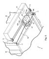
figure 3 est une vue simplifiée et éclatée d'un demi-wagon selon l'invention ; - la
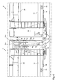
figure 4 est une vue schématique de dessous d'un treuil selon l'invention monté sur un wagon ; - la
figure 5 est une vue schématique d'un treuil selon un montage différent sur un wagon ; - la
figure 6 est une vue de détail correspondant au détail VI sur lafigure 1 ; et - la
figure 7 est une vue de dessus d'un treuil selon l'invention.
- the
figure 1 is a side view of a portion of a wagon train according to the invention in the transport position; - the
figure 2 is a side view of the same wagon train portion according to the invention, in the loading position; - the
figure 3 is a simplified and exploded view of a half-car according to the invention; - the
figure 4 is a schematic bottom view of a winch according to the invention mounted on a wagon; - the
figure 5 is a schematic view of a winch in a different arrangement on a wagon; - the
figure 6 is a detail view corresponding to detail VI on thefigure 1 ; and - the
figure 7 is a top view of a winch according to the invention.
Comme visible en
Chaque demi-wagon 2 est pourvu d'un pont inférieur 10 et d'un pont supérieur 20. Le pont supérieur 20 est monté à coulissement dans quatre montants 30, de manière à être entièrement mobile par rapport au pont inférieur 10. Chacun des montants 30 est pourvu de moyens permettant de manoeuvrer l'extrémité correspondante du pont supérieur 20. Plus particulièrement, chacun des montants 30 présente un système à câble et poulie, le câble étant enroulé sur le tambour 41 d'un treuil 40 fixé sous le plancher inférieur 10 du demi-wagon 2, et manoeuvrable depuis le sol.Each half-
Ainsi, deux paires de montants équipés de la sorte et situés face à face à une extrémité du demi-wagon, permettent de commander la montée et la descente de chaque extrémité du pont supérieur 20 indépendamment. Cette disposition permet d'incliner le pont par rapport à l'horizontale lorsque cela est nécessaire, par exemple pour le chargement ou le déchargement du train de wagons.Thus, two pairs of amounts equipped in this way and located face to face at one end of the half-wagon, can control the rise and fall of each end of the
Comme visible plus particulièrement en
Les deux extrémités correspondantes des deux ponts supérieurs correspondants sont alors surélevées à l'aide des moyens se trouvant dans les montants 30 de manière à laisser un espace en hauteur suffisant pour permettre aux véhicules de passer sur les ponts provisoires 11.The two corresponding ends of the two corresponding upper decks are then raised using the means in the
La
Chacun des montants 30 est pourvu d'une portion de câble permettant de manoeuvrer le pont supérieur 20. Chaque paire de montants 30 se trouvant respectivement à chaque extrémité d'un demi-wagon 2 coopère avec un treuil 40 à enroulement de câble fixé sous le pont inférieur 10. Les portions de câbles 51, 52, 53, 54 sont dessinés de manière schématique en
Chaque paire de montants se trouvant à l'extrémité d'un demi-wagon est également pourvue d'un mécanisme anti-retour débrayable 60 représenté très schématiquement en
Chaque montant présente une portion de câble dont une extrémité est enroulée sur un tambour 41 de treuil 40 et dont l'extrémité opposée est reliée à un tendeur 55 fixé sur le montant 30, pour maintenir la tension du câble constante, et éviter l'apparition d'un mou trop important lorsque le câble est totalement déroulé.Each upright has a cable portion of which one end is wound on a
En pratique, le tendeur est constitué d'une masselotte pesant de 30 à 40 kg environ, arrimée à l'extrémité du câble et coulissant autour d'un pion 56 fixé sur le montant, comme visible en
Comme visible plus particulièrement en
Chacune des portions de câble 51 et 52 est respectivement guidée vers le montant 30 correspondant par des poulies 14 horizontales puis verticales 13 disposées sous le pont inférieur 10 du demi-wagon 2.Each of the
Le treuil 40 présente un premier arbre d'entrée de force 42 et un second arbre d'entrée de force 43 qui débouche de part et d'autre du boitier du treuil respectivement sous forme de sortie 42A, 42B et 43A, 43B. Des arbres 12A, 12B et 13A, 13B sont respectivement reliés à ces sorties 42A, 42B et 43A, 43B de manière à permettre la manoeuvre de chacun des deux arbres d'entrée de force depuis l'un ou l'autre des côtés du wagon. Des plaques support 15 sont prévues de part et d'autre du wagon sous le plancher inférieur 10 de manière à supporter les extrémités des arbres 12A, 13A et 12B, 13B. Les plaques 15 sont disposées sur le wagon de manière à se situer à hauteur d'homme depuis le sol pour permettre de manoeuvrer aisément les deux arbres d'entrée. Comme visibles sur les
Le treuil situé à l'autre extrémité du demi-wagon 2 visible en
On notera que le cheminement des câbles 53 et 54 suit chacun un itinéraire imposé par une poulie de renvoi verticale permettant de renvoyer le câble directement dans le montant 30 correspondant.It will be noted that the routing of the
Chaque montant présente deux tubes 32A, 32B sur lesquels est montée, à translation, une traverse 33, qui peut se mouvoir le long des tubes à la manière d'un coulisseau.Each upright has two tubes 32A, 32B on which is mounted, in translation, a
Le pont supérieur mobile repose sur quatre de ces traverses, situées, dans les montants, aux quatre coins du pont supérieur en question.The movable upper deck rests on four of these sleepers, located in the uprights at the four corners of the upper deck in question.
Comme indiqué supra, un système à câble et poulie est prévu dans chacun des montants de manière à assurer la manoeuvre du pont supérieur correspondant. A la symétrie près, tous ces systèmes à câble et poulie sont identiques, c'est pourquoi un seul de ces systèmes sera décrit ici en détail.As indicated above, a cable and pulley system is provided in each of the uprights so as to ensure the operation of the corresponding upper deck. To the symmetry, all these cable and pulley systems are identical, which is why only one of these systems will be described here in detail.
Un tel système à câble et poulie est visible en détail plus particulièrement en
Deux poulies identiques 31A et 31B sont disposées dans la partie supérieure du montant, une poulie 21 étant installée sur la tranche de la traverse 33 soutenant le pont supérieur, chacune de ces poulies ayant une gorge prévue pour coopérer avec le câble 51 qui y est installé. Le câble 51 descend dans la partie inférieure du montant et suit le cheminement imposé par une poulie verticale 13 et une poulie horizontale 14 jusqu'à atteindre le tambour 41 du treuil 40 tel que visible en
En pratique, lorsque le câble est enroulé sur le tambour 41 du treuil 40, les poulies 31A et 31 B se rapprochent de la poulie 21 déplaçant ainsi le pont 20 vers le haut. Pour déplacer le pont vers le bas, il est nécessaire de débrayer le mécanisme anti-retour en actionnant la poignée 64 de manière à dégager la crémaillère 61 du cliquet 62 en permettant ainsi la descente du pont 20 en déroulant le câble 51 depuis le treuil 40. Le tendeur 55 permet d'assurer une tension permanente du câble, y compris en fin de course, notamment pour éviter que le câble sorte des gorges prévues dans les poulies 31A, 31 B et 21.In practice, when the cable is wound on the
Nous allons maintenant décrire plus en détail un treuil 40 visible en
Chacun des demi-wagons est pourvu de deux treuils 40 identiques.Each of the half-wagons is provided with two
Chacun des treuils 40 présente un premier arbre d'entrée de force 42 et un second arbre d'entrée de force 43. Des moyens de démultiplication sont interposés entre le tambour 41 et le premier arbre 42. Ces moyens de démultiplication sont constitués par une roue dentée 411 disposée à une extrémité du tambour et solidaire en rotation avec celui-ci, engrenant avec un pignon 412 disposé solidaire en rotation sur un arbre 413 monté à rotation dans le bâti 44 de manière parallèle au tambour 41. L'arbre 413 à l'extrémité opposée au pignon 412, est solidaire en rotation d'une couronne 414 conique. La couronne 414 engrène avec un pignon conique de manière à former un couple conique 416. Le pignon 415 est monté sur le premier arbre d'entrée 42, monté à rotation dans le bâti 44 perpendiculairement au tambour 41.Each of the
Des moyens de démultiplication supplémentaires sont prévus entre le premier et le second arbre d'entrée. Ces moyens sont constitués d'une roue dentée 417 montée solidaire en rotation sur l'arbre 42 et d'un pignon 418 monté solidaire en rotation sur le second arbre d'entrée de force 43, lui-même monté à rotation dans le bâti 44 parallèlement à l'arbre 42. La roue dentée 417 et le pignon 418 sont reliés l'un à l'autre par une chaîne duplex 419 assurant la liaison mécanique en rotation des arbres 42 et 43.Additional gearing means are provided between the first and second input shaft. These means consist of a
Le treuil 40 comporte en outre un mécanisme d'irréversibilité en enroulement de câble pour le tambour, qui est débrayable en déroulement de câble au profit d'un mécanisme de retenue de charge. Le mécanisme d'irréversibilité comporte une roue à rochet 420 coopérant avec un cliquet 421 et contraint vers le rochet par un ressort de rappel 422. Le mécanisme d'irréversibilité et de retenue de charge comporte en outre un arbre creux 423 monté solidaire en rotation sur le premier arbre d'entrée 42, et ayant à l'une de ses extrémités, un épaulement 424 et à son extrémité opposée une portée filetée de manière à y monter le pignon conique 415 en liaison hélicoïdale. Le pignon conique 415 est taraudé à cet effet. Cette liaison hélicoïdale est schématiquement représentée sur la
Avantageusement, la roue à rochet est réalisée en alliage de cuivre de manière à limiter son usure prématurée, notamment à cause de la chaleur due au frottement entre le pignon et l'épaulement. De manière particulièrement avantageuse, l'alliage de cuivre comporte, en poids, 10 % d'étain et 10 % de plomb, ce qui permet d'optimiser les performances de la roue à rochet, notamment de lui permettre de conserver son coefficient de frottement malgré son échauffement.Advantageously, the ratchet wheel is made of copper alloy so as to limit its premature wear, particularly because of the heat due to friction between the pinion and the shoulder. In a particularly advantageous manner, the copper alloy comprises, by weight, 10% tin and 10% lead, which makes it possible to optimize the performance of the ratchet wheel, in particular to enable it to maintain its coefficient of friction. despite his warm up.
En pratique, les démultiplications prévues entre l'arbre 42 et le treuil 41 sont dimensionnées, d'une part, pour actionner manuellement un pont à vide et, d'autre part, pour actionner un pont chargé à l'aide de moyens motorisés. L'arbre d'entrée 43, en revanche, est dimensionné pour permettre la manoeuvre d'un pont chargé manuellement à l'aide d'une manivelle (non représentée). Ces démultiplications sont conçues de manière à permettre des ponts de manoeuvre de pont, en particulier des manoeuvres de pont chargées à l'aide d'une manivelle via l'arbre 43, dans un temps suffisamment réduit pour assurer un chargement et un déchargement rapide du train de wagon porte-véhicules.In practice, the gear ratios provided between the
Plus particulièrement, le rapport de démultiplication est choisi de manière à ce que vingt-quatre tours de manivelle (non représentée) soient suffisants pour obtenir un tour de tambour 41.More particularly, the gear ratio is chosen so that twenty-four crank turns (not shown) are sufficient to obtain a
Les moyens de démultiplication prévus entre l'arbre 42 et le tambour 41 sont dimensionnés de manière à permettre une manipulation particulièrement rapide d'un pont à vide à l'aide d'une manivelle.The reduction means provided between the
Dans un mode de réalisation non représenté, le cliquet 421 est doublé par un second cliquet disposé sur la même roue à rochet 420 par mesure de sécurité. Le second cliquet est également pourvu de moyens de rappel, par exemple un ressort similaire au ressort 422, contraignant le cliquet vers la roue à rochet. De plus, le second cliquet est disposé de manière à ce que, en cas de défaillance des moyens de rappel, de par la gravité et son propre poids, coopère par interférence de formes avec la roue à rochet de manière à assurer l'irréversibilité du mécanisme.In an embodiment not shown, the
II en va de même pour le treuil 40, identique, sur le tambour duquel sont enroulées les portions de câble 54 et 53 visibles en
De nombreuses autres variantes sont possibles en fonction des circonstances, et l'on rappelle à cet égard que l'invention ne se limite pas aux exemples décrits et représentés.Many other variants are possible depending on the circumstances, and it is recalled in this regard that the invention is not limited to the examples described and shown.
Claims (19)
Applications Claiming Priority (1)
| Application Number | Priority Date | Filing Date | Title |
|---|---|---|---|
| FR0754218A FR2914263B1 (en) | 2007-04-02 | 2007-04-02 | WINCH FOR WAGON VEHICLE CARRIER AND WAGON COMPRISING THE SAME |
Publications (1)
| Publication Number | Publication Date |
|---|---|
| EP1977988A1 true EP1977988A1 (en) | 2008-10-08 |
Family
ID=38885106
Family Applications (1)
| Application Number | Title | Priority Date | Filing Date |
|---|---|---|---|
| EP08290308A Withdrawn EP1977988A1 (en) | 2007-04-02 | 2008-03-31 | Winch for vehicle transport carriage and carriage comprising same |
Country Status (2)
| Country | Link |
|---|---|
| EP (1) | EP1977988A1 (en) |
| FR (1) | FR2914263B1 (en) |
Families Citing this family (1)
| Publication number | Priority date | Publication date | Assignee | Title |
|---|---|---|---|---|
| FR2937299B1 (en) * | 2008-10-17 | 2010-11-26 | R F Ind Sa Ab | WAGON FOR THE TRANSPORT OF MOTOR VEHICLES |
Citations (6)
| Publication number | Priority date | Publication date | Assignee | Title |
|---|---|---|---|---|
| DE473276C (en) * | 1926-07-17 | 1929-03-13 | Johannes Burmester & Co Maschi | Hand crank secured against kickback and usable as a braking device |
| US2224503A (en) | 1936-07-23 | 1940-12-10 | Mckiernan Terry Corp | Boat winch |
| GB678466A (en) * | 1950-03-23 | 1952-09-03 | Wharton Crane & Hoist Co Ltd | Improvements in electrically driven winches |
| US3667312A (en) * | 1971-01-11 | 1972-06-06 | Howard C Dahl | Drive reduction mechanism |
| DE2159289A1 (en) * | 1970-12-02 | 1972-06-22 | Dutton Lainson Co | Drive device for winches |
| EP0042801A1 (en) * | 1980-06-19 | 1981-12-30 | Etablissements Huchez & Cie | Security device for a geared transmission |
Family Cites Families (4)
| Publication number | Priority date | Publication date | Assignee | Title |
|---|---|---|---|---|
| GB404158A (en) * | 1932-07-13 | 1934-01-11 | Clarke Chapman Ltd | Improvements in and relating to ships derricks and cargo working machinery |
| GB801252A (en) * | 1955-10-04 | 1958-09-10 | Charles Cooke Ltd | Improvements in power driven winches |
| GB1505244A (en) * | 1975-10-10 | 1978-03-30 | Gen Electric | Winches for use with high masts |
| US4625946A (en) * | 1984-03-19 | 1986-12-02 | Ederer Incorporated | Hoist having worm safety device |
-
2007
- 2007-04-02 FR FR0754218A patent/FR2914263B1/en not_active Expired - Fee Related
-
2008
- 2008-03-31 EP EP08290308A patent/EP1977988A1/en not_active Withdrawn
Patent Citations (6)
| Publication number | Priority date | Publication date | Assignee | Title |
|---|---|---|---|---|
| DE473276C (en) * | 1926-07-17 | 1929-03-13 | Johannes Burmester & Co Maschi | Hand crank secured against kickback and usable as a braking device |
| US2224503A (en) | 1936-07-23 | 1940-12-10 | Mckiernan Terry Corp | Boat winch |
| GB678466A (en) * | 1950-03-23 | 1952-09-03 | Wharton Crane & Hoist Co Ltd | Improvements in electrically driven winches |
| DE2159289A1 (en) * | 1970-12-02 | 1972-06-22 | Dutton Lainson Co | Drive device for winches |
| US3667312A (en) * | 1971-01-11 | 1972-06-06 | Howard C Dahl | Drive reduction mechanism |
| EP0042801A1 (en) * | 1980-06-19 | 1981-12-30 | Etablissements Huchez & Cie | Security device for a geared transmission |
Also Published As
| Publication number | Publication date |
|---|---|
| FR2914263A1 (en) | 2008-10-03 |
| FR2914263B1 (en) | 2010-03-12 |
Similar Documents
| Publication | Publication Date | Title |
|---|---|---|
| EP2028074B1 (en) | Vehicle for conducting repairs along an overhead cable of a rope railway | |
| EP0199652A1 (en) | Container-handling device | |
| EP1476343B1 (en) | Hand truck materials handling device | |
| WO2013054012A1 (en) | Apparatus for towing a motor vehicle | |
| EP1977988A1 (en) | Winch for vehicle transport carriage and carriage comprising same | |
| EP4063192B1 (en) | Vehicle for transporting loads comprising an assembly for moving a load | |
| EP2252493B1 (en) | Car for handling heavy loads, in particular rails, and use of said car in the presence of a catenary system | |
| EP3687856B1 (en) | Loading platform for a car with sliding crossmember of basket type | |
| WO2007113441A2 (en) | Lifting vehicle for goods and persons working at height | |
| EP3347668B1 (en) | Device for transporting a torpedo from a transport carriage to a launching tube | |
| FR2644196A1 (en) | Method and device for handling a vehicle in a car park installation | |
| FR2908092A1 (en) | Heavy object e.g. motor cycle, loading and unloading device for e.g. trailer, has guiding unit guiding ramp between two positions and bringing back ramp above floor, when ramp reaches loading/unloading position | |
| WO2013139689A1 (en) | Pulling system for a vehicle and method for ensuring the safe pulling of a vehicle over the ground | |
| FR2527155A1 (en) | Trolley for use on stairs - has feeler which controls pawl braking on carrying wheels | |
| WO2023099821A1 (en) | Improved winch device for a wheelchair | |
| EP0062342A1 (en) | Quick loading apparatus for transport vehicles, especially for trucks | |
| FR3029512A1 (en) | LIGHT HANDLING APPARATUS | |
| EP1827903B1 (en) | Transport trailer capable of being loaded and unloaded by means of a truck equipped with a gripping arm | |
| CH291892A (en) | Lifting device for motor vehicles. | |
| EP0112735A1 (en) | Auxiliary manual drive for trailers, especially for caravans | |
| FR2970719A1 (en) | Gantry for passage of firefighter lorry, has movable cross-piece carried by single post and hinge arranged between cross-piece and carriage, where rotation of cross-piece is limited by spring exerting force opposite to cross-piece rotation | |
| FR3079194A1 (en) | DEVICE FOR DRIVING TENSION CABLES OF AT LEAST ONE VEHICLE ON AN INCLINED OR VERTICAL TRACK AND PASSENGER TRANSPORTATION EQUIPPED WITH SUCH A DEVICE | |
| FR2970718A1 (en) | Elastic lifting gantry for use in parking to allow passage of fire truck, has elastic unit exerting forces on carriage, and compressing unit to compress elastic unit for moving cross-piece towards downwardly | |
| FR2606004A1 (en) | System for vertical handling and towing of standardised containers | |
| FR2727100A1 (en) | Telescopic leg support system for lorry container |
Legal Events
| Date | Code | Title | Description |
|---|---|---|---|
| PUAI | Public reference made under article 153(3) epc to a published international application that has entered the european phase |
Free format text: ORIGINAL CODE: 0009012 |
|
| AK | Designated contracting states |
Kind code of ref document: A1 Designated state(s): AT BE BG CH CY CZ DE DK EE ES FI FR GB GR HR HU IE IS IT LI LT LU LV MC MT NL NO PL PT RO SE SI SK TR |
|
| AX | Request for extension of the european patent |
Extension state: AL BA MK RS |
|
| 17P | Request for examination filed |
Effective date: 20090403 |
|
| 17Q | First examination report despatched |
Effective date: 20090512 |
|
| AKX | Designation fees paid |
Designated state(s): AT BE BG CH CY CZ DE DK EE ES FI FR GB GR HR HU IE IS IT LI LT LU LV MC MT NL NO PL PT RO SE SI SK TR |
|
| GRAP | Despatch of communication of intention to grant a patent |
Free format text: ORIGINAL CODE: EPIDOSNIGR1 |
|
| GRAS | Grant fee paid |
Free format text: ORIGINAL CODE: EPIDOSNIGR3 |
|
| STAA | Information on the status of an ep patent application or granted ep patent |
Free format text: STATUS: THE APPLICATION IS DEEMED TO BE WITHDRAWN |
|
| 18D | Application deemed to be withdrawn |
Effective date: 20101116 |