EP1977193B1 - Isolateur pour systeme de capteur d'une machine d'usinage au laser - Google Patents
Isolateur pour systeme de capteur d'une machine d'usinage au laser Download PDFInfo
- Publication number
- EP1977193B1 EP1977193B1 EP05817911.0A EP05817911A EP1977193B1 EP 1977193 B1 EP1977193 B1 EP 1977193B1 EP 05817911 A EP05817911 A EP 05817911A EP 1977193 B1 EP1977193 B1 EP 1977193B1
- Authority
- EP
- European Patent Office
- Prior art keywords
- laser processing
- processing machine
- shielding part
- sensor arrangement
- insulator
- Prior art date
- Legal status (The legal status is an assumption and is not a legal conclusion. Google has not performed a legal analysis and makes no representation as to the accuracy of the status listed.)
- Not-in-force
Links
Images

Classifications
-
- B—PERFORMING OPERATIONS; TRANSPORTING
- B23—MACHINE TOOLS; METAL-WORKING NOT OTHERWISE PROVIDED FOR
- B23K—SOLDERING OR UNSOLDERING; WELDING; CLADDING OR PLATING BY SOLDERING OR WELDING; CUTTING BY APPLYING HEAT LOCALLY, e.g. FLAME CUTTING; WORKING BY LASER BEAM
- B23K26/00—Working by laser beam, e.g. welding, cutting or boring
- B23K26/02—Positioning or observing the workpiece, e.g. with respect to the point of impact; Aligning, aiming or focusing the laser beam
- B23K26/04—Automatically aligning, aiming or focusing the laser beam, e.g. using the back-scattered light
- B23K26/046—Automatically focusing the laser beam
- B23K26/048—Automatically focusing the laser beam by controlling the distance between laser head and workpiece
-
- Y—GENERAL TAGGING OF NEW TECHNOLOGICAL DEVELOPMENTS; GENERAL TAGGING OF CROSS-SECTIONAL TECHNOLOGIES SPANNING OVER SEVERAL SECTIONS OF THE IPC; TECHNICAL SUBJECTS COVERED BY FORMER USPC CROSS-REFERENCE ART COLLECTIONS [XRACs] AND DIGESTS
- Y10—TECHNICAL SUBJECTS COVERED BY FORMER USPC
- Y10T—TECHNICAL SUBJECTS COVERED BY FORMER US CLASSIFICATION
- Y10T428/00—Stock material or miscellaneous articles
- Y10T428/26—Web or sheet containing structurally defined element or component, the element or component having a specified physical dimension
Definitions
- the present invention relates to a laser processing machine with a sensor arrangement according to the preamble of claim 1.
- the DE 4 035 404 A1 discloses such a laser processing machine.
- a sensor arrangement is, for example, by the DE 199 06 442 A1 known. Isolators are part of sensor arrays and have become known through their use in commercially available laser processing machines.
- insulators are made of ceramic, such as Al 2 O 3 , which has a high resistance to heat and shock, but due to its hardness is difficult to work.
- the capacitive resistance is more important than the insulation from direct current. Therefore, the isolation distance must be large for an insulator made of Al 2 O 3 .
- the insulator is struck when cutting diffused back-reflected radiation. Therefore, it is further required that the insulator is made of a material which is not destroyed or damaged by the reverberation.
- Al 2 O 3 is ideal for this purpose Properties, as it is very resistant to heat and shock.
- the prior art nozzle has a conical nozzle body with a brass tip portion located toward the workpiece and with a surface anodized and thus electrically non-conductive remaining portion on the side of the tip portion remote from the workpiece.
- the nozzle body is acted upon by a clamping element.
- This has a z. B. made of steel inner body and the inner body enclosing outer body made of electrically insulating material.
- the inner body of the clamping element is supported on the remaining area of the conical nozzle body at the end face remote from the tip area of the conical nozzle body.
- the remaining area of the conical nozzle body is offset from the electrically insulating outer body of the clamping element towards the workpiece.
- the remaining portion of the conical nozzle body and the outer body of the clamping member are parts of an insulator, by means of which a workpiece-side nozzle electrode of the prior art nozzle against the remaining material processing device, in which the nozzle is screwed, is electrically insulated.
- the invention has for its object to provide a laser processing machine with a simple and inexpensive to manufacture sensor array.
- the outer isolator is made of plastic and serves for electrical insulation.
- the inner Ableungstell consists of a non-conductive and heat-resistant material such. As quartz glass and is intended to shield against the above-mentioned reflection.
- the Ableungstell can be formed as a quartz glass tube or as a ceramic sleeve and glued or pressed into the insulating part.
- the insulating member can be made inexpensively from a plastic and easily manufactured.
- the shielding part serves to shield against the laser radiation.
- the shielding member is capable of withstanding higher laser powers without reflow or other damage.
- the exact fit of the shield can be accomplished by rotating the plastic part instead of time consuming grinding of the ceramic. The burning process of the ceramic can be saved.
- the shielding part may preferably consist of a quartz glass tube. Quartz has a very high thermal shock resistance and is inexpensive to manufacture.
- the shielding member may also be made of ceramic, eg Al 2 O 3 .
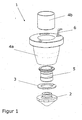
- FIGS. 1 and 2 shows the construction of a sensor arrangement 1 of a laser processing machine, which is suitable for the thermal cutting of workpieces by means of laser radiation.
- the sensor arrangement 1 essentially comprises a laser processing nozzle 2, a contact disk 3, a nozzle receptacle 5, a two-part insulator (an insulating part 4a for electrical insulation and a shielding part 4b for shielding against radiation and / or heat) and a contact pin 6.
- the nozzle receptacle 5 serves to attach the laser processing nozzle 2 to the insulating part 4a.
- the invention consists in designing the two-part insulator used in the sensor arrangement 1 such that the inner shielding part 4b is arranged on the inside of the outer insulation part 4a.
- the outer part 4a used for electrical insulation consists of a suitable plastic with low capacitance ⁇ r and high softening temperature.
- the stray radiation protection on the Inner side of the part 4a is configured by a pressed-in (or glued) quartz glass tube 4b.
- a shield is necessary as a radiation shield, which protects the part 4a from reflected laser radiation or from excessive thermal radiation which destroys the part 4a.
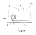
- the per se known and therefore not described in detail here measuring principle for the distance control of the laser machining nozzle 2 with respect to the workpiece is based according to FIG. 3 on the measurement of the electrical capacitance between the laser machining nozzle 2 and a workpiece 7.
- the capacitance is distance-dependent and decreases with increasing distance of the laser machining nozzle 2 to the workpiece 7.
- the capacitance measurement is carried out by means of a measuring device 10 based on a resonant circuit whose frequency is detuned capacitance-dependent , The relationship between the distance and the frequency is established using a characteristic curve determined at intervals.
- the distance-dependent signal is detected by the measuring device 10.
- Such a distance control is, for example, by the DE19906442 known.
- An integrated in the lower part of the laser processing head RF oscillator changes its frequency as a function of Measuring distance.
- the frequency signal is first transmitted to an evaluation unit 9 and evaluated digitally.
- the distance is determined via a previously recorded characteristic from the frequency.
- the laser processing nozzle 2 can follow the contour of the workpiece surface. Collisions between the laser processing head and the workpiece 7 are avoided.
- the position of the workpiece 7 can be determined with the distance control, so that subsequent displacement is omitted for precise alignment.
Claims (6)
- Machine d'usinage par laser comportant un dispositif capteur qui comprend un isolateur qui présente une pièce isolante extérieure (4a) en matière plastique pour le blindage électrique et une pièce de blindage intérieure (4b) dans un matériau non conducteur résistant à la chaleur, caractérisée en ce que la pièce isolante extérieure (4a) peut être protégée contre le rayonnement laser réfléchi et/ou la chaleur par la pièce de blindage intérieure (4b) du fait que la pièce de blindage intérieure (4b) est disposée sur le côté intérieur de la pièce isolante extérieure (4a).
- Machine d'usinage par laser selon la revendication 1, caractérisée en ce que la pièce de blindage (4b) est constituée de verre de quartz.
- Machine d'usinage par laser selon la revendication 1, caractérisée en ce que la pièce de blindage (4b) est constituée d'une céramique.
- Machine d'usinage par laser selon l'une des revendications précédentes, caractérisée en ce que la pièce de blindage (4b) est réalisée en forme de tube.
- Machine d'usinage par laser selon l'une des revendications précédentes, caractérisée en ce que la pièce de blindage (4b) est collée.
- Machine d'usinage par laser selon l'une des revendications précédentes, caractérisée en ce que la pièce de blindage (4b) est emmanchée.
Applications Claiming Priority (1)
| Application Number | Priority Date | Filing Date | Title |
|---|---|---|---|
| PCT/EP2005/013560 WO2007073745A1 (fr) | 2005-12-16 | 2005-12-16 | Isolateur pour systeme de capteur d'une machine d'usinage au laser |
Publications (2)
| Publication Number | Publication Date |
|---|---|
| EP1977193A1 EP1977193A1 (fr) | 2008-10-08 |
| EP1977193B1 true EP1977193B1 (fr) | 2015-09-02 |
Family
ID=36794418
Family Applications (1)
| Application Number | Title | Priority Date | Filing Date |
|---|---|---|---|
| EP05817911.0A Not-in-force EP1977193B1 (fr) | 2005-12-16 | 2005-12-16 | Isolateur pour systeme de capteur d'une machine d'usinage au laser |
Country Status (5)
| Country | Link |
|---|---|
| US (1) | US8247732B2 (fr) |
| EP (1) | EP1977193B1 (fr) |
| JP (1) | JP5074412B2 (fr) |
| CN (1) | CN101326426B (fr) |
| WO (1) | WO2007073745A1 (fr) |
Cited By (2)
| Publication number | Priority date | Publication date | Assignee | Title |
|---|---|---|---|---|
| DE102016113950A1 (de) * | 2016-07-28 | 2018-02-01 | HELLA GmbH & Co. KGaA | Fügeverfahren und Fügeeinrichtung zur Durchführung des Fügeverfahrens |
| WO2018033372A1 (fr) | 2016-08-19 | 2018-02-22 | Precitec Gmbh & Co. Kg | Élément isolant pour le montage isolant d'une buse électriquement conductrice et tête d'usinage au laser muni d'un dispositif de détection pour détecter un tel élément isolant |
Families Citing this family (10)
| Publication number | Priority date | Publication date | Assignee | Title |
|---|---|---|---|---|
| JP4858966B2 (ja) | 2006-11-02 | 2012-01-18 | Towa株式会社 | 電子部品の圧縮成形方法及び成形装置 |
| EP2444193A1 (fr) | 2010-10-20 | 2012-04-25 | Bystronic Laser AG | Tête de traitement au laser avec une partie extérieure isolante et une partie intérieure isolante en métal |
| EP2468449B1 (fr) * | 2010-12-21 | 2015-01-28 | TRUMPF Werkzeugmaschinen GmbH + Co. KG | Dispositif et procédé destinés à la protection contre un rayon laser sur une machine de traitement par laser destinée à traiter des pièces avec des moyens pour estimer l'orientation de la surface d'appui de l'organe de protection |
| US10220472B2 (en) * | 2014-01-30 | 2019-03-05 | Lasx Industries, Inc | Modeling of laser output from a pulsed laser to achieve a consistent cutting process |
| ES2577864B1 (es) * | 2015-01-16 | 2017-04-28 | Indra Sistemas, S.A. | Equipo para el análisis de residuos de disparos, métodos para la determinación de la presencia de residuos de disparo y método para determinar la distancia de disparo |
| RU2714596C2 (ru) * | 2017-05-25 | 2020-02-18 | Общество с ограниченной ответственностью Научно-производственный центр "Лазеры и аппаратура ТМ" | Устройство для управления положением лазерной головки относительно обрабатываемой поверхности |
| RU178434U1 (ru) * | 2017-05-25 | 2018-04-04 | Общество с ограниченной ответственностью Научно-производственный центр "Лазеры и аппаратура ТМ" | Устройство для управления положением лазерной головки относительно обрабатываемой поверхности |
| DE102017214249A1 (de) * | 2017-08-16 | 2019-02-21 | Trumpf Werkzeugmaschinen Gmbh + Co. Kg | Laserbearbeitungskopf mit einem optischen Element zum Herausfiltern von UV-Prozessstrahlung und zugehöriges Laserbearbeitungsverfahren |
| CN109530942A (zh) * | 2018-12-13 | 2019-03-29 | 广东天丰精密技术有限公司 | 一种激光喷嘴连接装置 |
| RU208403U1 (ru) * | 2021-06-03 | 2021-12-16 | федеральное государственное бюджетное образовательное учреждение высшего образования "Первый Санкт-Петербургский государственный медицинский университет имени академика И.П. Павлова" Министерства здравоохранения Российской Федерации | Насадка для защиты от лазерного воздействия струйного катетера для искусственной вентиляции легких при лазерной хирургии гортани и трахеи |
Citations (1)
| Publication number | Priority date | Publication date | Assignee | Title |
|---|---|---|---|---|
| JPH09277080A (ja) * | 1996-04-19 | 1997-10-28 | Hino Motors Ltd | レーザビーム加工機のレーザノズル |
Family Cites Families (16)
| Publication number | Priority date | Publication date | Assignee | Title |
|---|---|---|---|---|
| US2313889A (en) * | 1941-08-22 | 1943-03-16 | Fischer & Porter Co | Rotameter and the like |
| US3233076A (en) * | 1964-09-21 | 1966-02-01 | Welding Research Inc | Welding control system |
| IT1179924B (it) * | 1984-05-22 | 1987-09-16 | Prima Progetti Spa | Testa focalizzatrice per una macchina da taglio a raggi laser |
| US5031984A (en) * | 1990-01-17 | 1991-07-16 | Alcatel Na | Optical fiber electro-optical module |
| DE4028338A1 (de) * | 1990-09-06 | 1992-03-12 | Weidmueller C A Gmbh Co | Duese fuer ein werkzeug zur materialbearbeitung |
| US5500504A (en) * | 1990-11-07 | 1996-03-19 | C. A. Weidmuller Gmbh & Co. | Nozzle for a tool for the working of material |
| DE4035404A1 (de) * | 1990-11-07 | 1992-05-14 | Weidmueller C A Gmbh Co | Duese fuer ein werkzeug zur materialbearbeitung |
| DE4108542A1 (de) * | 1991-03-15 | 1992-09-17 | Linde Ag | Verfahren zum laserschneiden und laserschneidkopf |
| US5438187A (en) * | 1991-11-01 | 1995-08-01 | Spectra-Physics Scanning Systems, Inc. | Multiple focus optical system for data reading applications |
| CA2091512A1 (fr) * | 1992-03-13 | 1993-09-14 | Kohichi Haruta | Buse d'irradiation laser et laser utilisant cette buse |
| JP3628437B2 (ja) * | 1996-06-04 | 2005-03-09 | 株式会社アマダ | レーザー加工機のレーザービーム保護カバー |
| JP2000202676A (ja) * | 1999-01-14 | 2000-07-25 | Mitsubishi Heavy Ind Ltd | レ―ザ加工ヘッド |
| DE19906442C2 (de) | 1999-02-16 | 2001-10-18 | Precitec Kg | Verfahren zum Messen des Abstandes zwischen einer Sensorelektrode und einem Werkstück |
| US6620333B2 (en) * | 2000-10-23 | 2003-09-16 | The Regents Of The University Of California | CO2 laser and plasma microjet process for improving laser optics |
| US6852981B2 (en) * | 2002-11-04 | 2005-02-08 | Vladimir A Danilychev | Ultraviolet radiation intensity meter |
| JP4182044B2 (ja) * | 2004-10-14 | 2008-11-19 | ファナック株式会社 | レーザ加工装置 |
-
2005
- 2005-12-16 EP EP05817911.0A patent/EP1977193B1/fr not_active Not-in-force
- 2005-12-16 CN CN200580052296.0A patent/CN101326426B/zh not_active Expired - Fee Related
- 2005-12-16 WO PCT/EP2005/013560 patent/WO2007073745A1/fr active Application Filing
- 2005-12-16 JP JP2008544766A patent/JP5074412B2/ja not_active Expired - Fee Related
-
2008
- 2008-06-11 US US12/136,912 patent/US8247732B2/en active Active
Patent Citations (1)
| Publication number | Priority date | Publication date | Assignee | Title |
|---|---|---|---|---|
| JPH09277080A (ja) * | 1996-04-19 | 1997-10-28 | Hino Motors Ltd | レーザビーム加工機のレーザノズル |
Cited By (5)
| Publication number | Priority date | Publication date | Assignee | Title |
|---|---|---|---|---|
| DE102016113950A1 (de) * | 2016-07-28 | 2018-02-01 | HELLA GmbH & Co. KGaA | Fügeverfahren und Fügeeinrichtung zur Durchführung des Fügeverfahrens |
| WO2018033372A1 (fr) | 2016-08-19 | 2018-02-22 | Precitec Gmbh & Co. Kg | Élément isolant pour le montage isolant d'une buse électriquement conductrice et tête d'usinage au laser muni d'un dispositif de détection pour détecter un tel élément isolant |
| DE102016115415A1 (de) * | 2016-08-19 | 2018-02-22 | Precitec Gmbh & Co. Kg | Isolationsteil zur isolierten Halterung einer elektrisch leitenden Düse und Laserbearbeitungskopf mit einem Sensor zur Erkennung eines derartigen Isolationsteils |
| DE102016115415B4 (de) * | 2016-08-19 | 2018-04-12 | Precitec Gmbh & Co. Kg | Isolationsteil zur isolierten Halterung einer elektrisch leitenden Düse und Laserbearbeitungskopf mit einem Sensor zur Erkennung eines derartigen Isolationsteils |
| US11446758B2 (en) | 2016-08-19 | 2022-09-20 | Precitec Gmbh & Co. Kg | Insulation part and laser machining head with insulation part detecting sensor |
Also Published As
| Publication number | Publication date |
|---|---|
| EP1977193A1 (fr) | 2008-10-08 |
| US8247732B2 (en) | 2012-08-21 |
| CN101326426B (zh) | 2012-12-05 |
| WO2007073745A1 (fr) | 2007-07-05 |
| JP2009519133A (ja) | 2009-05-14 |
| US20080264914A1 (en) | 2008-10-30 |
| CN101326426A (zh) | 2008-12-17 |
| JP5074412B2 (ja) | 2012-11-14 |
Similar Documents
| Publication | Publication Date | Title |
|---|---|---|
| EP1977193B1 (fr) | Isolateur pour systeme de capteur d'une machine d'usinage au laser | |
| EP0226047B1 (fr) | Electrode immergée pour la lithotripsy sans contact | |
| EP1856497B1 (fr) | Composant pour capteurs de force ou de pression, dont les elements sont maintenus les uns avec les autres par un film electro-isolant | |
| DE102011006907B4 (de) | Wälzkörper | |
| DE2449673A1 (de) | Direktberuehrende messlehre fuer das ausmessen bewegter werkstuecke mit mindestens einem fuehler | |
| EP0730160A2 (fr) | Dispositif de mesure de décharge partielle | |
| EP0864888A1 (fr) | Connecteur pour une connexion enfichable optique et procédé pour sa fabrication | |
| EP3447858B1 (fr) | Dispositif à broche destiné à être utilisé sur une machine-outil à commande numérique | |
| WO2009067833A2 (fr) | Composant pour mesurer une force ou une pression et capteur comprenant un tel composant | |
| DE4109567C3 (de) | Einrichtung zur Bearbeitung eines Werkstücks mit Hilfe eines Laserstrahls | |
| DE3415625C2 (fr) | ||
| EP3477784B1 (fr) | Dispositif de traitement pour un instrument médical microinvasif | |
| WO2012022718A1 (fr) | Mesure de distance capacitive et/ou inductive | |
| DE4028338A1 (de) | Duese fuer ein werkzeug zur materialbearbeitung | |
| DE102005006820A1 (de) | Aufnahmevorrichtung, insbesondere für ein Düsenelement eines Laserbearbeitungskopfes | |
| EP3500393B1 (fr) | Piece d'isolation pour le montage isole d'une buse electriquement conductrice et tete de traitement laser avec un ensemble capteur pour detecter une telle partie d'isolation | |
| DE10202867A1 (de) | Schweiß- oder Schneidbrenner mit Brennerkopf | |
| EP1397636B1 (fr) | Appareil de mesure de type palpeur a coordonnees multiples | |
| DE1638048B2 (de) | Elektrischer, kontaktloser kopierfuehler fuer nachformeinrichtungen an werkzeugmaschinen | |
| DE10059232A1 (de) | Einrichtung zur Montage und Einstellung von Abstands-Messsensoren sowie zum Schutz von damit verbundenen elektrischen Schaltungsteilen in Nachführ-Regelungssystemen | |
| EP1500459B1 (fr) | Tuyère pour machine à couper au laser | |
| WO2011035749A2 (fr) | Tête de mesure de force pour appareils de contrôle | |
| DE10014630B4 (de) | Mehrkoordinaten-Tastmessgerät | |
| EP2053346A2 (fr) | Agencement de capteur de courant de Foucault et procédé d'intervalle d'oscillations et de mesure de vitesse de rotation sur des composants rotatifs | |
| DE10128656A1 (de) | Stabglühkerze und Verfahren zu ihrer Herstellung |
Legal Events
| Date | Code | Title | Description |
|---|---|---|---|
| PUAI | Public reference made under article 153(3) epc to a published international application that has entered the european phase |
Free format text: ORIGINAL CODE: 0009012 |
|
| AK | Designated contracting states |
Kind code of ref document: A1 Designated state(s): AT BE BG CH CY CZ DE DK EE ES FI FR GB GR HU IE IS IT LI LT LU LV MC NL PL PT RO SE SI SK TR |
|
| 17P | Request for examination filed |
Effective date: 20080716 |
|
| RIN1 | Information on inventor provided before grant (corrected) |
Inventor name: BRAUN, JENS Inventor name: KLUEHSPIES, TOBIAS Inventor name: WEICK, JUERGEN-MICHAEL |
|
| 17Q | First examination report despatched |
Effective date: 20120425 |
|
| DAX | Request for extension of the european patent (deleted) | ||
| GRAP | Despatch of communication of intention to grant a patent |
Free format text: ORIGINAL CODE: EPIDOSNIGR1 |
|
| INTG | Intention to grant announced |
Effective date: 20150330 |
|
| GRAS | Grant fee paid |
Free format text: ORIGINAL CODE: EPIDOSNIGR3 |
|
| GRAA | (expected) grant |
Free format text: ORIGINAL CODE: 0009210 |
|
| AK | Designated contracting states |
Kind code of ref document: B1 Designated state(s): AT BE BG CH CY CZ DE DK EE ES FI FR GB GR HU IE IS IT LI LT LU LV MC NL PL PT RO SE SI SK TR |
|
| REG | Reference to a national code |
Ref country code: GB Ref legal event code: FG4D Free format text: NOT ENGLISH |
|
| REG | Reference to a national code |
Ref country code: AT Ref legal event code: REF Ref document number: 746899 Country of ref document: AT Kind code of ref document: T Effective date: 20150915 Ref country code: CH Ref legal event code: EP |
|
| REG | Reference to a national code |
Ref country code: IE Ref legal event code: FG4D Free format text: LANGUAGE OF EP DOCUMENT: GERMAN |
|
| REG | Reference to a national code |
Ref country code: DE Ref legal event code: R096 Ref document number: 502005014926 Country of ref document: DE |
|
| REG | Reference to a national code |
Ref country code: FR Ref legal event code: PLFP Year of fee payment: 11 |
|
| PG25 | Lapsed in a contracting state [announced via postgrant information from national office to epo] |
Ref country code: FI Free format text: LAPSE BECAUSE OF FAILURE TO SUBMIT A TRANSLATION OF THE DESCRIPTION OR TO PAY THE FEE WITHIN THE PRESCRIBED TIME-LIMIT Effective date: 20150902 Ref country code: LT Free format text: LAPSE BECAUSE OF FAILURE TO SUBMIT A TRANSLATION OF THE DESCRIPTION OR TO PAY THE FEE WITHIN THE PRESCRIBED TIME-LIMIT Effective date: 20150902 Ref country code: GR Free format text: LAPSE BECAUSE OF FAILURE TO SUBMIT A TRANSLATION OF THE DESCRIPTION OR TO PAY THE FEE WITHIN THE PRESCRIBED TIME-LIMIT Effective date: 20151203 Ref country code: LV Free format text: LAPSE BECAUSE OF FAILURE TO SUBMIT A TRANSLATION OF THE DESCRIPTION OR TO PAY THE FEE WITHIN THE PRESCRIBED TIME-LIMIT Effective date: 20150902 |
|
| REG | Reference to a national code |
Ref country code: LT Ref legal event code: MG4D Ref country code: NL Ref legal event code: MP Effective date: 20150902 |
|
| PG25 | Lapsed in a contracting state [announced via postgrant information from national office to epo] |
Ref country code: ES Free format text: LAPSE BECAUSE OF FAILURE TO SUBMIT A TRANSLATION OF THE DESCRIPTION OR TO PAY THE FEE WITHIN THE PRESCRIBED TIME-LIMIT Effective date: 20150902 Ref country code: SE Free format text: LAPSE BECAUSE OF FAILURE TO SUBMIT A TRANSLATION OF THE DESCRIPTION OR TO PAY THE FEE WITHIN THE PRESCRIBED TIME-LIMIT Effective date: 20150902 Ref country code: PL Free format text: LAPSE BECAUSE OF FAILURE TO SUBMIT A TRANSLATION OF THE DESCRIPTION OR TO PAY THE FEE WITHIN THE PRESCRIBED TIME-LIMIT Effective date: 20150902 |
|
| PG25 | Lapsed in a contracting state [announced via postgrant information from national office to epo] |
Ref country code: NL Free format text: LAPSE BECAUSE OF FAILURE TO SUBMIT A TRANSLATION OF THE DESCRIPTION OR TO PAY THE FEE WITHIN THE PRESCRIBED TIME-LIMIT Effective date: 20150902 Ref country code: EE Free format text: LAPSE BECAUSE OF FAILURE TO SUBMIT A TRANSLATION OF THE DESCRIPTION OR TO PAY THE FEE WITHIN THE PRESCRIBED TIME-LIMIT Effective date: 20150902 Ref country code: IS Free format text: LAPSE BECAUSE OF FAILURE TO SUBMIT A TRANSLATION OF THE DESCRIPTION OR TO PAY THE FEE WITHIN THE PRESCRIBED TIME-LIMIT Effective date: 20160102 Ref country code: SK Free format text: LAPSE BECAUSE OF FAILURE TO SUBMIT A TRANSLATION OF THE DESCRIPTION OR TO PAY THE FEE WITHIN THE PRESCRIBED TIME-LIMIT Effective date: 20150902 |
|
| PG25 | Lapsed in a contracting state [announced via postgrant information from national office to epo] |
Ref country code: PT Free format text: LAPSE BECAUSE OF FAILURE TO SUBMIT A TRANSLATION OF THE DESCRIPTION OR TO PAY THE FEE WITHIN THE PRESCRIBED TIME-LIMIT Effective date: 20160104 Ref country code: BE Free format text: LAPSE BECAUSE OF NON-PAYMENT OF DUE FEES Effective date: 20151231 Ref country code: RO Free format text: LAPSE BECAUSE OF FAILURE TO SUBMIT A TRANSLATION OF THE DESCRIPTION OR TO PAY THE FEE WITHIN THE PRESCRIBED TIME-LIMIT Effective date: 20150902 |
|
| REG | Reference to a national code |
Ref country code: DE Ref legal event code: R097 Ref document number: 502005014926 Country of ref document: DE |
|
| PLBE | No opposition filed within time limit |
Free format text: ORIGINAL CODE: 0009261 |
|
| STAA | Information on the status of an ep patent application or granted ep patent |
Free format text: STATUS: NO OPPOSITION FILED WITHIN TIME LIMIT |
|
| PG25 | Lapsed in a contracting state [announced via postgrant information from national office to epo] |
Ref country code: MC Free format text: LAPSE BECAUSE OF FAILURE TO SUBMIT A TRANSLATION OF THE DESCRIPTION OR TO PAY THE FEE WITHIN THE PRESCRIBED TIME-LIMIT Effective date: 20150902 Ref country code: LU Free format text: LAPSE BECAUSE OF FAILURE TO SUBMIT A TRANSLATION OF THE DESCRIPTION OR TO PAY THE FEE WITHIN THE PRESCRIBED TIME-LIMIT Effective date: 20151216 |
|
| 26N | No opposition filed |
Effective date: 20160603 |
|
| GBPC | Gb: european patent ceased through non-payment of renewal fee |
Effective date: 20151216 |
|
| PG25 | Lapsed in a contracting state [announced via postgrant information from national office to epo] |
Ref country code: DK Free format text: LAPSE BECAUSE OF FAILURE TO SUBMIT A TRANSLATION OF THE DESCRIPTION OR TO PAY THE FEE WITHIN THE PRESCRIBED TIME-LIMIT Effective date: 20150902 Ref country code: SI Free format text: LAPSE BECAUSE OF FAILURE TO SUBMIT A TRANSLATION OF THE DESCRIPTION OR TO PAY THE FEE WITHIN THE PRESCRIBED TIME-LIMIT Effective date: 20150902 |
|
| REG | Reference to a national code |
Ref country code: IE Ref legal event code: MM4A |
|
| PG25 | Lapsed in a contracting state [announced via postgrant information from national office to epo] |
Ref country code: IE Free format text: LAPSE BECAUSE OF NON-PAYMENT OF DUE FEES Effective date: 20151216 Ref country code: GB Free format text: LAPSE BECAUSE OF NON-PAYMENT OF DUE FEES Effective date: 20151216 |
|
| REG | Reference to a national code |
Ref country code: FR Ref legal event code: PLFP Year of fee payment: 12 |
|
| REG | Reference to a national code |
Ref country code: AT Ref legal event code: MM01 Ref document number: 746899 Country of ref document: AT Kind code of ref document: T Effective date: 20151216 |
|
| PG25 | Lapsed in a contracting state [announced via postgrant information from national office to epo] |
Ref country code: HU Free format text: LAPSE BECAUSE OF FAILURE TO SUBMIT A TRANSLATION OF THE DESCRIPTION OR TO PAY THE FEE WITHIN THE PRESCRIBED TIME-LIMIT; INVALID AB INITIO Effective date: 20051216 Ref country code: AT Free format text: LAPSE BECAUSE OF NON-PAYMENT OF DUE FEES Effective date: 20151216 Ref country code: BG Free format text: LAPSE BECAUSE OF FAILURE TO SUBMIT A TRANSLATION OF THE DESCRIPTION OR TO PAY THE FEE WITHIN THE PRESCRIBED TIME-LIMIT Effective date: 20150902 |
|
| PG25 | Lapsed in a contracting state [announced via postgrant information from national office to epo] |
Ref country code: CY Free format text: LAPSE BECAUSE OF FAILURE TO SUBMIT A TRANSLATION OF THE DESCRIPTION OR TO PAY THE FEE WITHIN THE PRESCRIBED TIME-LIMIT Effective date: 20150902 |
|
| PG25 | Lapsed in a contracting state [announced via postgrant information from national office to epo] |
Ref country code: TR Free format text: LAPSE BECAUSE OF FAILURE TO SUBMIT A TRANSLATION OF THE DESCRIPTION OR TO PAY THE FEE WITHIN THE PRESCRIBED TIME-LIMIT Effective date: 20150902 |
|
| REG | Reference to a national code |
Ref country code: FR Ref legal event code: PLFP Year of fee payment: 13 |
|
| PGFP | Annual fee paid to national office [announced via postgrant information from national office to epo] |
Ref country code: DE Payment date: 20191210 Year of fee payment: 15 Ref country code: CZ Payment date: 20191216 Year of fee payment: 15 |
|
| PGFP | Annual fee paid to national office [announced via postgrant information from national office to epo] |
Ref country code: FR Payment date: 20191220 Year of fee payment: 15 Ref country code: IT Payment date: 20191230 Year of fee payment: 15 |
|
| PGFP | Annual fee paid to national office [announced via postgrant information from national office to epo] |
Ref country code: CH Payment date: 20191219 Year of fee payment: 15 |
|
| REG | Reference to a national code |
Ref country code: DE Ref legal event code: R119 Ref document number: 502005014926 Country of ref document: DE |
|
| PG25 | Lapsed in a contracting state [announced via postgrant information from national office to epo] |
Ref country code: CZ Free format text: LAPSE BECAUSE OF NON-PAYMENT OF DUE FEES Effective date: 20201216 |
|
| REG | Reference to a national code |
Ref country code: CH Ref legal event code: PL |
|
| PG25 | Lapsed in a contracting state [announced via postgrant information from national office to epo] |
Ref country code: FR Free format text: LAPSE BECAUSE OF NON-PAYMENT OF DUE FEES Effective date: 20201231 Ref country code: IT Free format text: LAPSE BECAUSE OF NON-PAYMENT OF DUE FEES Effective date: 20201216 |
|
| PG25 | Lapsed in a contracting state [announced via postgrant information from national office to epo] |
Ref country code: DE Free format text: LAPSE BECAUSE OF NON-PAYMENT OF DUE FEES Effective date: 20210701 Ref country code: CH Free format text: LAPSE BECAUSE OF NON-PAYMENT OF DUE FEES Effective date: 20201231 Ref country code: LI Free format text: LAPSE BECAUSE OF NON-PAYMENT OF DUE FEES Effective date: 20201231 |