EP1977121B1 - Steckmutter - Google Patents
Steckmutter Download PDFInfo
- Publication number
- EP1977121B1 EP1977121B1 EP06841121A EP06841121A EP1977121B1 EP 1977121 B1 EP1977121 B1 EP 1977121B1 EP 06841121 A EP06841121 A EP 06841121A EP 06841121 A EP06841121 A EP 06841121A EP 1977121 B1 EP1977121 B1 EP 1977121B1
- Authority
- EP
- European Patent Office
- Prior art keywords
- tongues
- top plate
- struts
- section
- push nut
- Prior art date
- Legal status (The legal status is an assumption and is not a legal conclusion. Google has not performed a legal analysis and makes no representation as to the accuracy of the status listed.)
- Active
Links
Images
Classifications
-
- F—MECHANICAL ENGINEERING; LIGHTING; HEATING; WEAPONS; BLASTING
- F16—ENGINEERING ELEMENTS AND UNITS; GENERAL MEASURES FOR PRODUCING AND MAINTAINING EFFECTIVE FUNCTIONING OF MACHINES OR INSTALLATIONS; THERMAL INSULATION IN GENERAL
- F16B—DEVICES FOR FASTENING OR SECURING CONSTRUCTIONAL ELEMENTS OR MACHINE PARTS TOGETHER, e.g. NAILS, BOLTS, CIRCLIPS, CLAMPS, CLIPS OR WEDGES; JOINTS OR JOINTING
- F16B37/00—Nuts or like thread-engaging members
- F16B37/04—Devices for fastening nuts to surfaces, e.g. sheets, plates
- F16B37/041—Releasable devices
- F16B37/043—Releasable devices with snap action
-
- Y—GENERAL TAGGING OF NEW TECHNOLOGICAL DEVELOPMENTS; GENERAL TAGGING OF CROSS-SECTIONAL TECHNOLOGIES SPANNING OVER SEVERAL SECTIONS OF THE IPC; TECHNICAL SUBJECTS COVERED BY FORMER USPC CROSS-REFERENCE ART COLLECTIONS [XRACs] AND DIGESTS
- Y10—TECHNICAL SUBJECTS COVERED BY FORMER USPC
- Y10S—TECHNICAL SUBJECTS COVERED BY FORMER USPC CROSS-REFERENCE ART COLLECTIONS [XRACs] AND DIGESTS
- Y10S411/00—Expanded, threaded, driven, headed, tool-deformed, or locked-threaded fastener
- Y10S411/955—Locked bolthead or nut
- Y10S411/965—Locked bolthead or nut with retainer
- Y10S411/97—Resilient retainer
Definitions
- the invention relates to a socket nut according to the preamble of claim 1.
- Such a socket nut is made DE 35 24 651 A1 known.
- the prior art prepared for insertion in a recess of a support member and made of a stamped and bent sheet metal pin nut has a cover plate, are attached to the two opposite and extending in a direction away from the cover plate leg.
- the legs are each formed with an inner leg attached to the cover plate and with an outer leg formed on the end of the inner leg facing away from the cover plate and extending again in the direction of the cover plate.
- the cover plate is connected to a threaded portion having a female part, wherein a shaft of a nut engageable with the screw protrudes into the interior, against which the end faces of the free ends of the tongues, so that movement of the outer legs is blocked in the direction of the inner legs ,
- this socket nut has a high pull-out strength, however, it is designed relatively expensive material.
- each leg has two externally arranged outer struts, between which an inwardly directed tongue is formed.
- the invention has for its object to provide a socket nut of the type mentioned, which achieves a relatively high extraction strength with a relatively low cost of materials.
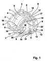
- Fig. 1 shows in a perspective view of an embodiment of a plug nut according to the invention, which made of a stamped and bent sheet metal section and for insertion into a recess of a in Fig. 1 not shown carrier part is provided.
- the nut according to Fig. 1 has one Cover plate 1 having a substantially rectangular shape, on the edge sides of each pairwise opposed long edge tongues 2 and 3 short edge tongues are formed.
- the edge tongues 2, 3 are outwardly over and serve to increase the contact surface of the cover plate 1 to the recess of the support member.
- a threaded sleeve 4 is formed as a female part having an internally threaded portion as a threaded portion.
- the female part is formed with punched and erected metal tabs, which serve as a threaded portion.
- each short edge tongue 3 two outer struts 5 of a first leg 6 and of a second leg 7 are attached to the cover plate 1, each having one end, which extend in a direction away from the cover plate 1.
- the outer struts 5 are attached with their facing away from the cover plate 1 ends each to a flat foot section 8, 9 of a leg 6, 7, wherein the foot sections 8, 9 are inclined and run towards each other.
- a foot section 8 is formed with inner inner tongues 10, 11 which laterally surround a small foot recess 12, while the other foot section 9 is provided with outer tongues 13, 14 lying on the outside of the inner tongues 10, 11, which laterally enclose a large foot recess 15 the inner tongues 10, 11 protrude into the large foot recess 15.
- the plug nut according to the invention is designed to be relatively compact at the end.
- two inner struts 17 are each attached with one end, which lie between the outer struts 5, are arranged at a distance from each other and extend from the respective foot section 8, 9 in the direction of the cover plate 1.
- the inner struts 17 run away from the outer struts 5 laterally outwardly away from each other, so that they have a greater distance from the inner side 16 facing away from the outer side of the outer struts 5 with increasing distance from the foot sections 8, 9.
- the respective foot section 8, 9 opposite ends of the inner struts 17 are attached to one end portion 18 of a leg 6, 7.
- the plate-like end portions 18 extend angled relative to the inner struts 17 in the direction of the cover plate 1 and the inner space 16 and enter between the laterally adjacent outer struts 5 a.
- the plug nut according to the invention is also compact in the region of the outside of the legs 6, 7 and can be handled as bulk material without excessive risk of entanglements
- a tongue 19 is formed in each case, the angled away in the Anform Scheme of the cover plate 1 and with their free ends in the direction of the interior 16 to each other, so that they substantially perpendicular to a high pull-out strength of the socket nut to the outer struts 5 are aligned.
- the ends of the tongues 19 facing away from the respective end section 18 are formed with a vaulted end face 20, which in the in Fig. 1 represented relaxed arrangement of the socket nut in extension of the outer wall of the threaded sleeve 4 are such that a screwed into the threaded sleeve 4 screw can pass substantially without disability between the tongues 17.
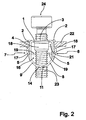
- Fig. 2 shows in a longitudinal section the embodiment according to Fig. 1 in an inserted into a recess 21 of a support member 22 arrangement, wherein in the threaded sleeve 4, a shaft 23 a for fixing a in Fig. 2 Anbauerss not shown on the support member 22 provided screw 24 is screwed in so far that it protrudes beyond the foot sections 8, 9 also beyond the cover plate 1 opposite end of the socket nut.
- the end faces 20 of the tongues 19 abut against the shaft 23 of the screw 24.
- compression of the side facing away from the cover plate 1 side on the support member 22 adjacent end portions 18 is blocked, and the pull-out strength of the inventive plug nut is particularly high.
- the proper arrangement of the plug nut according to the invention in the recess 21 is noticeable by a clearly audible snap sound as soon as the first pressed in between the outer struts 5 inner struts 17 passed through the recess 21 and are rebound to generate the snapping noise again.
Landscapes
- General Engineering & Computer Science (AREA)
- Engineering & Computer Science (AREA)
- Mechanical Engineering (AREA)
- Connection Of Plates (AREA)
- Insertion Pins And Rivets (AREA)
- Footwear And Its Accessory, Manufacturing Method And Apparatuses (AREA)
- Clamps And Clips (AREA)
- Surgical Instruments (AREA)
- Dowels (AREA)
- Mechanical Coupling Of Light Guides (AREA)
- Spark Plugs (AREA)
- Stereophonic System (AREA)
- Details Of Connecting Devices For Male And Female Coupling (AREA)
Description
- Die Erfindung betrifft eine Steckmutter gemäß dem Oberbegriff des Patentanspruches 1.
- Eine derartige Steckmutter ist aus
DE 35 24 651 A1 bekannt. Die vorbekannte, zum Einfügen in einer Ausnehmung eines Trägerteiles eingerichtete und aus einem gestanzten sowie gebogenen Blech hergestellte Steckmutter verfügt über eine Deckplatte, an der zwei einander gegenüberliegende und sich in einer Richtung weg von der Deckplatte erstreckende Schenkel angesetzt sind. Die Schenkel sind jeweils mit einem an der Deckplatte angesetzten Innenschenkel und mit einem an dem von der Deckplatte wegweisenden Ende des Innenschenkels angeformten, sich wieder in Richtung der Deckplatte erstreckenden Außenschenkel ausgebildet. Zwischen den Innenschenkeln ist ein Innenraum vorhanden. An den der Deckplatte zugewandten Enden der Außenschenkel sind in den Innenraum hineinragende Zungen angeformt. Die Deckplatte ist mit einem einen Gewindeabschnitt aufweisenden Mutterteil verbunden, wobei ein Schaft einer mit dem Mutterteil in Eingriff bringbaren Schraube in den Innenraum hineinragt, an dem die Stirnseiten der freien Enden der Zungen anliegen, so dass eine Bewegung der Außenschenkel in Richtung der Innenschenkel blockiert ist. Zwar weist diese Steckmutter eine hohe Auszugsfestigkeit auf, allerdings ist sie verhältnismäßig materialaufwändig ausgestaltet. - Aus
US-A-6,095,734 ist eine Steckmutter mit zwei Schenkeln bekannt, bei der jeder Schenkel zwei außenseitig angeordnete Außenstreben aufweist, zwischen denen eine nach innen gerichtete Zunge ausgebildet ist. - Der Erfindung liegt die Aufgabe zugrunde, eine Steckmutter der eingangs genannten Art anzugeben, die mit einem relativ geringen Materialaufwand eine verhältnismäßig hohe Auszugsfestigkeit erzielt.
- Diese Aufgabe wird bei einer Steckmutter der eingangs genannten Art erfindungsgemäß mit den kennzeichnenden Merkmalen des Patentanspruches 1 gelöst.
- Dadurch, dass bei der erfindungsgemäßen, aus einem gestanzten und gebogenen Blech hergestellte Steckmutter die Schenkel mit ineinander liegenden Außenstreben, Innenstreben und jeweils einer die Bewegung des jeweiligen Schenkels nach innen blockierende Zunge ausgebildet sind, ist der Materialaufwand bei verhältnismäßig hoher Auszugsfestigkeit sehr gering gehalten, da sich die Schenkel jeweils aus lediglich einem relativ kleinflächigen Streifen eines Blechabschnittes fertigen lassen.
- Weitere zweckmäßige Ausgestaltungen der Erfindung sind Gegenstand der Unteransprüche.
- Aus der nachfolgenden Beschreibung eines bevorzugten Ausführungsbeispiels der Erfindung unter Bezug auf die Figuren der Zeichnung ergeben sich weitere zweckmäßige Ausgestaltungen und Vorteile. Es zeigen:
- Fig. 1
- in einer perspektivischen Ansicht ein Ausführungsbeispiel einer erfindungsgemäßen Steckmutter und
- Fig. 2
- in einem Längsschnitt das Ausführungsbeispiel gemäß
Fig. 1 in einer in eine Ausnehmung eines Trägerteiles eingefügten Anordnung. -
Fig. 1 zeigt in einer perspektivischen Ansicht ein Ausführungsbeispiel einer erfindungsgemäßen Steckmutter, die aus einem gestanzten sowie gebogenen Blechabschnitt hergestellt und zum Einfügen in eine Ausnehmung eines inFig. 1 nicht dargestellten Trägerteiles vorgesehen ist. Die Steckmutter gemäßFig. 1 verfügt über eine Deckplatte 1 mit einer im wesentlichen rechteckartigen Gestalt, an deren Randseiten jeweils einander paarweise gegenüberliegende lange Randzungen 2 und kurze Randzungen 3 ausgebildet sind. Die Randzungen 2, 3 stehen nach außen über und dienen dem Vergrößern der Auflagefläche der Deckplatte 1 um die Ausnehmung des Trägerteiles. In der Mitte der Deckplatte 1 ist als Mutterteil eine Gewindehülse 4 angeformt, die ein Innengewindeabschnitt als Gewindeabschnitt aufweist. - Bei Abwandlungen der erfindungsgemäßen Steckmutter ist das Mutterteil mit ausgestanzten und aufgestellten Blechlappen ausgebildet, die als Gewindeabschnitt dienen.
- Beidseitig jeder kurzen Randzunge 3 sind an die Deckplatte 1 mit jeweils einem Ende zwei Außenstreben 5 eines ersten Schenkels 6 beziehungsweise eines zweiten Schenkels 7 angesetzt, die sich in einer Richtung von der Deckplatte 1 weg erstrecken. Die Außenstreben 5 sind mit ihren von der Deckplatte 1 wegweisenden Enden jeweils an einen flachen Fußabschnitt 8, 9 eines Schenkels 6, 7 angesetzt, wobei die Fußabschnitte 8, 9 schräg angestellt sind und aufeinander zu laufen. Ein Fußabschnitt 8 ist mit innen liegenden Innenzungen 10, 11 ausgebildet, die eine kleine Fußausnehmung 12 seitlich umschließen, während der andere Fußabschnitt 9 mit außenseitig der Innenzungen 10, 11 liegenden Außenzungen 13, 14 ausgestattet ist, die eine große Fußausnehmung 15 seitlich umschließen, wobei die Innenzungen 10, 11 in die große Fußausnehmung 15 hineinragen. Dadurch ist die erfindungsgemäße Steckmutter endseitig relativ kompakt ausgebildet.
- Zwischen den Schenkeln 6, 7 ist somit ein Innenraum 16 vorhanden, der zwischen den Schenkeln 6, 7 seitlich sowie in Richtung der Deckplatte 1 und der Fußabschnitte 8, 9 endseitig offen ist.
- An jedem Fußabschnitt 8, 9 sind mit jeweils einem Ende zwei Innenstreben 17 angesetzt, die zwischen den Außenstreben 5 liegen, in einem Abstand voneinander angeordnet sind und sich von dem jeweiligen Fußabschnitt 8, 9 in Richtung der Deckplatte 1 erstrecken. Die Innenstreben 17 laufen dabei gegenüber den Außenstreben 5 seitlich nach außen voneinander weg, so dass sie mit zunehmendem Abstand von den Fußabschnitten 8, 9 einen größeren Abstand von der dem Innenraum 16 abgewandten Außenseite der Außenstreben 5 aufweisen.
- Die dem jeweiligen Fußabschnitt 8, 9 gegenüberliegenden Enden der Innenstreben 17 sind an jeweils einen Endabschnitt 18 eines Schenkels 6, 7 angesetzt. Die plattenartigen Endabschnitte 18 erstrecken sich gegenüber den Innenstreben 17 abgewinkelt in Richtung der Deckplatte 1 sowie des Innenraumes 16 und treten zwischen die seitlich benachbarten Außenstreben 5 ein. Dadurch ist die erfindungsgemäße Steckmutter auch im Bereich der Außenseite der Schenkel 6, 7 kompakt ausgebildet und als Schüttgut ohne übergroße Gefahr von Verhakungen handhabbar
- An jeden Endabschnitt 18 ist jeweils eine Zunge 19 angeformt, die sich im Anformbereich von der Deckplatte 1 weg und mit ihren freien Enden abgewinkelt in Richtung des Innenraumes 16 aufeinander zu erstrecken, so dass sie im Hinblick auf eine hohe Auszugsfestigkeit der Steckmutter im Wesentlichen rechtwinklig zu den Außenstreben 5 ausgerichtet sind. Die von dem jeweiligen Endabschnitt 18 abgewandten Enden der Zungen 19 sind mit einer eingewölbten Stirnseite 20 ausgebildet, die in der in
Fig. 1 dargestellten relaxierten Anordnung der Steckmutter in Verlängerung der Außenwand der Gewindehülse 4 liegen, so dass eine in der die Gewindehülse 4 eingeschraubte Schraube im wesentlichen behinderungsfrei zwischen den Zungen 17 durchtreten kann. -
Fig. 2 zeigt in einem Längsschnitt das Ausführungsbeispiel gemäßFig. 1 in einer in eine Ausnehmung 21 eines Trägerteiles 22 eingefügten Anordnung, wobei in die Gewindehülse 4 ein Schaft 23 einer zum Befestigen eines inFig. 2 nicht dargestellten Anbauteiles an dem Trägerteil 22 vorgesehenen Schraube 24 so weit eingeschraubt ist, dass er über die Fußabschnitte 8, 9 hinaus über das der Deckplatte 1 abgewandten Ende der Steckmutter hinaussteht. AusFig. 2 ist ersichtlich, dass in dieser Anordnung die Stirnseiten 20 der Zungen 19 an dem Schaft 23 der Schraube 24 anliegen. Dadurch ist ein Einfedern der an der der Deckplatte 1 abgewandten Seite an dem Trägerteil 22 anliegenden Endabschnitte 18 blockiert, und die Auszugsfestigkeit der erfindungsgemäßen Steckmutter ist besonders hoch. - Weiterhin sei angemerkt, dass sich die ordnungsgemäße Anordnung der erfindungsgemäßen Steckmutter in der Ausnehmung 21 durch ein deutlich vernehmbares Schnappgeräusch bemerkbar macht, sobald die zunächst zwischen die Außenstreben 5 eingedrückten Innenstreben 17 durch die Ausnehmung 21 durchgetreten sowie unter Erzeugen des Schnappgeräusches wieder ausgefedert sind.
Claims (5)
- Steckmutter zum Einfügen in einer Ausnehmung eines Trägerteiles (22) mit einer Deckplatte (1), an der zwei einander gegenüberliegende und sich in einer Richtung weg von der Deckplatte (1) erstreckende Schenkel (6, 7) angesetzt sind und die mit einem einen Gewindeabschnitt aufweisenden Mutterteil (4) verbunden ist, wobei zwischen den Schenkeln (6, 7) ein Innenraum (16) zur Aufnahme des Schaftes (23) einer mit dem Mutterteil (4) in Eingriff bringbaren Schraube (24) ausgebildet ist, in den an den Schenkeln (6, 7) ausgebildete Zungen (19) hineinragen, dadurch gekennzeichnet, dass jeder Schenkel (6, 7) zwei außenseitig angeordnete Außenstreben (5) aufweist, die jeweils mit einem Ende an der Deckplatte (1) und mit ihrem anderen Ende an einem der Deckplatte (1) gegenüberliegenden endseitigen Fußabschnitt (8, 9) des jeweiligen Schenkels (6, 7) angesetzt sind, dass zwischen den Außenstreben (5) eines Schenkels (6, 7) zwei Innenstreben (17) angeordnet sind, die mit einem Ende an dem Fußabschnitt (8, 9) angesetzt sind und sich von den Fußabschnitten (8, 9) weg in Richtung der Deckplatte (1) erstrecken sowie mit einem Endabschnitt (18) in Verbindung stehen, wobei die Innenstreben (17) seitlich nach außen über die Außenstreben (5) überstehen, dass an jeden Endabschnitt (18) ein Ende einer der in den Innenraum (16) hineinragenden Zungen (19) angeformt ist, und dass sich die Zungen (19) im Anformbereich von dem jeweiligen Endabschnitt (18) von der Deckplatte (1) weg in Richtung des jeweiligen Fußabschnittes (8, 9) des Schenkels (6, 7) erstrecken.
- Steckmutter nach Anspruch 1, dadurch gekennzeichnet, dass die freien Enden der Zungen (19) rechtwinklig zu den Außenstreben (5) ausgerichtet sind.
- Steckmutter nach Anspruch 2, dadurch gekennzeichnet, dass an den Stirnseiten (20) der freien Enden der Zungen (19) jeweils eine nach innen gewölbte Ausnehmung ausgebildet ist.
- Steckmutter nach einem der Ansprüche 1 bis 3, dadurch gekennzeichnet, dass die Endabschnitte (18) schräg angestellt sind sowie in Richtung der Deckplatte (1) aufeinander zu laufen und zwischen seitlich benachbarten Außenstreben (5) angeordnet sind.
- Steckmutter nach einem der Ansprüche 1 bis 4, dadurch gekennzeichnet, dass an den Fußabschnitten (8, 9) aufeinander zu laufende und paarweise ineinanderliegende Innenzungen (10, 11) und Außenzungen (13, 14) ausgebildet sind.
Applications Claiming Priority (2)
| Application Number | Priority Date | Filing Date | Title |
|---|---|---|---|
| DE102006001741A DE102006001741A1 (de) | 2006-01-13 | 2006-01-13 | Steckmutter |
| PCT/EP2006/012443 WO2007087884A1 (de) | 2006-01-13 | 2006-12-22 | Steckmutter |
Publications (2)
| Publication Number | Publication Date |
|---|---|
| EP1977121A1 EP1977121A1 (de) | 2008-10-08 |
| EP1977121B1 true EP1977121B1 (de) | 2010-03-17 |
Family
ID=38001912
Family Applications (1)
| Application Number | Title | Priority Date | Filing Date |
|---|---|---|---|
| EP06841121A Active EP1977121B1 (de) | 2006-01-13 | 2006-12-22 | Steckmutter |
Country Status (6)
| Country | Link |
|---|---|
| US (1) | US7568870B2 (de) |
| EP (1) | EP1977121B1 (de) |
| AT (1) | ATE461372T1 (de) |
| DE (2) | DE102006001741A1 (de) |
| ES (1) | ES2341369T3 (de) |
| WO (1) | WO2007087884A1 (de) |
Cited By (1)
| Publication number | Priority date | Publication date | Assignee | Title |
|---|---|---|---|---|
| US10837481B2 (en) | 2018-02-22 | 2020-11-17 | A. Raymond Et Cie | Flush mount retainer assembly |
Families Citing this family (47)
| Publication number | Priority date | Publication date | Assignee | Title |
|---|---|---|---|---|
| JP2006308020A (ja) * | 2005-04-28 | 2006-11-09 | Piolax Inc | プッシュナット |
| KR101048732B1 (ko) * | 2006-04-26 | 2011-07-14 | 아 레이몽 에 씨에 에스쎄에스 | 고정 디바이스 |
| US8016530B2 (en) | 2008-01-10 | 2011-09-13 | Illinois Tool Works Inc. | Panel fastener |
| CA2768039C (en) * | 2009-07-24 | 2017-09-12 | Pem Management, Inc. | Quick acting panel fastener |
| ES2356761B1 (es) * | 2009-07-31 | 2012-02-29 | Illinois Tools Works Inc. | Clip de techo para la fijación de accesorios a los paneles de los veh�?culos. |
| EP2496848B1 (de) | 2009-11-04 | 2016-03-09 | Illinois Tool Works Inc. | Abnehmbare und wiederverwendbare blechmutter |
| US8388289B2 (en) | 2010-04-05 | 2013-03-05 | GM Global Technology Operations LLC | Self-supporting bracket nut |
| US8439620B2 (en) | 2010-06-23 | 2013-05-14 | Brian Mellyn | Speed nut |
| DE102011109829A1 (de) * | 2011-08-09 | 2013-02-14 | Valeo Schalter Und Sensoren Gmbh | Befestigungsanordnung eines Gehäuses einer Fahrzeugkomponente an einem Fahrzeugbauteil und Gehäuse für eine Fahrzeugkomponente |
| US8579570B2 (en) * | 2011-08-11 | 2013-11-12 | GM Global Technology Operations LLC | Fastener attaching a component to a panel |
| US8674219B2 (en) | 2011-11-01 | 2014-03-18 | Hubbell Incorporated | Mounting clip for electrical device |
| US8729388B2 (en) | 2011-11-01 | 2014-05-20 | Hubbell Incorporated | Mounting member for an electrical box assembly |
| US9500210B2 (en) * | 2012-03-02 | 2016-11-22 | Illinois Tool Works Inc. | Airbag anchoring clip assembly |
| US9322425B1 (en) * | 2013-03-05 | 2016-04-26 | William Feldman | Instrument clip |
| CN103591110A (zh) * | 2013-11-15 | 2014-02-19 | 上汽通用五菱汽车股份有限公司 | 一种螺母座 |
| FR3020098B1 (fr) * | 2014-04-22 | 2017-05-05 | A Raymond Et Cie | Dispositif de fixation par cramponnage |
| US9440596B2 (en) * | 2014-11-20 | 2016-09-13 | Ford Global Technologies, Llc | Retention clip for interior vehicle components |
| US9562554B2 (en) * | 2015-01-16 | 2017-02-07 | A. Raymond Et Cie | Retainer assembly |
| US9879803B2 (en) * | 2016-01-14 | 2018-01-30 | Maxdao Limited | Connectable cable organizer |
| US9835190B2 (en) | 2016-04-05 | 2017-12-05 | GM Global Technology Operations LLC | Stud clip insert for panel hole |
| WO2018144210A1 (en) | 2017-01-31 | 2018-08-09 | Illinois Tool Works Inc. | Ergonomic box nut retainer |
| DE202017101384U1 (de) * | 2017-03-10 | 2017-06-21 | Trox Gmbh | System zur lösbaren Befestigung eines Bauteils einer klima- und raumlufttechnischen Anlage |
| DE102017108335B4 (de) * | 2017-04-19 | 2019-01-03 | Rittal Gmbh & Co. Kg | Befestigungsanordnung und ein entsprechendes Schaltschrankgehäuse |
| WO2018217750A1 (en) * | 2017-05-22 | 2018-11-29 | Erico International Corporation | Push-on spring nut |
| CN109114081A (zh) * | 2017-06-23 | 2019-01-01 | 伊利诺斯工具制品有限公司 | 一种螺母紧固夹和螺母紧固夹组件 |
| CN107893799A (zh) * | 2017-12-19 | 2018-04-10 | 上海球明标准件有限公司 | 高便捷性上下体连接金属模块 |
| CN110388371A (zh) | 2018-04-18 | 2019-10-29 | 伊利诺斯工具制品有限公司 | 一种螺母紧固夹和螺母紧固夹组件 |
| USD874913S1 (en) | 2018-06-19 | 2020-02-11 | Illinois Tool Works Inc. | Nut retainer |
| EP3734088B1 (de) * | 2019-05-01 | 2023-03-22 | Erico International Corporation | Federmutter mit auslöser |
| KR102141902B1 (ko) * | 2019-05-15 | 2020-08-06 | 주식회사 니프코코리아 | 자동차용 푸시너트 |
| US10855000B1 (en) * | 2019-06-18 | 2020-12-01 | Te Connectivity Corporation | Grounding terminal |
| US11692581B2 (en) * | 2019-08-22 | 2023-07-04 | Illinois Tool Works Inc. | Box nut retainer |
| USD904866S1 (en) | 2019-08-23 | 2020-12-15 | Illinois Tool Works Inc. | Nut retainer |
| USD904865S1 (en) | 2019-08-23 | 2020-12-15 | Illinois Tool Works Inc. | Nut retainer |
| USD888546S1 (en) * | 2019-08-23 | 2020-06-30 | Illinois Tool Works Inc. | Nut retainer |
| US20210062855A1 (en) * | 2019-08-27 | 2021-03-04 | Illinois Tool Works Inc. | Ergonomic Box Nut Retainer |
| EP4211366B1 (de) * | 2020-09-14 | 2025-07-23 | Gates Corporation | Spannereinstellvorrichtung |
| USD1028701S1 (en) * | 2020-10-19 | 2024-05-28 | Illinois Tool Works Inc. | Nut |
| USD1029627S1 (en) * | 2020-12-23 | 2024-06-04 | Jonathan Winnie | Magnetic hook |
| US12049916B2 (en) | 2021-02-05 | 2024-07-30 | Erico International Corporation | Spring nut |
| US20230398952A1 (en) * | 2022-06-09 | 2023-12-14 | Illinois Tool Works Inc. | Emblem Retainer |
| US20240068501A1 (en) * | 2022-08-31 | 2024-02-29 | Illinois Tool Works Inc. | Corner Engage Clip with Integral Support Flange |
| KR102852266B1 (ko) * | 2023-03-21 | 2025-08-29 | 유진에스엠알시오토모티브테크노 주식회사 | 자동차용 푸쉬너트 |
| USD1124847S1 (en) * | 2025-02-19 | 2026-05-05 | Illinois Tool Works Inc. | Fastener |
| USD1124849S1 (en) * | 2025-03-12 | 2026-05-05 | Illinois Tool Works Inc. | Fastener |
| USD1124848S1 (en) * | 2025-03-12 | 2026-05-05 | Illinois Tool Works Inc. | Fastener |
| USD1124850S1 (en) * | 2025-03-12 | 2026-05-05 | Illinois Tool Works Inc. | Fastener |
Family Cites Families (9)
| Publication number | Priority date | Publication date | Assignee | Title |
|---|---|---|---|---|
| US2720135A (en) * | 1953-05-07 | 1955-10-11 | Gisondi Emanuel | Expanding screw anchor |
| GB1136128A (en) * | 1966-03-25 | 1968-12-11 | Carr Fastener Co Ltd | Sheet metal nut device |
| US4606688A (en) * | 1982-12-15 | 1986-08-19 | Eaton Corporation | Removable fastening assembly |
| US4610588A (en) * | 1984-07-24 | 1986-09-09 | Trw, Inc. | Fastener clip |
| US4925351A (en) * | 1989-03-21 | 1990-05-15 | Trw, Inc. | Push-in fastener clip |
| US6095734A (en) * | 1999-09-21 | 2000-08-01 | Transtechnology Corp. | Pushnut |
| US6908274B1 (en) * | 2000-11-20 | 2005-06-21 | Termax Corporation | Combination fastener |
| US7226260B2 (en) * | 2002-06-24 | 2007-06-05 | A. Raymond, Inc. | Sheet metal fastening clip |
| DE20319556U1 (de) | 2003-12-17 | 2004-03-11 | A. Raymond & Cie | Vorrichtung zum Verbinden eines Trägerteiles mit einem Anbauteil |
-
2006
- 2006-01-13 DE DE102006001741A patent/DE102006001741A1/de not_active Withdrawn
- 2006-12-22 DE DE502006006479T patent/DE502006006479D1/de active Active
- 2006-12-22 EP EP06841121A patent/EP1977121B1/de active Active
- 2006-12-22 ES ES06841121T patent/ES2341369T3/es active Active
- 2006-12-22 WO PCT/EP2006/012443 patent/WO2007087884A1/de not_active Ceased
- 2006-12-22 AT AT06841121T patent/ATE461372T1/de active
- 2006-12-22 US US12/092,330 patent/US7568870B2/en not_active Expired - Fee Related
Cited By (1)
| Publication number | Priority date | Publication date | Assignee | Title |
|---|---|---|---|---|
| US10837481B2 (en) | 2018-02-22 | 2020-11-17 | A. Raymond Et Cie | Flush mount retainer assembly |
Also Published As
| Publication number | Publication date |
|---|---|
| DE102006001741A1 (de) | 2007-08-02 |
| EP1977121A1 (de) | 2008-10-08 |
| WO2007087884A1 (de) | 2007-08-09 |
| ATE461372T1 (de) | 2010-04-15 |
| ES2341369T3 (es) | 2010-06-18 |
| US7568870B2 (en) | 2009-08-04 |
| US20080286066A1 (en) | 2008-11-20 |
| DE502006006479D1 (de) | 2010-04-29 |
Similar Documents
| Publication | Publication Date | Title |
|---|---|---|
| EP1977121A1 (de) | Steckmutter | |
| EP2182226B1 (de) | Befestigungsvorrichtung | |
| EP1697644B1 (de) | Vorrichtung zum verbinden eines trägerteiles mit einem anbauteil | |
| EP2536958B1 (de) | Befestigungsvorrichtung | |
| WO2007128375A1 (de) | Drehverschluss | |
| EP3058624B1 (de) | Steckverbinder mit verrastungssystem | |
| DE102014205467B4 (de) | Steckverbindungsanordnung | |
| DE9112178U1 (de) | Steckverbinder mit Kurzschlußbrücke | |
| EP2835878A1 (de) | Gehäusewandverschraubung für einen elektrischen Steckverbinder | |
| EP0935310A2 (de) | Kontaktelement mit einem Schraubanschluss | |
| WO2008025611A1 (de) | Einpressstift | |
| DE202017101396U1 (de) | Rundsteckverbinderbuchse für eine daran anordenbare Leiterplatte | |
| EP3026350B1 (de) | Dunstabzugshaube mit einer baueinheit | |
| EP2281122B1 (de) | Befestigungsklammer sowie anordnung mit einer befestigungssklammer und mit einem anbauteil | |
| EP0707745B1 (de) | Schraubklemme mit u-förmigem klemmkörper | |
| EP2324532B1 (de) | Elektrische vorrichtung mit schraubklemme | |
| EP2689496A1 (de) | Direktsteckelement, insbesondere für fahrzeugsteuergeräte | |
| EP2315952B1 (de) | Vorrichtung zum befestigen eines anbauteiles an einem trägerteil | |
| DE102005017688B4 (de) | Kabeldurchführung mit Schirmkontaktelement | |
| DE102006041803B4 (de) | Vorrichtung zur Befestigung eines Gerätes an einer Tragschiene | |
| EP1710863A1 (de) | Mit einer Drahtschutzfeder versehenes elektrisches Kontaktelement | |
| EP0170814B1 (de) | Spannfeder für die schraubenlose Befestigung von elektrischen Einbau-Geräten | |
| DE4231633C1 (en) | Plug connector fixing system using mounting plate - has slits in junction zone between fixing screw bores and adjacent edge | |
| DE202016104707U1 (de) | Elektrischer Kontaktsatz einer steckbaren Anschlussklemme | |
| DE202023101534U1 (de) | Stromschienenkontaktelement sowie Anordnung und Leiteranschlussklemme mit einer Stromschiene und einem Stromschienenkontaktelement |
Legal Events
| Date | Code | Title | Description |
|---|---|---|---|
| PUAI | Public reference made under article 153(3) epc to a published international application that has entered the european phase |
Free format text: ORIGINAL CODE: 0009012 |
|
| 17P | Request for examination filed |
Effective date: 20080813 |
|
| AK | Designated contracting states |
Kind code of ref document: A1 Designated state(s): AT BE BG CH CY CZ DE DK EE ES FI FR GB GR HU IE IS IT LI LT LU LV MC NL PL PT RO SE SI SK TR |
|
| 17Q | First examination report despatched |
Effective date: 20090205 |
|
| GRAP | Despatch of communication of intention to grant a patent |
Free format text: ORIGINAL CODE: EPIDOSNIGR1 |
|
| GRAS | Grant fee paid |
Free format text: ORIGINAL CODE: EPIDOSNIGR3 |
|
| GRAA | (expected) grant |
Free format text: ORIGINAL CODE: 0009210 |
|
| AK | Designated contracting states |
Kind code of ref document: B1 Designated state(s): AT BE BG CH CY CZ DE DK EE ES FI FR GB GR HU IE IS IT LI LT LU LV MC NL PL PT RO SE SI SK TR |
|
| REG | Reference to a national code |
Ref country code: GB Ref legal event code: FG4D Free format text: NOT ENGLISH |
|
| REG | Reference to a national code |
Ref country code: CH Ref legal event code: EP |
|
| REG | Reference to a national code |
Ref country code: IE Ref legal event code: FG4D |
|
| REF | Corresponds to: |
Ref document number: 502006006479 Country of ref document: DE Date of ref document: 20100429 Kind code of ref document: P |
|
| REG | Reference to a national code |
Ref country code: RO Ref legal event code: EPE |
|
| REG | Reference to a national code |
Ref country code: ES Ref legal event code: FG2A Ref document number: 2341369 Country of ref document: ES Kind code of ref document: T3 |
|
| REG | Reference to a national code |
Ref country code: NL Ref legal event code: VDEP Effective date: 20100317 |
|
| PG25 | Lapsed in a contracting state [announced via postgrant information from national office to epo] |
Ref country code: LT Free format text: LAPSE BECAUSE OF FAILURE TO SUBMIT A TRANSLATION OF THE DESCRIPTION OR TO PAY THE FEE WITHIN THE PRESCRIBED TIME-LIMIT Effective date: 20100317 |
|
| LTIE | Lt: invalidation of european patent or patent extension |
Effective date: 20100317 |
|
| PG25 | Lapsed in a contracting state [announced via postgrant information from national office to epo] |
Ref country code: LV Free format text: LAPSE BECAUSE OF FAILURE TO SUBMIT A TRANSLATION OF THE DESCRIPTION OR TO PAY THE FEE WITHIN THE PRESCRIBED TIME-LIMIT Effective date: 20100317 Ref country code: PL Free format text: LAPSE BECAUSE OF FAILURE TO SUBMIT A TRANSLATION OF THE DESCRIPTION OR TO PAY THE FEE WITHIN THE PRESCRIBED TIME-LIMIT Effective date: 20100317 Ref country code: FI Free format text: LAPSE BECAUSE OF FAILURE TO SUBMIT A TRANSLATION OF THE DESCRIPTION OR TO PAY THE FEE WITHIN THE PRESCRIBED TIME-LIMIT Effective date: 20100317 Ref country code: SI Free format text: LAPSE BECAUSE OF FAILURE TO SUBMIT A TRANSLATION OF THE DESCRIPTION OR TO PAY THE FEE WITHIN THE PRESCRIBED TIME-LIMIT Effective date: 20100317 |
|
| REG | Reference to a national code |
Ref country code: IE Ref legal event code: FD4D |
|
| PG25 | Lapsed in a contracting state [announced via postgrant information from national office to epo] |
Ref country code: EE Free format text: LAPSE BECAUSE OF FAILURE TO SUBMIT A TRANSLATION OF THE DESCRIPTION OR TO PAY THE FEE WITHIN THE PRESCRIBED TIME-LIMIT Effective date: 20100317 Ref country code: NL Free format text: LAPSE BECAUSE OF FAILURE TO SUBMIT A TRANSLATION OF THE DESCRIPTION OR TO PAY THE FEE WITHIN THE PRESCRIBED TIME-LIMIT Effective date: 20100317 Ref country code: CY Free format text: LAPSE BECAUSE OF FAILURE TO SUBMIT A TRANSLATION OF THE DESCRIPTION OR TO PAY THE FEE WITHIN THE PRESCRIBED TIME-LIMIT Effective date: 20100317 Ref country code: SE Free format text: LAPSE BECAUSE OF FAILURE TO SUBMIT A TRANSLATION OF THE DESCRIPTION OR TO PAY THE FEE WITHIN THE PRESCRIBED TIME-LIMIT Effective date: 20100317 Ref country code: GR Free format text: LAPSE BECAUSE OF FAILURE TO SUBMIT A TRANSLATION OF THE DESCRIPTION OR TO PAY THE FEE WITHIN THE PRESCRIBED TIME-LIMIT Effective date: 20100618 |
|
| PG25 | Lapsed in a contracting state [announced via postgrant information from national office to epo] |
Ref country code: IS Free format text: LAPSE BECAUSE OF FAILURE TO SUBMIT A TRANSLATION OF THE DESCRIPTION OR TO PAY THE FEE WITHIN THE PRESCRIBED TIME-LIMIT Effective date: 20100717 Ref country code: SK Free format text: LAPSE BECAUSE OF FAILURE TO SUBMIT A TRANSLATION OF THE DESCRIPTION OR TO PAY THE FEE WITHIN THE PRESCRIBED TIME-LIMIT Effective date: 20100317 Ref country code: BG Free format text: LAPSE BECAUSE OF FAILURE TO SUBMIT A TRANSLATION OF THE DESCRIPTION OR TO PAY THE FEE WITHIN THE PRESCRIBED TIME-LIMIT Effective date: 20100617 |
|
| PLBE | No opposition filed within time limit |
Free format text: ORIGINAL CODE: 0009261 |
|
| STAA | Information on the status of an ep patent application or granted ep patent |
Free format text: STATUS: NO OPPOSITION FILED WITHIN TIME LIMIT |
|
| PG25 | Lapsed in a contracting state [announced via postgrant information from national office to epo] |
Ref country code: PT Free format text: LAPSE BECAUSE OF FAILURE TO SUBMIT A TRANSLATION OF THE DESCRIPTION OR TO PAY THE FEE WITHIN THE PRESCRIBED TIME-LIMIT Effective date: 20100719 Ref country code: DK Free format text: LAPSE BECAUSE OF FAILURE TO SUBMIT A TRANSLATION OF THE DESCRIPTION OR TO PAY THE FEE WITHIN THE PRESCRIBED TIME-LIMIT Effective date: 20100317 Ref country code: IE Free format text: LAPSE BECAUSE OF FAILURE TO SUBMIT A TRANSLATION OF THE DESCRIPTION OR TO PAY THE FEE WITHIN THE PRESCRIBED TIME-LIMIT Effective date: 20100317 |
|
| 26N | No opposition filed |
Effective date: 20101220 |
|
| PGFP | Annual fee paid to national office [announced via postgrant information from national office to epo] |
Ref country code: IT Payment date: 20101216 Year of fee payment: 5 Ref country code: GB Payment date: 20101119 Year of fee payment: 5 |
|
| BERE | Be: lapsed |
Owner name: A. RAYMOND ET CIE Effective date: 20101231 |
|
| PG25 | Lapsed in a contracting state [announced via postgrant information from national office to epo] |
Ref country code: MC Free format text: LAPSE BECAUSE OF NON-PAYMENT OF DUE FEES Effective date: 20101231 |
|
| REG | Reference to a national code |
Ref country code: CH Ref legal event code: PL |
|
| PG25 | Lapsed in a contracting state [announced via postgrant information from national office to epo] |
Ref country code: BE Free format text: LAPSE BECAUSE OF NON-PAYMENT OF DUE FEES Effective date: 20101231 |
|
| PG25 | Lapsed in a contracting state [announced via postgrant information from national office to epo] |
Ref country code: CH Free format text: LAPSE BECAUSE OF NON-PAYMENT OF DUE FEES Effective date: 20101231 Ref country code: LI Free format text: LAPSE BECAUSE OF NON-PAYMENT OF DUE FEES Effective date: 20101231 |
|
| PG25 | Lapsed in a contracting state [announced via postgrant information from national office to epo] |
Ref country code: HU Free format text: LAPSE BECAUSE OF FAILURE TO SUBMIT A TRANSLATION OF THE DESCRIPTION OR TO PAY THE FEE WITHIN THE PRESCRIBED TIME-LIMIT Effective date: 20100918 Ref country code: LU Free format text: LAPSE BECAUSE OF NON-PAYMENT OF DUE FEES Effective date: 20101222 |
|
| PG25 | Lapsed in a contracting state [announced via postgrant information from national office to epo] |
Ref country code: TR Free format text: LAPSE BECAUSE OF FAILURE TO SUBMIT A TRANSLATION OF THE DESCRIPTION OR TO PAY THE FEE WITHIN THE PRESCRIBED TIME-LIMIT Effective date: 20100317 |
|
| REG | Reference to a national code |
Ref country code: AT Ref legal event code: MM01 Ref document number: 461372 Country of ref document: AT Kind code of ref document: T Effective date: 20111222 |
|
| PG25 | Lapsed in a contracting state [announced via postgrant information from national office to epo] |
Ref country code: AT Free format text: LAPSE BECAUSE OF NON-PAYMENT OF DUE FEES Effective date: 20111222 |
|
| GBPC | Gb: european patent ceased through non-payment of renewal fee |
Effective date: 20121222 |
|
| PG25 | Lapsed in a contracting state [announced via postgrant information from national office to epo] |
Ref country code: GB Free format text: LAPSE BECAUSE OF NON-PAYMENT OF DUE FEES Effective date: 20121222 |
|
| PG25 | Lapsed in a contracting state [announced via postgrant information from national office to epo] |
Ref country code: IT Free format text: LAPSE BECAUSE OF NON-PAYMENT OF DUE FEES Effective date: 20121222 |
|
| REG | Reference to a national code |
Ref country code: DE Ref legal event code: R082 Ref document number: 502006006479 Country of ref document: DE |
|
| REG | Reference to a national code |
Ref country code: FR Ref legal event code: PLFP Year of fee payment: 10 |
|
| REG | Reference to a national code |
Ref country code: FR Ref legal event code: PLFP Year of fee payment: 11 |
|
| REG | Reference to a national code |
Ref country code: FR Ref legal event code: PLFP Year of fee payment: 12 |
|
| P01 | Opt-out of the competence of the unified patent court (upc) registered |
Effective date: 20230524 |
|
| PGFP | Annual fee paid to national office [announced via postgrant information from national office to epo] |
Ref country code: DE Payment date: 20251211 Year of fee payment: 20 |
|
| PGFP | Annual fee paid to national office [announced via postgrant information from national office to epo] |
Ref country code: FR Payment date: 20251222 Year of fee payment: 20 |
|
| PGFP | Annual fee paid to national office [announced via postgrant information from national office to epo] |
Ref country code: CZ Payment date: 20251218 Year of fee payment: 20 |
|
| PGFP | Annual fee paid to national office [announced via postgrant information from national office to epo] |
Ref country code: RO Payment date: 20251216 Year of fee payment: 20 |
|
| PGFP | Annual fee paid to national office [announced via postgrant information from national office to epo] |
Ref country code: ES Payment date: 20260130 Year of fee payment: 20 |