EP1976005A2 - Thermally conductive sheet and method of manufacturing the same - Google Patents
Thermally conductive sheet and method of manufacturing the same Download PDFInfo
- Publication number
- EP1976005A2 EP1976005A2 EP08153468A EP08153468A EP1976005A2 EP 1976005 A2 EP1976005 A2 EP 1976005A2 EP 08153468 A EP08153468 A EP 08153468A EP 08153468 A EP08153468 A EP 08153468A EP 1976005 A2 EP1976005 A2 EP 1976005A2
- Authority
- EP
- European Patent Office
- Prior art keywords
- layer
- thermally conductive
- polymer layer
- sheet
- adhesive layer
- Prior art date
- Legal status (The legal status is an assumption and is not a legal conclusion. Google has not performed a legal analysis and makes no representation as to the accuracy of the status listed.)
- Granted
Links
Images


Classifications
-
- H—ELECTRICITY
- H01—ELECTRIC ELEMENTS
- H01L—SEMICONDUCTOR DEVICES NOT COVERED BY CLASS H10
- H01L23/00—Details of semiconductor or other solid state devices
- H01L23/34—Arrangements for cooling, heating, ventilating or temperature compensation ; Temperature sensing arrangements
- H01L23/36—Selection of materials, or shaping, to facilitate cooling or heating, e.g. heatsinks
- H01L23/373—Cooling facilitated by selection of materials for the device or materials for thermal expansion adaptation, e.g. carbon
- H01L23/3735—Laminates or multilayers, e.g. direct bond copper ceramic substrates
-
- H—ELECTRICITY
- H01—ELECTRIC ELEMENTS
- H01L—SEMICONDUCTOR DEVICES NOT COVERED BY CLASS H10
- H01L23/00—Details of semiconductor or other solid state devices
- H01L23/34—Arrangements for cooling, heating, ventilating or temperature compensation ; Temperature sensing arrangements
- H01L23/36—Selection of materials, or shaping, to facilitate cooling or heating, e.g. heatsinks
- H01L23/373—Cooling facilitated by selection of materials for the device or materials for thermal expansion adaptation, e.g. carbon
- H01L23/3733—Cooling facilitated by selection of materials for the device or materials for thermal expansion adaptation, e.g. carbon having a heterogeneous or anisotropic structure, e.g. powder or fibres in a matrix, wire mesh, porous structures
-
- H—ELECTRICITY
- H01—ELECTRIC ELEMENTS
- H01L—SEMICONDUCTOR DEVICES NOT COVERED BY CLASS H10
- H01L23/00—Details of semiconductor or other solid state devices
- H01L23/34—Arrangements for cooling, heating, ventilating or temperature compensation ; Temperature sensing arrangements
- H01L23/36—Selection of materials, or shaping, to facilitate cooling or heating, e.g. heatsinks
- H01L23/373—Cooling facilitated by selection of materials for the device or materials for thermal expansion adaptation, e.g. carbon
- H01L23/3737—Organic materials with or without a thermoconductive filler
-
- H—ELECTRICITY
- H05—ELECTRIC TECHNIQUES NOT OTHERWISE PROVIDED FOR
- H05K—PRINTED CIRCUITS; CASINGS OR CONSTRUCTIONAL DETAILS OF ELECTRIC APPARATUS; MANUFACTURE OF ASSEMBLAGES OF ELECTRICAL COMPONENTS
- H05K7/00—Constructional details common to different types of electric apparatus
- H05K7/20—Modifications to facilitate cooling, ventilating, or heating
-
- H—ELECTRICITY
- H01—ELECTRIC ELEMENTS
- H01L—SEMICONDUCTOR DEVICES NOT COVERED BY CLASS H10
- H01L2224/00—Indexing scheme for arrangements for connecting or disconnecting semiconductor or solid-state bodies and methods related thereto as covered by H01L24/00
- H01L2224/01—Means for bonding being attached to, or being formed on, the surface to be connected, e.g. chip-to-package, die-attach, "first-level" interconnects; Manufacturing methods related thereto
- H01L2224/26—Layer connectors, e.g. plate connectors, solder or adhesive layers; Manufacturing methods related thereto
- H01L2224/28—Structure, shape, material or disposition of the layer connectors prior to the connecting process
- H01L2224/29—Structure, shape, material or disposition of the layer connectors prior to the connecting process of an individual layer connector
- H01L2224/29001—Core members of the layer connector
- H01L2224/29099—Material
- H01L2224/29198—Material with a principal constituent of the material being a combination of two or more materials in the form of a matrix with a filler, i.e. being a hybrid material, e.g. segmented structures, foams
- H01L2224/29298—Fillers
- H01L2224/29499—Shape or distribution of the fillers
-
- H—ELECTRICITY
- H01—ELECTRIC ELEMENTS
- H01L—SEMICONDUCTOR DEVICES NOT COVERED BY CLASS H10
- H01L2924/00—Indexing scheme for arrangements or methods for connecting or disconnecting semiconductor or solid-state bodies as covered by H01L24/00
- H01L2924/0001—Technical content checked by a classifier
- H01L2924/0002—Not covered by any one of groups H01L24/00, H01L24/00 and H01L2224/00
-
- H—ELECTRICITY
- H01—ELECTRIC ELEMENTS
- H01L—SEMICONDUCTOR DEVICES NOT COVERED BY CLASS H10
- H01L2924/00—Indexing scheme for arrangements or methods for connecting or disconnecting semiconductor or solid-state bodies as covered by H01L24/00
- H01L2924/10—Details of semiconductor or other solid state devices to be connected
- H01L2924/11—Device type
- H01L2924/12—Passive devices, e.g. 2 terminal devices
- H01L2924/1204—Optical Diode
- H01L2924/12044—OLED
-
- Y—GENERAL TAGGING OF NEW TECHNOLOGICAL DEVELOPMENTS; GENERAL TAGGING OF CROSS-SECTIONAL TECHNOLOGIES SPANNING OVER SEVERAL SECTIONS OF THE IPC; TECHNICAL SUBJECTS COVERED BY FORMER USPC CROSS-REFERENCE ART COLLECTIONS [XRACs] AND DIGESTS
- Y10—TECHNICAL SUBJECTS COVERED BY FORMER USPC
- Y10T—TECHNICAL SUBJECTS COVERED BY FORMER US CLASSIFICATION
- Y10T156/00—Adhesive bonding and miscellaneous chemical manufacture
- Y10T156/10—Methods of surface bonding and/or assembly therefor
-
- Y—GENERAL TAGGING OF NEW TECHNOLOGICAL DEVELOPMENTS; GENERAL TAGGING OF CROSS-SECTIONAL TECHNOLOGIES SPANNING OVER SEVERAL SECTIONS OF THE IPC; TECHNICAL SUBJECTS COVERED BY FORMER USPC CROSS-REFERENCE ART COLLECTIONS [XRACs] AND DIGESTS
- Y10—TECHNICAL SUBJECTS COVERED BY FORMER USPC
- Y10T—TECHNICAL SUBJECTS COVERED BY FORMER US CLASSIFICATION
- Y10T428/00—Stock material or miscellaneous articles
- Y10T428/24—Structurally defined web or sheet [e.g., overall dimension, etc.]
- Y10T428/24802—Discontinuous or differential coating, impregnation or bond [e.g., artwork, printing, retouched photograph, etc.]
- Y10T428/24826—Spot bonds connect components
-
- Y—GENERAL TAGGING OF NEW TECHNOLOGICAL DEVELOPMENTS; GENERAL TAGGING OF CROSS-SECTIONAL TECHNOLOGIES SPANNING OVER SEVERAL SECTIONS OF THE IPC; TECHNICAL SUBJECTS COVERED BY FORMER USPC CROSS-REFERENCE ART COLLECTIONS [XRACs] AND DIGESTS
- Y10—TECHNICAL SUBJECTS COVERED BY FORMER USPC
- Y10T—TECHNICAL SUBJECTS COVERED BY FORMER US CLASSIFICATION
- Y10T428/00—Stock material or miscellaneous articles
- Y10T428/24—Structurally defined web or sheet [e.g., overall dimension, etc.]
- Y10T428/24802—Discontinuous or differential coating, impregnation or bond [e.g., artwork, printing, retouched photograph, etc.]
- Y10T428/24851—Intermediate layer is discontinuous or differential
-
- Y—GENERAL TAGGING OF NEW TECHNOLOGICAL DEVELOPMENTS; GENERAL TAGGING OF CROSS-SECTIONAL TECHNOLOGIES SPANNING OVER SEVERAL SECTIONS OF THE IPC; TECHNICAL SUBJECTS COVERED BY FORMER USPC CROSS-REFERENCE ART COLLECTIONS [XRACs] AND DIGESTS
- Y10—TECHNICAL SUBJECTS COVERED BY FORMER USPC
- Y10T—TECHNICAL SUBJECTS COVERED BY FORMER US CLASSIFICATION
- Y10T428/00—Stock material or miscellaneous articles
- Y10T428/24—Structurally defined web or sheet [e.g., overall dimension, etc.]
- Y10T428/24802—Discontinuous or differential coating, impregnation or bond [e.g., artwork, printing, retouched photograph, etc.]
- Y10T428/24893—Discontinuous or differential coating, impregnation or bond [e.g., artwork, printing, retouched photograph, etc.] including particulate material
-
- Y—GENERAL TAGGING OF NEW TECHNOLOGICAL DEVELOPMENTS; GENERAL TAGGING OF CROSS-SECTIONAL TECHNOLOGIES SPANNING OVER SEVERAL SECTIONS OF THE IPC; TECHNICAL SUBJECTS COVERED BY FORMER USPC CROSS-REFERENCE ART COLLECTIONS [XRACs] AND DIGESTS
- Y10—TECHNICAL SUBJECTS COVERED BY FORMER USPC
- Y10T—TECHNICAL SUBJECTS COVERED BY FORMER US CLASSIFICATION
- Y10T428/00—Stock material or miscellaneous articles
- Y10T428/24—Structurally defined web or sheet [e.g., overall dimension, etc.]
- Y10T428/24942—Structurally defined web or sheet [e.g., overall dimension, etc.] including components having same physical characteristic in differing degree
Definitions
- the present invention relates to a thermally conductive sheet used to release heat generated by semiconductor devices and various types of electronic parts which are heat emitting bodies and a method of manufacturing the same.
- Thermally conductive sheets, thermally conductive grease, thermally conductive adhesives, phase change members having thermal conductivity and the like are inserted between heat emitting bodies mounted on circuit boards for conventional electronics and heat discharging bodies in order to release heat generated by the heat emitting bodies.
- heat emitting bodies include semiconductor devices and electronic parts.
- heat discharging bodies include heat sinks and cooling fans.
- the power consumption and amount of heat emission of electronic parts have increased as the functions and performance of electronics have increased.
- the space within the housing of electronics for arranging members, such as circuit boards has been becoming smaller as the scale and the thickness of electronics have been reduced.
- thermal diffusion sheets formed of graphite or a metal material are used in order to effectively diffuse heat generated by a heat emitting body within the limited space inside the housing.
- a thermal diffusion sheet having excellent properties in terms of thermal diffusion has been required.
- the thermal diffusion sheet makes direct contact with a heat emitting body, the thermal diffusion sheet does not stick to the shape of the contour of the heat emitting body, due to the high rigidity of the graphite or metal material that forms the thermal diffusion sheet. Therefore, the thermal diffusion sheet cannot make sufficiently close contact with the heat emitting body, and thus, excellent properties in terms of thermal diffusion cannot be gained.
- Japanese Laid-Open Patent Publication No. 2003-168882 Japanese Laid-Open Patent Publication No. 2005-57088 and Japanese Laid-Open Patent Publication No. 2004-243650 disclose thermally conductive sheets where a flexible thermally conductive polymer layer is layered on at least one side of a thermal diffusion layer formed of, for example, graphite, in order to gain excellent properties in terms of thermal diffusion.
- Various functions are required, in addition to the above described properties in terms of thermal diffusion, for thermally conductive sheets, depending on where they are used.
- the thermally conductive sheets described in the above described gazettes do not meet these requirements.
- An object of the present invention is to provide a thermally conductive sheet which is more appropriate for use in applications where heat release from heat emitting bodies is required.
- the present invention also relates to a method of manufacturing the thermally conductive sheet.
- a thermally conductive sheet includes a thermally conductive polymer layer formed of a thermally conductive polymer composition, an adhesive layer provided on an outer surface of the thermally conductive polymer layer, and a functional layer provided on the adhesive layer.
- the thermally conductive polymer composition contains a polymer matrix and a thermally conductive filler.
- the coefficient of static friction of the thermally conductive polymer layer is 1.0 or lower.
- the adhesive layer and the thermally conductive polymer layer each have an outer shape and the outer shape of the adhesive layer is smaller than the outer shape of the thermally conductive polymer layer.
- a method for manufacturing a thermally conductive sheet includes: forming a thermally conductive polymer layer of a thermally conductive polymer composition containing a polymer matrix and a thermally conductive filler in which the coefficient of static friction of the thermally conductive polymer layer is 1.0 or lower and the thermally conductive polymer layer includes an outer shape; providing an adhesive layer on an outer surface of the thermally conductive polymer layer in which the adhesive layer has an outer shape smaller than the outer shape of the thermally conductive polymer layer; and providing a functional layer on the adhesive layer.
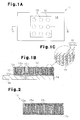
- the thermally conductive sheet 11 comprises a thermally conductive polymer layer 12 formed of a thermally conductive polymer composition, an adhesive layer 13 formed on the outer surface 12a of the thermally conductive polymer layer 12, and a thermal diffusion layer 14, which is a functional layer formed on the adhesive layer 13.
- the layers are in the order of: thermal diffusion layer 14, adhesive layer 13, thermally conductive polymer layer 12, from the bottom.
- the thermally conductive sheet 11 is simply referred to as sheet 11, the thermally conductive polymer composition is simply referred to as composition, and the thermally conductive polymer layer 12 is simply referred to as polymer layer 12.
- the sheet 11 is inserted between a heat emitting body and a heat discharging body, for example, for use, so that heat is discharged from the hot heat emitting body and the heat emitting body is cooled.
- the sheet 11 is provided with a cooling function and is easy to handle.
- the cooling function is an index for ease of cooling a hot heat emitting body, and based on the thermal conductivity of the polymer layer 12 and the properties of the thermal diffusion layer 14 in terms of thermal diffusion. That is to say, the cooling function is based on the thermal conductivity of the polymer layer 12, the value of the thermal resistance of the polymer layer 12, the adhesion between the heat emitting body or heat discharging body and the polymer layer 12, as well as that between the thermal diffusion layer 14 and the polymer layer 12, and the properties of the thermal diffusion layer 14 in terms of thermal diffusion.
- the ease of handling is an index for the ease of handling when the sheet 11 is carried and the like, and mainly based on the adhesiveness of the polymer layer 12.
- the composition contains a polymer matrix and a thermally conductive filler.
- the polymer matrix holds the thermally conductive filler within the polymer layer 12.
- the polymer matrix is selected in accordance with the performance required for the polymer layer 12, for example mechanical strength, hardness, durability, resistance to heat, and electrical properties. Specific examples of the polymer matrix include silicone resin.
- the thermally conductive filler increases the thermal conductivity of the polymer layer 12 so that the cooling function of the sheet 11 increases.
- the form of the thermally conductive filler include fiber, particle, and plate forms.
- at least part of the thermally conductive filler is in fiber form.
- a thermally conductive filler in fiber form that is to say, a sheet 11 containing a filler in fiber form
- the filler in fiber form include carbon fibers and poly(p-phenylenebenzobisoxazole) precursor carbon fibers (PBO carbon fibers).
- materials for thermally conductive fillers having a form other than fiber form, that is to say, fillers in non-fiber form include aluminum oxide and aluminum hydroxide.
- the thermally conductive filler content in the composition is preferable for the thermally conductive filler content in the composition to be 90 mass % or less.
- the thermally conductive filler content exceeds 90 mass %, the polymer layer 12 becomes fragile, because the flexibility of the polymer layer 12 is low, and at the same time, there is a risk that the polymer layer 12 may not stick to the shape of the contour of the heat emitting body and the heat discharging body as much.
- the composition may contain a plasticizer for adjusting the hardness of, for example, the polymer layer 12, and a stabilizer for enhancing the durability, in addition to the above described components.
- the polymer layer 12 is in quadrilateral form and accelerates thermal conduction from the heat emitting body to the heat discharging body so that the hot heat emitting body is cooled.
- the polymer layer 12 is provided with a polymer matrix 15 and a thermally conductive filler 16.
- the thermally conductive filler 16 according to the present embodiment has a thermally conductive filler 16 in fiber form, that is to say, filler in fiber form 16a and a thermally conductive filler 16 in particle form, that is to say, a filler in particle form 16b.
- the filler in fiber form 16a is oriented in one direction. In the polymer layer 12 shown in Figs.
- the filler in fiber form 16a is oriented in the direction of the thickness of the polymer layer 12. Therefore, the value of the thermal conductivity of the polymer layer 12 in the direction of the thickness is equal to the value gained by multiplying the value of the thermal conductivity in the direction of the width by two to several hundred.
- the end portions of the filler in fiber form 16a extend in the direction of the width of the polymer layer 12 and are exposed on pairs of facing outer surfaces 12a.
- the adhesiveness of the polymer layer 12 is very small, and therefore, the adhesiveness of the polymer layer 12 can be indicated using the coefficient of static friction of the polymer layer 12. That is to say, in the case where the coefficient of static friction of the polymer layer 12 is low, the adhesiveness of the polymer layer 12 is low, while in the case where the coefficient of static friction of the polymer layer 12 is high, the adhesiveness of the polymer layer 12 is high.
- the coefficient of static friction of the polymer layer 12 is 1.0 or lower, preferably 0.3 or lower. In the case where the coefficient of static friction of the polymer layer 12 exceeds 1.0, it becomes difficult to attach the sheet 11 to the heat emitting body, for example, due to excessively high adhesiveness of the polymer layer 12.
- the lower limit for the coefficient of static friction of the polymer layer 12 is not particularly limited, and the smaller the coefficient of static friction of the polymer layer 12 is, the easier it is to attach the sheet 11 to the heat emitting body, for example.
- the coefficient of static friction of the polymer layer 12 is 1.0 or lower, the polymer layer 12 is not sticky when the outer surfaces 12a of the polymer 12 are touched with the fingers, and thus, the polymer layer 12 does not adhere to the thermal diffusion layer 14 through its own adhesiveness.
- the thickness of the polymer layer 12 is preferably 0.03 mm to 0.5 mm. In the case where the thickness of the polymer layer 12 is less than 0.03 mm, the manufacture of the polymer layer 12 becomes difficult. In the case where the thickness of the polymer layer 12 exceeds 0.5 mm, it takes time for the heat to conduct from the heat emitting body to the heat discharging body, and there is a risk that the cooling function of the sheet 11 may deteriorate. Polymer layers 12 having a thickness of 0.5 mm or less easily become flexible, due to the material.
- the hardness of the polymer layer 12 as measured in accordance with the type E of JIS K 6253, which is a Japanese Industrial Standard (ISO 7619-1, which is an international standard), is 5 to 80, for example.
- the hardness of the polymer layer 12 is less than 5
- the polymer layer 12 is too flexible, and therefore, the ease of handling of the sheet 11 deteriorates.
- the adhesion between the polymer layer 12 and the heat emitting body or heat discharging body decreases, and there is a risk that the cooling function of the sheet 11 may deteriorate.
- the outer shape of the adhesive layer 13 is smaller than the outer shape of the polymer layer 12, and in multi-dot form throughout the entirety of the outer surfaces 12a of the polymer layer 12.
- the adhesive layer 13 holds the polymer layer 12 and the thermal diffusion layer 14 together through the adhesive layer 13.
- the material for the adhesive layer 13 include acryl based, silicone based, urethane based, vinyl based and synthetic rubber based gluing agents and adhesives.
- the adhesive layer 13 is formed through application of a material for forming the adhesive layer 13 to the polymer layer 12.
- the adhesive layer 13 may be formed of an adhesive tape where the above described adhesive is applied to a polymer film, which has the same effects.
- the polymer layer 12 easily adheres to the thermal diffusion layer 14, and therefore, it is preferable for the material for the adhesive layer 13 to have flexibility.
- the ratio of the area occupied by the adhesive layer 13 to the entirety of the outer surfaces 12a on the outer surfaces 12a to which the adhesive layer 13 of the polymer layer 12 is attached is preferably 30% or less.
- the thermal conductivity of the adhesive layer 13 and the properties of the adhesive layer 13 in terms of thermal diffusion are poor in comparison with the thermal conductivity of the polymer layer 12 and the properties of the thermal diffusion layer 14 in terms of thermal diffusion. Therefore, when the ratio of the area occupied by the adhesive layer 13 exceeds 30%, there is a risk that the cooling function of the sheet 11 may deteriorate excessively.
- the thickness of the adhesive layer 13 is preferably 50 ⁇ m or less. In the case where the thickness of the adhesive layer 13 exceeds 50 ⁇ m, the difference between the outer surface of the polymer layer 12 and the surface of the adhesive layer 13 becomes great due to the thickness of the adhesive layer 13. Therefore, there is a risk that the adhesion between the polymer layer 12 and the thermal diffusion layer 14 may decrease, and the value of the thermal contact resistance of the sheet 11 may become high when the sheet 11 is attached to a heat emitting body, for example. As described above, the thermal conductivity of the adhesive layer 13 is poor in comparison with the thermal conductivity of the polymer layer 12.
- the lower limit for the thickness of the adhesive layer 13 is not particularly limited, and the thinner the adhesive layer 13, the higher the adhesion between the polymer layer 12 and the thermal diffusion layer 14 becomes, and the lower the ratio of the adhesive layer 13 in the direction of the thermal conductance in the sheet 11 becomes. Thus, the lower the value of the thermal contact resistance of the sheet 11 becomes.
- the thermal diffusion layer 14 is in quadrilateral form and allows heat to diffuse from the hot heat emitting body, and thus, prevents heat from accumulating within the heat emitting body and in the vicinity of the heat emitting body, so that the cooling function of the sheet 11 improves.
- the thermal diffusion layer 14 is formed of a graphite sheet or a sheet made of a metal, for example. Specific examples of the material for the sheet made of a metal include copper and aluminum.
- the thermal diffusion layer 14 allows heat to diffuse in the direction parallel to the surface, due to the quality of the material, and releases diffused heat to the outside from the peripheral and the surface of the thermal diffusion layer 14. Therefore, the thermal diffusion layer 14 is preferably formed of a graphite sheet.
- Graphite sheets usually have high thermal conductivity in the direction parallel to the surface, in comparison with the thermal conductivity in the direction of the thickness.
- the thermal conductivity in the direction parallel to the surface of the graphite sheet is 100 W/m-K to 800 W/m-K.
- the graphite sheet allows heat to diffuse in such a manner as to be conveyed more quickly in the direction parallel to the surface than in the direction of the thickness.
- the outer shape of the thermal diffusion layer 14 is larger than the outer shape of the polymer layer 12, and the peripheral portion 14a of the thermal diffusion layer 14 is exposed.
- the thickness of the thermal diffusion layer 14 is preferably 10 ⁇ m to 150 ⁇ m. In the case where the thickness of the thermal diffusion layer 14 is less than 10 ⁇ m, the thermal diffusion layer 14 is fragile and easily damaged, and the thermal capacity of the thermal diffusion layer 14 is excessively small, and therefore there is a risk that the cooling function of the sheet 11 may not improve sufficiently. In the case where the thickness of the thermal diffusion layer 14 exceeds 150 ⁇ m, there is a risk that the efficiency of thermal conduction from the heat emitting body to the heat discharging body may decrease, due to the excessive thickness of the thermal diffusion layer 14.
- the sheet 11 is manufactured through a preparation step of preparing a composition, an orientation step of orienting the filler in fiber form 16a, a formation step of forming a polymer layer 12, an exposure step of exposing the filler in fiber form 16a, and a laminating step of laminating an adhesive layer 13 and a thermal diffusion layer 14 on the polymer layer 12 in this order.
- the appropriate components described above are mixed, so that a composition is prepared.
- a die for example, is filled with the composition, and after that, the filler in fiber form 16a is oriented.
- the method for orienting the filler in fiber form 16a a method for applying a magnetic field in the composition using a magnetic field generating apparatus and a method for applying vibration in the composition using a vibration apparatus can be used, and a method for applying both a magnetic field and vibration to the composition is preferable, because the filler in fiber form 16a is easily oriented. At this time, the magnetic field and vibration are applied to the filler in fiber form 16a via the composition.
- the polymer matrix 15 is hardened or solidified within the die in such a state that the orientation of the filler in fiber form 16a is maintained, and thus, a polymer layer 12 in predetermined form is formed.
- the filler in fiber form 16a in the polymer layer 12 after the formation step is not exposed from the outer surface 12a of the polymer layer 12.
- a blade in mesh form for example, is pressed against the outer surface 12a of the polymer layer 12, and after that, is slid over the outer surface 12a, and thus, the polymer matrix 15 is removed from the outer surface 12a, so that the filler in fiber form 16a is exposed from the outer surface 12a.
- a material for forming an adhesive layer 13 is applied in a predetermined location on the outer surface 12a of the polymer layer 12 in accordance with a well-known method, and thus, the adhesive layer 13 is layered in multi-dot form on the outer surface 12a of the polymer layer 12.
- a thermal diffusion layer 14 is layered on the adhesive layer 13.
- the sheet 11 When the sheet 11 is attached to the heat emitting body and the heat discharging body, as shown in Fig. 3A , the sheet 11 is placed on top of the heat emitting body 22 (for example an electronic device) provided on a substrate 21, for example. At this time, the thermal diffusion layer 14 faces the heat emitting body 22.
- the bottom of the heat emitting body 22 is covered with an electrically insulating layer 23, and terminals 24 for connecting the heat emitting body 22 to an electrical circuit, not shown, on the substrate 21 are provided between the substrate 21 and the electrically insulating layer 23.
- the heat discharging body 25 is placed on top of the sheet 11, and after that, a load is applied from the heat discharging body 25 to the heat emitting body 22 so that the sheet 11 makes close contact with the heat emitting body 22 and the heat discharging body 25, and thus, the sheet 11 is sandwiched between the heat emitting body 22 and the heat discharging body 25.
- the end portions of the filler in fiber form 16a exposed from the outer surface of the polymer layer 12 are pressed into the polymer layer 12 as a result of the above described load.
- the polymer matrix 15 soaks out from between the exposed filler in fiber form 16a as a result of the above described load.
- the above described exposed filler in fiber form 16a is relatively immersed in the polymer matrix 15 within the polymer layer 12, so that the adhesiveness of the polymer layer 12 increases. Furthermore, the polymer layer 12 makes close contact with the thermal diffusion layer 14 and the heat discharging layer 25 without creating a gap between the thermal diffusion layer 14 and the discharging body 25.
- the value of the load applied to the heat discharging body 25 is, for example, 4.9 N.
- the sheet 11 according to the present embodiment comprises a polymer layer 12 and a thermal diffusion layer 14 layered on top of the polymer layer 12 via an adhesive layer 13. Therefore, the sheet 11 allows heat from the heat emitting body 22 to diffuse through the thermal diffusion layer 14, and accelerates thermal conduction from the heat emitting body 22 to the heat discharging body 25 through the polymer layer 12, and thus, an excellent cooling function can be gained.
- the coefficient of static friction of the polymer layer 12 is set to 1.0 or lower, and the polymer layer 12 and the thermal diffusion layer 14 are integrally formed using the adhesive layer 13. Therefore, the adhesiveness of the polymer layer 12 decreases, so that ease of handling of the sheet 11 can be increased and the thermal diffusion layer 14 can be attached to the polymer layer 12 having low adhesiveness without fail.
- the outer shape of the adhesive layer 13 is smaller than the outer shape of the polymer layer 12, and the adhesive layer 13 according to the present embodiment is in multi-dot form throughout the entirety of the outer surface 12a of the polymer layer 12. Therefore, the cooling function of the sheet 11 can be prevented from deteriorating, due to the adhesive layer 13, in comparison with the case where the adhesive layer 13 is formed on the entirety of the outer surface 12a of the polymer layer 12. Furthermore, the ratio of the area occupied by the adhesive layer 13 to the entirety of the outer surface 12a can be set to 30% or lower on the outer surface 12a of the polymer layer 12, where the adhesive layer 13 is provided, and thus, the cooling function of the sheet 11 can be prevented from deteriorating due to the adhesive layer 13 without fail.
- the adhesive layer 13 is formed in only part of the peripheral portion of the polymer layer 12, for example, there is a risk that a thin and flexible polymer layer 12 may bend toward the thermal diffusion layer 14 or outward in portions where the adhesive layer is not formed. In this case, attachment of the sheet to the heat emitting body 22, for example, becomes difficult.
- the adhesive layer 13 is formed uniformly throughout the entirety of the polymer layer 12, and therefore, the thin and flexible polymer layer 12 can be prevented from bending.
- the thickness of the adhesive layer 13 is set to 50 ⁇ m or less, the value of the thermal contact resistance of the sheet 11 can be decreased, so that the cooling function of the sheet 11 increases.
- the peripheral portion 14a of the thermal diffusion layer 14 is exposed. Therefore, heat can easily diffuse from the peripheral portion 14a.
- the thickness of the thermal diffusion layer 14 is set to 10 ⁇ m to 150 ⁇ m, and thus, the cooling function of the sheet 11 can be increased sufficiently.
- the sheet 11 As shown in Figs. 4A to 4C , the sheet 11 according to the present embodiment comprises a polymer layer 12, an adhesive layer 13 and a conductive layer 17, which is a functional layer formed on top of the adhesive layer 13.
- the layers are in the order of: conductive layer 17, adhesive layer 13, polymer layer 12, from the bottom.
- the sheet 11 is inserted between a heat emitting body and a heat discharging body, for example, for use, and accelerates heat conduction from the heat emitting body to the heat discharging body.
- the sheet 11 has high thermal conductivity and a high conductivity, and is easy to handle.
- the thermal conductivity is an indicator for ease of thermal conductance from the heat emitting body 22 to the heat discharging body 25, and depends mainly on the thermal conductivity and the thermal resistivity of the polymer layer 12, as well as the adhesion between the heat discharging body 25 and the polymer layer 12, as well as that between the conductive layer 17 and the polymer layer 12.
- the conductivity is an index for the ease with which a current flows from the heat emitting body 22 to the heat discharging body 25 having a high conductivity, and mainly depends on the material for the conductive layer 17.
- the ease of handling is an indicator for the ease of handling when the sheet 11 is carried, and mainly depends on the adhesiveness of the polymer layer 12. The sheet 11 becomes easier to handle when carried as the adhesiveness of the polymer layer 12 becomes smaller.
- the conductive layer 17 allows a current to flow from the heat emitting body 22 to the heat discharging body 25 having a high conductivity, and thus, prevents electrostatic discharge (ESD) due to charging of the heat emitting body 22.
- the conductive layer 17 is formed of a sheet having a high conductivity, for example a sheet made of a metal, and a conductive resin sheet or a conductive sheet. Specific examples of the material for the sheet made of a metal include copper and aluminum.
- the conductive resin sheet is provided with, for example, a thermoplastic resin or a thermosetting resin and conductive particles dispersed therein.
- the conductive sheet is formed by coating the thermoplastic resin sheet, for example, with a metal layer.
- the outer shape of the conductive layer 17 is in quadrilateral plate form and is larger than the outer shape of the polymer layer 12, and the peripheral portion 17a of the conductive layer 17 is exposed.
- the thickness of the conductive layer 17 is preferably 20 ⁇ m or less, more preferably 2 ⁇ m to 14 ⁇ m. In the case where the thickness of the conductive layer 17 exceeds 20 ⁇ m, there is a risk that the efficiency of thermal conduction from the heat emitting body 22 to the heat discharging body 25 may decrease, due to the excessive thickness of the conductive layer 17. In the case where the thickness of the conductive layer is less than 2 ⁇ m, the strength of the conductive layer 17 is low, and therefore, there is a risk that the conductive layer 17 may be broken when the sheet 11 is used (when compressed).
- the sheet 11 is manufactured through the preparation step of preparing a composition, the orientation step of orienting the filler in fiber form 16a, the formation step of forming a polymer layer 12, the exposure step of exposing the filler in fiber form 16a, and the laminating step of laminating an adhesive layer 13 and a conductive layer 17 on the polymer layer 12 in this order.
- the laminating step the conductive layer 17 is layered on the adhesive layer 13 after the adhesive layer 13 is layered on the outer surface 12a of the polymer layer 12.
- the sheet 11 When the sheet 11 is attached to the heat emitting body 22 and the heat discharging body 25, as shown in Fig. 5 , the sheet 11 is mounted on the heat emitting body 22 (for example an electric device) provided on a substrate 21, for example. At this time, the conductive layer 17 faces the heat emitting body 22. Subsequently, the heat discharging body 25 having a high conductivity is mounted on the sheet 11, and after that, a load is applied from the heat discharging body 25 to the heat emitting body 22 so that the sheet 11 makes contact with the heat emitting body 22 and the heat discharging body 25, and thus, the sheet 11 is sandwiched between the heat emitting body 22 and the heat discharging body 25. In addition, the peripheral portion 17a of the conductive layer 17 makes contact with the heat discharging body 25.
- the sheet 11 according to the present embodiment comprises a polymer layer 12 and a conductive layer 17, which is layered on top of the polymer layer 12 via the adhesive layer 13. Therefore, the sheet 11 accelerates heat conduction from the heat emitting body 22 to the heat discharging body 25 through the polymer layer 12, and thus, excellent thermal conductivity can be gained, and the conductive layer 17 can prevent a problem from arising with the heat emitting body 22 due to ESD.
- the thickness of the conductive layer 17 is set to 20 ⁇ m or less, and thus, the thermal conductivity of the sheet 11 can be prevented from decreasing due to the conductive layer 17, of which the thermal conductivity is lower than that of the polymer layer 12.
- the peripheral portion 17a of the conductive layer 17 is exposed. Therefore, the conductive layer 17 can be easily made to make contact with the heat discharging body 25 when the sheet 11 is attached to the heat emitting body 22 and the heat discharging body 25.
- the sheet 11 comprises a polymer layer 12, an adhesive layer 13, and an electrically insulating film 18, which is a functional layer formed on the adhesive layer 13.
- the layers are in the order of: electrically insulating layer 18, adhesive layer 13, polymer layer 12, from the bottom.
- the sheet 11 is inserted between a heat emitting body 22 and a heat discharging body 25, for example, for use, and accelerates heat conduction from the heat emitting body 22 to the heat discharging body 25.
- the sheet 11 has a high thermal conductivity and high electrical insulation, and is easy to handle.
- the thermal conductivity is an indicator for the ease of thermal conductance from the heat emitting body 22 to the heat discharging body 25, and mainly on the basis of the thermal conductivity and the thermal resistivity of the polymer layer 12, and the adhesion between the heat discharging body 25 and the polymer layer 12, as well as that between the electrically insulating layer 18 and the polymer layer 12.
- the electrical insulation is an indicator for the ease with which the flow of a current from the heat emitting body is blocked, and mainly on the basis of the material for the electrically insulating layer 18.
- the case of handling is an indicator for the case of handling when the sheet 11 is carried, and mainly depends on the adhesiveness of the polymer layer 12. The lower the adhesiveness of the polymer layer 12 is, the easier the sheet 11 is to handle when carried, and thus, the sheet 11 is easy to handle.
- the electrically insulating layer 18 is located between the heat emitting body 22 and the polymer layer 12, and blocks the flow of a current from the heat emitting body 22 to the polymer layer 12 when the sheet 11 is attached to a heat emitting body 22, for example.
- the material for the electrically insulating layer 18 include thermoplastic resins, thermosetting resins and mixtures of these.
- thermoplastic resins include polyethylene based resins, polypropylene based resins, polyacrylate based resins, polystyrene based resins, polyester based resins and polyurethane based resins.
- thermosetting resins include silicone based resins, phenol based resins, epoxy based resins, melamine based resins and polyurethane based resins.
- the outer shape of the electrically insulating layer 18 has the same size as the outer shape of the polymer layer 12.
- the thickness of the electrically insulating layer is preferably 12 ⁇ m or less, more preferably 2 ⁇ m to 12 ⁇ m. In the case where the thickness of the electrically insulating layer 18 exceeds 12 ⁇ m, there is a risk that the efficiency of thermal conduction from the heat emitting body 22 to the heat discharging body 25 may decrease, due to the excessive thickness of the electrically insulating layer 18. In the case where the thickness of the electrically insulating layer 18 is less than 2 ⁇ m, the strength of the electrically insulating layer 18 is low, and there is a risk that the electrically insulating layer 18 may be damaged when the sheet 11 is used (when compressed).
- the sheet 11 is manufactured through the preparation step of preparing a composition, the orientation step of orienting the filler in fiber form 16a in one direction, the formation step of forming a polymer layer 12, the exposure step of exposing the filler in fiber form 16a and the laminating step of laminating an adhesive layer 13 and an electrically insulating layer 18 on the polymer layer 12 in this order.
- an adhesive layer 13 is layered on top of the outer surface 12a of the polymer layer 12, and after that, the electrically insulating layer 18 is layered on top of the adhesive layer 13.
- the sheet 11 When the sheet 11 is attached to the heat emitting body 22 and the heat discharging body 25, the sheet 11 is placed on top of the heat emitting body 22 (for example an electronic device) provided on a substrate 21, for example. At this time, the electrically insulating layer 18 faces the heat emitting body 22. Subsequently, the heat discharging body 25 is mounted on the sheet 11, and after that, a load is applied toward the heat emitting body 22 from the heat discharging body 25 so that the sheet 11 makes close contact with the heat emitting body 22 and the heat discharging body 25, and thus, the sheet 11 is sandwiched between the heat emitting body 22 and the heat discharging body 25.
- the heat emitting body 22 for example an electronic device
- the sheet 11 according to the present embodiment comprises a polymer layer 12 and an electrically insulating layer 18 layered on top of the polymer layer 12 via an adhesive layer 13. Therefore, the sheet 11 accelerates thermal conduction from the heat emitting body 22 to the heat discharging body 25 through the polymer layer 12, and thus, can provide excellent conductivity.
- the polymer layer 12 contains a thermally conductive filler 16 having electrical conductance
- the electrically insulating layer 18 blocks the flow of a current from the heat emitting body 22 to the polymer layer 12, and thus, the heat emitting body 22 can be prevented from short-circuiting.
- the thickness of the electrically insulating layer 18 is set to 12 ⁇ m or less, and thus, the thermal conductivity of the sheet 11 can be prevented from becoming low due to the electrically insulating layer 18, of which the thermal conductivity is low in comparison with the polymer layer 12.
- the sheet 11 according to the present embodiment is provided with a polymer layer 12, an adhesive layer 13 and a functional layer 19 formed on the adhesive layer 13.
- the functional layer 19 according to the present embodiment is formed of two layers, that is, a thermal diffusion layer 14 formed on the adhesive layer 13 and a conductive layer 17 formed on the thermal diffusion layer 14.
- the layers are in the order of: conductive layer 17, thermal diffusion layer 14, adhesive layer 13, polymer layer 12, from the bottom.
- the sheet 11 is inserted between a heat emitting body 22 and a heat discharging body 25, for example, for use, and accelerates thermal conduction from the heat emitting body 22 to the heat discharging body 25.
- the sheet 11 has a cooling function and electrical conductance, and is easy to handle.
- the cooling function is an indicator for the ease with which the hot heat emitting body 22 is cooled, and based on the thermal conductivity of the polymer layer 12 and the properties of the thermal diffusion layer 14 in terms of thermal diffusion. That is to say, the cooling function is based on the thermal conductivity of the polymer layer 12, the value of the thermal resistance of the polymer layer 12, the adhesion between the heat discharging body 25 and the polymer layer 12, as well as that between the thermal diffusion layer 14 and the polymer layer 12, and the properties of the thermal diffusion layer 14 in terms of thermal diffusion.
- the electrical conductance is an indicator for the ease with which a current flows from the heat emitting body 22 to the heat discharging body 25 having electrical conductance, and mainly based on the material of the conductive layer 17.
- the ease of handling is an indicator for the ease with which the sheet 11 can be handled when carried, and mainly based on the adhesiveness of the polymer layer 12. The lower the adhesiveness of the polymer layer 12, the easier the sheet 11 is to be handled when carried, and higher the handling ability of the sheet 11.
- the conductive layer 17 according to the present embodiment is formed in band form, and the two end portions of the conductive layer 17 are exposed from the thermal diffusion layer 14.
- the sheet 11 is manufactured through the preparation step of preparing a composition, the orientation step of orienting the filler in fiber form 16a in one direction, the formation step of forming the polymer layer 12, the exposure step of exposing the filler in fiber form 16a and the laminating step of laminating the adhesive layer 13, the thermal diffusion layer 14 and the conductive layer 17 on the polymer layer 12 in this order.
- the adhesive layer 13 is layered on top of the outer surface 12a of the polymer layer 12, and after that, the thermal diffusion layer 14 and the conductive layer 17 are layered on the adhesive layer 13 in this order.
- the sheet 11 When the sheet 11 is attached to the heat emitting body 22 and the heat discharging body 25, the sheet 11 is mounted on the heat emitting body 22 (for example an electronic device) provided on the substrate 21, for example. At this time, the conductive layer 17 faces the heat emitting body 22. Subsequently, the heat discharging body 25 having electrical conductance is mounted on the sheet 11, and after that, a load is applied toward the heat emitting body 22 from the heat discharging body 25 so that the sheet 11 makes close contact with the heat emitting body 22 and the heat discharging body 25, and thus, the sheet 11 is sandwiched between the heat emitting body 22 and the heat discharging body 25. In addition, the two end portions of the conductive layer 17 are made to make contact with the heat discharging body 25.
- the sheet 11 according to the present embodiment comprises the polymer layer 12, the thermal diffusion layer 14 layered on top of the polymer layer 12 via the adhesive layer 13, and the conductive layer 17. Therefore, the sheet 11 allows heat from the heat emitting body 22 to diffuse through the thermal diffusion layer 14 and accelerates thermal conductance from the heat emitting body 22 to the heat discharging body 25 through the polymer layer 12, and thus, can provide an excellent cooling function. Furthermore, the sheet 11 can allow the conductive layer 17 to prevent a problem from arising with the heat emitting body 22 due to ESD.
- the two end portions of the conductive layer 17 are exposed. Therefore, the conductive layer 17 can be easily made to make contact with the heat discharging body 25 when the sheet 11 is attached to the heat emitting body 22 and the heat discharging body 25.
- the form of the polymer layer 12, the thermal diffusion layer 14, the conductive layer 17 and the electrically insulating layer 18 is not particularly limited, and these may be in a form other than quadrilateral plate form, for example, in disc form.
- a viscous layer may be formed on the outer surface of a layer which is located on the outside, from among the layers forming the sheet 11.
- a viscous layer 26 in band form may be formed on the outer surface which does not face the adhesive layer 13, between the pair of outer surfaces of the thermal diffusion layer 14.
- Specific examples of the material for the viscous layer 26 include the above described gluing agents.
- the viscous layer 26 is made to face the heat emitting body 22 while positioning the sheet 11 when the sheet 11 is attached to the heat emitting body 22, for example.
- the portion of the polymer layer 12 which corresponds to the viscous layer 26 is pressed toward the heat emitting body 22 with the fingertips, for example.
- the viscous layer 26 becomes pasted to the heat emitting body 22, due to its viscosity, and shifting of the sheet position can be prevented. Therefore, the sheet can be easily attached to the heat emitting body 22.
- the outer shape of the adhesive layer 13 may be smaller than the outer shape of the polymer layer 12, and formed on only a portion of the polymer layer 12, and thus, be in a form other than multi-dot form.
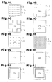
- the adhesive layer 13 in quadrilateral plate form may be formed in the four corners of the polymer layer 12, or as shown in Fig. 9D , the adhesive layer 13 in quadrilateral plate form may be formed in the center portion of the polymer layer 12.
- the intervals between the pieces in the adhesive layer 13 may be changed appropriately.
- Fig. 9B and 9C for example, the adhesive layer 13 in quadrilateral plate form may be formed in the four corners of the polymer layer 12, or as shown in Fig. 9D , the adhesive layer 13 in quadrilateral plate form may be formed in the center portion of the polymer layer 12.
- the intervals between the pieces in the adhesive layer 13 may be changed appropriately.
- Fig. 9E and 9F the intervals between the pieces in the adhesive layer 13 may be changed appropriately.
- an adhesive layer 13 in disc form may be formed in the four corners of the polymer layer 12, or as shown in Fig. 9H , the adhesive layer 13 in band form may be formed in a peripheral portion of the polymer layer 12.
- the width of the adhesive layer 13 in square annular form may be changed appropriately.
- the adhesive layer 13 may be formed in the center portion of the polymer layer 12, it is preferable for it to be formed in the peripheral portion of the polymer layer 12, and it is more preferable for it to be formed in annular form in the entire peripheral portion of the polymer layer 12.
- the amount of heat emitted from the center portion of the heat emitting body 22 is usually greater than the amount of heat emitted from the peripheral portion of the heat emitting body 22, and therefore, the temperature of the center portion of the heat emitting body 22 is high in comparison with the peripheral portion.
- the value of the thermal contact resistance in the peripheral portion of the polymer layer 12 attached to the heat emitting body 22 becomes high in comparison with the value of the thermal contact resistance in the center portion of the polymer layer 12. Therefore, the center portion of the polymer layer 12, of which the value of the thermal contact resistance is low in comparison with the peripheral portion, corresponds to the center portion of the heat emitting body 22, of which the temperature is high in comparison with the peripheral portion, and thus, the thermal conductivity of the sheet 11 can be increased in comparison with the case where the adhesive layer 13 is formed in the center portion of the polymer layer 12. Furthermore, the adhesive layer 13 is formed in annular form in the entire peripheral portion of the polymer layer 12, and thus, the thin and flexible polymer layer 12 can be prevented from bending, as in the case where the adhesive layer 13 is formed in multi-dot form.
- the peripheral portion of the polymer layer 12 is a region between the peripheral of the polymer layer 12 and 3/5 of the distance from the peripheral of the polymer layer 12 to the center.
- the peripheral portion of the polymer layer 12 is in quadrilateral annular form with a width of 24 mm.
- the peripheral portion of the polymer layer 12 is in annular form with a width of 12 mm.
- the end portions of the filler in fiber form 16a may not be exposed from the outer surfaces 12a of the polymer layer 12.
- the filler in fiber form 16a may not be oriented in one direction.
- the sheet 11 may further comprise the functional layer of another embodiment. That is to say, the functional layer that forms the sheet 11 may have a number of layers having different working effects. In this case, a number of layers that form the functional layer may be formed only on one outer surface 12a of the pair of outer surfaces 12a of the polymer layer 12, or the adhesive layer 13 may be formed on each outer surface 12a of the polymer layer 12, so that the adhesive layers are independently formed on the respective outer surfaces 12a of the polymer layer 12. In the case where the functional layer is formed of a number of layers, it is preferable for each layer to be thin, in order to prevent the value of the thermal contact resistance of the sheet from becoming high due to the thickness of the functional layer.
- the heat discharging body 25 may be omitted.
- the peripheral portion 17a of the conductive layer 17 is connected to a member having electrical conductance, for example the housing, in the second embodiment. In this configuration also, heat can be released from the surface of the polymer layer 12.
- the outer shape of the thermal diffusion layer 14 may be the same as the outer shape of the polymer layer 12, or smaller than the outer shape of the polymer layer 12.
- the sheet 11 may be placed on the heat emitting body 22 in such a manner that the polymer layer 12 faces the heat emitting body 22 when the sheet 11 is attached to the heat emitting body 22, for example.
- the heat discharging body 25 may not have electrical conductance.
- the peripheral portion 17a of the conductive layer 17 is connected to a member having electrical conductance, for example the housing.
- Example 1-a in the preparation step, carbon fibers, which are the filler in fiber form 16a, and alumina (aluminum oxide) in spherical form, which is the filler in particle form 16b, were mixed into addition type liquid silicone (hereinafter referred to as liquid silicone gel), which is the polymer matrix 15, so that a composition was prepared.
- liquid silicone gel solidified into a gel form after hardening.
- Table 1 shows the amount of each component mixed in.
- the unit for the blending quantity of each component in is mass parts.
- the viscosity of the liquid silicone gel at 25°C was 400 mPa ⁇ s, and the specific weight of the liquid silicone gel was 1.0.
- the average fiber diameter of the carbon fibers was 10 ⁇ m, and the average fiber length of the carbon fibers was 160 ⁇ m.
- the average particle diameter of the alumina in spherical form was 3.2 ⁇ m.
- the composition was stirred until the carbon fibers and alumina in spherical form were uniformly dispersed, and after that, bubbles were removed from the composition.
- the viscosity of the composition at 25°C was measured using a rotation viscometer, and after that, the die was filled with the composition.
- Table 1 shows the results of measurement for the viscosity.
- a superconductive magnet was used to apply a magnetic field having a magnetic flux density of 100,000 Gauss to the composition, and at the same time, compressed air was used to apply vibration with a frequency of 3.0 Hz and amplitude of 10 mm to the composition via the die, and thus, the carbon fibers were oriented in the direction of the thickness of the polymer layer.
- the composition was heated at 120°C for 90 minutes so that the liquid silicone gel hardened and the polymer layer 12 was obtained.
- a rotational cutter was used to remove a hardened silicone having a thickness of 5 ⁇ m from the paired outer surfaces 12a of the polymer layer 12, and thus, the carbon fibers were exposed.
- the thickness of the polymer layer 12 was 0.3 mm after the exposure step.
- a silicone based adhesive was applied over the entirety of the outer surfaces 12a of the polymer layer 12 in multi-dot form, and thus, the adhesive layer 13 in multi-dot form (thickness: 30 ⁇ m, diameter of each dot: 1.5 mm, interval between each dot: 7 mm) was formed.
- the thermal diffusion layer 14 made of a graphite sheet (thickness: 130 ⁇ m, made by GrafTech International Ltd.) was layered on top of the polymer layer 12 via the adhesive layer 13, so that the sheet 11 was gained.
- the sheet 11 was obtained in the same manner as in Example 1-a, except that the thickness of the adhesive layer 13 was changed to 50 ⁇ m.
- the sheet 11 was obtained in the same manner as in Example 1-a, except that the thickness of the adhesive layer 13 was changed to 60 ⁇ m.
- the sheet 11 was obtained in the same manner as in Example 1-a, except that an adhesive layer 13 (thickness: 30 ⁇ m, length of sides: 10 mm) was formed in the four corners of the polymer layer 12.
- the sheet 11 was obtained in the same manner as in Example 1-a, except that the adhesive layer 13 (thickness: 30 ⁇ m, length of sides: 12 mm) was formed in the four corners of the polymer layer 12.
- the sheet 11 was obtained in the same manner as in Example 1-a, except that the adhesive layer 13 (thickness: 30 ⁇ m, length of sides: 5 mm) was formed in the four corners of the polymer layer 12.
- Examples 2-a to 2-f PBO carbon fibers were used as a filler in fiber form, and at the same time, the amount of each component mixed in was changed as shown in Table 1, and furthermore, the silicone was removed in the exposure step, through polishing using a mesh made of metal.
- the polymer layer 12 was gained in the same manner as in Examples 1-a to 1-f.
- the outer surfaces 12a of the polymer layer 12 were observed through an electron microscope after the exposure step, it was confirmed that the PBO carbon fibers were exposed.
- the thus gained polymer layer 12 was cut into quadrilateral plate form (length of sides: 40 mm).
- the adhesive layer 13 was formed and the thermal diffusion layer 14 was layered on top of this, and thus, the sheet 11 was obtained.
- Example 2-a the adhesive layer 13 was formed in the same manner as in Example 1-a
- Example 2-b the adhesive layer 13 was formed in the same manner as in Example 1-b.
- Example 3-a as shown in Table 4, the sheet 11 was gained in the same manner as in Example 1-a.
- Example 3-b as shown in Table 4, the sheet 11 was obtained in the same manner as in Example 3-a, except that the thickness of the thermal diffusion layer 14 was changed to 80 ⁇ m.
- Example 3-c the sheet 11 was obtained in the same manner as in Example 3-a except that the thickness of the thermal diffusion layer 14 was changed to 250 ⁇ m.
- Example 3-d the sheet 11 was gained in the same manner as in Example 3-a, except that the thickness of the thermal diffusion layer 14 was changed to 375 ⁇ m.
- Comparative Example 1-a a sheet was gained in the same manner as in Example 1-a, except that there was no adhesive layer 13 and thermal diffusion layer 14.
- Comparative Example 1-b a sheet was obtained in the same manner as in Example 1-a, except that the adhesive layer 13 was formed throughout the entirety of the outer surface 12a of the polymer layer 12.
- Comparative Example 2-a a sheet was obtained in the same manner as in Example 2-a, except that there was no adhesive layer 13 and thermal diffusion layer 14.
- Comparative Example 2-b a sheet was obtained in the same manner as in Example 2-a, except that the adhesive layer 13 was formed throughout the entirety of the outer surface 12a of the polymer layer 12.
- Test pieces in disc form (diameter: 10 mm, thickness: 0.3 mm) were obtained from the polymer layer 12 in each example, and after that, the thermal conductivity of the test pieces was measured in accordance with a laser flash method.
- the test piece 27 made of the sheet in each example or comparative example and the heat discharging body 25 made of a metal were mounted on top of the heat emitting body 22 formed on a substrate 21 in this order, and a weight 28 of 10 kg was placed on the heat discharging body 25, so that a load of 6.1 ⁇ 10 4 Pa was applied to the test piece 27. Then, this was left for 10 minutes in such a state that the heat emitting body 22 was emitting heat, and after that, the temperature T 1 of the outer surface on the heat emitting body 22 side and the temperature T 2 of the outer surface on the heat discharging body 25 side in the test piece 27 were measured using the measuring machine 28a.
- the heat emitting body 22 is usually an electronic part, such as a CPU, and a heater of which the amount of heat emitted is 100 W was used as the heat emitting body 22 in the present test, in order to simplify and expedite the evaluation of the performance of the sheet.
- the value of the above described load indicates the size of the load usually applied to the sheet when the sheet is attached to an electronic part.
- Value of thermal resistance °C / W Ti ( °C ) - T 2 °C / amount of heat emitted W
- a test piece 30 made of the polymer layer in each example was placed on the horizontal table 29, and after that, the sliding piece 31 and the weight 28 of 120 g (columnar form, with a diameter of 28 mm and height of 25 mm) were placed on this test piece 30 in this order.
- the push-pull gauge 33 (CPU gauge M-9500, made by Aikoh Engineering Co., Ltd.).
- the push-pull gauge 33 was pulled in the direction parallel to the outer surface of the test piece 30 at a speed of 100 mm/min.
- the static frictional force Fs (N) between the test piece and the sliding piece 31 when the push-pull gauge 33 is pulled was measured.
- the coefficient of static friction was calculated using the following formula (2).
- the measurement of the static frictional force Fs and the calculation of the coefficient of static friction were repeated five times for the polymer layer 12 in each example and comparative example, and the average value for these values of the coefficient of static friction was taken to be the coefficient of static friction of the polymer layer 12.
- two types of sliding pieces 31 a PET film (Lumirror S10, made by Toray Industries Inc., thickness: 75 ⁇ m) and an aluminum foil tape (Scotch Brand Tape 433 HD, made by Sumitomo 3M Limited) were used.
- the aluminum foil tape was placed on the test piece 30 so that the aluminum foil surface of the tape faced the test piece 30.
- Coefficient of static friction Fs N / Fp N
- the adhesiveness of the polymer layer 12 in each example and comparative example was measured in accordance with JIS Z 0237. Concretely, as shown in Fig. 12 , the film 34 was secured to the surface of the horizontal table 29, and after that, the test piece 30 in each example comparative example was placed on top of this. Then, one end of the test piece 30 was fixed to the load cell 35 of the tensile test machine. Then, the load when the test piece 30 is pulled and peeled along a line perpendicular to the horizontal table 29 at a speed of 300 mm/min was measured. Here, the measurement of the load for the test piece in each example comparative example was repeated five times, and the average value of these measured values was taken to be the adhesiveness of the polymer layer 12.
- the film 34 two types of film were used: a PET film (Lumirror S10, made by Toray Industries Inc., thickness: 75 ⁇ m) and an aluminum foil tape (Scotch Brand Tape 433 HD, made by Sumitomo 3M Limited).
- the aluminum foil tape was secured to the horizontal table 29 so that the aluminum foil surface of the tape faced the test piece 30.
- the column “adhesiveness (for aluminum) (N/25 mm)” in Table 1 indicates the results of measurement for the adhesiveness in the case where the aluminum foil tape was used, while the column “adhesiveness (for PET) (N/25 mm)” indicates the results of measurement for the adhesiveness in the case where the PET film was used. In these columns, "-" indicates that the adhesiveness was too small to be measured in accordance with the above describe method.
- the test piece 27 made of the sheet in each example comparative example was placed in the center of a ceramic heater (heat source) having sides of 10 mm, so that the polymer layer 12 made contact with the ceramic heater, and after that, the temperature of the test piece 27 was measured using a thermoviewer.
- the voltage applied to the ceramic heater was set to 10 V.
- Tables 2 to 4 In the column “properties in terms of thermal diffusion” in Tables 2 to 4, "o” indicates that the heat from the heat source diffused throughout approximately the entirety of the test piece 27, and "x” indicates that the heat from the heat source was concentrated in a portion of the test piece 27.
- Fig. 13A shows the results of measurement for the temperature of the test piece 27 in Example 1-a, and Fig.
- Example 13B shows the results of measurement for the temperature of the test piece 27 in Comparative Example 1-a.
- Table 1 Examples 1 and 3 Example 2 Liquid silicone (amount mixed in) 100 100 Carbon fibers Average fiber length ( ⁇ m) 120 160 120 200 Alumina 475 500 Viscosity (25°C, 1.0 rpm) mPa ⁇ s 600,000 1,100,000 Magnetic field Yes Yes Vibration Frequency: 3.0 Hz Amplitude: 10 mm Frequency: 3.0 Hz Amplitude: 10 mm Exposure step Yes Yes Filler in fiber form in crosswise direction (%) 70 70 Ease of handling ⁇ ⁇ Thermal conductivity (W/m -K) 30 50 Coefficient of static friction (for aluminum) 0.134 0.129 Coefficient of static friction (for PET) 0.170 0.166 Adhesiveness (for aluminum)(N/25 mm) - - Adhesiveness (for PET)(N/25 mm) - - - -
- the value of the thermal resistance for the sheets 11 according to Examples 1-a and 2-a were each lower than the value of the thermal resistance for the sheets 11 according to Examples 1-c and 2-c. That is to say, the thickness of the adhesive layers 13 in Examples 1-c and 2-c was as great as 60 ⁇ m, and therefore, the value of the thermal contact resistance was higher than for the sheets 11 in Examples 1-a and 2-a.
- the value of the thermal resistance for the sheets 11 in Examples 1-d and 2-d were each lower than the value of the thermal resistance for the sheets 11 in Examples 1-f and 2-f.
- the ratio of the area of the polymer layer 12 occupied by the adhesive layer 13 to the area of the entirety of one outer surface 12a to which the adhesive layer 13 is attached was high in Examples 1-d and 2-d in comparison with Examples 1-f and 2-f, respectively.
- the adhesive layer 13 is formed in the peripheral portion of the polymer layer 12, and thus, it was found that the value of the thermal contact resistance of the sheet 11 can be decreased in comparison with the case where the adhesive layer 13 is formed in the center portion of the polymer layer 12.
- Comparative Examples 1-a and 2-a there was no thermal diffusion layer 14, and therefore, the properties in terms of thermal diffusion received a low evaluation.
- the adhesive layer 13 was formed throughout the entirety of the polymer layer 12, and therefore, the value of the thermal contact resistance for the sheet became high.
- heat did not diffuse in Comparative Example 1-a, and the temperature in the center portion was 200°C or higher.
- Example 4-a as shown in Table 5, the sheet 11 was obtained in the same manner as in Example 3-a, except that the thermal diffusion layer 14 was changed to the conductive layer 17 made of an aluminum foil (thickness: 12 ⁇ m).
- Example 4-b as shown in Table 5, the sheet 11 was obtained in the same manner as in Example 4-a, except that the aluminum foil was changed to a copper foil (thickness: 8 ⁇ m).
- Example 4-c as shown in Table 5, the sheet 11 was obtained in the same manner as in Example 4-a, except that the aluminum foil was changed to a copper foil (thickness: 12 ⁇ m).
- Example 4-d as shown in Table 5, the sheet 11 was obtained in the same manner as in Example 4-a, except that the aluminum foil was changed to a copper foil (thickness: 18 ⁇ m).
- the volume resistivity ( ⁇ cm) of the conductive layer 17 in the sheet 11 was measured using a resistivity meter (MCP-T500, made by Dia Instruments Co., Ltd.) in accordance with JIS K 7194.
- the sheet 11 in each example had excellent thermal conductivity and electrical conductivity.
- the sheet 11 in each example had a low adhesiveness on the polymer layer 12, and thus, was very easy to handle.
- Example 5-a as shown in Table 6, the sheet 11 was obtained in the same manner as in Example 3-a, except that the thermal diffusion layer 14 was changed to the electrically insulating layer 18 made of a PET film (thickness: 5 ⁇ m).
- Example 5-b as shown in Table 6, the sheet 11 was obtained in the same manner as in Example 3-a, except that the PET film was changed to a polyolefin film (thickness: 12 ⁇ m).
- Example 5-c as shown in Table 6, the sheet 11 was obtained in the same manner as in Example 3-a, except that the PET film was changed to a PVC film (thickness: 5 ⁇ m).
- Comparative Example 5-a as shown in Table 6, a sheet was obtained in the same manner as in Example 5-a, except that the adhesive layer 13 (thickness: 10 ⁇ m) was formed throughout the entirety of the outer surface of the polymer layer 12.
- the dielectric breakdown voltage (kV) of the sheet was measured using a withstand voltage testing machine (TOS8650, made by Kikusui Electronics Corporation) in accordance with JIS C 2110 (IEC 243, which is an international standard).
- TOS8650 made by Kikusui Electronics Corporation
- JIS C 2110 IEC 243, which is an international standard.
- the dielectric breakdown voltage indicates the voltage when a current flows through an electrical insulating sample when the sample is sandwiched between two electrodes and then the voltage is gradually increased to such a point that the current increases dramatically and a portion of the sample is melted and carbonized, or a hole is created.
- the sheet 11 in each example had excellent thermal conductivity and electrical insulating properties.
- the sheet 11 in each example had a low adhesiveness for the polymer layer 12, and thus, was very easy to handle.
- the adhesive layer 13 is formed throughout the entirety of the polymer layer 12, and therefore, the value of the thermal resistance became high.
Abstract
Description
- The present invention relates to a thermally conductive sheet used to release heat generated by semiconductor devices and various types of electronic parts which are heat emitting bodies and a method of manufacturing the same.
- Thermally conductive sheets, thermally conductive grease, thermally conductive adhesives, phase change members having thermal conductivity and the like are inserted between heat emitting bodies mounted on circuit boards for conventional electronics and heat discharging bodies in order to release heat generated by the heat emitting bodies. Specific examples of heat emitting bodies include semiconductor devices and electronic parts. Specific examples of heat discharging bodies include heat sinks and cooling fans. In recent years, the power consumption and amount of heat emission of electronic parts have increased as the functions and performance of electronics have increased. In addition, the space within the housing of electronics for arranging members, such as circuit boards, has been becoming smaller as the scale and the thickness of electronics have been reduced. When heat accumulates in electronic parts, for example, the processing performance in the electronic parts decreases, it becomes easy for the electronic parts to be damaged, and the higher temperature is unpleasant for the user of the electronic device. Thus, it is necessary to avoid heat accumulation in heat emitting bodies, for example in electronic parts and the like, and cooling of heat emitting bodies has become an important goal. Therefore, excellent thermal conductivity is required for thermally conductive sheets and the like.
- In addition, thermal diffusion sheets formed of graphite or a metal material, for example, are used in order to effectively diffuse heat generated by a heat emitting body within the limited space inside the housing. In particular, it is necessary to avoid local heat accumulation in mobile devices of which the scale and thickness are small and where the density of heat emission is high. Thus, a thermal diffusion sheet having excellent properties in terms of thermal diffusion has been required. In the case where a thermal diffusion sheet makes direct contact with a heat emitting body, the thermal diffusion sheet does not stick to the shape of the contour of the heat emitting body, due to the high rigidity of the graphite or metal material that forms the thermal diffusion sheet. Therefore, the thermal diffusion sheet cannot make sufficiently close contact with the heat emitting body, and thus, excellent properties in terms of thermal diffusion cannot be gained.
- Japanese Laid-Open Patent Publication No.
2003-168882 2005-57088 2004-243650 - An object of the present invention is to provide a thermally conductive sheet which is more appropriate for use in applications where heat release from heat emitting bodies is required. The present invention also relates to a method of manufacturing the thermally conductive sheet.
- To achieve the foregoing and in accordance with a first aspect of the present invention, a thermally conductive sheet is provided. The thermally conductive sheet includes a thermally conductive polymer layer formed of a thermally conductive polymer composition, an adhesive layer provided on an outer surface of the thermally conductive polymer layer, and a functional layer provided on the adhesive layer. The thermally conductive polymer composition contains a polymer matrix and a thermally conductive filler. The coefficient of static friction of the thermally conductive polymer layer is 1.0 or lower. The adhesive layer and the thermally conductive polymer layer each have an outer shape and the outer shape of the adhesive layer is smaller than the outer shape of the thermally conductive polymer layer.
- In accordance with a second aspect of the present invention, a method for manufacturing a thermally conductive sheet is provided. The method includes: forming a thermally conductive polymer layer of a thermally conductive polymer composition containing a polymer matrix and a thermally conductive filler in which the coefficient of static friction of the thermally conductive polymer layer is 1.0 or lower and the thermally conductive polymer layer includes an outer shape; providing an adhesive layer on an outer surface of the thermally conductive polymer layer in which the adhesive layer has an outer shape smaller than the outer shape of the thermally conductive polymer layer; and providing a functional layer on the adhesive layer.
- The invention, together with objects and advantages thereof, may best be understood by reference to the following description of the presently preferred embodiments together with the accompanying drawings in which:
-
Fig. 1A is a plane diagram showing a first embodiment of a thermally conductive sheet in accordance with the present invention; -
Fig. 1B is a cross sectional diagram alongline 1B-1B ofFig. 1A ; -
Fig. 1C is an enlarged cross sectional diagram showing a polymer layer; -
Fig. 2 is a cross sectional diagram showing the step of manufacturing a thermally conductive sheet; -
Fig. 3A is a cross sectional diagram showing the attachment of a thermally conductive sheet to a heat emitting body; -
Fig. 3B is an enlarged cross sectional diagram showing a thermally conductive polymer layer and a heat discharging body; -
Fig. 3C is an enlarged cross sectional diagram showing a thermally conductive polymer layer and a thermal diffusion layer; -
Fig. 4A is a cross sectional diagram showing the thermally conductive sheet according to a second embodiment; -
Fig. 4B is a cross sectional diagram alongline 4B-4B ofFig. 4A ; -
Fig. 4C is an enlarged cross sectional diagram showing a polymer layer; -
Fig. 5 is a cross sectional diagram showing the attachment of a thermally conductive sheet to a heat emitting body; -
Fig. 6A is a cross sectional diagram showing the thermally conductive sheet according to a third embodiment; -
Fig. 6B is a cross sectional diagram alongline 6B-6B ofFig. 6A ; -
Fig. 6C is an enlarged cross sectional diagram showing a polymer layer; -
Fig. 7A is a plane diagram showing the thermally conductive sheet according to the fourth embodiment; -
Fig. 7B is a cross sectional diagram alongline 7B-7B ofFig. 7A ; -
Fig. 8A is a plane diagram showing another example of the thermally conductive sheet; -
Fig. 8B is a cross sectional diagram alongline 8B-8B ofFig. 8A ; -
Figs. 9A to 9J are plane diagrams showing an adhesive layer and other examples thereof in accordance with examples of the invention; -
Fig. 10 is a schematic diagram illustrating a method for measuring the value of the thermal resistance in the polymer layer; -
Fig. 11 is a schematic diagram illustrating a method for measuring the coefficient of static friction in the polymer layer; -
Fig. 12 is a schematic diagram illustrating a method for measuring the adhesiveness of the polymer layer; -
Fig. 13A is a photograph showing the temperature distribution in the test piece according to Example 1-a; and -
Fig. 13B is a photograph showing the temperature distribution in the test piece according to Comparative Example 1-a. - In the following, first embodiment of a thermally conductive sheet in accordance with the present invention is described with reference to the drawings. As shown in
Figs. 1A to 1C , the thermallyconductive sheet 11 according to the present embodiment comprises a thermallyconductive polymer layer 12 formed of a thermally conductive polymer composition, anadhesive layer 13 formed on theouter surface 12a of the thermallyconductive polymer layer 12, and athermal diffusion layer 14, which is a functional layer formed on theadhesive layer 13. The layers are in the order of:thermal diffusion layer 14,adhesive layer 13, thermallyconductive polymer layer 12, from the bottom. In the following description, the thermallyconductive sheet 11 is simply referred to assheet 11, the thermally conductive polymer composition is simply referred to as composition, and the thermallyconductive polymer layer 12 is simply referred to aspolymer layer 12. Thesheet 11 is inserted between a heat emitting body and a heat discharging body, for example, for use, so that heat is discharged from the hot heat emitting body and the heat emitting body is cooled. - The
sheet 11 is provided with a cooling function and is easy to handle. The cooling function is an index for ease of cooling a hot heat emitting body, and based on the thermal conductivity of thepolymer layer 12 and the properties of thethermal diffusion layer 14 in terms of thermal diffusion. That is to say, the cooling function is based on the thermal conductivity of thepolymer layer 12, the value of the thermal resistance of thepolymer layer 12, the adhesion between the heat emitting body or heat discharging body and thepolymer layer 12, as well as that between thethermal diffusion layer 14 and thepolymer layer 12, and the properties of thethermal diffusion layer 14 in terms of thermal diffusion. The higher the thermal conductivity of thepolymer layer 12 is, the smaller the value of the thermal resistance of thepolymer layer 12 is, the stronger the adhesion between the heat emitting body or heat discharging body and thepolymer layer 12, as well as that between thethermal diffusion layer 14 and thepolymer layer 12, is, and the better the properties of thethermal diffusion layer 14 in terms of thermal diffusion are, the better the cooling function of thesheet 11. - The ease of handling is an index for the ease of handling when the
sheet 11 is carried and the like, and mainly based on the adhesiveness of thepolymer layer 12. The smaller the adhesiveness of thepolymer layer 12, the easier thesheet 11 is to handle when carried, and thus, the ease of handling is high. - The composition contains a polymer matrix and a thermally conductive filler. The polymer matrix holds the thermally conductive filler within the
polymer layer 12. The polymer matrix is selected in accordance with the performance required for thepolymer layer 12, for example mechanical strength, hardness, durability, resistance to heat, and electrical properties. Specific examples of the polymer matrix include silicone resin. - The thermally conductive filler increases the thermal conductivity of the
polymer layer 12 so that the cooling function of thesheet 11 increases. Specific examples for the form of the thermally conductive filler include fiber, particle, and plate forms. Preferably, at least part of the thermally conductive filler is in fiber form. In the following, a thermally conductive filler in fiber form, that is to say, asheet 11 containing a filler in fiber form, is described. Specific examples of the filler in fiber form include carbon fibers and poly(p-phenylenebenzobisoxazole) precursor carbon fibers (PBO carbon fibers). Specific examples of materials for thermally conductive fillers having a form other than fiber form, that is to say, fillers in non-fiber form include aluminum oxide and aluminum hydroxide. - It is preferable for the thermally conductive filler content in the composition to be 90 mass % or less. In the case where the thermally conductive filler content exceeds 90 mass %, the
polymer layer 12 becomes fragile, because the flexibility of thepolymer layer 12 is low, and at the same time, there is a risk that thepolymer layer 12 may not stick to the shape of the contour of the heat emitting body and the heat discharging body as much. The composition may contain a plasticizer for adjusting the hardness of, for example, thepolymer layer 12, and a stabilizer for enhancing the durability, in addition to the above described components. - The
polymer layer 12 is in quadrilateral form and accelerates thermal conduction from the heat emitting body to the heat discharging body so that the hot heat emitting body is cooled. Thepolymer layer 12 is provided with apolymer matrix 15 and a thermallyconductive filler 16. The thermallyconductive filler 16 according to the present embodiment has a thermallyconductive filler 16 in fiber form, that is to say, filler infiber form 16a and a thermallyconductive filler 16 in particle form, that is to say, a filler inparticle form 16b. The filler infiber form 16a is oriented in one direction. In thepolymer layer 12 shown inFigs. 1B and 1C , for example, the filler infiber form 16a is oriented in the direction of the thickness of thepolymer layer 12. Therefore, the value of the thermal conductivity of thepolymer layer 12 in the direction of the thickness is equal to the value gained by multiplying the value of the thermal conductivity in the direction of the width by two to several hundred. The end portions of the filler infiber form 16a extend in the direction of the width of thepolymer layer 12 and are exposed on pairs of facingouter surfaces 12a. - The adhesiveness of the
polymer layer 12 is very small, and therefore, the adhesiveness of thepolymer layer 12 can be indicated using the coefficient of static friction of thepolymer layer 12. That is to say, in the case where the coefficient of static friction of thepolymer layer 12 is low, the adhesiveness of thepolymer layer 12 is low, while in the case where the coefficient of static friction of thepolymer layer 12 is high, the adhesiveness of thepolymer layer 12 is high. The coefficient of static friction of thepolymer layer 12 is 1.0 or lower, preferably 0.3 or lower. In the case where the coefficient of static friction of thepolymer layer 12 exceeds 1.0, it becomes difficult to attach thesheet 11 to the heat emitting body, for example, due to excessively high adhesiveness of thepolymer layer 12. The lower limit for the coefficient of static friction of thepolymer layer 12 is not particularly limited, and the smaller the coefficient of static friction of thepolymer layer 12 is, the easier it is to attach thesheet 11 to the heat emitting body, for example. In the case where the coefficient of static friction of thepolymer layer 12 is 1.0 or lower, thepolymer layer 12 is not sticky when theouter surfaces 12a of thepolymer 12 are touched with the fingers, and thus, thepolymer layer 12 does not adhere to thethermal diffusion layer 14 through its own adhesiveness. - The thickness of the
polymer layer 12 is preferably 0.03 mm to 0.5 mm. In the case where the thickness of thepolymer layer 12 is less than 0.03 mm, the manufacture of thepolymer layer 12 becomes difficult. In the case where the thickness of thepolymer layer 12 exceeds 0.5 mm, it takes time for the heat to conduct from the heat emitting body to the heat discharging body, and there is a risk that the cooling function of thesheet 11 may deteriorate. Polymer layers 12 having a thickness of 0.5 mm or less easily become flexible, due to the material. - The hardness of the
polymer layer 12 as measured in accordance with the type E of JIS K 6253, which is a Japanese Industrial Standard (ISO 7619-1, which is an international standard), is 5 to 80, for example. In the case where the hardness of thepolymer layer 12 is less than 5, thepolymer layer 12 is too flexible, and therefore, the ease of handling of thesheet 11 deteriorates. Thus, it becomes difficult to handle thesheet 11. In the case where the hardness of thepolymer layer 12 exceeds 80, the adhesion between thepolymer layer 12 and the heat emitting body or heat discharging body decreases, and there is a risk that the cooling function of thesheet 11 may deteriorate. - The outer shape of the
adhesive layer 13 is smaller than the outer shape of thepolymer layer 12, and in multi-dot form throughout the entirety of theouter surfaces 12a of thepolymer layer 12. Theadhesive layer 13 holds thepolymer layer 12 and thethermal diffusion layer 14 together through theadhesive layer 13. - Specific examples of the material for the
adhesive layer 13 include acryl based, silicone based, urethane based, vinyl based and synthetic rubber based gluing agents and adhesives. Theadhesive layer 13 is formed through application of a material for forming theadhesive layer 13 to thepolymer layer 12. Furthermore, theadhesive layer 13 may be formed of an adhesive tape where the above described adhesive is applied to a polymer film, which has the same effects. In addition, thepolymer layer 12 easily adheres to thethermal diffusion layer 14, and therefore, it is preferable for the material for theadhesive layer 13 to have flexibility. - The ratio of the area occupied by the
adhesive layer 13 to the entirety of theouter surfaces 12a on theouter surfaces 12a to which theadhesive layer 13 of thepolymer layer 12 is attached is preferably 30% or less. The thermal conductivity of theadhesive layer 13 and the properties of theadhesive layer 13 in terms of thermal diffusion are poor in comparison with the thermal conductivity of thepolymer layer 12 and the properties of thethermal diffusion layer 14 in terms of thermal diffusion. Therefore, when the ratio of the area occupied by theadhesive layer 13 exceeds 30%, there is a risk that the cooling function of thesheet 11 may deteriorate excessively. - The thickness of the
adhesive layer 13 is preferably 50 µm or less. In the case where the thickness of theadhesive layer 13 exceeds 50 µm, the difference between the outer surface of thepolymer layer 12 and the surface of theadhesive layer 13 becomes great due to the thickness of theadhesive layer 13. Therefore, there is a risk that the adhesion between thepolymer layer 12 and thethermal diffusion layer 14 may decrease, and the value of the thermal contact resistance of thesheet 11 may become high when thesheet 11 is attached to a heat emitting body, for example. As described above, the thermal conductivity of theadhesive layer 13 is poor in comparison with the thermal conductivity of thepolymer layer 12. Thus, the lower limit for the thickness of theadhesive layer 13 is not particularly limited, and the thinner theadhesive layer 13, the higher the adhesion between thepolymer layer 12 and thethermal diffusion layer 14 becomes, and the lower the ratio of theadhesive layer 13 in the direction of the thermal conductance in thesheet 11 becomes. Thus, the lower the value of the thermal contact resistance of thesheet 11 becomes. - The
thermal diffusion layer 14 is in quadrilateral form and allows heat to diffuse from the hot heat emitting body, and thus, prevents heat from accumulating within the heat emitting body and in the vicinity of the heat emitting body, so that the cooling function of thesheet 11 improves. Thethermal diffusion layer 14 is formed of a graphite sheet or a sheet made of a metal, for example. Specific examples of the material for the sheet made of a metal include copper and aluminum. Thethermal diffusion layer 14 allows heat to diffuse in the direction parallel to the surface, due to the quality of the material, and releases diffused heat to the outside from the peripheral and the surface of thethermal diffusion layer 14. Therefore, thethermal diffusion layer 14 is preferably formed of a graphite sheet. Graphite sheets usually have high thermal conductivity in the direction parallel to the surface, in comparison with the thermal conductivity in the direction of the thickness. Concretely, the thermal conductivity in the direction parallel to the surface of the graphite sheet is 100 W/m-K to 800 W/m-K. The graphite sheet allows heat to diffuse in such a manner as to be conveyed more quickly in the direction parallel to the surface than in the direction of the thickness. - As shown in
Figs. 1A and 1B , the outer shape of thethermal diffusion layer 14 is larger than the outer shape of thepolymer layer 12, and theperipheral portion 14a of thethermal diffusion layer 14 is exposed. The thickness of thethermal diffusion layer 14 is preferably 10 µm to 150 µm. In the case where the thickness of thethermal diffusion layer 14 is less than 10 µm, thethermal diffusion layer 14 is fragile and easily damaged, and the thermal capacity of thethermal diffusion layer 14 is excessively small, and therefore there is a risk that the cooling function of thesheet 11 may not improve sufficiently. In the case where the thickness of thethermal diffusion layer 14 exceeds 150 µm, there is a risk that the efficiency of thermal conduction from the heat emitting body to the heat discharging body may decrease, due to the excessive thickness of thethermal diffusion layer 14. - The
sheet 11 is manufactured through a preparation step of preparing a composition, an orientation step of orienting the filler infiber form 16a, a formation step of forming apolymer layer 12, an exposure step of exposing the filler infiber form 16a, and a laminating step of laminating anadhesive layer 13 and athermal diffusion layer 14 on thepolymer layer 12 in this order. - In the preparation step, the appropriate components described above are mixed, so that a composition is prepared. In the orientation step, a die, for example, is filled with the composition, and after that, the filler in
fiber form 16a is oriented. As the method for orienting the filler infiber form 16a, a method for applying a magnetic field in the composition using a magnetic field generating apparatus and a method for applying vibration in the composition using a vibration apparatus can be used, and a method for applying both a magnetic field and vibration to the composition is preferable, because the filler infiber form 16a is easily oriented. At this time, the magnetic field and vibration are applied to the filler infiber form 16a via the composition. - In the formation step, the
polymer matrix 15 is hardened or solidified within the die in such a state that the orientation of the filler infiber form 16a is maintained, and thus, apolymer layer 12 in predetermined form is formed. As shown inFig. 2 , the filler infiber form 16a in thepolymer layer 12 after the formation step is not exposed from theouter surface 12a of thepolymer layer 12. In the exposure step, a blade in mesh form, for example, is pressed against theouter surface 12a of thepolymer layer 12, and after that, is slid over theouter surface 12a, and thus, thepolymer matrix 15 is removed from theouter surface 12a, so that the filler infiber form 16a is exposed from theouter surface 12a. In the laminating step, a material for forming anadhesive layer 13 is applied in a predetermined location on theouter surface 12a of thepolymer layer 12 in accordance with a well-known method, and thus, theadhesive layer 13 is layered in multi-dot form on theouter surface 12a of thepolymer layer 12. Next, athermal diffusion layer 14 is layered on theadhesive layer 13. - When the
sheet 11 is attached to the heat emitting body and the heat discharging body, as shown inFig. 3A , thesheet 11 is placed on top of the heat emitting body 22 (for example an electronic device) provided on asubstrate 21, for example. At this time, thethermal diffusion layer 14 faces theheat emitting body 22. The bottom of theheat emitting body 22 is covered with an electrically insulatinglayer 23, andterminals 24 for connecting theheat emitting body 22 to an electrical circuit, not shown, on thesubstrate 21 are provided between thesubstrate 21 and the electrically insulatinglayer 23. Subsequently, theheat discharging body 25 is placed on top of thesheet 11, and after that, a load is applied from theheat discharging body 25 to theheat emitting body 22 so that thesheet 11 makes close contact with theheat emitting body 22 and theheat discharging body 25, and thus, thesheet 11 is sandwiched between theheat emitting body 22 and theheat discharging body 25. At this time, as shown inFigs. 3B and 3C , the end portions of the filler infiber form 16a exposed from the outer surface of thepolymer layer 12 are pressed into thepolymer layer 12 as a result of the above described load. Furthermore, thepolymer matrix 15 soaks out from between the exposed filler infiber form 16a as a result of the above described load. Therefore, the above described exposed filler infiber form 16a is relatively immersed in thepolymer matrix 15 within thepolymer layer 12, so that the adhesiveness of thepolymer layer 12 increases. Furthermore, thepolymer layer 12 makes close contact with thethermal diffusion layer 14 and theheat discharging layer 25 without creating a gap between thethermal diffusion layer 14 and the dischargingbody 25. The value of the load applied to theheat discharging body 25 is, for example, 4.9 N. - The above described embodiment has the following advantages.
- The
sheet 11 according to the present embodiment comprises apolymer layer 12 and athermal diffusion layer 14 layered on top of thepolymer layer 12 via anadhesive layer 13. Therefore, thesheet 11 allows heat from theheat emitting body 22 to diffuse through thethermal diffusion layer 14, and accelerates thermal conduction from theheat emitting body 22 to theheat discharging body 25 through thepolymer layer 12, and thus, an excellent cooling function can be gained. - The coefficient of static friction of the
polymer layer 12 is set to 1.0 or lower, and thepolymer layer 12 and thethermal diffusion layer 14 are integrally formed using theadhesive layer 13. Therefore, the adhesiveness of thepolymer layer 12 decreases, so that ease of handling of thesheet 11 can be increased and thethermal diffusion layer 14 can be attached to thepolymer layer 12 having low adhesiveness without fail. - The outer shape of the
adhesive layer 13 is smaller than the outer shape of thepolymer layer 12, and theadhesive layer 13 according to the present embodiment is in multi-dot form throughout the entirety of theouter surface 12a of thepolymer layer 12. Therefore, the cooling function of thesheet 11 can be prevented from deteriorating, due to theadhesive layer 13, in comparison with the case where theadhesive layer 13 is formed on the entirety of theouter surface 12a of thepolymer layer 12. Furthermore, the ratio of the area occupied by theadhesive layer 13 to the entirety of theouter surface 12a can be set to 30% or lower on theouter surface 12a of thepolymer layer 12, where theadhesive layer 13 is provided, and thus, the cooling function of thesheet 11 can be prevented from deteriorating due to theadhesive layer 13 without fail. - In the case where the
adhesive layer 13 is formed in only part of the peripheral portion of thepolymer layer 12, for example, there is a risk that a thin andflexible polymer layer 12 may bend toward thethermal diffusion layer 14 or outward in portions where the adhesive layer is not formed. In this case, attachment of the sheet to theheat emitting body 22, for example, becomes difficult. In contrast, according to the present embodiment, theadhesive layer 13 is formed uniformly throughout the entirety of thepolymer layer 12, and therefore, the thin andflexible polymer layer 12 can be prevented from bending. - When the thickness of the
adhesive layer 13 is set to 50 µm or less, the value of the thermal contact resistance of thesheet 11 can be decreased, so that the cooling function of thesheet 11 increases. - The
peripheral portion 14a of thethermal diffusion layer 14 is exposed. Therefore, heat can easily diffuse from theperipheral portion 14a. - The thickness of the
thermal diffusion layer 14 is set to 10 µm to 150 µm, and thus, the cooling function of thesheet 11 can be increased sufficiently. - Next, a
sheet 11 according to a second embodiment in accordance with the present invention is described with reference to the drawings. In the second embodiment, the same symbols are attached to members which are the same as in the first embodiment, and the descriptions thereof are omitted, and descriptions for operational effects that are the same as in the first embodiment are also omitted. - As shown in
Figs. 4A to 4C , thesheet 11 according to the present embodiment comprises apolymer layer 12, anadhesive layer 13 and aconductive layer 17, which is a functional layer formed on top of theadhesive layer 13. The layers are in the order of:conductive layer 17,adhesive layer 13,polymer layer 12, from the bottom. Thesheet 11 is inserted between a heat emitting body and a heat discharging body, for example, for use, and accelerates heat conduction from the heat emitting body to the heat discharging body. - The
sheet 11 has high thermal conductivity and a high conductivity, and is easy to handle. The thermal conductivity is an indicator for ease of thermal conductance from theheat emitting body 22 to theheat discharging body 25, and depends mainly on the thermal conductivity and the thermal resistivity of thepolymer layer 12, as well as the adhesion between theheat discharging body 25 and thepolymer layer 12, as well as that between theconductive layer 17 and thepolymer layer 12. The higher the thermal conductivity of thepolymer layer 12 is, the smaller the value of the thermal resistance is, and the higher the adhesion between theheat discharging body 25 and thepolymer layer 12, as well as that between theconductive layer 17 and thepolymer layer 12, is, the higher thermal conductivity thesheet 11 has. The conductivity is an index for the ease with which a current flows from theheat emitting body 22 to theheat discharging body 25 having a high conductivity, and mainly depends on the material for theconductive layer 17. The ease of handling is an indicator for the ease of handling when thesheet 11 is carried, and mainly depends on the adhesiveness of thepolymer layer 12. Thesheet 11 becomes easier to handle when carried as the adhesiveness of thepolymer layer 12 becomes smaller. - The
conductive layer 17 allows a current to flow from theheat emitting body 22 to theheat discharging body 25 having a high conductivity, and thus, prevents electrostatic discharge (ESD) due to charging of theheat emitting body 22. Theconductive layer 17 is formed of a sheet having a high conductivity, for example a sheet made of a metal, and a conductive resin sheet or a conductive sheet. Specific examples of the material for the sheet made of a metal include copper and aluminum. The conductive resin sheet is provided with, for example, a thermoplastic resin or a thermosetting resin and conductive particles dispersed therein. The conductive sheet is formed by coating the thermoplastic resin sheet, for example, with a metal layer. - As shown in
Figs. 4A and 4B , the outer shape of theconductive layer 17 is in quadrilateral plate form and is larger than the outer shape of thepolymer layer 12, and theperipheral portion 17a of theconductive layer 17 is exposed. The thickness of theconductive layer 17 is preferably 20 µm or less, more preferably 2 µm to 14 µm. In the case where the thickness of theconductive layer 17 exceeds 20 µm, there is a risk that the efficiency of thermal conduction from theheat emitting body 22 to theheat discharging body 25 may decrease, due to the excessive thickness of theconductive layer 17. In the case where the thickness of the conductive layer is less than 2 µm, the strength of theconductive layer 17 is low, and therefore, there is a risk that theconductive layer 17 may be broken when thesheet 11 is used (when compressed). - The
sheet 11 is manufactured through the preparation step of preparing a composition, the orientation step of orienting the filler infiber form 16a, the formation step of forming apolymer layer 12, the exposure step of exposing the filler infiber form 16a, and the laminating step of laminating anadhesive layer 13 and aconductive layer 17 on thepolymer layer 12 in this order. In the laminating step, theconductive layer 17 is layered on theadhesive layer 13 after theadhesive layer 13 is layered on theouter surface 12a of thepolymer layer 12. - When the
sheet 11 is attached to theheat emitting body 22 and theheat discharging body 25, as shown inFig. 5 , thesheet 11 is mounted on the heat emitting body 22 (for example an electric device) provided on asubstrate 21, for example. At this time, theconductive layer 17 faces theheat emitting body 22. Subsequently, theheat discharging body 25 having a high conductivity is mounted on thesheet 11, and after that, a load is applied from theheat discharging body 25 to theheat emitting body 22 so that thesheet 11 makes contact with theheat emitting body 22 and theheat discharging body 25, and thus, thesheet 11 is sandwiched between theheat emitting body 22 and theheat discharging body 25. In addition, theperipheral portion 17a of theconductive layer 17 makes contact with theheat discharging body 25. - The above described embodiment has the following advantages.
- The
sheet 11 according to the present embodiment comprises apolymer layer 12 and aconductive layer 17, which is layered on top of thepolymer layer 12 via theadhesive layer 13. Therefore, thesheet 11 accelerates heat conduction from theheat emitting body 22 to theheat discharging body 25 through thepolymer layer 12, and thus, excellent thermal conductivity can be gained, and theconductive layer 17 can prevent a problem from arising with theheat emitting body 22 due to ESD. - The thickness of the
conductive layer 17 is set to 20 µm or less, and thus, the thermal conductivity of thesheet 11 can be prevented from decreasing due to theconductive layer 17, of which the thermal conductivity is lower than that of thepolymer layer 12. - The
peripheral portion 17a of theconductive layer 17 is exposed. Therefore, theconductive layer 17 can be easily made to make contact with theheat discharging body 25 when thesheet 11 is attached to theheat emitting body 22 and theheat discharging body 25. - Next, a
sheet 11 according to a third embodiment in accordance with the present invention is described with reference to the drawings. In the third embodiment, the same symbols are attached to members which are the same as in the first embodiment, and the descriptions thereof are omitted, and descriptions for operational effects that are the same as in the first embodiment are also omitted. - As shown in
Figs. 6A to 6C , thesheet 11 according to the present embodiment comprises apolymer layer 12, anadhesive layer 13, and an electrically insulatingfilm 18, which is a functional layer formed on theadhesive layer 13. The layers are in the order of: electrically insulatinglayer 18,adhesive layer 13,polymer layer 12, from the bottom. Thesheet 11 is inserted between aheat emitting body 22 and aheat discharging body 25, for example, for use, and accelerates heat conduction from theheat emitting body 22 to theheat discharging body 25. - The
sheet 11 has a high thermal conductivity and high electrical insulation, and is easy to handle. The thermal conductivity is an indicator for the ease of thermal conductance from theheat emitting body 22 to theheat discharging body 25, and mainly on the basis of the thermal conductivity and the thermal resistivity of thepolymer layer 12, and the adhesion between theheat discharging body 25 and thepolymer layer 12, as well as that between the electrically insulatinglayer 18 and thepolymer layer 12. The higher the thermal conductivity of thepolymer layer 12 is, the smaller the value of the thermal resistance is, and the higher the adhesion between theheat discharging body 25 and thepolymer layer 12, as well as that between the electrically insulatinglayer 18 and thepolymer layer 12, is, the more excellent thermal conductivity thesheet 11 has. The electrical insulation is an indicator for the ease with which the flow of a current from the heat emitting body is blocked, and mainly on the basis of the material for the electrically insulatinglayer 18. The case of handling is an indicator for the case of handling when thesheet 11 is carried, and mainly depends on the adhesiveness of thepolymer layer 12. The lower the adhesiveness of thepolymer layer 12 is, the easier thesheet 11 is to handle when carried, and thus, thesheet 11 is easy to handle. - The electrically insulating
layer 18 is located between theheat emitting body 22 and thepolymer layer 12, and blocks the flow of a current from theheat emitting body 22 to thepolymer layer 12 when thesheet 11 is attached to aheat emitting body 22, for example. Specific examples of the material for the electrically insulatinglayer 18 include thermoplastic resins, thermosetting resins and mixtures of these. Specific examples of thermoplastic resins include polyethylene based resins, polypropylene based resins, polyacrylate based resins, polystyrene based resins, polyester based resins and polyurethane based resins. Specific examples of thermosetting resins include silicone based resins, phenol based resins, epoxy based resins, melamine based resins and polyurethane based resins. - The outer shape of the electrically insulating
layer 18 has the same size as the outer shape of thepolymer layer 12. The thickness of the electrically insulating layer is preferably 12 µm or less, more preferably 2 µm to 12 µm. In the case where the thickness of the electrically insulatinglayer 18 exceeds 12 µm, there is a risk that the efficiency of thermal conduction from theheat emitting body 22 to theheat discharging body 25 may decrease, due to the excessive thickness of the electrically insulatinglayer 18. In the case where the thickness of the electrically insulatinglayer 18 is less than 2 µm, the strength of the electrically insulatinglayer 18 is low, and there is a risk that the electrically insulatinglayer 18 may be damaged when thesheet 11 is used (when compressed). - The
sheet 11 is manufactured through the preparation step of preparing a composition, the orientation step of orienting the filler infiber form 16a in one direction, the formation step of forming apolymer layer 12, the exposure step of exposing the filler infiber form 16a and the laminating step of laminating anadhesive layer 13 and an electrically insulatinglayer 18 on thepolymer layer 12 in this order. In the laminating step, anadhesive layer 13 is layered on top of theouter surface 12a of thepolymer layer 12, and after that, the electrically insulatinglayer 18 is layered on top of theadhesive layer 13. - When the
sheet 11 is attached to theheat emitting body 22 and theheat discharging body 25, thesheet 11 is placed on top of the heat emitting body 22 (for example an electronic device) provided on asubstrate 21, for example. At this time, the electrically insulatinglayer 18 faces theheat emitting body 22. Subsequently, theheat discharging body 25 is mounted on thesheet 11, and after that, a load is applied toward theheat emitting body 22 from theheat discharging body 25 so that thesheet 11 makes close contact with theheat emitting body 22 and theheat discharging body 25, and thus, thesheet 11 is sandwiched between theheat emitting body 22 and theheat discharging body 25. - The above described embodiment has the following advantages.
- The
sheet 11 according to the present embodiment comprises apolymer layer 12 and an electrically insulatinglayer 18 layered on top of thepolymer layer 12 via anadhesive layer 13. Therefore, thesheet 11 accelerates thermal conduction from theheat emitting body 22 to theheat discharging body 25 through thepolymer layer 12, and thus, can provide excellent conductivity. - In the case where the
polymer layer 12 contains a thermallyconductive filler 16 having electrical conductance, there is a risk that a current may flow from theheat emitting body 22 to the thermallyconductive filler 16 in thepolymer layer 12, causing short-circuiting, depending on the thermallyconductive filler 16 content when thesheet 11 attached to theheat emitting body 22 does not have an electrically insulatinglayer 18. In contrast, according to the present embodiment, the electrically insulatinglayer 18 blocks the flow of a current from theheat emitting body 22 to thepolymer layer 12, and thus, theheat emitting body 22 can be prevented from short-circuiting. - The thickness of the electrically insulating
layer 18 is set to 12 µm or less, and thus, the thermal conductivity of thesheet 11 can be prevented from becoming low due to the electrically insulatinglayer 18, of which the thermal conductivity is low in comparison with thepolymer layer 12. - Next, a
sheet 11 according to a fourth embodiment in accordance with the present invention is described with reference to the drawings. In the fourth embodiment, the same symbols are attached to members that are the same as in the first and second embodiments, and the descriptions thereof are omitted, and descriptions for operational effects that are the same as in the first and second embodiments are also omitted. - As shown in
Figs. 7A and 7B , thesheet 11 according to the present embodiment is provided with apolymer layer 12, anadhesive layer 13 and afunctional layer 19 formed on theadhesive layer 13. Thefunctional layer 19 according to the present embodiment is formed of two layers, that is, athermal diffusion layer 14 formed on theadhesive layer 13 and aconductive layer 17 formed on thethermal diffusion layer 14. The layers are in the order of:conductive layer 17,thermal diffusion layer 14,adhesive layer 13,polymer layer 12, from the bottom. Thesheet 11 is inserted between aheat emitting body 22 and aheat discharging body 25, for example, for use, and accelerates thermal conduction from theheat emitting body 22 to theheat discharging body 25. - The
sheet 11 has a cooling function and electrical conductance, and is easy to handle. The cooling function is an indicator for the ease with which the hotheat emitting body 22 is cooled, and based on the thermal conductivity of thepolymer layer 12 and the properties of thethermal diffusion layer 14 in terms of thermal diffusion. That is to say, the cooling function is based on the thermal conductivity of thepolymer layer 12, the value of the thermal resistance of thepolymer layer 12, the adhesion between theheat discharging body 25 and thepolymer layer 12, as well as that between thethermal diffusion layer 14 and thepolymer layer 12, and the properties of thethermal diffusion layer 14 in terms of thermal diffusion. The higher the thermal conductivity of thepolymer layer 12 is, the smaller the value of the thermal resistance of thepolymer layer 12 is, the higher the adhesion between theheat emitting body 25 and thepolymer layer 12, as well as that between thethermal diffusion layer 14 and thepolymer layer 12 is, and the more excellent the properties of thethermal diffusion layer 14 in terms of thermal diffusion are, the more excellent cooling function thesheet 11 has. - The electrical conductance is an indicator for the ease with which a current flows from the
heat emitting body 22 to theheat discharging body 25 having electrical conductance, and mainly based on the material of theconductive layer 17. The ease of handling is an indicator for the ease with which thesheet 11 can be handled when carried, and mainly based on the adhesiveness of thepolymer layer 12. The lower the adhesiveness of thepolymer layer 12, the easier thesheet 11 is to be handled when carried, and higher the handling ability of thesheet 11. Theconductive layer 17 according to the present embodiment is formed in band form, and the two end portions of theconductive layer 17 are exposed from thethermal diffusion layer 14. - The
sheet 11 is manufactured through the preparation step of preparing a composition, the orientation step of orienting the filler infiber form 16a in one direction, the formation step of forming thepolymer layer 12, the exposure step of exposing the filler infiber form 16a and the laminating step of laminating theadhesive layer 13, thethermal diffusion layer 14 and theconductive layer 17 on thepolymer layer 12 in this order. In the laminating step, theadhesive layer 13 is layered on top of theouter surface 12a of thepolymer layer 12, and after that, thethermal diffusion layer 14 and theconductive layer 17 are layered on theadhesive layer 13 in this order. - When the
sheet 11 is attached to theheat emitting body 22 and theheat discharging body 25, thesheet 11 is mounted on the heat emitting body 22 (for example an electronic device) provided on thesubstrate 21, for example. At this time, theconductive layer 17 faces theheat emitting body 22. Subsequently, theheat discharging body 25 having electrical conductance is mounted on thesheet 11, and after that, a load is applied toward theheat emitting body 22 from theheat discharging body 25 so that thesheet 11 makes close contact with theheat emitting body 22 and theheat discharging body 25, and thus, thesheet 11 is sandwiched between theheat emitting body 22 and theheat discharging body 25. In addition, the two end portions of theconductive layer 17 are made to make contact with theheat discharging body 25. - The above described embodiment has the following advantages.
- The
sheet 11 according to the present embodiment comprises thepolymer layer 12, thethermal diffusion layer 14 layered on top of thepolymer layer 12 via theadhesive layer 13, and theconductive layer 17. Therefore, thesheet 11 allows heat from theheat emitting body 22 to diffuse through thethermal diffusion layer 14 and accelerates thermal conductance from theheat emitting body 22 to theheat discharging body 25 through thepolymer layer 12, and thus, can provide an excellent cooling function. Furthermore, thesheet 11 can allow theconductive layer 17 to prevent a problem from arising with theheat emitting body 22 due to ESD. - The two end portions of the
conductive layer 17 are exposed. Therefore, theconductive layer 17 can be easily made to make contact with theheat discharging body 25 when thesheet 11 is attached to theheat emitting body 22 and theheat discharging body 25. - It should be apparent to those skilled in the art that the present invention may be embodied in many other specific forms without departing from the spirit or scope of the invention. Particularly, it should be understood that the invention may be embodied in the following forms.
- In the respective embodiments, the form of the
polymer layer 12, thethermal diffusion layer 14, theconductive layer 17 and the electrically insulatinglayer 18 is not particularly limited, and these may be in a form other than quadrilateral plate form, for example, in disc form. - In the respective embodiments, a viscous layer may be formed on the outer surface of a layer which is located on the outside, from among the layers forming the
sheet 11. As shown inFigs. 8A and 8B , for example, in the first embodiment, aviscous layer 26 in band form may be formed on the outer surface which does not face theadhesive layer 13, between the pair of outer surfaces of thethermal diffusion layer 14. Specific examples of the material for theviscous layer 26 include the above described gluing agents. In this case, theviscous layer 26 is made to face theheat emitting body 22 while positioning thesheet 11 when thesheet 11 is attached to theheat emitting body 22, for example. Then, the portion of thepolymer layer 12 which corresponds to theviscous layer 26 is pressed toward theheat emitting body 22 with the fingertips, for example. At this time, theviscous layer 26 becomes pasted to theheat emitting body 22, due to its viscosity, and shifting of the sheet position can be prevented. Therefore, the sheet can be easily attached to theheat emitting body 22. - In the respective embodiments, the outer shape of the
adhesive layer 13 may be smaller than the outer shape of thepolymer layer 12, and formed on only a portion of thepolymer layer 12, and thus, be in a form other than multi-dot form. As shown inFigs. 9B and 9C , for example, theadhesive layer 13 in quadrilateral plate form may be formed in the four corners of thepolymer layer 12, or as shown inFig. 9D , theadhesive layer 13 in quadrilateral plate form may be formed in the center portion of thepolymer layer 12. As shown inFigs. 9E and 9F , the intervals between the pieces in theadhesive layer 13 may be changed appropriately. As shown inFig. 9G , anadhesive layer 13 in disc form may be formed in the four corners of thepolymer layer 12, or as shown inFig. 9H , theadhesive layer 13 in band form may be formed in a peripheral portion of thepolymer layer 12. In addition, as shown inFigs. 9I and 9J , the width of theadhesive layer 13 in square annular form may be changed appropriately. - Though the
adhesive layer 13 may be formed in the center portion of thepolymer layer 12, it is preferable for it to be formed in the peripheral portion of thepolymer layer 12, and it is more preferable for it to be formed in annular form in the entire peripheral portion of thepolymer layer 12. The amount of heat emitted from the center portion of theheat emitting body 22 is usually greater than the amount of heat emitted from the peripheral portion of theheat emitting body 22, and therefore, the temperature of the center portion of theheat emitting body 22 is high in comparison with the peripheral portion. In the case where theadhesive layer 13 is formed in the peripheral portion of thepolymer layer 12, the value of the thermal contact resistance in the peripheral portion of thepolymer layer 12 attached to theheat emitting body 22 becomes high in comparison with the value of the thermal contact resistance in the center portion of thepolymer layer 12. Therefore, the center portion of thepolymer layer 12, of which the value of the thermal contact resistance is low in comparison with the peripheral portion, corresponds to the center portion of theheat emitting body 22, of which the temperature is high in comparison with the peripheral portion, and thus, the thermal conductivity of thesheet 11 can be increased in comparison with the case where theadhesive layer 13 is formed in the center portion of thepolymer layer 12. Furthermore, theadhesive layer 13 is formed in annular form in the entire peripheral portion of thepolymer layer 12, and thus, the thin andflexible polymer layer 12 can be prevented from bending, as in the case where theadhesive layer 13 is formed in multi-dot form. - The peripheral portion of the
polymer layer 12 is a region between the peripheral of thepolymer layer 12 and 3/5 of the distance from the peripheral of thepolymer layer 12 to the center. In thepolymer layer 12 in quadrilateral plate form having sides of 40 mm, for example, the peripheral portion of thepolymer layer 12 is in quadrilateral annular form with a width of 24 mm. In addition, in thepolymer layer 12 in disc form having a radius of 20 mm, the peripheral portion of thepolymer layer 12 is in annular form with a width of 12 mm. - In the respective embodiments, the end portions of the filler in
fiber form 16a may not be exposed from theouter surfaces 12a of thepolymer layer 12. In addition, the filler infiber form 16a may not be oriented in one direction. - In the respective embodiments, the
sheet 11 may further comprise the functional layer of another embodiment. That is to say, the functional layer that forms thesheet 11 may have a number of layers having different working effects. In this case, a number of layers that form the functional layer may be formed only on oneouter surface 12a of the pair ofouter surfaces 12a of thepolymer layer 12, or theadhesive layer 13 may be formed on eachouter surface 12a of thepolymer layer 12, so that the adhesive layers are independently formed on the respectiveouter surfaces 12a of thepolymer layer 12. In the case where the functional layer is formed of a number of layers, it is preferable for each layer to be thin, in order to prevent the value of the thermal contact resistance of the sheet from becoming high due to the thickness of the functional layer. - In the respective embodiments, the
heat discharging body 25 may be omitted. In this case, theperipheral portion 17a of theconductive layer 17 is connected to a member having electrical conductance, for example the housing, in the second embodiment. In this configuration also, heat can be released from the surface of thepolymer layer 12. - In the first embodiment, the outer shape of the
thermal diffusion layer 14 may be the same as the outer shape of thepolymer layer 12, or smaller than the outer shape of thepolymer layer 12. - In the first embodiment, the
sheet 11 may be placed on theheat emitting body 22 in such a manner that thepolymer layer 12 faces theheat emitting body 22 when thesheet 11 is attached to theheat emitting body 22, for example. - In the second embodiment, the
heat discharging body 25 may not have electrical conductance. In this case, theperipheral portion 17a of theconductive layer 17 is connected to a member having electrical conductance, for example the housing. - The above embodiments are described more specifically by way of Examples and Comparative Examples below.
- In Example 1-a, in the preparation step, carbon fibers, which are the filler in
fiber form 16a, and alumina (aluminum oxide) in spherical form, which is the filler inparticle form 16b, were mixed into addition type liquid silicone (hereinafter referred to as liquid silicone gel), which is thepolymer matrix 15, so that a composition was prepared. The liquid silicone gel solidified into a gel form after hardening. Table 1 shows the amount of each component mixed in. The unit for the blending quantity of each component in is mass parts. The viscosity of the liquid silicone gel at 25°C was 400 mPa·s, and the specific weight of the liquid silicone gel was 1.0. The average fiber diameter of the carbon fibers was 10 µm, and the average fiber length of the carbon fibers was 160 µm. The average particle diameter of the alumina in spherical form was 3.2 µm. Next, the composition was stirred until the carbon fibers and alumina in spherical form were uniformly dispersed, and after that, bubbles were removed from the composition. - Subsequently, in the orientation step, the viscosity of the composition at 25°C was measured using a rotation viscometer, and after that, the die was filled with the composition. Table 1 shows the results of measurement for the viscosity. Next, a superconductive magnet was used to apply a magnetic field having a magnetic flux density of 100,000 Gauss to the composition, and at the same time, compressed air was used to apply vibration with a frequency of 3.0 Hz and amplitude of 10 mm to the composition via the die, and thus, the carbon fibers were oriented in the direction of the thickness of the polymer layer.
- Next, in the formation step, the composition was heated at 120°C for 90 minutes so that the liquid silicone gel hardened and the
polymer layer 12 was obtained. Then, in the exposure step, a rotational cutter was used to remove a hardened silicone having a thickness of 5 µm from the pairedouter surfaces 12a of thepolymer layer 12, and thus, the carbon fibers were exposed. The thickness of thepolymer layer 12 was 0.3 mm after the exposure step. When theouter surfaces 12a of thepolymer layer 12 were observed through an electronic microscope after the exposure step, it was confirmed that the carbon fibers were exposed. The thus gainedpolymer layer 12 was cut into quadrilateral plate form (with sides having a length of 40 mm). - Subsequently, in the laminating step, as shown in
Fig. 9A , a silicone based adhesive was applied over the entirety of theouter surfaces 12a of thepolymer layer 12 in multi-dot form, and thus, theadhesive layer 13 in multi-dot form (thickness: 30 µm, diameter of each dot: 1.5 mm, interval between each dot: 7 mm) was formed. Next, thethermal diffusion layer 14 made of a graphite sheet (thickness: 130 µm, made by GrafTech International Ltd.) was layered on top of thepolymer layer 12 via theadhesive layer 13, so that thesheet 11 was gained. - As shown in Table 2, the
sheet 11 was obtained in the same manner as in Example 1-a, except that the thickness of theadhesive layer 13 was changed to 50 µm. - As shown in Table 2, the
sheet 11 was obtained in the same manner as in Example 1-a, except that the thickness of theadhesive layer 13 was changed to 60 µm. - As shown in
Fig. 9B and Table 2, thesheet 11 was obtained in the same manner as in Example 1-a, except that an adhesive layer 13 (thickness: 30 µm, length of sides: 10 mm) was formed in the four corners of thepolymer layer 12. - As shown in
Fig. 9C and Table 2, thesheet 11 was obtained in the same manner as in Example 1-a, except that the adhesive layer 13 (thickness: 30 µm, length of sides: 12 mm) was formed in the four corners of thepolymer layer 12. - As shown in
Fig. 9D and Table 2, thesheet 11 was obtained in the same manner as in Example 1-a, except that the adhesive layer 13 (thickness: 30 µm, length of sides: 5 mm) was formed in the four corners of thepolymer layer 12. - In Examples 2-a to 2-f, PBO carbon fibers were used as a filler in fiber form, and at the same time, the amount of each component mixed in was changed as shown in Table 1, and furthermore, the silicone was removed in the exposure step, through polishing using a mesh made of metal. For the rest, the
polymer layer 12 was gained in the same manner as in Examples 1-a to 1-f. When theouter surfaces 12a of thepolymer layer 12 were observed through an electron microscope after the exposure step, it was confirmed that the PBO carbon fibers were exposed. The thus gainedpolymer layer 12 was cut into quadrilateral plate form (length of sides: 40 mm). Then, as shown in Table 3, in the same manner as in Examples 1-a to 1-f, theadhesive layer 13 was formed and thethermal diffusion layer 14 was layered on top of this, and thus, thesheet 11 was obtained. - The alphabetical letters in Examples 2-a to 2-f indicate points which correspond to Examples 1-a to 1-f. For example, in Example 2-a, the
adhesive layer 13 was formed in the same manner as in Example 1-a, and in Example 2-b, theadhesive layer 13 was formed in the same manner as in Example 1-b. - In Example 3-a, as shown in Table 4, the
sheet 11 was gained in the same manner as in Example 1-a. In Example 3-b, as shown in Table 4, thesheet 11 was obtained in the same manner as in Example 3-a, except that the thickness of thethermal diffusion layer 14 was changed to 80 µm. In Example 3-c, thesheet 11 was obtained in the same manner as in Example 3-a except that the thickness of thethermal diffusion layer 14 was changed to 250 µm. In Example 3-d, thesheet 11 was gained in the same manner as in Example 3-a, except that the thickness of thethermal diffusion layer 14 was changed to 375 µm. - In Comparative Example 1-a, a sheet was gained in the same manner as in Example 1-a, except that there was no
adhesive layer 13 andthermal diffusion layer 14. In Comparative Example 1-b, a sheet was obtained in the same manner as in Example 1-a, except that theadhesive layer 13 was formed throughout the entirety of theouter surface 12a of thepolymer layer 12. In Comparative Example 2-a, a sheet was obtained in the same manner as in Example 2-a, except that there was noadhesive layer 13 andthermal diffusion layer 14. In Comparative Example 2-b, a sheet was obtained in the same manner as in Example 2-a, except that theadhesive layer 13 was formed throughout the entirety of theouter surface 12a of thepolymer layer 12. - Then, the
polymer layer 12 and the sheet in each example were measured and evaluated in terms of each of the following items. The results are shown in Tables 1 to 4. The numeral values in the column "ratio (%) (relative to outer surface)" in Tables 2 to 4 indicate the ratio of the area occupied by theadhesive layer 13 to the area of the entirety of oneouter surface 12a of thepolymer layer 12 to which theadhesive layer 13 is attached. - The ease of handling was evaluated on the basis of the adhesiveness of the
polymer layer 12 in each example. In the column "ease of handling" in Table 1, "o" indicates that the adhesiveness of thepolymer layer 12 was appropriately low and thepolymer layer 12 was easy to handle. - Test pieces in disc form (diameter: 10 mm, thickness: 0.3 mm) were obtained from the
polymer layer 12 in each example, and after that, the thermal conductivity of the test pieces was measured in accordance with a laser flash method. - As shown in
Fig. 10 , thetest piece 27 made of the sheet in each example or comparative example and theheat discharging body 25 made of a metal were mounted on top of theheat emitting body 22 formed on asubstrate 21 in this order, and aweight 28 of 10 kg was placed on theheat discharging body 25, so that a load of 6.1 × 10⁴ Pa was applied to thetest piece 27. Then, this was left for 10 minutes in such a state that theheat emitting body 22 was emitting heat, and after that, the temperature T1 of the outer surface on theheat emitting body 22 side and the temperature T2 of the outer surface on theheat discharging body 25 side in thetest piece 27 were measured using the measuringmachine 28a. Then, the value of the thermal resistance of thetest piece 27 was calculated using the following formula (1). Theheat emitting body 22 is usually an electronic part, such as a CPU, and a heater of which the amount of heat emitted is 100 W was used as theheat emitting body 22 in the present test, in order to simplify and expedite the evaluation of the performance of the sheet. The value of the above described load indicates the size of the load usually applied to the sheet when the sheet is attached to an electronic part.
- As shown in
Fig. 11 , atest piece 30 made of the polymer layer in each example was placed on the horizontal table 29, and after that, the slidingpiece 31 and theweight 28 of 120 g (columnar form, with a diameter of 28 mm and height of 25 mm) were placed on thistest piece 30 in this order. Next, one end of thetape 32 for pulling was pasted to theweight 28 and the other end of thetape 32 was fixed to the push-pull gauge 33 (CPU gauge M-9500, made by Aikoh Engineering Co., Ltd.). Subsequently, as shown by the arrow inFig. 11 , the push-pull gauge 33 was pulled in the direction parallel to the outer surface of thetest piece 30 at a speed of 100 mm/min. Next, the static frictional force Fs (N) between the test piece and the slidingpiece 31 when the push-pull gauge 33 is pulled was measured. - Then, the coefficient of static friction was calculated using the following formula (2). Here, the measurement of the static frictional force Fs and the calculation of the coefficient of static friction were repeated five times for the
polymer layer 12 in each example and comparative example, and the average value for these values of the coefficient of static friction was taken to be the coefficient of static friction of thepolymer layer 12. In addition, two types of sliding pieces 31: a PET film (Lumirror S10, made by Toray Industries Inc., thickness: 75 µm) and an aluminum foil tape (Scotch Brand Tape 433 HD, made by Sumitomo 3M Limited) were used. In terms of the aluminum foil tape, the aluminum foil tape was placed on thetest piece 30 so that the aluminum foil surface of the tape faced thetest piece 30.
- In the above described formula (2), Fp indicates a vertical reaction caused by the mass (mass) of the sliding
piece 31, and the value of Fp can be represented by 0.12 kg (mass of weight 28)×9.8 m/s2 (gravitational acceleration) = 0.1176 N. - The adhesiveness of the
polymer layer 12 in each example and comparative example was measured in accordance with JIS Z 0237. Concretely, as shown inFig. 12 , thefilm 34 was secured to the surface of the horizontal table 29, and after that, thetest piece 30 in each example comparative example was placed on top of this. Then, one end of thetest piece 30 was fixed to theload cell 35 of the tensile test machine. Then, the load when thetest piece 30 is pulled and peeled along a line perpendicular to the horizontal table 29 at a speed of 300 mm/min was measured. Here, the measurement of the load for the test piece in each example comparative example was repeated five times, and the average value of these measured values was taken to be the adhesiveness of thepolymer layer 12. As thefilm 34, two types of film were used: a PET film (Lumirror S10, made by Toray Industries Inc., thickness: 75 µm) and an aluminum foil tape (Scotch Brand Tape 433 HD, made by Sumitomo 3M Limited). In terms of the aluminum, the aluminum foil tape was secured to the horizontal table 29 so that the aluminum foil surface of the tape faced thetest piece 30. The column "adhesiveness (for aluminum) (N/25 mm)" in Table 1 indicates the results of measurement for the adhesiveness in the case where the aluminum foil tape was used, while the column "adhesiveness (for PET) (N/25 mm)" indicates the results of measurement for the adhesiveness in the case where the PET film was used. In these columns, "-" indicates that the adhesiveness was too small to be measured in accordance with the above describe method. - The
test piece 27 made of the sheet in each example comparative example was placed in the center of a ceramic heater (heat source) having sides of 10 mm, so that thepolymer layer 12 made contact with the ceramic heater, and after that, the temperature of thetest piece 27 was measured using a thermoviewer. The voltage applied to the ceramic heater was set to 10 V. The results are shown in Tables 2 to 4. In the column "properties in terms of thermal diffusion" in Tables 2 to 4, "o" indicates that the heat from the heat source diffused throughout approximately the entirety of thetest piece 27, and "x" indicates that the heat from the heat source was concentrated in a portion of thetest piece 27.Fig. 13A shows the results of measurement for the temperature of thetest piece 27 in Example 1-a, andFig. 13B shows the results of measurement for the temperature of thetest piece 27 in Comparative Example 1-a.Table 1 Examples 1 and 3 Example 2 Liquid silicone (amount mixed in) 100 100 Carbon fibers
Average fiber length (µm)120
160120
200Alumina 475 500 Viscosity (25°C, 1.0 rpm) mPa·s 600,000 1,100,000 Magnetic field Yes Yes Vibration Frequency: 3.0 Hz Amplitude: 10 mm Frequency: 3.0 Hz Amplitude: 10 mm Exposure step Yes Yes Filler in fiber form in crosswise direction (%) 70 70 Ease of handling ○ ○ Thermal conductivity (W/m -K) 30 50 Coefficient of static friction (for aluminum) 0.134 0.129 Coefficient of static friction (for PET) 0.170 0.166 Adhesiveness (for aluminum)(N/25 mm) - - Adhesiveness (for PET)(N/25 mm) - - 


- As shown in Table 1, excellent evaluation results were obtained for each item of the
polymer layer 12 in each example. Therefore, thepolymer layer 12 in each example had excellent thermal conductance and was easy to handle. As shown in Tables 2 to 4, excellent evaluation results were obtained for each item of thesheet 11 in each example. Therefore, no great increase could be observed in the thermal contact resistance for thesheet 11 in each example on theadhesive layer 13, and thesheet 11 had excellent properties in terms of thermal diffusion on the basis of thethermal diffusion layer 14 made of a graphite sheet. As shown inFig. 13A , in Example 1-a, heat diffused throughout the entirety of thesheet 11, and the temperature in the center portion was 81.7°C. In addition, thesheet 11 in each example had a low adhesiveness on thepolymer layer 12, and thus, was very easy to handle. - As shown in Tables 2 and 3, the value of the thermal resistance for the
sheets 11 according to Examples 1-a and 2-a were each lower than the value of the thermal resistance for thesheets 11 according to Examples 1-c and 2-c. That is to say, the thickness of theadhesive layers 13 in Examples 1-c and 2-c was as great as 60 µm, and therefore, the value of the thermal contact resistance was higher than for thesheets 11 in Examples 1-a and 2-a. - In addition, the value of the thermal resistance for the
sheets 11 in Examples 1-d and 2-d were each lower than the value of the thermal resistance for thesheets 11 in Examples 1-f and 2-f. The ratio of the area of thepolymer layer 12 occupied by theadhesive layer 13 to the area of the entirety of oneouter surface 12a to which theadhesive layer 13 is attached was high in Examples 1-d and 2-d in comparison with Examples 1-f and 2-f, respectively. As described above, even in the case where the ratio of the area occupied by theadhesive layer 13 to the area of the entirety of theouter surface 12a of thepolymer layer 12 is great, theadhesive layer 13 is formed in the peripheral portion of thepolymer layer 12, and thus, it was found that the value of the thermal contact resistance of thesheet 11 can be decreased in comparison with the case where theadhesive layer 13 is formed in the center portion of thepolymer layer 12. - In addition, the ratio of the above described area in Examples 1-e and 2-e was high for both in comparison with Examples 1-d and 2-d, respectively, and exceeded 30%. Therefore, it was found that the value of the thermal contact resistance for the sheet can be decreased by setting the ratio of the above described area to 30% or less.
- Meanwhile, in Comparative Examples 1-a and 2-a, there was no
thermal diffusion layer 14, and therefore, the properties in terms of thermal diffusion received a low evaluation. In Comparative Examples 1-b and 2-b, theadhesive layer 13 was formed throughout the entirety of thepolymer layer 12, and therefore, the value of the thermal contact resistance for the sheet became high. In addition, as shown inFig. 13B , heat did not diffuse in Comparative Example 1-a, and the temperature in the center portion was 200°C or higher. - In Example 4-a, as shown in Table 5, the
sheet 11 was obtained in the same manner as in Example 3-a, except that thethermal diffusion layer 14 was changed to theconductive layer 17 made of an aluminum foil (thickness: 12 µm). In Example 4-b, as shown in Table 5, thesheet 11 was obtained in the same manner as in Example 4-a, except that the aluminum foil was changed to a copper foil (thickness: 8 µm). In Example 4-c, as shown in Table 5, thesheet 11 was obtained in the same manner as in Example 4-a, except that the aluminum foil was changed to a copper foil (thickness: 12 µm). In Example 4-d, as shown in Table 5, thesheet 11 was obtained in the same manner as in Example 4-a, except that the aluminum foil was changed to a copper foil (thickness: 18 µm). - Then, the value of the thermal resistance and the following items were measured for the
sheet 11 in each example. The results are shown in Table 5. - The volume resistivity (Ω·cm) of the
conductive layer 17 in thesheet 11 was measured using a resistivity meter (MCP-T500, made by Dia Instruments Co., Ltd.) in accordance with JIS K 7194.
- As shown in Table 5, excellent results were obtained for each item of the
sheet 11 in each example. Therefore, thesheet 11 in each example had excellent thermal conductivity and electrical conductivity. In addition, thesheet 11 in each example had a low adhesiveness on thepolymer layer 12, and thus, was very easy to handle. - In Example 5-a, as shown in Table 6, the
sheet 11 was obtained in the same manner as in Example 3-a, except that thethermal diffusion layer 14 was changed to the electrically insulatinglayer 18 made of a PET film (thickness: 5 µm). In Example 5-b, as shown in Table 6, thesheet 11 was obtained in the same manner as in Example 3-a, except that the PET film was changed to a polyolefin film (thickness: 12 µm). In Example 5-c, as shown in Table 6, thesheet 11 was obtained in the same manner as in Example 3-a, except that the PET film was changed to a PVC film (thickness: 5 µm). - In Comparative Example 5-a, as shown in Table 6, a sheet was obtained in the same manner as in Example 5-a, except that the adhesive layer 13 (thickness: 10 µm) was formed throughout the entirety of the outer surface of the
polymer layer 12. - Then, the value of the thermal resistance and the following items were measured for the sheet in each example and comparative example. The results are shown in Table 6.
- The dielectric breakdown voltage (kV) of the sheet was measured using a withstand voltage testing machine (TOS8650, made by Kikusui Electronics Corporation) in accordance with JIS C 2110 (IEC 243, which is an international standard). The dielectric breakdown voltage indicates the voltage when a current flows through an electrical insulating sample when the sample is sandwiched between two electrodes and then the voltage is gradually increased to such a point that the current increases dramatically and a portion of the sample is melted and carbonized, or a hole is created.

- As shown in Table 6, excellent results were obtained for each item of the
sheet 11 in each example. Therefore, thesheet 11 in each example had excellent thermal conductivity and electrical insulating properties. In addition, thesheet 11 in each example had a low adhesiveness for thepolymer layer 12, and thus, was very easy to handle. Meanwhile, in Comparative Example 5-a, theadhesive layer 13 is formed throughout the entirety of thepolymer layer 12, and therefore, the value of the thermal resistance became high. - Therefore, the present examples and embodiments are to be considered as illustrative and not restrictive and the invention is not to be limited to the details given herein, but may be modified within the scope and equivalence of the appended claims.
Claims (17)
- A thermally conductive sheet, characterized by:a thermally conductive polymer layer formed of a thermally conductive polymer composition containing a polymer matrix and a thermally conductive filler;an adhesive layer provided on an outer surface of the thermally conductive polymer layer; anda functional layer provided on the adhesive layer,wherein the coefficient of static friction of the thermally conductive polymer layer is 1.0 or lower, andwherein the adhesive layer and the thermally conductive polymer layer each have an outer shape and the outer shape of the adhesive layer is smaller than the outer shape of the thermally conductive polymer layer.
- The thermally conductive sheet according to claim 1, characterized in that the coefficient of static friction of the thermally conductive polymer layer is 0.3 or lower.
- The thermally conductive sheet according to claim 1 or 2, characterized in that the thickness of the thermally conductive polymer layer is 0.03 mm to 0.5 mm.
- The thermally conductive sheet according to any one of claims 1 to 3, characterized in that the thickness of the adhesive layer is 50 µm or less.
- The thermally conductive sheet according to any one of claims 1 to 4, characterized in that a ratio of area occupied-by the adhesive layer to area of the entirety of the outer surface of the thermally conductive polymer layer on which the adhesive layer is provided is 30% or less.
- The thermally conductive sheet according to any one of claims 1 to 5, characterized in that the adhesive layer is provided as a number of pieces in multi-dot form over the entirety of an outer surface of the thermally conductive polymer layer.
- The thermally conductive sheet according to any one of claims 1 to 5, characterized in that the adhesive layer is provided throughout the entirety of a peripheral portion of the thermally conductive polymer layer.
- The thermally conductive sheet according to any one of claims 1 to 7, characterized in that the functional layer is formed of at least one of a thermal diffusion layer, an electrically conductive layer, and an electrically insulating layer.
- The thermally conductive sheet according to claim 8, characterized in that the functional layer is formed of a thermal diffusion layer that is formed of a graphite sheet.
- The thermally conductive sheet according to claim 9, characterized in that the thickness of the thermal diffusion layer is 10 µm to 150 µm.
- The thermally conductive sheet according to claim 8, characterized in that the functional layer is formed of an electrically conductive layer and the thickness of the electrically conductive layer is 20 µm or less.
- The thermally conductive sheet according to claim 11, characterized in that the thickness of the electrically conductive layer is 2 µm to 14 µm.
- The thermally conductive sheet according to claim 8, characterized in that the functional layer is formed of an electrically insulating layer, and the thickness of the electrically insulating layer is 12 µm or less.
- The thermally conductive sheet according to claim 13, characterized in that the thickness of the electrically insulating layer is 2 µm to 12 µm.
- The thermally conductive sheet according to claim 8, characterized in that the functional layer is formed of a thermal diffusion layer and an electrically conductive layer provided on the thermal diffusion layer.
- The thermally conductive sheet according to any one of claims 1 to 7, being characterized by a viscous layer provided on an outer surface of the functional layer.
- A method for manufacturing a thermally conductive sheet, the method being characterized by:forming a thermally conductive polymer layer of a thermally conductive polymer composition containing a polymer matrix and a thermally conductive filler in which the coefficient of static friction of the thermally conductive polymer layer is 1.0 or lower and the thermally conductive polymer layer includes an outer shape;providing an adhesive layer on an outer surface of the thermally conductive polymer layer in which the adhesive layer has an outer shape smaller than the outer shape of the thermally conductive polymer layer; andproviding a functional layer on the adhesive layer.
Applications Claiming Priority (1)
| Application Number | Priority Date | Filing Date | Title |
|---|---|---|---|
| JP2007089859A JP5140302B2 (en) | 2007-03-29 | 2007-03-29 | Thermally conductive sheet |
Publications (3)
| Publication Number | Publication Date |
|---|---|
| EP1976005A2 true EP1976005A2 (en) | 2008-10-01 |
| EP1976005A3 EP1976005A3 (en) | 2009-10-28 |
| EP1976005B1 EP1976005B1 (en) | 2011-06-15 |
Family
ID=39540773
Family Applications (1)
| Application Number | Title | Priority Date | Filing Date |
|---|---|---|---|
| EP08153468A Active EP1976005B1 (en) | 2007-03-29 | 2008-03-27 | Thermally conductive sheet and method of manufacturing the same |
Country Status (6)
| Country | Link |
|---|---|
| US (1) | US8691368B2 (en) |
| EP (1) | EP1976005B1 (en) |
| JP (1) | JP5140302B2 (en) |
| KR (1) | KR100990693B1 (en) |
| CN (1) | CN101309576B (en) |
| TW (1) | TWI384937B (en) |
Cited By (3)
| Publication number | Priority date | Publication date | Assignee | Title |
|---|---|---|---|---|
| EP2412774A1 (en) * | 2010-07-30 | 2012-02-01 | Nitto Denko Corporation | Application tape and protective pressure-sensitive adhesive sheet equipped with application tape |
| WO2018160348A1 (en) * | 2017-02-28 | 2018-09-07 | Rogers Corporation | Method for the manufacturing of a thermal interface, thermal interface, and thermal management assembly comprising the same |
| EP3064560B1 (en) | 2015-03-05 | 2022-05-04 | Henkel AG & Co. KGaA | Thermally conductive adhesive |
Families Citing this family (26)
| Publication number | Priority date | Publication date | Assignee | Title |
|---|---|---|---|---|
| US20100031501A1 (en) * | 2008-08-08 | 2010-02-11 | Napra Co., Ltd. | Method for filling through hole or non-through hole formed on board with filler |
| JP5239768B2 (en) * | 2008-11-14 | 2013-07-17 | 富士通株式会社 | Heat dissipating material, electronic equipment and manufacturing method thereof |
| CN101989583B (en) * | 2009-08-05 | 2013-04-24 | 清华大学 | Radiating structure and radiating system employing same |
| KR101130087B1 (en) * | 2010-01-18 | 2012-03-28 | 수퍼나노텍(주) | Thermal pad and thermal pad manufacturing method |
| JP5088396B2 (en) * | 2010-05-20 | 2012-12-05 | 株式会社村田製作所 | ESD protection device and manufacturing method thereof |
| CN102971365B (en) * | 2010-06-17 | 2015-07-01 | 迪睿合电子材料有限公司 | Thermally conductive sheet and process for producing same |
| JP2012023335A (en) * | 2010-06-17 | 2012-02-02 | Sony Chemical & Information Device Corp | Thermally conductive sheet and method of producing the same |
| DE112011103795B4 (en) | 2010-11-17 | 2018-03-22 | Lg Hausys, Ltd. | Heat dissipation film and battery assembly, battery module and outer housing with heat dissipation and heat radiation functions |
| JP5788760B2 (en) * | 2011-10-19 | 2015-10-07 | 日東電工株式会社 | Thermally conductive sheet, LED mounting substrate and LED module |
| JP2013115083A (en) * | 2011-11-25 | 2013-06-10 | Fujitsu Semiconductor Ltd | Semiconductor device and method of manufacturing the same |
| CN102651961B (en) * | 2012-05-29 | 2016-02-03 | 安顿雷纳(上海)纤维材料科技有限公司 | A kind of Heat-conduction heat-dissipation interface material and manufacture method thereof |
| TWI464250B (en) * | 2012-12-22 | 2014-12-11 | Ind Tech Res Inst | Electronic device having heat dissapation plate |
| KR101473708B1 (en) * | 2013-02-21 | 2014-12-19 | 엠케이전자 주식회사 | Method of manufacturing heat sink plate having excellent thermal conductivity in thickness direction and heat sink plate manufactured by the same |
| JP6186933B2 (en) * | 2013-06-21 | 2017-08-30 | 富士通株式会社 | Joining sheet and manufacturing method thereof, heat dissipation mechanism and manufacturing method thereof |
| US9353245B2 (en) | 2014-08-18 | 2016-05-31 | 3M Innovative Properties Company | Thermally conductive clay |
| KR20160070243A (en) * | 2014-12-09 | 2016-06-20 | (주)엘지하우시스 | Heat-discharging sheet |
| CN106158666A (en) * | 2015-04-02 | 2016-11-23 | 明安国际企业股份有限公司 | The manufacture method of high heat-conductive assembly |
| TW201704008A (en) * | 2015-05-29 | 2017-02-01 | 漢高智慧財產控股公司 | Systems for thermal management and methods for the use thereof |
| US10591229B2 (en) * | 2015-06-25 | 2020-03-17 | Sekisui Polymatech Co., Ltd. | Thermally conductive sheet |
| JP6501075B2 (en) | 2016-02-24 | 2019-04-17 | パナソニックIpマネジメント株式会社 | Resin structure and electronic component and electronic device using the structure |
| CN106584965B (en) * | 2016-12-23 | 2018-08-31 | 北京航空航天大学 | A kind of highly-conductive hot carbon fibrous composite and its preparation method and application |
| CN112715059A (en) * | 2018-09-26 | 2021-04-27 | 积水保力马科技株式会社 | Heat conducting fin |
| JP6862601B1 (en) * | 2019-12-27 | 2021-04-21 | デクセリアルズ株式会社 | Thermal conductive sheet and its manufacturing method, mounting method of thermal conductive sheet |
| JP6817408B1 (en) * | 2019-12-27 | 2021-01-20 | デクセリアルズ株式会社 | Thermal conductive sheet and its manufacturing method, mounting method of thermal conductive sheet |
| US11742258B2 (en) * | 2020-05-15 | 2023-08-29 | Dexerials Corporation | Thermally conductive sheet and method for manufacturing thermally conductive sheet |
| CN114007370A (en) * | 2020-07-27 | 2022-02-01 | 杜邦电子公司 | Heat sink for electronic device |
Citations (3)
| Publication number | Priority date | Publication date | Assignee | Title |
|---|---|---|---|---|
| JP2003168882A (en) | 2001-11-30 | 2003-06-13 | Sony Corp | Heat conductive sheet |
| JP2004243650A (en) | 2003-02-13 | 2004-09-02 | Suzuki Sogyo Co Ltd | Heat-conductive sheet |
| JP2005057088A (en) | 2003-08-05 | 2005-03-03 | Agilent Technol Inc | Heat-conductive member of multilayer structure and electronic apparatus using it |
Family Cites Families (15)
| Publication number | Priority date | Publication date | Assignee | Title |
|---|---|---|---|---|
| US5291371A (en) * | 1990-04-27 | 1994-03-01 | International Business Machines Corporation | Thermal joint |
| US6962753B1 (en) * | 1996-09-09 | 2005-11-08 | Nec Tokin Corporation | Highly heat-conductive composite magnetic material |
| JP2001110965A (en) * | 1999-10-07 | 2001-04-20 | Fujikura Ltd | Adhesive sheet with high thermal conductivity |
| US6311769B1 (en) * | 1999-11-08 | 2001-11-06 | Space Systems/Loral, Inc. | Thermal interface materials using thermally conductive fiber and polymer matrix materials |
| US6517744B1 (en) * | 1999-11-16 | 2003-02-11 | Jsr Corporation | Curing composition for forming a heat-conductive sheet, heat-conductive sheet, production thereof and heat sink structure |
| US20030207128A1 (en) * | 2000-04-10 | 2003-11-06 | Tomoaki Uchiya | Thermally conductive sheet |
| JP2001294676A (en) * | 2000-04-13 | 2001-10-23 | Jsr Corp | Heat-conductive sheet, method for producing heat- conductive sheet and radiating structure using heat- conductive sheet |
| JP4459470B2 (en) * | 2001-04-06 | 2010-04-28 | 信越化学工業株式会社 | Electronic component heat dissipation structure and heat dissipation sheet used therefor |
| JP4268778B2 (en) * | 2001-12-27 | 2009-05-27 | ポリマテック株式会社 | Heating electronic component cooling method and heat conductive sheet used therefor |
| KR100541387B1 (en) * | 2003-08-01 | 2006-01-11 | 주식회사 실리온 | Heat discharging system using silicone rubber |
| KR20050019232A (en) * | 2003-08-18 | 2005-03-03 | 자화전자 주식회사 | Heat conduction sheet |
| JP2005060594A (en) * | 2003-08-18 | 2005-03-10 | Polymatech Co Ltd | Pressure-sensitive-adhesive-layer-fitted heat-conductive sheet |
| JP2005146057A (en) * | 2003-11-12 | 2005-06-09 | Polymatech Co Ltd | High-thermal-conductivity molding and method for producing the same |
| JP4225945B2 (en) * | 2004-05-17 | 2009-02-18 | 富士高分子工業株式会社 | Thermally conductive sheet |
| JP4686274B2 (en) * | 2005-06-30 | 2011-05-25 | ポリマテック株式会社 | Heat dissipation component and manufacturing method thereof |
-
2007
- 2007-03-29 JP JP2007089859A patent/JP5140302B2/en active Active
-
2008
- 2008-03-24 TW TW097110334A patent/TWI384937B/en active
- 2008-03-26 US US12/079,399 patent/US8691368B2/en active Active
- 2008-03-27 EP EP08153468A patent/EP1976005B1/en active Active
- 2008-03-28 CN CN2008100870165A patent/CN101309576B/en active Active
- 2008-03-28 KR KR1020080029369A patent/KR100990693B1/en not_active IP Right Cessation
Patent Citations (3)
| Publication number | Priority date | Publication date | Assignee | Title |
|---|---|---|---|---|
| JP2003168882A (en) | 2001-11-30 | 2003-06-13 | Sony Corp | Heat conductive sheet |
| JP2004243650A (en) | 2003-02-13 | 2004-09-02 | Suzuki Sogyo Co Ltd | Heat-conductive sheet |
| JP2005057088A (en) | 2003-08-05 | 2005-03-03 | Agilent Technol Inc | Heat-conductive member of multilayer structure and electronic apparatus using it |
Cited By (4)
| Publication number | Priority date | Publication date | Assignee | Title |
|---|---|---|---|---|
| EP2412774A1 (en) * | 2010-07-30 | 2012-02-01 | Nitto Denko Corporation | Application tape and protective pressure-sensitive adhesive sheet equipped with application tape |
| EP3064560B1 (en) | 2015-03-05 | 2022-05-04 | Henkel AG & Co. KGaA | Thermally conductive adhesive |
| WO2018160348A1 (en) * | 2017-02-28 | 2018-09-07 | Rogers Corporation | Method for the manufacturing of a thermal interface, thermal interface, and thermal management assembly comprising the same |
| US10834854B2 (en) | 2017-02-28 | 2020-11-10 | Northeastern University | Methods for the manufacture of thermal interfaces, thermal interfaces, and articles comprising the same |
Also Published As
| Publication number | Publication date |
|---|---|
| KR20080088531A (en) | 2008-10-02 |
| CN101309576B (en) | 2013-04-03 |
| CN101309576A (en) | 2008-11-19 |
| EP1976005B1 (en) | 2011-06-15 |
| JP2008251747A (en) | 2008-10-16 |
| KR100990693B1 (en) | 2010-10-29 |
| US8691368B2 (en) | 2014-04-08 |
| EP1976005A3 (en) | 2009-10-28 |
| US20080241488A1 (en) | 2008-10-02 |
| TW200913864A (en) | 2009-03-16 |
| TWI384937B (en) | 2013-02-01 |
| JP5140302B2 (en) | 2013-02-06 |
Similar Documents
| Publication | Publication Date | Title |
|---|---|---|
| EP1976005B1 (en) | Thermally conductive sheet and method of manufacturing the same | |
| US8287975B2 (en) | Laminated body | |
| CN106796926B (en) | Thermally conductive sheet, method for manufacturing thermally conductive sheet, heat-radiating member, and semiconductor device | |
| EP1865553B1 (en) | Thermally conductive body and method of manufacturing the same | |
| EP2044163B1 (en) | Electrically conductive pressure sensitive adhesives | |
| EP2086023A1 (en) | Connected structure and method for manufacture thereof | |
| JP4814680B2 (en) | Thermally conductive sheet and thermally conductive sheet package | |
| EP3761355B1 (en) | Insulating heat dissipation sheet | |
| WO2013100123A1 (en) | Insulating and thermally conductive sheet | |
| JP5516034B2 (en) | Highly insulating heat conductive sheet and heat dissipation device using the same | |
| JP2017092345A (en) | Heat conduction sheet and method of manufacturing the same, and semiconductor device | |
| JP7232996B2 (en) | Electronic component mounting board and electronic equipment | |
| JP2001291680A (en) | Electrostatic chuck for ion implanter | |
| CN109207084B (en) | Electromagnetic wave shielding and heat dissipation composite sheet and preparation method thereof | |
| JP4974609B2 (en) | Film-like electronic equipment | |
| EP3981829A1 (en) | Thermally conductive sheet and production method therefor | |
| EP3813104A1 (en) | Thermally conductive sheet | |
| JP2005203735A (en) | Thermally conductive composite sheet | |
| KR20180075137A (en) | Electrically insulated and heat radiated non-substrate tape and manufacturing method thereof | |
| KR20180075097A (en) | Heat radiated grapheme sheet and manufacturing method thereof | |
| KR20190016417A (en) | Thermally conductive Sheet and Method for making the same | |
| US20230339194A1 (en) | Thermally Conductive Articles Including Entangled or Aligned Fibers, Methods of Making Same, and Battery Modules | |
| WO2014103328A1 (en) | Method for manufacturing thermally conductive pressure-sensitive adhesive sheet, and thermally conductive pressure-sensitive adhesive sheet | |
| KR20200065752A (en) | Heat radiation sheet and EMI shielding-Heat radiation composite sheet comprising the same | |
| KR20210055023A (en) | Heat radiation sheet for low frequency, method for manufacturing thereof, and electronic device comprising the same |
Legal Events
| Date | Code | Title | Description |
|---|---|---|---|
| PUAI | Public reference made under article 153(3) epc to a published international application that has entered the european phase |
Free format text: ORIGINAL CODE: 0009012 |
|
| AK | Designated contracting states |
Kind code of ref document: A2 Designated state(s): AT BE BG CH CY CZ DE DK EE ES FI FR GB GR HR HU IE IS IT LI LT LU LV MC MT NL NO PL PT RO SE SI SK TR |
|
| AX | Request for extension of the european patent |
Extension state: AL BA MK RS |
|
| PUAL | Search report despatched |
Free format text: ORIGINAL CODE: 0009013 |
|
| AK | Designated contracting states |
Kind code of ref document: A3 Designated state(s): AT BE BG CH CY CZ DE DK EE ES FI FR GB GR HR HU IE IS IT LI LT LU LV MC MT NL NO PL PT RO SE SI SK TR |
|
| AX | Request for extension of the european patent |
Extension state: AL BA MK RS |
|
| 17P | Request for examination filed |
Effective date: 20100331 |
|
| AKX | Designation fees paid |
Designated state(s): DE FR GB |
|
| GRAP | Despatch of communication of intention to grant a patent |
Free format text: ORIGINAL CODE: EPIDOSNIGR1 |
|
| GRAS | Grant fee paid |
Free format text: ORIGINAL CODE: EPIDOSNIGR3 |
|
| GRAA | (expected) grant |
Free format text: ORIGINAL CODE: 0009210 |
|
| AK | Designated contracting states |
Kind code of ref document: B1 Designated state(s): DE FR GB |
|
| REG | Reference to a national code |
Ref country code: GB Ref legal event code: FG4D |
|
| REG | Reference to a national code |
Ref country code: DE Ref legal event code: R096 Ref document number: 602008007558 Country of ref document: DE Effective date: 20110804 |
|
| PLBE | No opposition filed within time limit |
Free format text: ORIGINAL CODE: 0009261 |
|
| STAA | Information on the status of an ep patent application or granted ep patent |
Free format text: STATUS: NO OPPOSITION FILED WITHIN TIME LIMIT |
|
| 26N | No opposition filed |
Effective date: 20120316 |
|
| REG | Reference to a national code |
Ref country code: DE Ref legal event code: R097 Ref document number: 602008007558 Country of ref document: DE Effective date: 20120316 |
|
| GBPC | Gb: european patent ceased through non-payment of renewal fee |
Effective date: 20120327 |
|
| REG | Reference to a national code |
Ref country code: FR Ref legal event code: ST Effective date: 20121130 |
|
| PG25 | Lapsed in a contracting state [announced via postgrant information from national office to epo] |
Ref country code: FR Free format text: LAPSE BECAUSE OF NON-PAYMENT OF DUE FEES Effective date: 20120402 Ref country code: GB Free format text: LAPSE BECAUSE OF NON-PAYMENT OF DUE FEES Effective date: 20120327 |
|
| REG | Reference to a national code |
Ref country code: DE Ref legal event code: R081 Ref document number: 602008007558 Country of ref document: DE Owner name: SEKISUI POLYMATECH CO., LTD., JP Free format text: FORMER OWNER: POLYMATECH CO. LTD., TOKIO/TOKYO, JP Ref country code: DE Ref legal event code: R081 Ref document number: 602008007558 Country of ref document: DE Owner name: POLYMATECH JAPAN CO., LTD., JP Free format text: FORMER OWNER: POLYMATECH CO. LTD., TOKIO/TOKYO, JP |
|
| REG | Reference to a national code |
Ref country code: DE Ref legal event code: R082 Ref document number: 602008007558 Country of ref document: DE Representative=s name: VIERING, JENTSCHURA & PARTNER MBB PATENT- UND , DE Ref country code: DE Ref legal event code: R081 Ref document number: 602008007558 Country of ref document: DE Owner name: SEKISUI POLYMATECH CO., LTD., JP Free format text: FORMER OWNER: POLYMATECH JAPAN CO., LTD., SAITAMA-SHI, JP |
|
| PGFP | Annual fee paid to national office [announced via postgrant information from national office to epo] |
Ref country code: DE Payment date: 20230131 Year of fee payment: 16 |
|
| P01 | Opt-out of the competence of the unified patent court (upc) registered |
Effective date: 20230306 |