EP1975660A2 - Optical fiber holder and heat sink - Google Patents
Optical fiber holder and heat sink Download PDFInfo
- Publication number
- EP1975660A2 EP1975660A2 EP08250990A EP08250990A EP1975660A2 EP 1975660 A2 EP1975660 A2 EP 1975660A2 EP 08250990 A EP08250990 A EP 08250990A EP 08250990 A EP08250990 A EP 08250990A EP 1975660 A2 EP1975660 A2 EP 1975660A2
- Authority
- EP
- European Patent Office
- Prior art keywords
- optical fiber
- channel
- base
- holding
- fiber
- Prior art date
- Legal status (The legal status is an assumption and is not a legal conclusion. Google has not performed a legal analysis and makes no representation as to the accuracy of the status listed.)
- Granted
Links
Images

Classifications
-
- G—PHYSICS
- G02—OPTICS
- G02B—OPTICAL ELEMENTS, SYSTEMS OR APPARATUS
- G02B6/00—Light guides; Structural details of arrangements comprising light guides and other optical elements, e.g. couplings
- G02B6/44—Mechanical structures for providing tensile strength and external protection for fibres, e.g. optical transmission cables
- G02B6/4439—Auxiliary devices
- G02B6/4457—Bobbins; Reels
-
- G—PHYSICS
- G02—OPTICS
- G02B—OPTICAL ELEMENTS, SYSTEMS OR APPARATUS
- G02B6/00—Light guides; Structural details of arrangements comprising light guides and other optical elements, e.g. couplings
- G02B6/24—Coupling light guides
- G02B6/36—Mechanical coupling means
- G02B6/3628—Mechanical coupling means for mounting fibres to supporting carriers
- G02B6/3632—Mechanical coupling means for mounting fibres to supporting carriers characterised by the cross-sectional shape of the mechanical coupling means
- G02B6/3636—Mechanical coupling means for mounting fibres to supporting carriers characterised by the cross-sectional shape of the mechanical coupling means the mechanical coupling means being grooves
-
- G—PHYSICS
- G02—OPTICS
- G02B—OPTICAL ELEMENTS, SYSTEMS OR APPARATUS
- G02B7/00—Mountings, adjusting means, or light-tight connections, for optical elements
- G02B7/008—Mountings, adjusting means, or light-tight connections, for optical elements with means for compensating for changes in temperature or for controlling the temperature; thermal stabilisation
-
- H—ELECTRICITY
- H01—ELECTRIC ELEMENTS
- H01S—DEVICES USING THE PROCESS OF LIGHT AMPLIFICATION BY STIMULATED EMISSION OF RADIATION [LASER] TO AMPLIFY OR GENERATE LIGHT; DEVICES USING STIMULATED EMISSION OF ELECTROMAGNETIC RADIATION IN WAVE RANGES OTHER THAN OPTICAL
- H01S3/00—Lasers, i.e. devices using stimulated emission of electromagnetic radiation in the infrared, visible or ultraviolet wave range
- H01S3/05—Construction or shape of optical resonators; Accommodation of active medium therein; Shape of active medium
- H01S3/06—Construction or shape of active medium
- H01S3/063—Waveguide lasers, i.e. whereby the dimensions of the waveguide are of the order of the light wavelength
- H01S3/067—Fibre lasers
- H01S3/06704—Housings; Packages
Definitions
- This invention relates generally to an optical fiber holding device and more particularly to a holding that facilitates heat sinking of excess heat within an optical fiber, into the holding device.
- Optical fiber is used as a transmission medium, both to transmit light from one point to another, as well as to modify the characteristics of light, for example as a gain medium in a fiber laser or an optical amplifier, or as a dispersion compensating medium in a telecommunications network.
- a gain medium in a fiber laser or an optical amplifier or as a dispersion compensating medium in a telecommunications network.
- the optical fiber be contained in a relatively compact volume which will be incorporated inside an enclosed unit, typically with linear dimensions of less than 0.5 meter.
- Typical fiber-lasers or amplifier fibers are formed of lengths of optical fiber between 10 millimeters and 100 meters, most commonly in the 1-30 meter range, and generally the minimum permissible bend radius of the fibers is 10-20 millimeters.
- Other specialty optical fibers typically fall into the same range of parameters.
- optical fibers may release enough heat, for example over one watt, to require efficient heat removal.
- the optical fibers used in fiber lasers should preferentially be protected from movement or accidental damage during handling. Due to the fragile nature of optical fiber, there is a need to protect the fiber from external sources of stress, such as bending, pressure and strain, which can damage the fiber and/or cause degradation of a signal being transmitted via the fiber.
- a fiber should not be bent sharply anywhere along its path.
- portions of transmitted light pulses will leak out, rather than being reflected within the fiber core, thereby attenuating the transmitted light pulses and degrading signal quality. Accordingly, it is necessary that a fiber be routed so that bends in the fiber are of a sufficient radius to substantially avoid occurrence of such light leakage.
- Compact lengths of optical fiber are traditionally held in spools similar to spools of string, that is, exteriorly-wound coils around a central spool or mandrel, with multiple coils, side-by-side, thus requiring a spool with significant thickness to accommodate the multiple coils; or lengths of optical fiber can be formed into loose coils bound to themselves with tape, plastic tie wraps, or similar devices.
- United States Patent 6,738,554 in the name of Daoud et al ., entitled Double Helical-S Fiber Tray discloses a tray in which optical fiber is wound in an "S" configuration. In this patent the optical fiber is shown to have lengths of optical fiber resting upon other lengths of optical fiber in layers building up within the enclosure.
- these known methods and devices for accommodating optical fiber do not necessarily ensure efficient heat removal or protection from movement or accidental damage, and they are often not as compact as desired.
- the fiber may be dissipating multiple watts of power per meter across a total surface area of typically only a few square centimeters per meter, so having minimal thermal resistance to a heat sink is imperative in order to keep the core temperature near room temperature.
- the fiber's cladding layers and polymer coatings have significant thermal resistance and can lead to a temperature rise of several degrees or tens of degrees C.
- Potting compound, and even "thermally conductive" potting compound generally has much lower thermal conductivity than a metal; thus the use of any substantial thermal thickness of potting compound can significantly increase the thermal resistance and raise the core temperature. From the standpoint of contamination and optical damage, it is also important to minimize the amount of organic material in the vicinity of the fiber and particularly the fiber tips. The presence of the fiber polymer coating is is by design present and must be contended with, but potting material will typically be a much greater volume of organic material and much less cleanly applied. In the hot operating environment at full power, the use of potting compound raises a substantial risk of contamination of the fiber end faces with volatilized organic materials. Thus potting compound is not a desired solution to the problem of excess heat within the fiber.
- an optical fiber holding device having an optical fiber held therein comprising:
- an optical fiber holding device comprising:
- an optical fiber holding device comprising:
- Fig. 1 is top view of a side loaded optical fiber holder in accordance with a first embodiment of this invention.
- Fig. 2 is a cross sectional side view of the optical fiber holder shown in Fig. 1 .
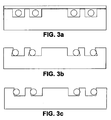
- Fig. 3a is a cross sectional side view of an optical fiber holder in accordance with the invention wherein side walls of the groove are orthogonal to the flat base of the groove and having a lid for containing the optical fiber within the grooved channel.
- Fig. 3b is a cross sectional side view of an optical fiber holder in accordance with the invention wherein outer side walls of the groove or channel form an acute angle with respect to the to the flat base of the groove.
- Fig. 3c is a cross sectional side view of an optical fiber holder in accordance with the invention wherein outer side walls of the groove first form an obtuse angle and subsequently form an acute angle with respect to the to the flat base of the groove providing a groove in the side wall in which the fiber is contained.
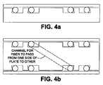
- Fig. 4a is a cross sectional side view of an optical fiber holder wherein the fiber diameter is greater than the channel depth and wherein a lid is provided to contact and contain the optical fiber and to provide heat sinking of heat within the optical fiber into the lid and channel walls.
- Fig. 4b is a cross sectional view of an optical fiber holder similar to Fig. 4a wherein both sides of the plate have a channel for holding the optical fiber and wherein the two channels have an internal groove or hole coupling them and for allowing an optical fiber to be wound on one side and to be threaded through to the other side for winding on the second side.
- an optical fiber holder 8 wherein a a side-loaded flat plate fixture 10 having a spiral channel 12 for holding a length of optical fiber 14 in a spiral pattern.
- the term "spiral" used within this specification is defined as curve on a plane that winds around a fixed center point at a continuously increasing or decreasing distance from the point.
- the optical fiber 14 can enter a channel 12 in the top of the plate 10 from the left side. It spirals around inwards at least once, but typically multiple times as shown in Fig. 1 , and ultimately exits from the inside of the spiral, where it is directed above or below the plane of the spiral in order to exit, which may be done, for example, by exiting the channel and passing through free space above the plate, or by entering a channel or hole that passes the fiber out toward the bottom side of the plate. In an alternative embodiment not shown the fiber can exit from an opening in the side of the plate just above or below the plane of the spiral.
- the optical fiber 14 disposed within the holder 8 is bidirectional and may be oriented in either possible direction, that is, the fiber can equally well enter the channel from the inside of the spiral and then it can spiral outwards. Since the fiber is essentially all held in one plane and the plate can be relatively thin, the entire structure can have a very low volume and can simply be incorporated into a laser or amplifier unit.
- the length of fiber that can be placed in one fixture is 19.1 meters. Such a length is well matched to the required lengths of optical fiber for typical fiber laser and amplifier applications.
- the plate can be manufactured in a straightforward manner out of many substances such as metal, ceramic, plastic, or composite.
- a metal such as aluminum is preferred since it has high thermal conductivity and can efficiently conduct heat away from the fiber.
- a ceramic such as aluminum nitride may also be a preferred material since it has not only fairly high thermal conductivity but also has a low coefficient of thermal expansion that is well matched to that of silica, which is typically the base material of optical fiber.
- Conventional fabrication processes can be utilized to machine the spiral channel into the plate.
- the surfaces of the channel and the plate should be very smooth and clean, In some embodiments it is also preferred the surfaces be substantially flat; the diameter of the fiber should be well controlled; and the optical fiber should preferably be coated with a compliant coating such as a polymer coating which will enable uniform contact with the fixture.
- a retaining plate 36 is attached to the top of the main plate 30 in order to ensure that the fiber does not accidentally come out of the channel 32.
- the plate 30 may be permanently affixed to the main plate 30 or preferably is removably coupled.
- the channel depth may be chosen so that the fiber protrudes slightly above the top surface of the main plate, so that the retaining plate physically contacts and squeezes the fiber, thus enabling improved heat sinking through both the bottom of the channel and the retaining plate. This is shown in Fig. 4a .
- the channel profile may be purposely shaped to retain the optical fiber placed within the channel.
- the inherent springiness of the fiber is exploited to allow the fiber to press itself against the outermost wall of the channel, which is slanted or otherwise incut in order to help prevent the fiber from accidentally moving or coming out of the channel during handling.
- the action of the fiber pressing itself against the outer wall of the channel improves the heat sinking of the fiber through the outer wall, and in the case of the first picture, the fiber is also being pressed against the bottom surface of the channel and will benefit from the added heat sinking in that direction as well.
- Fig. 3b shown an embodiment that is particularly convenient for housing an optical fiber and for providing adequate heat sinking via the side wall.
- the channel has a grooved side wall which substantially conforms to the shape of the fiber, thereby increasing the contact area of the side wall and the fiber.
- the side wall would have a shape that truly conformed to the optical fiber against it. For typical round fibers, this would be a semicircular outer side wall cross-sectional shape with radius approximately equal to the radius of the fiber so that the fiber can be snuggly housed.
- Fig 4a shows a preferred embodiment of the invention wherein a shaped channel 42a within the main plate 40a is combined with a retaining plate 48.
- a channel depth is shown that ensures that the optical fiber 44 protrudes above the top surface of the main plate 40a, so that the retaining plate 48a physically contacts and squeezes the optical fiber 44, thus enabling improved heat sinking through at least three surfaces: the bottom of the channel 42. the retaining plate 48a, and the outermost wall of the channel 42a.
- a main plate 40b is shown having spiral-shaped channels 42a and 42b on both sides.
- This device can hold twice as much optical fiber as a fixture with a channel on only one side shown in Fig. 4a .
- the optical fiber on one side of the fixture within channel 42a can be passed to the other side to the channel 42b through, for example, a channel 47 or hole through the plate, as shown, or by any other suitable path.
- a bottom retaining plate 48b is also provided.
- the channel is shaped to retain the fiber. This provides a significant advantage in terms of ease of use when loading the fiber into the fixture.
- the fiber in high-power fiber lasers is quite large and stiff, and it can spring out instantaneously during loading if there is no positive reinforcement that keeps it tightly in the channel.
- One aspect of this invention is using that stiffness of the fiber to ensure that it locks itself in place as it is loaded. The tight locking action is also valuable in ensuring good thermal contact and heat sinking, which is very important for high power fiber lasers.
Landscapes
- Physics & Mathematics (AREA)
- General Physics & Mathematics (AREA)
- Optics & Photonics (AREA)
- Optical Couplings Of Light Guides (AREA)
- Light Guides In General And Applications Therefor (AREA)
- Lasers (AREA)
Abstract
Description
- The present invention claims priority from United States Patent Application No.
60/908,245 filed March 27, 2007 - This invention relates generally to an optical fiber holding device and more particularly to a holding that facilitates heat sinking of excess heat within an optical fiber, into the holding device.
- Optical fiber is used as a transmission medium, both to transmit light from one point to another, as well as to modify the characteristics of light, for example as a gain medium in a fiber laser or an optical amplifier, or as a dispersion compensating medium in a telecommunications network. When an optical fiber is used to modify the characteristics of light rather than for transmission, it is often preferred that the optical fiber be contained in a relatively compact volume which will be incorporated inside an enclosed unit, typically with linear dimensions of less than 0.5 meter.
- Typical fiber-lasers or amplifier fibers are formed of lengths of optical fiber between 10 millimeters and 100 meters, most commonly in the 1-30 meter range, and generally the minimum permissible bend radius of the fibers is 10-20 millimeters. Other specialty optical fibers typically fall into the same range of parameters. Depending on the application, optical fibers may release enough heat, for example over one watt, to require efficient heat removal. Furthermore, the optical fibers used in fiber lasers should preferentially be protected from movement or accidental damage during handling. Due to the fragile nature of optical fiber, there is a need to protect the fiber from external sources of stress, such as bending, pressure and strain, which can damage the fiber and/or cause degradation of a signal being transmitted via the fiber. For example, a fiber should not be bent sharply anywhere along its path. In addition to the possibility of breakage or fracture, if a fiber is bent past a critical angle, portions of transmitted light pulses will leak out, rather than being reflected within the fiber core, thereby attenuating the transmitted light pulses and degrading signal quality. Accordingly, it is necessary that a fiber be routed so that bends in the fiber are of a sufficient radius to substantially avoid occurrence of such light leakage.
U.S. patent 6,980,726 in the name of Daoud et al ., discloses an optical fiber bend limiter that prevents contaminates from entering an optical fiber closure. - Compact lengths of optical fiber are traditionally held in spools similar to spools of string, that is, exteriorly-wound coils around a central spool or mandrel, with multiple coils, side-by-side, thus requiring a spool with significant thickness to accommodate the multiple coils; or lengths of optical fiber can be formed into loose coils bound to themselves with tape, plastic tie wraps, or similar devices. For example. United States Patent
6,738,554 in the name of Daoud et al ., entitled Double Helical-S Fiber Tray, discloses a tray in which optical fiber is wound in an "S" configuration. In this patent the optical fiber is shown to have lengths of optical fiber resting upon other lengths of optical fiber in layers building up within the enclosure. However, these known methods and devices for accommodating optical fiber do not necessarily ensure efficient heat removal or protection from movement or accidental damage, and they are often not as compact as desired. - There is therefore a need for a compact device for holding, protecting, and heat-sinking unwanted heat within a length of optical fiber.
- Heat build up and heat transfer within optical fibers becomes a particular concern in high power operation, for example at 100W or higher. In these instances lasing within the optical fiber at elevated temperatures inherently leads to losses in efficiency. This is a particular problem with Yb-doped fibers, because the energy levels are so close together in this dopant At elevated temperatures, the thermal population of the lower laser level is increased and the population of the upper state is decreased, leading to decreased inversion and efficiency. Hence, it is important to maintain the fiber core as close to room temperature as possible, and certainly under 70 degrees C. Another drawback to operating a fiber laser at elevated temperatures is that over time, fiber temperatures over the 70 C range can also degrade the polymer coatings on the fiber, and possibly the fiber core materials as well. In a fiber laser having hundreds of watts of output power, the fiber may be dissipating multiple watts of power per meter across a total surface area of typically only a few square centimeters per meter, so having minimal thermal resistance to a heat sink is imperative in order to keep the core temperature near room temperature. The fiber's cladding layers and polymer coatings have significant thermal resistance and can lead to a temperature rise of several degrees or tens of degrees C.
- Potting compound, and even "thermally conductive" potting compound, generally has much lower thermal conductivity than a metal; thus the use of any substantial thermal thickness of potting compound can significantly increase the thermal resistance and raise the core temperature. From the standpoint of contamination and optical damage, it is also important to minimize the amount of organic material in the vicinity of the fiber and particularly the fiber tips. The presence of the fiber polymer coating is is by design present and must be contended with, but potting material will typically be a much greater volume of organic material and much less cleanly applied. In the hot operating environment at full power, the use of potting compound raises a substantial risk of contamination of the fiber end faces with volatilized organic materials. Thus potting compound is not a desired solution to the problem of excess heat within the fiber.
- It is therefore an object of the invention to holding the fiber in a way that has excellent heat transfer directly into high-conductivity metal, and no added risk of contamination by organic materials.
- It is an object of this invention to provide a fiber holder that will hold a length of optical fiber in a compact manner while ensuring that the bend radius of the length of optical fiber is at least a predetermined radius so as to avoid the possibility of breakage, of excess tight leakage, and that will facilitate the heat sinking of heat from within the optical fiber to the holder.
- In accordance with the invention there is provided an optical fiber holding device having an optical fiber held therein comprising:
- base with a first spiral channel in an upper surface thereof holding and housing the optical fiber, the channel including:
- first opening in the side of the base for holding the first end of the optical fiber, plurality of turnings for holding the optical fiber wrapped therearound; center; and
- second opening in the center of the spiral for holding a second end of the optical fiber,
- In accordance with the invention there is provided, an optical fiber holding device comprising:
- base with a first spiral channel in an upper surface thereof for receiving an optical fiber, the channel including:
- first opening in the side of the base for receiving a first end of the optical fiber, plurality of turnings for receiving the optical fiber wrapped therearound; center; and
- second opening in the center of the spiral for receiving a second end of the optical fiber,
- In accordance with the invention there is provided, an optical fiber holding device comprising:
- base with a first spiral channel in an upper surface thereof for receiving an optical fiber, the channel including:
- first opening in the side of the base for receiving a first end of the optical fiber,
- plurality of turnings for receiving the optical fiber wrapped therearound; a center, and
- second opening in the center of the spiral for receiving a second end of the optical fiber,
- Exemplary embodiments of the invention will now be described in conjunction with the figures in which:
-
Fig. 1 is top view of a side loaded optical fiber holder in accordance with a first embodiment of this invention. -
Fig. 2 is a cross sectional side view of the optical fiber holder shown inFig. 1 . -
Fig. 3a is a cross sectional side view of an optical fiber holder in accordance with the invention wherein side walls of the groove are orthogonal to the flat base of the groove and having a lid for containing the optical fiber within the grooved channel. -
Fig. 3b is a cross sectional side view of an optical fiber holder in accordance with the invention wherein outer side walls of the groove or channel form an acute angle with respect to the to the flat base of the groove. -
Fig. 3c is a cross sectional side view of an optical fiber holder in accordance with the invention wherein outer side walls of the groove first form an obtuse angle and subsequently form an acute angle with respect to the to the flat base of the groove providing a groove in the side wall in which the fiber is contained. -
Fig. 4a is a cross sectional side view of an optical fiber holder wherein the fiber diameter is greater than the channel depth and wherein a lid is provided to contact and contain the optical fiber and to provide heat sinking of heat within the optical fiber into the lid and channel walls. -
Fig. 4b is a cross sectional view of an optical fiber holder similar toFig. 4a wherein both sides of the plate have a channel for holding the optical fiber and wherein the two channels have an internal groove or hole coupling them and for allowing an optical fiber to be wound on one side and to be threaded through to the other side for winding on the second side. - Referring now to
Fig. 1 and Fig. 2 , an optical fiber holder 8 is shown wherein a a side-loadedflat plate fixture 10 having a spiral channel 12 for holding a length of optical fiber 14 in a spiral pattern. The term "spiral" used within this specification is defined as curve on a plane that winds around a fixed center point at a continuously increasing or decreasing distance from the point. - As shown, the optical fiber 14 can enter a channel 12 in the top of the
plate 10 from the left side. It spirals around inwards at least once, but typically multiple times as shown inFig. 1 , and ultimately exits from the inside of the spiral, where it is directed above or below the plane of the spiral in order to exit, which may be done, for example, by exiting the channel and passing through free space above the plate, or by entering a channel or hole that passes the fiber out toward the bottom side of the plate. In an alternative embodiment not shown the fiber can exit from an opening in the side of the plate just above or below the plane of the spiral. Typically the optical fiber 14 disposed within the holder 8 is bidirectional and may be oriented in either possible direction, that is, the fiber can equally well enter the channel from the inside of the spiral and then it can spiral outwards. Since the fiber is essentially all held in one plane and the plate can be relatively thin, the entire structure can have a very low volume and can simply be incorporated into a laser or amplifier unit. - The length of an fiber in a simple near-circular spiral fixture with a given pitch between adjacent turns of the spiral, and minimum and maximum radii of the spiral given by r min and r max respectively, is given by the following formula:
-

- whereby it can be calculated that with typical possible values of r min = 30mm, r max = 100mm, and a pitch of 1.5mm, the length of fiber that can be placed in one fixture is 19.1 meters. Such a length is well matched to the required lengths of optical fiber for typical fiber laser and amplifier applications.
- The plate can be manufactured in a straightforward manner out of many substances such as metal, ceramic, plastic, or composite. A metal such as aluminum is preferred since it has high thermal conductivity and can efficiently conduct heat away from the fiber. A ceramic such as aluminum nitride may also be a preferred material since it has not only fairly high thermal conductivity but also has a low coefficient of thermal expansion that is well matched to that of silica, which is typically the base material of optical fiber. Conventional fabrication processes can be utilized to machine the spiral channel into the plate. For optimal heat sinking, it is preferred that the surfaces of the channel and the plate should be very smooth and clean, In some embodiments it is also preferred the surfaces be substantially flat; the diameter of the fiber should be well controlled; and the optical fiber should preferably be coated with a compliant coating such as a polymer coating which will enable uniform contact with the fixture.
- Several embodiments of the invention are illustrated in cross section in
Figs. 3a, 3b, and 3c . In the particular embodiment shown inFig. 3a , a retaining plate 36 is attached to the top of the main plate 30 in order to ensure that the fiber does not accidentally come out of the channel 32. The plate 30 may be permanently affixed to the main plate 30 or preferably is removably coupled. The channel depth may be chosen so that the fiber protrudes slightly above the top surface of the main plate, so that the retaining plate physically contacts and squeezes the fiber, thus enabling improved heat sinking through both the bottom of the channel and the retaining plate. This is shown inFig. 4a . - As is shown in
Figs. 3b and 3c the channel profile may be purposely shaped to retain the optical fiber placed within the channel. In these instances, the inherent springiness of the fiber is exploited to allow the fiber to press itself against the outermost wall of the channel, which is slanted or otherwise incut in order to help prevent the fiber from accidentally moving or coming out of the channel during handling. The action of the fiber pressing itself against the outer wall of the channel improves the heat sinking of the fiber through the outer wall, and in the case of the first picture, the fiber is also being pressed against the bottom surface of the channel and will benefit from the added heat sinking in that direction as well.Fig. 3b shown an embodiment that is particularly convenient for housing an optical fiber and for providing adequate heat sinking via the side wall. The channel has a grooved side wall which substantially conforms to the shape of the fiber, thereby increasing the contact area of the side wall and the fiber. Although it would likely increase cost of manufacturing, in a preferred embodiment the side wall would have a shape that truly conformed to the optical fiber against it. For typical round fibers, this would be a semicircular outer side wall cross-sectional shape with radius approximately equal to the radius of the fiber so that the fiber can be snuggly housed. -
Fig 4a shows a preferred embodiment of the invention wherein a shaped channel 42a within the main plate 40a is combined with a retaining plate 48. Here a channel depth is shown that ensures that the optical fiber 44 protrudes above the top surface of the main plate 40a, so that the retaining plate 48a physically contacts and squeezes the optical fiber 44, thus enabling improved heat sinking through at least three surfaces: the bottom of the channel 42. the retaining plate 48a, and the outermost wall of the channel 42a. - In
Fig. 4b a main plate 40b is shown having spiral-shaped channels 42a and 42b on both sides. This device can hold twice as much optical fiber as a fixture with a channel on only one side shown inFig. 4a . The optical fiber on one side of the fixture within channel 42a can be passed to the other side to the channel 42b through, for example, a channel 47 or hole through the plate, as shown, or by any other suitable path. Conveniently, a bottom retaining plate 48b is also provided. - As can be seen in
Figs. 3b, 3c .4a, and 4b . the channel is shaped to retain the fiber. This provides a significant advantage in terms of ease of use when loading the fiber into the fixture. The fiber in high-power fiber lasers is quite large and stiff, and it can spring out instantaneously during loading if there is no positive reinforcement that keeps it tightly in the channel. One aspect of this invention is using that stiffness of the fiber to ensure that it locks itself in place as it is loaded. The tight locking action is also valuable in ensuring good thermal contact and heat sinking, which is very important for high power fiber lasers.
Claims (23)
- An optical fiber holding device having an optical fiber held therein comprising:a base with a first spiral channel in an upper surface thereof holding and housing the optical fiber, the channel including:a first location where the fiber enters the channel;a plurality of turnings for holding the optical fiber wrapped there around; and,a second location where the fiber exits the channel wherein the bend radius of the optical fiber housed within the spiral channel is at least 2 cm.
- An optical fiber holding device as defined in claim 1 wherein the first location has a first opening is a side of the base for holding the first end of the optical fiber, and wherein the second location has a second opening in a centre of the spiral for holding a second end of the optical fiber.
- An optical fiber holding device as defined in claim 1, wherein the channel turnings have a cross section that is adapted to contain the optical fiber so that it does not spring out of the channel after it has been inserted.
- An optical fiber holding device as defined in claim 3, wherein the channel cross section has side walls that are at least partially inwardly slanted for retaining the optical fiber so that the optical fiber does not spring out of the channel after it has been inserted.
- An optical fiber holding device as defined in claim 3 wherein a cross section of the channel has a substantially flat bottom and upstanding side walls and wherein at least one upstanding side wall is slanted inward toward the other side wall for retaining the optical fiber so that the optical fiber does not spring out of the channel after it has been inserted.
- An optical fiber holding device as defined in claim 4 wherein the other side wall is not slanted and forms a right angle with respect to the flat bottom, and wherein the inward slanted sidewall is further from a centre of the spiral than the other sidewall adjacent thereto.
- An optical fiber holding device as defined in claim 2 wherein a cross section of the channel has a substantially flat bottom and upstanding side walls and wherein at least one upstanding side wall has an upper portion that is slanted inward toward the other side wall and forms an angle less than 90 degrees with the flat bottom for retaining the optical fiber so that the optical fiber does not spring out of the channel after it has been inserted.
- An optical fiber holding device as defined in claim 1, wherein the spiral channel forms an Archimedean spiral with an equal spacing between consecutive turnings.
- An optical fiber holding device as defined in claim 1, wherein the second opening extends at an acute angle to the base.
- An optical fiber holding device as defined in claim 1 further comprising a cover for covering the channel and containing the optical fiber within the base so that it does not spring out.
- An optical fiber holding device as defined in claim 9, wherein the diameter of the optical fiber is greater than a depth of the groove, so that the optical fiber makes contact with the cover when the cover is placed on the base, thereby allowing heat to dissipate from the fiber to the base and to the cover.
- An optical fiber holding device as defined in claim 1, having a second spiral channel in a lower surface of the base holding the optical fiber the second channel including:a first opening in the lower surface of the base for holding the optical fiber,a plurality of turnings for holding the optical fiber wrapped therearound;a center; anda second opening in the center of the spiral for holding a second end of the optical fiber.
- An optical fiber holding device as defined in claim 1, having a second spiral channel in a lower surface of the base holding a second different optical fiber the second channel including:a first opening in the lower surface of the base for holding the second different optical fiber,a plurality of turnings for holding the second different optical fiber wrapped therearound;a center: anda second opening in the center of the spiral for holding a second end of the second different optical fiber.
- An optical fiber holding device as defined in claim 11, further comprising first lid covering the upper surface of the base, and a second lid covering the lower surface of the base.
- An optical fiber holding device as defined in claim 12, further comprising first lid covering the upper surface of the base, and a second lid covering the lower surface of the base.
- An optical fiber holding device as defined in claim 1 wherein the base is a heat sinking material.
- An optical fiber holding device as defined in claim 3 wherein the base is a metal or metal composite for heat sinking unwanted heat within the optical fiber.
- The device according to claim 1, wherein a side wall of the channel includes a section at an acute angle to a base of the channel for frictionally engaging the optical fiber therebetween to increase thermal contact therebetween.
- The device according to claim 1, wherein outer inner side wall, furthest to the center, includes an angled sidewall for engaging the optical fiber, locking the optical fiber in place, and increasing thermal conductivity therebetween.
- The device according to claim 18, wherein the side wall also includes a section at an obtuse angle to the base of the channel for engaging the optical fiber to increase thermal contact.
- The device according to claim 1, wherein a side wall of the channel includes two sections with an obtuse angle therebetween to ensure the optical fiber contacts both sections.
- A side loaded flat plate having a spiral channel within a face thereof securely housing an optical fiber so that the optical fiber resides within the channel and makes contact to at least one sidewall of the channel.
- The device according to claim 1 wherein a cross section of an outer wall of the channel is semi-circular and sized to conform to and tightly accommodate the shape of the optical fiber.
Applications Claiming Priority (1)
| Application Number | Priority Date | Filing Date | Title |
|---|---|---|---|
| US90824507P | 2007-03-27 | 2007-03-27 |
Publications (3)
| Publication Number | Publication Date |
|---|---|
| EP1975660A2 true EP1975660A2 (en) | 2008-10-01 |
| EP1975660A3 EP1975660A3 (en) | 2008-12-10 |
| EP1975660B1 EP1975660B1 (en) | 2020-05-06 |
Family
ID=39561967
Family Applications (1)
| Application Number | Title | Priority Date | Filing Date |
|---|---|---|---|
| EP08250990.2A Active EP1975660B1 (en) | 2007-03-27 | 2008-03-20 | Optical fiber holder having a heat sink function |
Country Status (4)
| Country | Link |
|---|---|
| US (1) | US7809236B2 (en) |
| EP (1) | EP1975660B1 (en) |
| JP (1) | JP5442210B2 (en) |
| CN (1) | CN101276030A (en) |
Cited By (1)
| Publication number | Priority date | Publication date | Assignee | Title |
|---|---|---|---|---|
| US20120301097A1 (en) * | 2011-05-26 | 2012-11-29 | Omron Corporation | Fiber holder and fiber laser apparatus |
Families Citing this family (38)
| Publication number | Priority date | Publication date | Assignee | Title |
|---|---|---|---|---|
| EP2043204B1 (en) * | 2006-07-19 | 2016-05-04 | Nikon Corporation | Cassette for optical fiber amplifier, optical fiber amplifier and light source device |
| JP5366488B2 (en) * | 2008-09-26 | 2013-12-11 | 株式会社フジクラ | Optical fiber reel and optical device |
| US8594478B2 (en) * | 2009-03-20 | 2013-11-26 | Patient Pocket, Llc | Method and apparatus for storing a laser optical fiber |
| US8340482B2 (en) * | 2009-03-31 | 2012-12-25 | Furukawa Electric Co., Ltd. | Optical fiber holding apparatus |
| JP5367446B2 (en) * | 2009-05-01 | 2013-12-11 | 古河電気工業株式会社 | Optical amplification device and optical transmission system |
| US8346043B2 (en) * | 2009-07-30 | 2013-01-01 | Jds Uniphase Corporation | Fiber tray |
| JP5753718B2 (en) * | 2011-03-31 | 2015-07-22 | 株式会社フジクラ | Optical delivery component and laser device using the same |
| US8737437B2 (en) * | 2012-03-05 | 2014-05-27 | Ofs Fitel, Llc | Fiber laser cavity optical engine package and method of making the same |
| CN103376522A (en) * | 2012-04-27 | 2013-10-30 | 上海科乃特激光科技有限公司 | Winding device for active optical fiber |
| CN102751647A (en) * | 2012-06-15 | 2012-10-24 | 北京国科世纪激光技术有限公司 | Optical fiber coiling device |
| JP6034708B2 (en) * | 2013-01-30 | 2016-11-30 | 株式会社フジクラ | Optical amplification component and fiber laser device |
| US20140362876A1 (en) * | 2013-06-06 | 2014-12-11 | Prima Electro North America, LLC | Method and system for managing heat disipation in doped fiber |
| JP6113630B2 (en) * | 2013-11-06 | 2017-04-12 | 株式会社フジクラ | Optical amplification component and fiber laser device |
| US9214781B2 (en) | 2013-11-21 | 2015-12-15 | Lockheed Martin Corporation | Fiber amplifier system for suppression of modal instabilities and method |
| CN104659639A (en) * | 2013-11-21 | 2015-05-27 | 上海瀚宇光纤通信技术有限公司 | High-power optical fiber amplifier with high heat dissipation rate |
| JP6301959B2 (en) * | 2013-12-11 | 2018-03-28 | 古河電気工業株式会社 | Laser apparatus and optical fiber laser |
| CN103825165A (en) * | 2013-12-26 | 2014-05-28 | 北京航天时代光电科技有限公司 | High-power all-fiber laser with circular structure |
| CN103746275A (en) * | 2014-01-26 | 2014-04-23 | 江苏天元激光科技有限公司 | Active optical fiber winding device and optical fiber winding method for optical fiber laser |
| US9753232B2 (en) * | 2014-03-21 | 2017-09-05 | Corning Optical Communications LLC | Fiber organizer for retaining and routing optical fibers within fiber optic plug connectors, and related devices, components, and methods |
| JP6565374B2 (en) * | 2015-06-26 | 2019-08-28 | 三星ダイヤモンド工業株式会社 | Fiber optic equipment |
| CN105337147B (en) * | 2015-11-30 | 2016-11-16 | 深圳市创鑫激光股份有限公司 | A kind of optical fiber laser |
| CN105502098A (en) * | 2016-01-14 | 2016-04-20 | 武汉锐科光纤激光技术股份有限公司 | Optical fiber coiling tool |
| US11025034B2 (en) | 2016-08-31 | 2021-06-01 | Nlight, Inc. | Laser cooling system |
| WO2018112220A1 (en) * | 2016-12-15 | 2018-06-21 | Nlight, Inc. | Fiber laser packaging |
| CN106711746B (en) * | 2017-01-09 | 2023-04-18 | 山东海富光子科技股份有限公司 | Optical fiber coiling device applied to high-power optical fiber laser |
| US10288802B2 (en) * | 2017-05-02 | 2019-05-14 | Teraxion | Optical fiber heat dissipation package |
| CN107161803A (en) * | 2017-06-30 | 2017-09-15 | 华中科技大学鄂州工业技术研究院 | A kind of multifunctional optical fiber coiling apparatus |
| CN112119546B (en) * | 2018-03-12 | 2024-03-26 | 恩耐公司 | Fiber laser with variable coiled fiber |
| IL260758B (en) * | 2018-07-24 | 2020-01-30 | Elbit Systems Electro Optics Elop Ltd | Array for storing optical fibers |
| CN109103735A (en) * | 2018-09-28 | 2018-12-28 | 深圳市杰普特光电股份有限公司 | CW Fiber Laser Module |
| JP6695039B2 (en) * | 2019-04-15 | 2020-05-20 | 三星ダイヤモンド工業株式会社 | Fiber optic equipment |
| CN112002226B (en) | 2020-08-17 | 2022-02-22 | 武汉华星光电半导体显示技术有限公司 | Flexible display device |
| CN112859275B (en) * | 2021-01-20 | 2021-12-14 | 中国科学院西安光学精密机械研究所 | Cold optics self-adaptation thermal deformation compensation structure based on Archimedes spiral |
| CN113654767A (en) * | 2021-08-27 | 2021-11-16 | 武汉睿芯特种光纤有限责任公司 | Coiling tool for optical fiber testing |
| CN114200611B (en) * | 2021-12-23 | 2023-06-09 | 上海海洋大学 | Tangle-Resistant Fiber Optic Components |
| JP2023121215A (en) * | 2022-02-21 | 2023-08-31 | 株式会社フジクラ | Fiber laser device |
| FR3135032B1 (en) * | 2022-04-29 | 2024-09-20 | Faurecia Sieges Dautomobile | Seat upholstery element comprising a backlit pattern area |
| IL298391B2 (en) * | 2022-11-13 | 2024-10-01 | Elbit Systems Electro Optics Elop Ltd | Device, system and method for compact packaging for an active fiber of a fiber laser |
Citations (2)
| Publication number | Priority date | Publication date | Assignee | Title |
|---|---|---|---|---|
| US6738554B2 (en) | 2001-05-07 | 2004-05-18 | Lucent Technologies Inc. | Double helical-S fiber tray |
| US6980726B2 (en) | 2003-05-30 | 2005-12-27 | Lucent Technologies Inc. | Fiber bend limiting device with a dust sealing feature |
Family Cites Families (8)
| Publication number | Priority date | Publication date | Assignee | Title |
|---|---|---|---|---|
| DE3532314A1 (en) * | 1985-09-11 | 1987-03-12 | Philips Patentverwaltung | RECEIVING DEVICE FOR A STOCK LENGTH OF AN OPTICAL PIPE |
| JPH0637806U (en) * | 1992-10-27 | 1994-05-20 | 古河電気工業株式会社 | Optical fiber extra length storage |
| US5359687A (en) * | 1993-08-23 | 1994-10-25 | Alliedsignal Inc. | Polymer microstructures which facilitate fiber optic to waveguide coupling |
| US5659647A (en) * | 1995-10-30 | 1997-08-19 | Sandia Corporation | Fiber alignment apparatus and method |
| US6174648B1 (en) | 1997-07-08 | 2001-01-16 | Oki Electric Industry Co., Ltd. | Optical filter fabrication method using fiber holder with spiral groove and phase mask with spiral diffraction grating |
| JP3421218B2 (en) * | 1997-07-08 | 2003-06-30 | 沖電気工業株式会社 | Method for manufacturing optical filter, support member, and phase mask |
| ATE262229T1 (en) * | 1998-12-15 | 2004-04-15 | Contraves Space Ag | POWER AMPLIFIER FOR AMPLIFYING LASER RADIATION, METHOD FOR PRODUCING AND USING THE POWER AMPLIFIER |
| JP2001274489A (en) * | 2000-03-27 | 2001-10-05 | Toshiba Corp | Optical fiber heat dissipation device |
-
2008
- 2008-03-19 US US12/051,189 patent/US7809236B2/en active Active
- 2008-03-20 EP EP08250990.2A patent/EP1975660B1/en active Active
- 2008-03-26 JP JP2008080845A patent/JP5442210B2/en active Active
- 2008-03-27 CN CNA2008100842502A patent/CN101276030A/en active Pending
Patent Citations (2)
| Publication number | Priority date | Publication date | Assignee | Title |
|---|---|---|---|---|
| US6738554B2 (en) | 2001-05-07 | 2004-05-18 | Lucent Technologies Inc. | Double helical-S fiber tray |
| US6980726B2 (en) | 2003-05-30 | 2005-12-27 | Lucent Technologies Inc. | Fiber bend limiting device with a dust sealing feature |
Cited By (2)
| Publication number | Priority date | Publication date | Assignee | Title |
|---|---|---|---|---|
| US20120301097A1 (en) * | 2011-05-26 | 2012-11-29 | Omron Corporation | Fiber holder and fiber laser apparatus |
| US8837895B2 (en) * | 2011-05-26 | 2014-09-16 | Omron Corporation | Fiber holder and fiber laser apparatus |
Also Published As
| Publication number | Publication date |
|---|---|
| CN101276030A (en) | 2008-10-01 |
| JP2008244483A (en) | 2008-10-09 |
| JP5442210B2 (en) | 2014-03-12 |
| US7809236B2 (en) | 2010-10-05 |
| EP1975660B1 (en) | 2020-05-06 |
| EP1975660A3 (en) | 2008-12-10 |
| US20090060444A1 (en) | 2009-03-05 |
Similar Documents
| Publication | Publication Date | Title |
|---|---|---|
| US7809236B2 (en) | Optical fiber holder and heat sink | |
| US6424784B1 (en) | Grating coil package for reduced fiber strain | |
| US7957623B2 (en) | Deformable thermal pads for optical fibers | |
| US8493651B1 (en) | Apparatus for optical fiber management and cooling | |
| CA2728796C (en) | Energy dissipating packages for high power operation of optical fiber components | |
| US5930430A (en) | Integrated laser diode and fiber grating assembly | |
| EP2076806B1 (en) | Optical fiber module | |
| US8885993B2 (en) | Dual-index optical pump stripper assembly | |
| US6546179B2 (en) | Guide for routing cables through panel openings | |
| US7000863B2 (en) | Method and apparatus for operational low-stress optical fiber storage | |
| JP2994623B2 (en) | Optical fiber amplifier packaging equipment | |
| EP3082205B1 (en) | Laser device and optical fiber laser | |
| JP5100693B2 (en) | Optical fiber holding structure | |
| WO2012148682A1 (en) | Temperature control of a fiber laser system | |
| JP7228669B2 (en) | Active fiber package | |
| US10749309B2 (en) | Compact optical fiber amplifier | |
| CA2810351C (en) | Dual-index optical pump stripper assembly | |
| CN115933078B (en) | Optical fiber coiling device | |
| US11280973B2 (en) | Compact package for high-aspect-ratio rectangular (HARR) optical fiber or other optical fiber | |
| JP2010191085A (en) | Spacer for optical fiber cable and optical fiber cable having the same | |
| JP3436875B2 (en) | Extra storage tray | |
| EP1272880B1 (en) | Grating coil package for reduced fiber strain | |
| JP6586194B2 (en) | Compact optical fiber amplifier | |
| JP2018508996A (en) | Compact optical fiber amplifier | |
| US9865981B2 (en) | Fiber laser packaging |
Legal Events
| Date | Code | Title | Description |
|---|---|---|---|
| PUAI | Public reference made under article 153(3) epc to a published international application that has entered the european phase |
Free format text: ORIGINAL CODE: 0009012 |
|
| AK | Designated contracting states |
Kind code of ref document: A2 Designated state(s): AT BE BG CH CY CZ DE DK EE ES FI FR GB GR HR HU IE IS IT LI LT LU LV MC MT NL NO PL PT RO SE SI SK TR |
|
| AX | Request for extension of the european patent |
Extension state: AL BA MK RS |
|
| PUAL | Search report despatched |
Free format text: ORIGINAL CODE: 0009013 |
|
| AK | Designated contracting states |
Kind code of ref document: A3 Designated state(s): AT BE BG CH CY CZ DE DK EE ES FI FR GB GR HR HU IE IS IT LI LT LU LV MC MT NL NO PL PT RO SE SI SK TR |
|
| AX | Request for extension of the european patent |
Extension state: AL BA MK RS |
|
| 17P | Request for examination filed |
Effective date: 20090422 |
|
| 17Q | First examination report despatched |
Effective date: 20090520 |
|
| AKX | Designation fees paid |
Designated state(s): DE GB |
|
| RAP1 | Party data changed (applicant data changed or rights of an application transferred) |
Owner name: LUMENTUM OPERATIONS LLC |
|
| GRAP | Despatch of communication of intention to grant a patent |
Free format text: ORIGINAL CODE: EPIDOSNIGR1 |
|
| INTG | Intention to grant announced |
Effective date: 20160428 |
|
| GRAJ | Information related to disapproval of communication of intention to grant by the applicant or resumption of examination proceedings by the epo deleted |
Free format text: ORIGINAL CODE: EPIDOSDIGR1 |
|
| INTC | Intention to grant announced (deleted) | ||
| STAA | Information on the status of an ep patent application or granted ep patent |
Free format text: STATUS: EXAMINATION IS IN PROGRESS |
|
| GRAP | Despatch of communication of intention to grant a patent |
Free format text: ORIGINAL CODE: EPIDOSNIGR1 |
|
| STAA | Information on the status of an ep patent application or granted ep patent |
Free format text: STATUS: GRANT OF PATENT IS INTENDED |
|
| INTG | Intention to grant announced |
Effective date: 20191023 |
|
| GRAS | Grant fee paid |
Free format text: ORIGINAL CODE: EPIDOSNIGR3 |
|
| GRAA | (expected) grant |
Free format text: ORIGINAL CODE: 0009210 |
|
| STAA | Information on the status of an ep patent application or granted ep patent |
Free format text: STATUS: THE PATENT HAS BEEN GRANTED |
|
| AK | Designated contracting states |
Kind code of ref document: B1 Designated state(s): DE GB |
|
| REG | Reference to a national code |
Ref country code: GB Ref legal event code: FG4D |
|
| REG | Reference to a national code |
Ref country code: DE Ref legal event code: R096 Ref document number: 602008062636 Country of ref document: DE |
|
| REG | Reference to a national code |
Ref country code: DE Ref legal event code: R097 Ref document number: 602008062636 Country of ref document: DE |
|
| PLBE | No opposition filed within time limit |
Free format text: ORIGINAL CODE: 0009261 |
|
| STAA | Information on the status of an ep patent application or granted ep patent |
Free format text: STATUS: NO OPPOSITION FILED WITHIN TIME LIMIT |
|
| 26N | No opposition filed |
Effective date: 20210209 |
|
| GBPC | Gb: european patent ceased through non-payment of renewal fee |
Effective date: 20210320 |
|
| PG25 | Lapsed in a contracting state [announced via postgrant information from national office to epo] |
Ref country code: GB Free format text: LAPSE BECAUSE OF NON-PAYMENT OF DUE FEES Effective date: 20210320 |
|
| PGFP | Annual fee paid to national office [announced via postgrant information from national office to epo] |
Ref country code: DE Payment date: 20250331 Year of fee payment: 18 |