JP5753718B2 - Optical delivery component and laser device using the same - Google Patents
Optical delivery component and laser device using the same Download PDFInfo
- Publication number
- JP5753718B2 JP5753718B2 JP2011081108A JP2011081108A JP5753718B2 JP 5753718 B2 JP5753718 B2 JP 5753718B2 JP 2011081108 A JP2011081108 A JP 2011081108A JP 2011081108 A JP2011081108 A JP 2011081108A JP 5753718 B2 JP5753718 B2 JP 5753718B2
- Authority
- JP
- Japan
- Prior art keywords
- light
- fiber
- light emitting
- delivery
- cladding
- Prior art date
- Legal status (The legal status is an assumption and is not a legal conclusion. Google has not performed a legal analysis and makes no representation as to the accuracy of the status listed.)
- Expired - Fee Related
Links
Images


Classifications
-
- H—ELECTRICITY
- H01—ELECTRIC ELEMENTS
- H01S—DEVICES USING THE PROCESS OF LIGHT AMPLIFICATION BY STIMULATED EMISSION OF RADIATION [LASER] TO AMPLIFY OR GENERATE LIGHT; DEVICES USING STIMULATED EMISSION OF ELECTROMAGNETIC RADIATION IN WAVE RANGES OTHER THAN OPTICAL
- H01S3/00—Lasers, i.e. devices using stimulated emission of electromagnetic radiation in the infrared, visible or ultraviolet wave range
- H01S3/05—Construction or shape of optical resonators; Accommodation of active medium therein; Shape of active medium
- H01S3/06—Construction or shape of active medium
- H01S3/063—Waveguide lasers, i.e. whereby the dimensions of the waveguide are of the order of the light wavelength
- H01S3/067—Fibre lasers
- H01S3/06754—Fibre amplifiers
-
- H—ELECTRICITY
- H01—ELECTRIC ELEMENTS
- H01S—DEVICES USING THE PROCESS OF LIGHT AMPLIFICATION BY STIMULATED EMISSION OF RADIATION [LASER] TO AMPLIFY OR GENERATE LIGHT; DEVICES USING STIMULATED EMISSION OF ELECTROMAGNETIC RADIATION IN WAVE RANGES OTHER THAN OPTICAL
- H01S3/00—Lasers, i.e. devices using stimulated emission of electromagnetic radiation in the infrared, visible or ultraviolet wave range
- H01S3/05—Construction or shape of optical resonators; Accommodation of active medium therein; Shape of active medium
- H01S3/06—Construction or shape of active medium
- H01S3/063—Waveguide lasers, i.e. whereby the dimensions of the waveguide are of the order of the light wavelength
- H01S3/067—Fibre lasers
- H01S3/06704—Housings; Packages
-
- G—PHYSICS
- G02—OPTICS
- G02B—OPTICAL ELEMENTS, SYSTEMS OR APPARATUS
- G02B6/00—Light guides; Structural details of arrangements comprising light guides and other optical elements, e.g. couplings
- G02B6/24—Coupling light guides
- G02B6/26—Optical coupling means
- G02B6/28—Optical coupling means having data bus means, i.e. plural waveguides interconnected and providing an inherently bidirectional system by mixing and splitting signals
- G02B6/2804—Optical coupling means having data bus means, i.e. plural waveguides interconnected and providing an inherently bidirectional system by mixing and splitting signals forming multipart couplers without wavelength selective elements, e.g. "T" couplers, star couplers
-
- H—ELECTRICITY
- H01—ELECTRIC ELEMENTS
- H01S—DEVICES USING THE PROCESS OF LIGHT AMPLIFICATION BY STIMULATED EMISSION OF RADIATION [LASER] TO AMPLIFY OR GENERATE LIGHT; DEVICES USING STIMULATED EMISSION OF ELECTROMAGNETIC RADIATION IN WAVE RANGES OTHER THAN OPTICAL
- H01S3/00—Lasers, i.e. devices using stimulated emission of electromagnetic radiation in the infrared, visible or ultraviolet wave range
- H01S3/02—Constructional details
- H01S3/04—Arrangements for thermal management
- H01S3/0405—Conductive cooling, e.g. by heat sinks or thermo-electric elements
-
- H—ELECTRICITY
- H01—ELECTRIC ELEMENTS
- H01S—DEVICES USING THE PROCESS OF LIGHT AMPLIFICATION BY STIMULATED EMISSION OF RADIATION [LASER] TO AMPLIFY OR GENERATE LIGHT; DEVICES USING STIMULATED EMISSION OF ELECTROMAGNETIC RADIATION IN WAVE RANGES OTHER THAN OPTICAL
- H01S3/00—Lasers, i.e. devices using stimulated emission of electromagnetic radiation in the infrared, visible or ultraviolet wave range
- H01S3/05—Construction or shape of optical resonators; Accommodation of active medium therein; Shape of active medium
- H01S3/06—Construction or shape of active medium
- H01S3/063—Waveguide lasers, i.e. whereby the dimensions of the waveguide are of the order of the light wavelength
- H01S3/067—Fibre lasers
- H01S3/0675—Resonators including a grating structure, e.g. distributed Bragg reflectors [DBR] or distributed feedback [DFB] fibre lasers
-
- H—ELECTRICITY
- H01—ELECTRIC ELEMENTS
- H01S—DEVICES USING THE PROCESS OF LIGHT AMPLIFICATION BY STIMULATED EMISSION OF RADIATION [LASER] TO AMPLIFY OR GENERATE LIGHT; DEVICES USING STIMULATED EMISSION OF ELECTROMAGNETIC RADIATION IN WAVE RANGES OTHER THAN OPTICAL
- H01S3/00—Lasers, i.e. devices using stimulated emission of electromagnetic radiation in the infrared, visible or ultraviolet wave range
- H01S3/09—Processes or apparatus for excitation, e.g. pumping
- H01S3/091—Processes or apparatus for excitation, e.g. pumping using optical pumping
- H01S3/094—Processes or apparatus for excitation, e.g. pumping using optical pumping by coherent light
- H01S3/094003—Processes or apparatus for excitation, e.g. pumping using optical pumping by coherent light the pumped medium being a fibre
- H01S3/094011—Processes or apparatus for excitation, e.g. pumping using optical pumping by coherent light the pumped medium being a fibre with bidirectional pumping, i.e. with injection of the pump light from both two ends of the fibre
-
- H—ELECTRICITY
- H01—ELECTRIC ELEMENTS
- H01S—DEVICES USING THE PROCESS OF LIGHT AMPLIFICATION BY STIMULATED EMISSION OF RADIATION [LASER] TO AMPLIFY OR GENERATE LIGHT; DEVICES USING STIMULATED EMISSION OF ELECTROMAGNETIC RADIATION IN WAVE RANGES OTHER THAN OPTICAL
- H01S3/00—Lasers, i.e. devices using stimulated emission of electromagnetic radiation in the infrared, visible or ultraviolet wave range
- H01S3/09—Processes or apparatus for excitation, e.g. pumping
- H01S3/091—Processes or apparatus for excitation, e.g. pumping using optical pumping
- H01S3/094—Processes or apparatus for excitation, e.g. pumping using optical pumping by coherent light
- H01S3/0941—Processes or apparatus for excitation, e.g. pumping using optical pumping by coherent light of a laser diode
- H01S3/09415—Processes or apparatus for excitation, e.g. pumping using optical pumping by coherent light of a laser diode the pumping beam being parallel to the lasing mode of the pumped medium, e.g. end-pumping
Description
本発明は、熱による損傷を防止することができる光デリバリ部品、及び、それを用いたレーザ装置に関する。 The present invention relates to an optical delivery component capable of preventing damage due to heat, and a laser apparatus using the same.
ファイバレーザ装置は、加工機、医療機器、測定器の分野等において用いられ、増幅用光ファイバにおいて増幅された光が出力されるものである。このようなファイバレーザ装置においては、ダブルクラッドファイバから成る増幅用光ファイバにおいて増幅される信号光が、増幅用光ファイバのコアから出力され、増幅用光ファイバに接続されたシングルクラッドファイバから成るデリバリファイバのコアに入力されて、デリバリファイバにより所望の場所まで伝播されてから、出力される場合がある。 The fiber laser device is used in the fields of processing machines, medical devices, measuring instruments, and the like, and outputs light amplified in an amplification optical fiber. In such a fiber laser device, signal light amplified in an amplification optical fiber composed of a double clad fiber is output from the core of the amplification optical fiber and is delivered from a single clad fiber connected to the amplification optical fiber. In some cases, the signal is input to the core of the fiber, propagated to a desired location by the delivery fiber, and then output.
しかし、増幅用光ファイバから出力される光としては、コアから出力される信号光の他に、クラッドから出力される余剰励起光があり、上述のように増幅用光ファイバにデリバリファイバが接続されている場合、この余剰励起光は、デリバリファイバのクラッドに入力する。また、増幅用光ファイバのコアを伝播する信号光と、デリバリファイバのコアを伝播する信号光とのモードフィールド径の不一致や、増幅用光ファイバとデリバリファイバとの接続における軸ずれ、角度ずれ等により、増幅用光ファイバから出力される信号光の一部が、デリバリファイバのクラッドに入力する場合がある。 However, as the light output from the amplification optical fiber, in addition to the signal light output from the core, there is surplus excitation light output from the cladding, and the delivery fiber is connected to the amplification optical fiber as described above. If this is the case, this excess excitation light is input to the cladding of the delivery fiber. Also, mismatch in mode field diameter between the signal light propagating through the core of the amplification optical fiber and the signal light propagating through the core of the delivery fiber, axial misalignment, angular misalignment, etc. in the connection between the amplification optical fiber and the delivery fiber Thus, part of the signal light output from the amplification optical fiber may be input to the cladding of the delivery fiber.
デリバリファイバのクラッドに入力するこれらの光は、デリバリファイバの被覆層に吸収されて、被覆層が焼損するといった問題が生じることがある。従って、デリバリファイバのクラッドに入力する光は、適切に放出されることが望ましい。 Such light that enters the cladding of the delivery fiber may be absorbed by the coating layer of the delivery fiber, causing a problem that the coating layer burns out. Therefore, it is desirable that the light input to the cladding of the delivery fiber is emitted appropriately.
下記特許文献1には、このようなクラッドに入力した光を放出する光ファイバの融着接続構造が記載されている。この融着接続構造においては、ダブルクラッドファイバとシングルクラッドファイバとが直線状に並べられて接続され、少なくともシングルクラッドファイバの融着点付近が高熱伝導性のブロックで覆われている。従って、ダブルクラッドファイバからシングルクラッドファイバのクラッドに光が入力し、この光の放射により、熱が発生する場合においても、この熱がブロックに吸収され、光ファイバの被覆の劣化を防止することができるとされている。 Japanese Patent Application Laid-Open No. H10-228707 describes an optical fiber fusion splicing structure that emits light input to the cladding. In this fusion spliced structure, the double clad fiber and the single clad fiber are arranged in a straight line and connected, and at least the vicinity of the fusion point of the single clad fiber is covered with a high thermal conductivity block. Therefore, even when light is input from the double-clad fiber to the clad of the single-clad fiber and heat is generated by the radiation of this light, this heat is absorbed by the block, preventing deterioration of the coating of the optical fiber. It is supposed to be possible.
また、下記特許文献2には、クラッドに入力した光を放出するレーザ伝達装置が記載されている。このレーザ伝達装置においては、光ファイバのクラッドが一部露出された部分が、所定の曲率で曲げられると共に、光透過部材で覆われ、さらに光透過部材に光吸収部材・冷却部材が設けられるというものである。この様な構成により、クラッドが露出した部分において、クラッドを伝播する光を略完全に除去できるとされている。
上述のように増幅用光ファイバからデリバリファイバに入力する光には、増幅用光ファイバのクラッドを伝播する励起光と、コアを伝播する信号光とがある。一般に励起光は、NA(開口数:Numerical Aperture)が大きい成分が多い光であり、信号光は、励起光と比べるとNAの比較的小さい成分が多い光である。そして、NAの小さい成分は、NAの大きい成分よりも直進性が良い。 As described above, light input from the amplification optical fiber to the delivery fiber includes excitation light that propagates through the cladding of the amplification optical fiber and signal light that propagates through the core. In general, excitation light is light having many components with a large NA (Numerical Aperture), and signal light is light having many components having a relatively small NA as compared with excitation light. A component having a small NA has better straightness than a component having a large NA.
従って、特許文献1に記載の光ファイバの融着接続構造によれば、光ファイバが直線上に並べられているため、NAの小さい成分は、高熱伝導性のブロックで覆われている部分において放出されづらい。従って、高熱伝導性のブロックで覆われていない部分において、光ファイバが曲げられると、この部分でNAの小さい成分がクラッドから放出されて被覆層を損傷する虞がある。一方、特許文献2に記載のレーザ伝達装置においては、光ファイバが曲げられている部分において、光のNAの小さい成分とNAの大きい成分とが、一気に放出されて熱に変換されるため、発熱する場所が集中して、冷却部材が設けられる場合においても、光ファイバが熱により損傷する虞がある。
Therefore, according to the fusion splicing structure of the optical fiber described in Patent Document 1, since the optical fibers are arranged in a straight line, a component with a small NA is emitted in the portion covered with the high thermal conductivity block. Hard to be done. Therefore, if the optical fiber is bent in a portion not covered with the high thermal conductivity block, a component having a small NA may be emitted from the clad in this portion and damage the coating layer. On the other hand, in the laser transmission device described in
そこで、本発明は、熱による損傷を防止することができる光デリバリ部品、及び、それを用いたレーザ装置を提供することを目的とする。 Accordingly, an object of the present invention is to provide an optical delivery component capable of preventing damage due to heat, and a laser device using the same.
本発明の光デリバリ部品は、コア及びクラッドを有するデリバリファイバと、放熱部材と、を備え、前記デリバリファイバは、前記放熱部材の一部に接続される第1光放出部と、前記放熱部材の他の一部に接続される第2光放出部とを有すると共に、少なくとも第2光放出部が曲げられており、前記第1光放出部は、前記第2光放出部よりもデリバリファイバにおける光の入力端側に設けられると共に、前記第2光放出部よりも曲げ半径が大きくされることを特徴とするものである。 An optical delivery component of the present invention includes a delivery fiber having a core and a clad, and a heat dissipation member, and the delivery fiber includes a first light emitting unit connected to a part of the heat dissipation member, and the heat dissipation member. A second light emitting portion connected to another part, and at least the second light emitting portion is bent, and the first light emitting portion is light in the delivery fiber more than the second light emitting portion. Is provided on the input end side, and has a bending radius larger than that of the second light emitting portion.
このような光デリバリ部品においては、デリバリファイバのクラッドにNAの小さな光とNAの大きな光とを有する光が入力すると、この光は、第1光放出部、第2放熱部の順に伝播する。NAの大きな光は、デリバリファイバのクラッドの外周面に対する入射角が小さく、クラッドから放出され易い。一方、NAの小さな光は、デリバリファイバのクラッドの外周面に対する入射角が大きく、クラッドから放出されづらい。従って、第1光放出部は、第2放熱部よりも曲げ半径が大きくされるため、クラッドに入力した光の内、比較的NAの大きな光が第1放出部から放出される。そして、第2光放出部は、第1光放出部よりも曲げ半径が小さいため、比較的NAの大きな光も比較的NAの小さな光も放出することができる。従って、第2光放出部においては、第1光放出部を通過した残りの光が放出される。そして、第1光放出部から放出される光により発生する熱は、放熱部材の一部から放熱され、第2光放出部から放出される光により発生する熱は、放熱部材の他の一部から放熱される。このようにNAの比較的大きな光と、NAの比較的小さな光を含む光とを異なる場所で放出して、それぞれ発熱させることにより、発熱する場所が集中することを防止でき、分散して発熱した熱をそれぞれ適切に放出することができる。従って、熱による損傷を防止することができる。 In such an optical delivery component, when light having a small NA and a large NA is input to the cladding of the delivery fiber, this light propagates in the order of the first light emitting portion and the second heat radiating portion. Light having a large NA has a small incident angle with respect to the outer peripheral surface of the cladding of the delivery fiber, and is easily emitted from the cladding. On the other hand, light having a small NA has a large incident angle with respect to the outer peripheral surface of the cladding of the delivery fiber and is not easily emitted from the cladding. Accordingly, since the first light emitting portion has a larger bending radius than the second heat radiating portion, light having a relatively large NA among the light input to the cladding is emitted from the first emitting portion. Since the second light emitting portion has a smaller bending radius than the first light emitting portion, both the light having a relatively large NA and the light having a relatively small NA can be emitted. Therefore, the remaining light that has passed through the first light emitting portion is emitted from the second light emitting portion. The heat generated by the light emitted from the first light emitting part is radiated from a part of the heat radiating member, and the heat generated by the light emitted from the second light emitting part is the other part of the radiating member. Radiated from the heat. In this way, by emitting light having a relatively large NA and light including light having a relatively small NA at different places and generating heat, it is possible to prevent the places where the heat is generated from concentrating and to generate heat by dispersion. Can be released appropriately. Therefore, damage due to heat can be prevented.
また、前記第1光放出部は、直線状とされることが好ましい。 The first light emitting part is preferably linear.
第1光放出部を直線上とすることにより、NAの小さな光を適切に第2光放出部まで伝播させることができ、第1光放出部及び第2光放出部において、より適切に発生する熱を分散することができる。 By setting the first light emitting portion on a straight line, light having a small NA can be appropriately propagated to the second light emitting portion, and more appropriately generated in the first light emitting portion and the second light emitting portion. Heat can be dispersed.
また、上記の様に前記第1光放出部が、直線状とされる場合においては、前記第2光放出部は、一定の曲げ半径とされることとしても良い。 In addition, when the first light emitting portion is linear as described above, the second light emitting portion may have a constant bending radius.
このような構成にすることにより、放熱部材における第2光放出部が接続される部分の形成が容易になる。例えば、放熱部材は、通常熱伝導の良いアルミ等をフライス盤等の金属加工機で加工して作成するが、第2放出部が一定の曲げ半径とされることにより、放熱部材における第2光放出部が接続される部分を一定の曲げ半径で加工することができ、加工が容易になる。従って、放熱部材を安価に抑えることが可能になる。とすることができる。 With such a configuration, it is easy to form a portion of the heat dissipation member to which the second light emitting portion is connected. For example, the heat dissipating member is usually made by processing aluminum or the like having good heat conductivity with a metal working machine such as a milling machine, but the second light emitting part of the heat dissipating member has a second bend radius by making the second emitting part constant. The part to which the part is connected can be processed with a constant bending radius, and the processing becomes easy. Therefore, the heat dissipation member can be suppressed at a low cost. It can be.
或いは、上記の様に前記第1光放出部が、直線状とされる場合において、前記第2光放出部は、前記第1光放出部側から徐々に曲げ半径が小さくされることとしても良い。 Alternatively, in the case where the first light emitting portion is linear as described above, the bending radius of the second light emitting portion may be gradually reduced from the first light emitting portion side. .
この場合においては、第2光放出部内において、NAの比較的大きな光からNAの比較的小さな光まで、順に徐々に放出される。従って、第1光放出部で放出されなかった比較的NAの大きな光が第2光放出部に伝播する場合においても、第2光放出部において、まずNAの比較的大きな光を放出して、次いで、比較的NAの小さな光を放出することができる。こうして、第2光放出部において、発熱する個所を更に分散することができ、熱による損傷をより適切に防止することができる。 In this case, in the second light emitting portion, light is gradually emitted in order from light having a relatively large NA to light having a relatively small NA. Therefore, even when light having a relatively large NA that has not been emitted from the first light emitting unit propagates to the second light emitting unit, the second light emitting unit first emits light having a relatively large NA, Then, light having a relatively small NA can be emitted. Thus, in the second light emitting portion, the portions that generate heat can be further dispersed, and damage due to heat can be prevented more appropriately.
或いは、前記第1光放出部から前記第2光放出部にかけて、前記デリバリファイバの前記曲げ半径が徐々に小さくされることが好ましい。 Alternatively, it is preferable that the bend radius of the delivery fiber is gradually reduced from the first light emitting portion to the second light emitting portion.
デリバリファイバの曲げ半径が徐々に小さくされることで、NAの比較的大きな光からNAの比較的小さな光まで、光を順に徐々に放出することができる。従って、発熱する個所を更に分散することができ、熱による損傷をより適切に防止することができる。 By gradually reducing the bending radius of the delivery fiber, light can be gradually emitted from light having a relatively large NA to light having a relatively small NA. Therefore, the portions that generate heat can be further dispersed, and damage due to heat can be prevented more appropriately.
また、前記放熱部材は、前記デリバリファイバと覆う光透過性の樹脂をさらに有し、前記第1光放出部及び前記第2光放出部の少なくとも一部において、前記クラッドが前記光透過性の樹脂で覆われることが好ましい。 The heat dissipation member further includes a light-transmitting resin that covers the delivery fiber, and at least part of the first light-emitting portion and the second light-emitting portion, the cladding is the light-transmitting resin. It is preferable to be covered with.
クラッドが光透過性の樹脂で覆われることで、デリバリファイバと離れた場所において、光を熱に変えることができる。従って、デリバリファイバをより適切に熱から保護することができる。 Since the clad is covered with a light-transmitting resin, light can be converted into heat at a place away from the delivery fiber. Therefore, the delivery fiber can be more appropriately protected from heat.
また、前記デリバリファイバは、前記クラッドを覆う被覆層をさらに有し、前記第1光放出部及び前記第2光放出部の少なくとも一部において、前記クラッドが前記被覆層で覆われていることが好ましい。 The delivery fiber may further include a coating layer that covers the cladding, and the cladding is covered with the coating layer in at least a part of the first light emitting portion and the second light emitting portion. preferable.
第1光放出部及び第2光放出部の少なくとも一部において、クラッドが被覆層で覆われるため、光デリバリ部品を組み立てる際、被覆層により、コア及びクラッドが折れることを防止することができる。特にデリバリファイバが小さな曲げ半径で曲げられている第2光放出部の少なくとも一部においては、クラッドが被覆層で覆われていれば、光デリバリ部品を組み立てる際における、コア及びクラッドの折れをより有効に防止することができる。 Since the clad is covered with the coating layer in at least a part of the first light emitting portion and the second light emitting portion, the core and the clad can be prevented from being broken by the coating layer when the optical delivery component is assembled. In particular, in at least a part of the second light emitting portion where the delivery fiber is bent with a small bending radius, if the clad is covered with the coating layer, the core and the clad are not bent more when the optical delivery component is assembled. It can be effectively prevented.
さらに、デリバリファイバが被覆層を有する場合においては、前記放熱部材は、前記デリバリファイバを覆う樹脂をさらに有し、前記第1光放出部及び前記第2光放出部の少なくとも一部において、前記被覆層が前記樹脂で覆われ、前記被覆層及び前記樹脂は、共に光透過性であることが好ましい。 Further, in the case where the delivery fiber has a coating layer, the heat dissipation member further includes a resin that covers the delivery fiber, and at least a part of the first light emitting unit and the second light emitting unit includes the coating. Preferably, the layer is covered with the resin, and both the coating layer and the resin are light transmissive.
被覆層及び樹脂が共に光透過性の樹脂であるため、被覆層における発熱を抑制でき、デリバリファイバと離れた場所において、光を熱に変えることができる。従って、デリバリファイバをより適切に熱から保護することができる。 Since both the coating layer and the resin are light-transmitting resins, heat generation in the coating layer can be suppressed, and light can be converted into heat at a location away from the delivery fiber. Therefore, the delivery fiber can be more appropriately protected from heat.
或いは、デリバリファイバが被覆層を有する場合においては、前記放熱部材は、前記デリバリファイバを覆う樹脂をさらに有し、前記第1光放出部及び前記第2光放出部の少なくとも一部において、前記被覆層が前記樹脂で覆われ、前記樹脂は、前記被覆層よりも熱伝導性に優れることが好ましい。 Alternatively, when the delivery fiber has a coating layer, the heat radiating member further includes a resin that covers the delivery fiber, and at least a part of the first light emitting portion and the second light emitting portion has the coating. Preferably, the layer is covered with the resin, and the resin is more excellent in thermal conductivity than the coating layer.
被覆層を覆う樹脂が、被覆層よりも熱伝導性に優れるため、被覆層において発熱する場合においても、この熱を樹脂により、適切に伝導することができる。従って、この場合においても、デリバリファイバをより適切に熱から保護することができる。 Since the resin covering the coating layer has better thermal conductivity than the coating layer, even when heat is generated in the coating layer, this heat can be appropriately conducted by the resin. Accordingly, even in this case, the delivery fiber can be more appropriately protected from heat.
また、本発明のレーザ装置は、上記のいずれかに記載の光デリバリ部品と、コアとクラッドとを有し、光を出力する光ファイバと、を備え、前記光ファイバの出力端が前記デリバリファイバの入力端に接続されることを特徴とするものである。 A laser apparatus according to the present invention includes any one of the above-described optical delivery components, and an optical fiber that has a core and a cladding and outputs light, and an output end of the optical fiber is the delivery fiber. It is characterized by being connected to the input terminal.
このようなレーザ装置においては、光ファイバから出力される出力光の一部が、デリバリファイバのクラッドに入力する場合においても、適切に光を放出し、この出力光にNAの大きな光と小さな光が含まれる場合においても、光の放出による熱を分散することができる。従って、信頼性の高いレーザ装置とすることができる。 In such a laser device, even when part of the output light output from the optical fiber is input to the cladding of the delivery fiber, the light is appropriately emitted, and the output light has a large NA light and a small light. Even in the case where is included, heat due to the emission of light can be dispersed. Therefore, a highly reliable laser device can be obtained.
さらに、上記のレーザ装置は、励起光源を更に備え、前記光ファイバは、前記励起光源から出力される励起光により励起状態とされる活性元素が前記コアに添加される増幅用光ファイバであることとしても良い。 Furthermore, the laser device further includes a pumping light source, and the optical fiber is an amplification optical fiber in which an active element that is excited by pumping light output from the pumping light source is added to the core. It is also good.
このようなレーザ装置は、ファイバレーザ装置とされる。一般的に、増幅用光ファイバから出力される余剰励起光は、NAの大きな光とされ、増幅用光ファイバにおいて増幅される信号光は、NAが大きな光と小さな光を含む。従って、本発明のレーザ装置によれば、増幅用光ファイバから出力される余剰励起光が、デリバリファイバのクラッドに入力されたり、信号光の一部がクラッドに入力する場合においても、余剰励起光の多くは第1光放出部において放出され、クラッドに入力した信号光の多くは、第2光放出部から出力される。従って、クラッドに入力した励起光と信号光とを分散して熱に変換することができるので、信頼性の高いファイバレーザ装置とすることができる。 Such a laser device is a fiber laser device. In general, surplus pumping light output from the amplification optical fiber is light having a large NA, and signal light amplified in the amplification optical fiber includes light having a large NA and light having a small NA. Therefore, according to the laser apparatus of the present invention, the surplus pumping light is output even when the surplus pumping light output from the amplification optical fiber is input to the clad of the delivery fiber or a part of the signal light is input to the clad. Most of the signal light is emitted from the first light emitting portion, and most of the signal light input to the clad is output from the second light emitting portion. Therefore, since the excitation light and the signal light input to the cladding can be dispersed and converted into heat, a highly reliable fiber laser device can be obtained.
或いは、上記のレーザ装置は、励起光源と、前記励起光により励起状態とされる活性元素がコアに添加される増幅用光ファイバと、を更に備え、前記光ファイバの入力端が前記増幅用光ファイバの出力端に接続されることとしても良い。 Alternatively, the laser device further includes an excitation light source and an amplification optical fiber to which an active element excited by the excitation light is added to a core, and an input end of the optical fiber has the amplification light It may be connected to the output end of the fiber.
このようなレーザ装置においても、増幅用光ファイバから出力される余剰励起光が光ファイバを介してデリバリファイバのクラッドに入力されたり、増幅用光ファイバから光ファイバを介して出力される信号光の一部がデリバリファイバのクラッドに入力する場合においても、余剰励起光の多くは第1光放出部において放出され、クラッドに入力した信号光の多くは、第2光放出部から出力される。従って、クラッドに入力した励起光と信号光とを分散して熱に変換することができるので、信頼性の高いファイバレーザ装置とすることができる。 Even in such a laser apparatus, surplus pumping light output from the amplification optical fiber is input to the cladding of the delivery fiber through the optical fiber, or signal light output from the amplification optical fiber through the optical fiber Even when part of the light is input to the cladding of the delivery fiber, most of the excess excitation light is emitted from the first light emitting portion, and most of the signal light input to the cladding is output from the second light emitting portion. Therefore, since the excitation light and the signal light input to the cladding can be dispersed and converted into heat, a highly reliable fiber laser device can be obtained.
以上のように、本発明によれば、熱による損傷を防止することができる光デリバリ部品、及び、それを用いたレーザ装置が提供される。 As described above, according to the present invention, an optical delivery component capable of preventing damage due to heat and a laser device using the same are provided.
以下、本発明に係る光デリバリ部品、及び、それを用いたレーザ装置の好適な実施形態について図面を参照しながら詳細に説明する。 DESCRIPTION OF EMBODIMENTS Hereinafter, preferred embodiments of an optical delivery component according to the present invention and a laser apparatus using the same will be described in detail with reference to the drawings.
(第1実施形態)
図1は、本発明の第1実施形態に係るレーザ装置を示す図である。
(First embodiment)
FIG. 1 is a diagram showing a laser apparatus according to the first embodiment of the present invention.
図1に示すように、レーザ装置1は、ファイバレーザ装置であり、種光を出力する種光源10と、励起光を出力する励起光源20と、種光と励起光とが入力する増幅用光ファイバ30と、種光源10及び励起光源20と増幅用光ファイバ30とを接続するコンバイナ40と、増幅用光ファイバ30に一端が接続されているデリバリファイバ50を有する光デリバリ部品100と、を主な構成として備える。このレーザ装置は、種光源10から出力される種光が、増幅用光ファイバにより増幅されて出力されるものであり、MO−PA(Master Oscillator Power Amplifier)型のファイバレーザ装置とされる。
As shown in FIG. 1, the laser device 1 is a fiber laser device, and includes a seed light source 10 that outputs seed light, an
種光源10は、例えば、レーザダイオードから成るレーザ光源や、ファブリペロー型やファイバリング型のファイバレーザ装置から構成されている。この種光源10から出力される種光は、特に制限されるものではないが、例えば、波長が1070nmのレーザ光とされる。また、種光源10は、コア、及び、コアを被覆するクラッドから構成される種光用ファイバ15に接続されており、種光源10から出力される種光は、種光用ファイバ15のコアを伝播する。種光用ファイバ15としては、例えば、シングルモードファイバが挙げられ、この場合、種光は種光用ファイバ15をシングルモード光として伝播する。なお、種光源10から出力される種光は、信号光とも呼ばれる。しかし、特に種光に信号が重畳されている必要はない。 The seed light source 10 is composed of, for example, a laser light source composed of a laser diode, or a Fabry-Perot type or fiber ring type fiber laser device. The seed light output from the seed light source 10 is not particularly limited, but is, for example, laser light having a wavelength of 1070 nm. The seed light source 10 is connected to a seed light fiber 15 including a core and a clad covering the core, and the seed light output from the seed light source 10 passes through the core of the seed light fiber 15. Propagate. An example of the seed light fiber 15 is a single mode fiber. In this case, the seed light propagates through the seed light fiber 15 as single mode light. The seed light output from the seed light source 10 is also called signal light. However, the signal need not be superimposed on the seed light.
励起光源20は、複数のレーザダイオード21から構成され、上述のように種光の波長が1070nmの場合、例えば、波長が915nmの励起光を出力する。また、励起光源20のそれぞれのレーザダイオード21は、励起光用ファイバ22に接続されており、レーザダイオード21から出力される励起光は、励起光用ファイバ22を伝播する。励起光用ファイバ22としては、例えば、マルチモードファイバが挙げられ、この場合、励起光は励起光用ファイバ22をマルチモード光として伝播する。
The
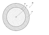
図2は、増幅用光ファイバ30の長手方向に垂直な断面の構造を示す図である。図2に示すように、増幅用光ファイバ30は、コア31と、コア31を被覆するクラッド32と、クラッド32を被覆する外側クラッド33と、外側クラッド33を被覆する被覆層34とから構成される。クラッド32の屈折率はコア31の屈折率よりも低く、外側クラッド33の屈折率はクラッド32の屈折率よりもさらに低くされている。コア31の直径は、例えば、15μmとされ、クラッド32の外径は、例えば、400μmとされる。このような、コア31を構成する材料としては、例えば、屈折率を上昇させるゲルマニウム等の元素、及び、励起光源20から出力される励起光により励起されるイッテルビウム(Yb)等の活性元素が添加された石英が挙げられる。このような活性元素としては、希土類元素が挙げられ、希土類元素としては、上記Ybの他にツリウム(Tm)、セリウム(Ce)、ネオジウム(Nd)、ユーロピウム(Eu)等が挙げられる。さらに活性元素として、希土類元素の他に、ビスマス(Bi)やクロム(Cr)等が挙げられる。また、クラッド32を構成する材料としては、例えば、何らドーパントが添加されていない純粋石英が挙げられる。また、外側クラッド33を構成する材料としては、例えば、紫外線硬化樹脂やフッ素等が添加された石英が挙げられ、被覆層34を構成する材料としては、例えば、外側クラッド33が樹脂から成る場合における樹脂とは異なる紫外線硬化樹脂が挙げられる。
FIG. 2 is a diagram illustrating a cross-sectional structure perpendicular to the longitudinal direction of the amplification
コンバイナ40は、種光用ファイバ15及びそれぞれの励起光用ファイバ22と、増幅用光ファイバ30とを接続している。具体的には、コンバイナ40において、種光用ファイバ15のコアが、増幅用光ファイバ30のコア31に端面接続されている。さらにコンバイナ40において、それぞれの励起光用ファイバ22のコアが、増幅用光ファイバ30の一端において、クラッド32に端面接続されている。こうして、種光源10から出力される種光は、増幅用光ファイバ30のコア31に入力され、励起光源20から出力される励起光は、増幅用光ファイバ30のクラッド32に入力される。
The
図3は、図1の光デリバリ部品100の拡大図である。図3に示すように、光デリバリ部品100は、放熱部材60とデリバリファイバ50とを備える。
FIG. 3 is an enlarged view of the
図4は、図3のデリバリファイバ50の長さ方向に垂直な断面の様子を示す図である。図4に示すように、デリバリファイバ50は、コア51と、コア51を被覆するクラッド52と、クラッド52を被覆する被覆層54とから構成される。コア51の直径は、例えば、増幅用光ファイバ30のコア31の直径と同様とされ、クラッド52の外径は、例えば、増幅用光ファイバ30のクラッド32の外径と同様とされ、被覆層54の外径は、例えば、増幅用光ファイバ30の被覆層34の外径と同様とされる。また、コア51の屈折率は、例えば、増幅用光ファイバ30のコア31と同様とされ、クラッド52の屈折率は、増幅用光ファイバ30のクラッド32と同様とされる。このような、コア51を構成する材料としては、例えば、屈折率を上昇させるゲルマニウム等の元素が添加された石英が挙げられ、クラッド52を構成する材料としては、例えば、何らドーパントが添加されていない純粋石英が挙げられる。また、被覆層54を構成する材料としては、例えば、ウレタン系の紫外線硬化樹脂が挙げられる。
FIG. 4 is a view showing a state of a cross section perpendicular to the length direction of the
このようなデリバリファイバ50は、図1、図3に示すように、光の入力端58側の被覆層54が所定の長さ剥離され、クラッド52が露出しており、光の入力端58が、増幅用光ファイバ30の出力端39と接続されている。そして、デリバリファイバ50は、被覆層54が剥離された部分を含む光の入力端58から所定の長さが第1光放出部50aとされ、入力端58側から第1光放出部50aに続く所定の長さが第2光放出部50bとされる。従って、本実施形態においては、第1光放出部50aにおける一部は、被覆層54が剥離されクラッド52が露出しており、他の一部は、被覆層54が剥離されていない。また、デリバリファイバ50の第2光放出部50bにおいては、被覆層54が全く剥離されていない。このように本実施形態の光デリバリ部品100においては、第1光放出部50aの一部、及び、第2光放出部50bが、クラッドが被覆層で覆われるため、光デリバリ部品100を組み立てる際、被覆54層により、コア及びクラッドが折れることを防止することができる。また、一般に光ファイバの曲げ半径が小さい個所においては、被覆層が剥離されていると、光ファイバの寿命が短くなる傾向があるが、このように被覆層54によりクラッド52が被覆されているので、デリバリファイバ50は、寿命が短くなることが防止されている。
In such a
放熱部材60は、放熱部材60の一部を構成する第1放熱部材60aと、放熱部材60の他の一部を構成する第2放熱部材60bとから成る。
The
図5は、図3のV−V線における断面の構造の様子を示す図である。図3、図5に示すように、本実施形態において、第1放熱部材60aは、凹状の第1収納部62aが形成された板状の第1基台61aと、第1収納部62aに充填された熱伝導性に優れる樹脂64とから構成される。第1基台61aを平面視する場合に、第1基台61aの外径は、略長方形の形状をしており、第1収納部62aも略長方形の形状をしている。また、第1基台61aには、第1収納部62aと連結するように、第1収納部62aの長手方向の両端部に、一対の溝部63aが形成されている。第1基台61aを構成する材料としては、特に限定されないが、アルミニウム等の金属や窒化アルミ等のセラミックを挙げることができる。また、樹脂64は、熱伝導性に優れる樹脂であることが好ましく、特に限定されないが、例えば、熱伝導性の高い材料を含有するシリコーンRTVゴム等を挙げることができる。
FIG. 5 is a diagram illustrating a cross-sectional structure taken along line VV in FIG. 3. As shown in FIGS. 3 and 5, in the present embodiment, the first
また、第2放熱部材60は、凹状の第2収納部62bが形成された第2基台61bと、第2収納部62bに充填された熱伝導性に優れる樹脂64とから構成される。第2基台61bは、断面における形状が、図5に示す第1基台61aの断面における形状と略同様とされており、外形が第1基台61aが平面上において略直角に曲がった形状とされている。また、第2収納部62bの外形は、第1収納部62aが平面上において略直角に曲がった形状とされている。また、第2基台61bには、第2収納部62bの両端と連結するように、一対の溝部63bが形成されている。なお、本実施形態においては、第2基台61bの外形、及び、第2収納部62bの外形が略直角に曲がっているが、この角度は、特に限定されるものではない。
The second
そして、デリバリファイバ50の第1光放出部50aが、第1放熱部材60aに直線状に配置されて、増幅用光ファイバ30とデリバリファイバ50の接続点が、第1放熱部材60aの第1収納部62a内に配置される。さらに、デリバリファイバ50の第1光放出部50aにおける被覆層54が剥離された部分は、第1収納部62a内に配置されて、樹脂64で被覆される。さらに、デリバリファイバ50の第1光放出部50aにおける被覆層54が剥離されていない部分は、第1収納部62a内から第2放熱部材60b側の溝部63aにかけて配置される。従って、第1収納部62a内において、第1光放出部50aにおける被覆層54が剥離されている部分は、クラッド52が樹脂64で被覆され、被覆層54が剥離されていない部分は、被覆層54が樹脂64で被覆されている。こうして、第1光放出部50aは、第1放熱部材60aに接続されている。また、第1光放出部50aにおいて、被覆層54を覆う樹脂64が、被覆層54よりも熱伝導性に優れていることが好ましい。このような場合、被覆層54において発熱する場合においても、この熱を樹脂64により、適切に伝導することができ、デリバリファイバ50をより適切に熱から保護することができる。このような樹脂としては、被覆層54がウレタン系の樹脂である場合、上述のシリコーンRTVゴム等を挙げることができる。
And the 1st
なお、デリバリファイバ50と接続されている増幅用光ファイバ30は、第1収納部62aからデリバリファイバ50が配置される側の溝部63aと反対側の溝部63aに配置されており、放熱部材60から導出されている。
The amplification
また、デリバリファイバ50の第2光放出部50bは、第2放熱部材60bにおいて、第1放熱部材60a側の溝部63bから第2収納部62b内に配置されて、さらに、第2収納部62bから第1放熱部材60a側と反対側の溝部63bに配置される。つまり、デリバリファイバ50の第2光放出部50bは、略直角に曲がった形状の第2基台61bに沿って曲げられて配置される。なお、本実施形態においては、第2光放出部50bは、一定の曲げ半径で略直角に曲げられて配置されている。また、第2光放出部50bにおいては、被覆層54が剥離されていないため、第2収納部62b内において、被覆層54が樹脂64で被覆されている。こうして、第2光放出部50bは、第2放熱部材60bに接続されている。また、第2光放出部50bにおいても、上述の第1光放出部50aと同様に、被覆層54を覆う樹脂64が、被覆層54よりも熱伝導性に優れていることが好ましい。このような場合、被覆層54において発熱する場合においても、この熱を樹脂64により、適切に伝導することができ、デリバリファイバ50をより適切に熱から保護することができる。そして、デリバリファイバ50の第2光放出部に続く部分が、放熱部材60の外に導出されている。なお、本実施形態においては、上述のように、第1光放出部50aが直線状であるため、第1光放出部50aの曲げ半径は、無限大と考えることができる。従って、第1光放出部50aは、第2光放出部50bよりも曲げ半径が大きくされる。なお、本実施形態においては、第2光放出部50bが略直角に曲がっているが、この角度は、特に限定されるものではない。
Further, the second
また、本実施形態においては、デリバリファイバ50の増幅用光ファイバ30側と反対側の端部には何も接続されておらず、光が出力される出力端とされる。ただし、この出力端には、出力光の径を広げるためのガラスロッドから成るエンドキャップが接続されても良い。
Further, in the present embodiment, nothing is connected to the end of the
このようなレーザ装置1は、次のように動作する。 Such a laser device 1 operates as follows.
まず、種光源10から種光が出力されると共に、励起光源20から励起光が出力される。このとき種光源10から出力される種光は、上述のように、例えば、波長が1070nmとされる。種光源10から出力された種光は、種光用ファイバ15のコアを伝播して、コンバイナ40に入力する。
First, seed light is output from the seed light source 10 and excitation light is output from the
一方、励起光源20のそれぞれのレーザダイオード21から出力される励起光は、上述のように、例えば、波長が915nmとされる。それぞれのレーザダイオード21から出力された励起光は、励起光用ファイバ22を伝播しコンバイナ40に入力する。
On the other hand, the excitation light output from each
こうしてコンバイナ40に入力した種光は、増幅用光ファイバ30のコア31に入力して、コア31を伝播する。一方、コンバイナ40に入力した励起光は、増幅用光ファイバ30のクラッド32に入力して、クラッド32を主に伝播する。
The seed light thus input to the
そして、増幅用光ファイバ30において、励起光がコア31を通過するときに、コア31に添加されている活性元素に吸収されて、活性元素を励起する。励起された活性元素は、誘導放出を起こし、この誘導放出により種光が増幅されて、出力光として増幅用光ファイバ30の出力端39から出力される。
In the amplification
そして、増幅用光ファイバ30のコア31から出力した出力光は、デリバリファイバ50の入力端58からコア51に入力し、コア51を伝播して、デリバリファイバ50の出力端から出力される。
The output light output from the
ところで、上記の様に出力光が増幅用光ファイバ30のコア31からデリバリファイバ50のコア51に入力するときに、入力端58において、増幅用光ファイバ30のコア31とデリバリファイバ50のコア51との軸ずれ・角度ずれや、増幅用光ファイバ30とデリバリファイバ50のモードフィールドの不整合等により、出力光が漏えいして、漏れ光としてクラッド52に入力する場合がある。また、増幅用光ファイバ30において、活性元素に吸収されずに増幅用光ファイバ30の出力端39から出力される余剰励起光が、デリバリファイバ50のクラッド52に入力する場合がある。
By the way, when the output light is input from the
一般的に、励起光は比較的NAが大きな光から成り、種光が増幅された出力光は、NAが小さな光から大きな光まで含む。従って、上記の様に出力光や励起光がデリバリファイバ50のクラッド52に入力する場合、この光は、NAの大きな光から小さな光まで含む。
In general, excitation light is composed of light having a relatively large NA, and output light obtained by amplifying seed light includes light having a small NA and light having a large NA. Therefore, when output light or excitation light is input to the clad 52 of the
そして、クラッド52に入力した光の内、NAの比較的大きな光は、クラッド52の外周面に対する入射角が小さいため、クラッド52の外周面から出力され易い。このため、このNAの比較的大きな光の少なくとも一部は、デリバリファイバ50の第1光放出部50aにおいてクラッド52から放出され熱に変化する。この熱は、第1放熱部材60aにおける樹脂64を伝導して、第1基台61aを介して外部に放出される。なお、上述のように、第1光放出部50aにおける被覆層54を覆う樹脂64が、被覆層54よりも熱伝導性に優れていれば、第1光放出部50aにおいて被覆層54が発熱する場合においても、この熱を樹脂64により、適切に伝導することができ、デリバリファイバ50をより適切に熱から保護することができる。
Of the light input to the clad 52, light having a relatively large NA is likely to be output from the outer peripheral surface of the clad 52 because the incident angle with respect to the outer peripheral surface of the clad 52 is small. For this reason, at least a part of the light having a relatively large NA is emitted from the clad 52 in the first
一方、NAの比較的小さな光は、クラッド52の外周面に対する入射角が大きいため、直線状である第1光放出部50aにおいて、クラッド52から放出されづらく、第1光放出部50aを通過する。また、NAの比較的大きな光においても、一部の光は、第1光放出部50aを通過する。こうして、クラッド52を伝播する光の内、第1光放出部50aを通過した光は、第2光放出部50bまで伝播する。しかし、第2光放出部50bは、第1光放出部50aよりも曲げ半径が小さいため、NAの比較的小さな光もクラッド52から放出され易い。そのため、クラッド52を伝播する光の内、第2光放出部50bに到達した光の多くは、第2光放出部50bにおいて、クラッド52から放出される。なお、本実施形態においては、第2光放出部50bにおいては、クラッド52が被覆層54で覆われており、クラッド52から放出された光の一部が被覆層54で熱とされる。しかし、クラッド52に入力した光の内、一部の光は、第1光放出部50aにおいて、放出されているため、第2光放出部50bにおいて被覆層54で発生する熱量は、被覆層54を損傷するほど大きくない。さらに第2光放出部50bにおいて被覆層54は、第2放熱部材60bに接続されているため、被覆層54は熱による損傷を受けづらい。特に上述のように、第2光放出部50bにおける被覆層54を覆う樹脂64が、被覆層54よりも熱伝導性に優れていれば、第2光放出部50bにおいて被覆層54が発熱する場合においても、この熱を樹脂64により、適切に伝導することができ、デリバリファイバ50をより適切に熱から保護することができる。そして、被覆層54で発生した熱は、樹脂64を伝導して、第2基台61bを介して外部に放出される。
On the other hand, light having a relatively small NA has a large incident angle with respect to the outer peripheral surface of the clad 52, so that it is difficult to be emitted from the clad 52 in the linear first
以上説明したように、本実施形態の光デリバリ部品100によれば、デリバリファイバ50のクラッド52にNAの小さな光とNAの大きな光とを有する光が入力すると、この光は、第1光放出部50a、第2光放出部50bの順に伝播する。励起光のようなNAの大きな光は、デリバリファイバ50のクラッド52の外周面に対する入射角が小さく、クラッド52から放出され易い。一方、種光が増幅された出力光に含まれるNAの小さな光は、デリバリファイバ50のクラッド52の外周面に対する入射角が大きく、クラッド52から放出されづらい。従って、本実施形態の光デリバリ部品100においては、第1光放出部50aが、第2光放出部50bよりも大きな曲げ半径とされるため、クラッド52に入力した光の内、励起光や出力光の一部のような比較的NAの大きな光が第1光放出部50aから放出される。そして、第2光放出部50bは、第1光放出部50aよりも曲げ半径が小さいため、比較的NAの大きな光も比較的NAの小さな光も放出することができる。従って、第2光放出部50bにおいては、第1光放出部50aを通過した残りの光が放出される。そして、第1光放出部50aから放出される光により発生する熱は、第1放熱部材60aから放熱され、第2光放出部50bから放出される光により発生する熱は、第2放熱部材60bから放熱される。このようにNAの比較的大きな光と、NAの比較的小さな光を含む光とを異なる場所で放出して、それぞれ発熱させることにより、発熱する場所が集中することを防止でき、分散して発熱した熱をそれぞれ適切に放出することができる。従って、熱による損傷を防止することができる。
As described above, according to the
従って、このような光デリバリ部品100を用いるレーザ装置1は、高い信頼性を有することができる。特に本実施形態のようにレーザ装置1が増幅用光ファイバ30を用いるファイバレーザ装置である場合においては、増幅用光ファイバ30から出力される余剰励起光が、デリバリファイバ50のクラッド52に入力されたり、種光が増幅された出力光の一部がクラッド52に入力する場合があるが、このような場合においても、余剰励起光の多くは第1光放出部50aにおいて放出され、クラッド52に入力した出力光の多くは、第2光放出部50bから出力される。従って、クラッド52に入力した励起光と信号光とを分散して熱に変換することができるので、信頼性の高いファイバレーザ装置とすることができる。
Therefore, the laser device 1 using such an
また、本実施形態の光デリバリ部品100においては、第1光放出部50aが直線状とされるので、NAの小さな光を適切に第2光放出部50bまで伝播させることができ、第1光放出部50a及び第2光放出部50bにおいて、より適切に発生する熱を分散することができる。そして、第2光放出部50bが、一定の曲げ半径で曲げられているので、第2光放出部50bと接続される第2放熱部材60bを一定の曲げ変形で加工することができる。特に、第2基台61bが、アルミ等の熱伝導性の良い金属から成る場合、フライス盤等の金属加工機で加工が簡単になるため、第2収納部62bの形成も容易となり、安価に放熱部材60を製造することができる。
Further, in the
なお、本実施形態のレーザ装置1においては、増幅用光ファイバ30とデリバリファイバ50との間に他の光ファイバが設けられても良い。この光ファイバは、コア及びクラッドを有し、例えば、種光用ファイバ15と同じ構成、或いは、コア及びクラッド及び外側クラッドを有するダブルクラッドファイバとされる。この光ファイバがダブルクラッドファイバである場合、このダブルクラッドファイバは、コアに活性元素が添加されないこと以外は、増幅用光ファイバ30と同様の構成とされれば良い。この場合、増幅用光ファイバ30の出力端が、光ファイバの入力端に接続され、光ファイバの出力端がデリバリファイバの入力端に接続されることになる。
In the laser device 1 of the present embodiment, another optical fiber may be provided between the amplification
(第2実施形態)
次に、本発明の第2実施形態について図6を参照して詳細に説明する。なお、第1実施形態と同一又は同等の構成要素については、特に説明する場合を除き、同一の参照符号を付して重複する説明は省略する。図6は、本発明の第2実施形態に係る光デリバリ部品101の拡大図である。
(Second Embodiment)
Next, a second embodiment of the present invention will be described in detail with reference to FIG. In addition, about the component which is the same as that of 1st Embodiment, or equivalent, except the case where it demonstrates especially, the same referential mark is attached | subjected and the overlapping description is abbreviate | omitted. FIG. 6 is an enlarged view of the
本実施形態の光デリバリ部品101は、第1光放出部50aにおいて、デリバリファイバ50が直線状に配置される点は、第1実施形態における光デリバリ部品100と同様であるが、第2光放出部50bにおいて、デリバリファイバ50が、第1光放出部側から徐々に曲げ半径が小さくされて配置される点において、第1実施形態の光デリバリ部品100と異なる。そして、このデリバリファイバ50の曲げに沿うように、第1放熱部材60aの第1基台61a及び第2放熱部材60bの第2基台61bの外形が平面方向に曲げられており、これに伴い第1収納部62a及び第2収納部62bの外形が平面方向に曲げられている。
The
本実施形態の光デリバリ部品101によれば、第2光放出部内において、NAの比較的大きな光からNAの比較的小さな光まで、順に徐々に放出される。従って、第1光放出部で放出されなかった比較的NAの大きな光が第2光放出部に伝播する場合においても、第2光放出部において、まずNAの比較的大きな光を放出して、次いで、比較的NAの小さな光を放出することができる。こうして、第2光放出部において、発熱する個所を第1実施形態の光デリバリ部品100よりも更に分散することができ、熱による損傷をより適切に防止することができる。
According to the
(第3実施形態)
次に、本発明の第3実施形態について図7を参照して詳細に説明する。なお、第1実施形態と同一又は同等の構成要素については、特に説明する場合を除き、同一の参照符号を付して重複する説明は省略する。図7は、本発明の第3実施形態に係る光デリバリ部品102の拡大図である。
(Third embodiment)
Next, a third embodiment of the present invention will be described in detail with reference to FIG. In addition, about the component which is the same as that of 1st Embodiment, or equivalent, except the case where it demonstrates especially, the same referential mark is attached | subjected and the overlapping description is abbreviate | omitted. FIG. 7 is an enlarged view of the
図7に示すように、本実施形態の光デリバリ部品102は、第1光放出部50aから第2光放出部50bにかけて、デリバリファイバ50の曲げ半径が徐々に小さくされている。従って、第1実施形態の光デリバリ部品100においては、第1光放出部50aにおいてデリバリファイバ50が直線状に配されているのに対し、本実施形態の光デリバリ部品102においては、第1光放出部50aにおいてデリバリファイバ50が曲げられている。
そして、このデリバリファイバ50の曲げに沿うように、第1放熱部材60aの第1基台61a及び第2放熱部材60bの第2基台61bの外形が平面方向に曲げられており、これに伴い第1収納部62a及び第2収納部62bの外形が平面方向に曲げられている。
As shown in FIG. 7, in the
Then, along the bending of the
本実施形態の光デリバリ部品102によれば、デリバリファイバ50の曲げ半径が、第1光放出部50aから第2光放出部50bにかけて徐々に小さくされることで、NAの比較的大きな光からNAの比較的小さな光まで、光を順に徐々に放出することができる。従って、発熱する個所を第1実施形態の光デリバリ部品100と比べて更に分散することができ、熱による損傷をより適切に防止することができる。
According to the
(第4実施形態)
次に、本発明の第4実施形態について図8を参照して詳細に説明する。なお、第1実施形態と同一又は同等の構成要素については、同一の参照符号を付して特に説明する場合を除き重複する説明は省略する。図8は、本実施形態に係るレーザ装置2を示す図である。
(Fourth embodiment)
Next, a fourth embodiment of the present invention will be described in detail with reference to FIG. In addition, about the component which is the same as that of 1st Embodiment, or an equivalent component, the overlapping description is abbreviate | omitted except the case where it attaches | subjects the same referential mark and demonstrates especially. FIG. 8 is a diagram showing the
図8に示すように、本実施形態のレーザ装置2は、第1実施形態における励起光源20と同様の構成の励起光源20a、20bと、増幅用光ファイバ30と、増幅用光ファイバ30の両端に設けられ、第1実施形態におけるコンバイナ40と同様の構成のコンバイナ40a、40bと、コンバイナ40aに接続される第1共振用ファイバ16と、第1共振用ファイバ16に接続され、第1実施形態における光デリバリ部品100と同様の構成の光デリバリ部品100aと、コンバイナ40bに接続される第2共振用ファイバ18と、第2共振用ファイバ18に接続され、第1実施形態における光デリバリ部品100と同様の構成の光デリバリ部品100bと、第1共振用ファイバ16に設けられる第1ミラーとしての第1FBG(Fiber Bragg Grating)71と、第2共振用ファイバ18に設けられる第2ミラーとしての第2FBG72と、を主な構成として備える。
As shown in FIG. 8, the
コンバイナ40aは、第1実施形態のコンバイナ40と同様にして、増幅用光ファイバ30の端部に設けられている。また、コンバイナ40bは、増幅用光ファイバ30のコンバイナ40aが設けられる端部と反対側の端部に設けられている。
The
励起光源20aのそれぞれのレーザダイオード21は、第1実施形態と同様にして励起光用ファイバ22に接続されており、これらの励起光用ファイバ22は、コンバイナ40aにおいて、増幅用光ファイバ30のクラッド32に接続されている。従って、励起光源20aから出力される励起光は、コンバイナ40aを介して、増幅用光ファイバ30のクラッド32に入力する。
Each
また、第1共振用ファイバ16は、コア及びクラッドを有し、例えば、第1実施形態における種光用ファイバ15と同じ構成、或いは、コア及びクラッド及び外側クラッドを有するダブルクラッドファイバとされる。第1共振用ファイバがダブルクラッドファイバである場合、このダブルクラッドファイバは、増幅用光ファイバと同様の構成、或いは、コアに活性元素が添加されない構成とされる。第1共振用ファイバ16は、コンバイナ40aにおいて、増幅用光ファイバ30に接続され、増幅用光ファイバ30のコア31と第1共振用ファイバ16のコアとが結合している。また、第1共振用ファイバ16のコアには、第1FBG71が設けられており、第1FBG71は、増幅用光ファイバ30のコア31と結合している。第1FBG71は、増幅用光ファイバ30のコア31に添加されている活性元素が励起状態とされた場合に放出する自然放出光の一部の波長と同じ波長の光を反射し、反射率が、例えば100%とされる。また、第1共振用ファイバ16の増幅用光ファイバ30側と反対側には、光デリバリ部品100aのデリバリファイバ50の入力端58が接続されている。さらに光デリバリ部品100aのデリバリファイバ50には、終端部材17が接続されている。
The
また、励起光源20bのそれぞれのレーザダイオード21は、第1実施形態と同様にして励起光用ファイバ22に接続されており、これらの励起光用ファイバ22は、コンバイナ40bにおいて、増幅用光ファイバ30のクラッド32に接続されている。従って、励起光源20bから出力される励起光は、コンバイナ40bを介して、増幅用光ファイバ30のクラッド32に入力する。
Further, each
また、第2共振用ファイバ18は、コア及びクラッドを有し、例えば、第1実施形態における種光用ファイバ15と同じ構成、或いは、コア及びクラッド及び外側クラッドを有するダブルクラッドファイバとされる。第2共振用ファイバがダブルクラッドファイバである場合、このダブルクラッドファイバは、増幅用光ファイバと同様の構成、或いは、コアに活性元素が添加されない構成とされる。そして、第2共振用ファイバ18は、コンバイナ40bにおいて、増幅用光ファイバ30に接続され、増幅用光ファイバ30のコア31と第2共振用ファイバ18のコアとが結合している。また、第2共振用ファイバ18のコアには、第2FBG72が設けられており、第2FBG72は、増幅用光ファイバ30のコア31と結合している。第2FBG72は、第1FBG71が反射する光と同じ波長の光を第1FBG71よりも低い反射率で反射する。第2FBGの反射率は、例えば30%とされる。また、第2共振用ファイバ18の増幅用光ファイバ30側と反対側には、光デリバリ部品100bのデリバリファイバ50の入力端58が接続されている。
The
このように本実施形態のレーザ装置2は、増幅用光ファイバ30の前方側及び後方側の双方から励起光を入力する双方励起であって、第1、第2FBG71、72で共振を行うファブリペロー型のファイバレーザ装置とされる。
As described above, the
このようなレーザ装置2においては、まず、励起光源20a、20bのそれぞれのレーザダイオード21から励起光が出力される。それぞれのレーザダイオード21から出力される励起光は、第1実施形態のレーザ装置1と同様に、例えば、波長が915nmとされる。そして、それぞれのレーザダイオード21から出力された励起光は、それぞれの励起光用ファイバ22を介して、増幅用光ファイバ30の前方側、及び、後方側からクラッド32に入力する。増幅用光ファイバ30のクラッドに入力した励起光は、クラッド32を主に伝播する。そして、コア31を通過するときにコア31に添加されている活性元素に吸収されて、活性元素を励起状態にする。
In such a
こうして励起光により励起状態とされた活性元素から自然放出光が放出され、この自然放出光を元にして第1FBG71と第2FBG72との間で光の共振が起こる。共振する光は、第1FBG71及び第2FBG72の反射波長と同じ波長であり、この共振する光が、被増幅光として増幅用光ファイバ30において励起された活性元素の誘導放出により増幅される。そして、増幅された光の一部が、第2FBG72を透過して、出力光(信号光)として第2共振用ファイバから出力され、光デリバリ部品100bのデリバリファイバ50に入力する。このとき、第2共振用ファイバからデリバリファイバ50に光が入力するときに、励起光源20aから出力され、増幅用光ファイバ30において吸収されずに、増幅用光ファイバ30から出力される余剰励起光や、出力光がデリバリファイバ50のクラッド52に入力する場合がある。しかし、第1実施形態の光デリバリ部品100と同様にして、これらの光は、熱に変換される。そして、光デリバリ部品100bにおけるデリバリファイバ50のコア51を伝播する光は、デリバリファイバ50から出力される。
In this way, spontaneous emission light is emitted from the active element that has been excited by the excitation light, and light resonance occurs between the
また、励起光源20bから出力され、増幅用光ファイバ30において吸収されずに、増幅用光ファイバ30から出力される余剰励起光や、共振する光の一部が、第1FBG71を透過する場合がある。このような光は、第1共振用ファイバ16から出力され、光デリバリ部品100aのデリバリファイバ50に入力する。この場合においても、第1共振用ファイバ16からデリバリファイバ50に光が入力するときに、デリバリファイバ50のクラッド52に光が入力する場合がある。しかし、第1実施形態の光デリバリ部品100と同様にして、この光は、熱に変換される。そして、光デリバリ部品100aにおけるデリバリファイバ50のコア51を伝播する光は、終端部材17において熱に変換される。
In addition, there is a case where surplus pumping light output from the amplifying
このように増幅用光ファイバ30から出力される光は、第1、第2共振用ファイバ16、18に入力するため、そのような観点において、本実施形態では、増幅用光ファイバの両端を出力端と考えることができ、光ファイバである第1、第2共振用ファイバ16、18の入力端が増幅用光ファイバ30の出力端に接続されているとすることができる。そして、第1、第2共振用ファイバ16、18は、増幅用光ファイバ30から出力される光を伝播、出力して、光デリバリ部品100a、100bのデリバリファイバ50の入力端に入力するため、第1、第2共振用ファイバ16、18の出力端がデリバリファイバ50の入力端58に接続されていると考えることができる。
Since the light output from the amplification
本実施形態のレーザ装置2によれば、第1、第2共振用ファイバ16、18から光が出力され、光デリバリ部品100a、100bのデリバリファイバ50のクラッド52に入力する場合においても、これらの光は第1光放出部50a、第2光放出部50bから出力される。従って、クラッド52に入力した光を分散して熱に変換することができるので、信頼性の高いレーザ装置とすることができる。特に本実施形態のレーザ装置2の様な双方励起型のファイバレーザ装置においては、増幅用光ファイバ30の両側から余剰励起光が出力される傾向があるため、本実施形態のレーザ装置2の様に、増幅用光ファイバの両側に光デリバリ部品100a、100bを配置することが好ましい。
According to the
なお、本実施形態のレーザ装置2においては、光デリバリ部品100a、100bに代えて、第2実施形態、第3実施形態の光デリバリ部品101、102を用いても良い。
In the
以上、本発明について、第1〜第4実施形態を例に説明したが、本発明はこれらに限定されるものではない。 As mentioned above, although this invention was demonstrated to the 1st-4th embodiment as an example, this invention is not limited to these.
例えば、上記実施形態において、第1光放出部50aの一部において、被覆層54が剥離されたが、被覆層54の剥離は本質的なものではなく、被覆層54は、第1光放出部50a及び第2光放出部50bの全てに渡って剥離されても良く、剥離されていなくても良い。
For example, in the above embodiment, the covering
また、被覆層54は、光透過性の樹脂から構成されていても良い。この場合、被覆層54をウレタン系の樹脂で構成すれば良い。この場合、第1光放出部50a及び第2光放出部50bにおける被覆層54が剥離されていない場所において、クラッド52を伝播する光は、被覆層54を透過して放出されるので、クラッド52と離れた場所において発熱するためデリバリファイバ50を適切に保護することができる。
The
更に、樹脂64が光透過性の樹脂であっても良い。この場合、第1光放出部50a及び第2光放出部50bにおいて、デリバリファイバ50から放出される光は、樹脂64を伝播しながら熱に変換されたり、樹脂64を伝播して第1基台61a、第2基台61bで熱に変換されたりする。また、上述のように被覆層54が光透過性の樹脂である場合、被覆層54を透過した光は、樹脂64を伝播しながら熱に変換されたり、樹脂64を伝播して第1基台61a、第2基台61bで熱に変換されたりする。このような光透過性の樹脂64としては、エポキシ樹脂を挙げることができる。
Further, the
また、上記実施形態において、レーザ装置をファイバレーザ装置を例に説明したが、本発明はこれに限らず、例えば、光ファイバを有しこの光ファイバから光を出力する固体レーザ装置に用いる光デリバリ部品として、上記実施形態の光デリバリ部品を用いても良い。 Further, in the above embodiment, the laser device has been described by taking the fiber laser device as an example. However, the present invention is not limited to this, and for example, an optical delivery used in a solid-state laser device that has an optical fiber and outputs light from the optical fiber. As the component, the light delivery component of the above embodiment may be used.
また、上記実施形態において、レーザ装置1は、増幅用光ファイバ30の一方側から励起光を入力し、レーザ装置2は、増幅用光ファイバ30の双方から励起光を入力したが、レーザ装置1、2において、励起光は、増幅用光ファイバ30のどちらか一方から入力しても良く、双方から入力しても良い。
In the above embodiment, the laser device 1 inputs pumping light from one side of the amplification
また、第1基台61a、第2基台61bをより冷却する目的で、第1基台61a、第2基台61bにヒートシンク用のフィンが設けられても良く、第1基台61a、第2基台61bがヒートパイプが設けられても良い。
Further, for the purpose of further cooling the
以下、実施例及び比較例を挙げて本発明の内容をより具体的に説明するが、本発明はこれに限定されるものでは無い。 Hereinafter, the content of the present invention will be described more specifically with reference to Examples and Comparative Examples, but the present invention is not limited thereto.
(実施例1)
第1実施形態と同様の光デリバリ部品を作製した。図1のレーザ装置の構成でダブルクラッドファイバである増幅用光ファイバの出力端にシングルクラッドファイバであるデリバリファイバを接続して、端部から約20mmだけ被覆層を剥離した。次に、凹状の第1収納部が形成された金属製の板から成る第1基台、及び、凹状の第2収納部が形成された金属製の板から成り、平面状に曲がっている第2基台を準備した。そして、デリバリファイバを直線状に端部から約50mm第1基台に配置して、収容部に熱伝導性の樹脂を充填することでデリバリファイバの外周面をこの樹脂で覆った。さらに、デリバリファイバの第1基台に配置された部分に続く部分を、一定の曲げ半径80mmで長さ240mmに渡り、第2基台に配置して、収容部に光熱伝導性の樹脂を充填することでデリバリファイバの外周面をこの樹脂で覆った。
Example 1
An optical delivery component similar to that of the first embodiment was produced. In the configuration of the laser device of FIG. 1, a delivery fiber as a single clad fiber was connected to the output end of an amplification optical fiber as a double clad fiber, and the coating layer was peeled off by about 20 mm from the end. Next, a first base made of a metal plate with a concave first storage part and a metal plate with a concave second storage part formed and bent in a planar shape. Two units were prepared. Then, the delivery fiber was linearly arranged on the first base about 50 mm from the end portion, and the outer peripheral surface of the delivery fiber was covered with this resin by filling the accommodating portion with a heat conductive resin. Furthermore, the portion following the portion arranged on the first base of the delivery fiber is arranged on the second base over a length of 240 mm with a constant bending radius of 80 mm, and the housing portion is filled with photothermal conductive resin. Thus, the outer peripheral surface of the delivery fiber was covered with this resin.
次に、このデリバリファイバの端部から300Wの光を入力した。すると、デリバリファイバにおける第1基台に配置された直線状の部分の温度が68℃となり、第2基台に配置された部分の曲げ始めの部分の温度が約80℃となり、第2基台に配置された部分の曲げ終わり部分の温度が約40℃となった。 Next, 300 W of light was input from the end of this delivery fiber. Then, the temperature of the linear portion arranged on the first base in the delivery fiber becomes 68 ° C., the temperature of the part at the beginning of bending of the portion arranged on the second base becomes about 80 ° C., and the second base The temperature of the bending end portion of the portion arranged in (4) was about 40 ° C.
(実施例2)
第2実施形態と同様の光デリバリ部品を作製した。デリバリファイバの第2基台に配置される曲げ始めの曲げ半径を160mmとして、曲げ終わりの半径を80mmとしたこと以外は、実施例1と同様にした。
(Example 2)
An optical delivery component similar to that of the second embodiment was produced. The same procedure as in Example 1 was performed except that the bending radius at the beginning of bending disposed on the second base of the delivery fiber was 160 mm and the radius at the end of bending was 80 mm.
次に、このデリバリファイバの端部から実施例1と同様の強度の光を実施例1と同様の条件で入力した。すると、デリバリファイバにおける第1基台に配置された直線状の部分の温度が65℃となり、第2基台に配置された部分の曲げ始めの部分の温度が約60℃となり、第2基台に配置された部分の曲げ終わり部分の温度が約60℃となった。 Next, light having the same intensity as in Example 1 was input from the end of this delivery fiber under the same conditions as in Example 1. Then, the temperature of the linear portion arranged on the first base in the delivery fiber becomes 65 ° C., the temperature of the portion at the beginning of bending of the portion arranged on the second base becomes about 60 ° C., and the second base The temperature of the bending end portion of the portion arranged in (1) was about 60 ° C.
(比較例1)
第1基台に実施例1と同様にデリバリファイバを配置して、第2基台にデリバリファイバを配置しないこと以外は実施例1と同様にして光デリバリ部品を作製した。
(Comparative Example 1)
An optical delivery component was produced in the same manner as in Example 1 except that the delivery fiber was disposed on the first base in the same manner as in Example 1, and the delivery fiber was not disposed on the second base.
そして、このデリバリファイバの端部から約50Wの光を実施例1と同様の条件で入力した。すると、デリバリファイバにおける第1基台に配置された直線状の部分の温度が60℃となり、デリバリファイバの端部から約数十cm離れた場所において、デリバリファイバが曲がっている場所において、約100度となり、デリバリファイバの被覆層を損傷した。 Then, about 50 W of light was input from the end of this delivery fiber under the same conditions as in Example 1. Then, the temperature of the linear portion arranged on the first base in the delivery fiber becomes 60 ° C., and at the place where the delivery fiber is bent at a place about several tens of centimeters away from the end of the delivery fiber, about 100 The coating layer of the delivery fiber was damaged.
以上より、本発明によれば、デリバリファイバのクラッドに入力した光が分散して出力し、熱が発生する場所が分散する結果となった。従って、本発明の光デリバリ部品、及び、それを用いたレーザ装置は、熱による損傷を防止できると考えられる。 As described above, according to the present invention, the light input to the clad of the delivery fiber is dispersed and output, and the place where heat is generated is dispersed. Therefore, it is considered that the optical delivery component of the present invention and the laser device using the same can prevent damage due to heat.
以上説明したように、本発明によれば、熱による損傷を防止することができる光デリバリ部品、及び、それを用いたレーザ装置が提供される。 As described above, according to the present invention, an optical delivery component capable of preventing damage due to heat and a laser apparatus using the same are provided.
1、2・・・レーザ装置
10・・・種光源
15・・・種光用ファイバ
16・・・第1共振用ファイバ
18・・・第2共振用ファイバ
20、20a、20b・・・励起光源
21・・・レーザダイオード
22・・・励起光用ファイバ
30・・・増幅用光ファイバ
31・・・コア
32・・・クラッド
33・・・樹脂クラッド
34・・・被覆層
39・・・出力端
40、40a、40b・・・コンバイナ
50・・・デリバリファイバ
50a・・・第1光放出部
50b・・・第2光放出部
51・・・コア
52・・・クラッド
54・・・被覆層
60・・・放熱部材
60a・・・第1放熱部材
60b・・・第2放熱部材
61a・・・第1基台
61b・・・第2基台
62a・・・第1収納部
62b・・・第2収納部
64・・・樹脂
71・・・第1ミラー(第1FBG)
72・・・第2ミラー(第2FBG)
100、100a、100b、101、102・・・光デリバリ部品
DESCRIPTION OF
72 ... 2nd mirror (2nd FBG)
100, 100a, 100b, 101, 102 ... optical delivery parts
Claims (8)
放熱部材と、
を備え、
前記デリバリファイバは、前記放熱部材の一部に接続され前記クラッドから光を放出させる第1光放出部と、前記放熱部材の他の一部に接続され前記クラッドから光を放出させる第2光放出部とを有すると共に、少なくとも第2光放出部が曲げられており、
前記第1光放出部は、前記第2光放出部よりもデリバリファイバにおける光の入力端側に設けられ、前記第1光放出部の全長における前記クラッドから光を放出させ、
前記デリバリファイバは、前記クラッドを覆う被覆層をさらに有し、前記第2光放出部における前記クラッドは前記被覆層で覆われ、前記第1光放出部における入力端から少なくとも前記クラッドの一部は前記被覆層から露出され、
前記被覆層から露出されるクラッドの入力端には、光を出力する他の光ファイバの出力端が接続され、
前記第1光放出部は、前記第2光放出部よりもNAの大きい光が放出されるよう直線状とされ、
前記第2光放出部は、前記第1光放出部よりもNAの小さい光が徐々に放出されるよう前記第1光放出部側から徐々に曲げ半径が小さくされる
ことを特徴とする光デリバリ部品。 A delivery fiber having a core and a cladding;
A heat dissipating member;
With
The delivery fiber is connected to a part of the heat radiating member to emit light from the clad, and the second light emission is connected to another part of the heat radiating member to emit light from the clad. And at least the second light emitting portion is bent,
The first light emitting unit, the provided et is the input end side of the light in the delivery fiber than the second light emitting portion to release the light from the cladding in the entire length of the first light emitting unit,
The delivery fiber further includes a coating layer covering the cladding, the cladding in the second light emitting portion is covered with the coating layer, and at least a part of the cladding from the input end in the first light emitting portion. Exposed from the coating layer;
The input end of the cladding exposed from the coating layer is connected to the output end of another optical fiber that outputs light ,
The first light emitting part is linear so that light having a larger NA than the second light emitting part is emitted ;
The second light emitting unit has an optical delivery characterized in that a bending radius is gradually decreased from the first light emitting unit side so that light having a smaller NA than that of the first light emitting unit is gradually emitted. parts.
放熱部材と、
を備え、
前記デリバリファイバは、前記放熱部材の一部に接続され前記クラッドから光を放出させる第1光放出部と、前記放熱部材の他の一部に接続され前記クラッドから光を放出させる第2光放出部とを有すると共に、少なくとも第2光放出部が曲げられており、
前記第1光放出部は、前記第2光放出部よりもデリバリファイバにおける光の入力端側に設けられ、前記第1光放出部の全長における前記クラッドから光を放出させ、
前記デリバリファイバは、前記クラッドを覆う被覆層をさらに有し、前記第2光放出部における前記クラッドは前記被覆層で覆われ、前記第1光放出部における入力端から少なくとも前記クラッドの一部は前記被覆層から露出され、
前記被覆層から露出されるクラッドの入力端には、光を出力する他の光ファイバの出力端が接続され、
NAの相違する光が徐々に放出されるよう前記デリバリファイバの前記曲げ半径が前記第1光放出部から前記第2光放出部にかけて徐々に小さくされる
ことを特徴とする光デリバリ部品。 A delivery fiber having a core and a cladding;
A heat dissipating member;
With
The delivery fiber is connected to a part of the heat radiating member to emit light from the clad, and the second light emission is connected to another part of the heat radiating member to emit light from the clad. And at least the second light emitting portion is bent,
The first light emitting unit, the provided et is the input end side of the light in the delivery fiber than the second light emitting portion to release the light from the cladding in the entire length of the first light emitting unit,
The delivery fiber further includes a coating layer covering the cladding, the cladding in the second light emitting portion is covered with the coating layer, and at least a part of the cladding from the input end in the first light emitting portion. Exposed from the coating layer;
The input end of the cladding exposed from the coating layer is connected to the output end of another optical fiber that outputs light ,
An optical delivery component characterized in that the bending radius of the delivery fiber is gradually reduced from the first light emitting portion to the second light emitting portion so that light having different NA is gradually emitted .
前記第1光放出部において少なくとも前記被覆層から露出される前記クラッドの一部は、前記光透過性の樹脂で覆われる
ことを特徴とする請求項1または2に記載の光デリバリ部品。 The heat radiation member further includes a light transmitting resin covering the delivery fiber,
Wherein the portion of the cladding which is exposed from at least the coating layer in the first light emitting unit, the light delivery component according to claim 1 or 2, characterized in that is covered with the light transmitting resin.
前記第1光放出部及び前記第2光放出部の少なくとも一部において、前記被覆層が前記樹脂で覆われ、
前記被覆層及び前記樹脂は、共に光透過性である
ことを特徴とする請求項3に記載の光デリバリ部品。 The heat dissipation member further includes a resin that covers the delivery fiber,
In at least a part of the first light emitting part and the second light emitting part, the covering layer is covered with the resin,
The light delivery component according to claim 3 , wherein the coating layer and the resin are both light transmissive.
前記第1光放出部及び前記第2光放出部の少なくとも一部において、前記被覆層が前記樹脂で覆われ、
前記樹脂は、前記被覆層よりも熱伝導性に優れる
ことを特徴とする請求項3に記載の光デリバリ部品。 The heat dissipation member further includes a resin that covers the delivery fiber,
In at least a part of the first light emitting part and the second light emitting part, the covering layer is covered with the resin,
The light delivery component according to claim 3 , wherein the resin is more excellent in thermal conductivity than the coating layer.
コアとクラッドとを有し、光を出力する光ファイバと、
を備え、
前記光ファイバの出力端が前記デリバリファイバの前記入力端に接続される
ことを特徴とするレーザ装置。 The light delivery component according to any one of claims 1 to 5 ,
An optical fiber having a core and a cladding and outputting light;
With
An output end of the optical fiber is connected to the input end of the delivery fiber.
前記光ファイバは、前記励起光源から出力される励起光により励起状態とされる活性元素が前記コアに添加される増幅用光ファイバであることを特徴とする請求項6に記載のレーザ装置。 Further comprising an excitation light source,
The laser apparatus according to claim 6 , wherein the optical fiber is an amplification optical fiber in which an active element that is excited by pumping light output from the pumping light source is added to the core.
前記励起光により励起状態とされる活性元素がコアに添加される増幅用光ファイバと、
を更に備え、
前記光ファイバの入力端が前記増幅用光ファイバの出力端に接続される
ことを特徴とする請求項6に記載のレーザ装置。 An excitation light source;
An amplification optical fiber in which an active element that is excited by the excitation light is added to the core;
Further comprising
The laser apparatus according to claim 6 , wherein an input end of the optical fiber is connected to an output end of the amplification optical fiber.
Priority Applications (3)
| Application Number | Priority Date | Filing Date | Title |
|---|---|---|---|
| JP2011081108A JP5753718B2 (en) | 2011-03-31 | 2011-03-31 | Optical delivery component and laser device using the same |
| PCT/JP2012/050003 WO2012132479A1 (en) | 2011-03-31 | 2012-01-04 | Light delivery component and laser device employing same |
| US14/032,372 US9263847B2 (en) | 2011-03-31 | 2013-09-20 | Light delivery component and laser system employing same |
Applications Claiming Priority (1)
| Application Number | Priority Date | Filing Date | Title |
|---|---|---|---|
| JP2011081108A JP5753718B2 (en) | 2011-03-31 | 2011-03-31 | Optical delivery component and laser device using the same |
Publications (3)
| Publication Number | Publication Date |
|---|---|
| JP2012215708A JP2012215708A (en) | 2012-11-08 |
| JP2012215708A5 JP2012215708A5 (en) | 2013-12-05 |
| JP5753718B2 true JP5753718B2 (en) | 2015-07-22 |
Family
ID=46930247
Family Applications (1)
| Application Number | Title | Priority Date | Filing Date |
|---|---|---|---|
| JP2011081108A Expired - Fee Related JP5753718B2 (en) | 2011-03-31 | 2011-03-31 | Optical delivery component and laser device using the same |
Country Status (3)
| Country | Link |
|---|---|
| US (1) | US9263847B2 (en) |
| JP (1) | JP5753718B2 (en) |
| WO (1) | WO2012132479A1 (en) |
Families Citing this family (9)
| Publication number | Priority date | Publication date | Assignee | Title |
|---|---|---|---|---|
| CN105849987B (en) | 2013-12-11 | 2019-10-22 | 古河电气工业株式会社 | Laser device and optical fiber laser |
| JP6565374B2 (en) * | 2015-06-26 | 2019-08-28 | 三星ダイヤモンド工業株式会社 | Fiber optic equipment |
| CN107305269B (en) * | 2016-04-21 | 2019-08-09 | 南京理工大学 | A kind of optical power alignment system and method for large mode field doubly clad optical fiber welding |
| JP6357207B2 (en) * | 2016-10-04 | 2018-07-11 | 株式会社フジクラ | Optical fiber and fiber laser |
| JP6295305B1 (en) | 2016-10-04 | 2018-03-14 | 株式会社フジクラ | Optical fiber and fiber laser |
| TWI615644B (en) * | 2016-12-07 | 2018-02-21 | 國家中山科學研究院 | High power fiber cladding energy remover |
| JP6740273B2 (en) * | 2018-03-26 | 2020-08-12 | ファナック株式会社 | Fiber laser equipment |
| JP6695039B2 (en) * | 2019-04-15 | 2020-05-20 | 三星ダイヤモンド工業株式会社 | Fiber optic equipment |
| US20230059340A1 (en) * | 2020-03-10 | 2023-02-23 | Fujikura Ltd. | Fiber laser apparatus |
Family Cites Families (20)
| Publication number | Priority date | Publication date | Assignee | Title |
|---|---|---|---|---|
| US7400808B2 (en) | 2003-01-10 | 2008-07-15 | The Furukawa Electric Co., Ltd. | Optical fiber, light amplifier, and light source |
| WO2004066007A1 (en) * | 2003-01-10 | 2004-08-05 | The Furukawa Electric Co., Ltd | Optical fiber, light amplifier, and light source |
| JP2006114769A (en) * | 2004-10-15 | 2006-04-27 | Mitsubishi Cable Ind Ltd | Optical amplifier |
| JP4837671B2 (en) * | 2005-10-12 | 2011-12-14 | パナソニック株式会社 | Wavelength conversion module, laser light source device, two-dimensional image display device, backlight light source, liquid crystal display device, and laser processing device |
| JP5156385B2 (en) | 2005-12-05 | 2013-03-06 | パナソニック株式会社 | Laser light source device and image display device |
| US7349596B2 (en) * | 2006-03-16 | 2008-03-25 | Northrop Grumman Corporation | System and method to remove light from cladding |
| JP4776420B2 (en) * | 2006-03-30 | 2011-09-21 | 古河電気工業株式会社 | Optical fiber protector |
| US7809236B2 (en) | 2007-03-27 | 2010-10-05 | Jds Uniphase Corporation | Optical fiber holder and heat sink |
| JP5124225B2 (en) | 2007-05-15 | 2013-01-23 | 株式会社フジクラ | Optical fiber fusion splicing structure |
| JP4982330B2 (en) * | 2007-11-02 | 2012-07-25 | 株式会社フジクラ | Optical fiber fusion splicing structure, residual pumping light removal method, optical amplifier and optical fiber laser |
| JP2009175506A (en) | 2008-01-25 | 2009-08-06 | Fujifilm Corp | Optical fiber part and laser processing machine |
| US20090296746A1 (en) * | 2008-03-15 | 2009-12-03 | Morgan Research Corporation | Fiber laser coil form and related manufacturing techniques |
| US20090257242A1 (en) * | 2008-04-09 | 2009-10-15 | Mark Wendman | Light-emitting devices and related methods |
| JP5235525B2 (en) | 2008-06-19 | 2013-07-10 | 三菱電機株式会社 | Laser light transmission device and fiber laser oscillator including the same |
| JP2010181574A (en) * | 2009-02-04 | 2010-08-19 | Olympus Corp | Method and apparatus for light filtering of double clad fiber |
| CN102334247B (en) | 2009-03-11 | 2014-04-23 | 松下电器产业株式会社 | Fiber laser device and light amplifying method |
| JP5378852B2 (en) * | 2009-03-26 | 2013-12-25 | 古河電気工業株式会社 | Light source device |
| US8340482B2 (en) | 2009-03-31 | 2012-12-25 | Furukawa Electric Co., Ltd. | Optical fiber holding apparatus |
| JP5193111B2 (en) * | 2009-03-31 | 2013-05-08 | 古河電気工業株式会社 | Optical fiber holding structure |
| JP5378861B2 (en) * | 2009-03-31 | 2013-12-25 | 古河電気工業株式会社 | Optical fiber laser |
-
2011
- 2011-03-31 JP JP2011081108A patent/JP5753718B2/en not_active Expired - Fee Related
-
2012
- 2012-01-04 WO PCT/JP2012/050003 patent/WO2012132479A1/en active Application Filing
-
2013
- 2013-09-20 US US14/032,372 patent/US9263847B2/en active Active
Also Published As
| Publication number | Publication date |
|---|---|
| JP2012215708A (en) | 2012-11-08 |
| US20140016656A1 (en) | 2014-01-16 |
| US9263847B2 (en) | 2016-02-16 |
| WO2012132479A1 (en) | 2012-10-04 |
Similar Documents
| Publication | Publication Date | Title |
|---|---|---|
| JP5753718B2 (en) | Optical delivery component and laser device using the same | |
| US9312654B2 (en) | Optical amplification component and fiber laser device | |
| US9337605B2 (en) | Optical amplification component and fiber laser device | |
| US7283293B2 (en) | High efficiency optical amplifying fiber | |
| JP5156385B2 (en) | Laser light source device and image display device | |
| WO2012063556A1 (en) | Optical fiber amplifier and fiber laser device using same | |
| JP7306870B2 (en) | Optical coupler and optical output device | |
| JP6301959B2 (en) | Laser apparatus and optical fiber laser | |
| JP6317388B2 (en) | Optical fiber fusion splicing structure and laser device manufacturing method | |
| US20020037134A1 (en) | Side pumping laser light source | |
| JP5378861B2 (en) | Optical fiber laser | |
| EP3188327A1 (en) | Optical fiber device | |
| JP4739176B2 (en) | Optical components | |
| JP6113630B2 (en) | Optical amplification component and fiber laser device | |
| JP2014163955A (en) | Leakage light removal component, combiner, optical amplifier, and a fiber laser device | |
| JP2012074603A (en) | Optical fiber laser module | |
| KR102143426B1 (en) | Clad Mode Stripper and Fiber Laser Using the Same | |
| JP5479305B2 (en) | Optical fiber and laser device using the same | |
| JP2009212184A (en) | Fiber laser device | |
| JP2010056265A (en) | Laser light source, two-dimensional image display device using laser light source, liquid crystal display, and medical laser light source device | |
| US20240014623A1 (en) | Fiber laser device | |
| WO2021240910A1 (en) | Optical fiber connector and fiber laser device | |
| WO2020045569A1 (en) | Cladding mode light removal structure, laser device, and method for manufacturing cladding mode light removal structure | |
| JP2021129069A (en) | Fiber laser device and manufacturing method thereof | |
| WO2018193816A1 (en) | Laser device and laser system |
Legal Events
| Date | Code | Title | Description |
|---|---|---|---|
| A521 | Request for written amendment filed |
Free format text: JAPANESE INTERMEDIATE CODE: A523 Effective date: 20131017 |
|
| A621 | Written request for application examination |
Free format text: JAPANESE INTERMEDIATE CODE: A621 Effective date: 20131213 |
|
| A871 | Explanation of circumstances concerning accelerated examination |
Free format text: JAPANESE INTERMEDIATE CODE: A871 Effective date: 20140717 |
|
| A975 | Report on accelerated examination |
Free format text: JAPANESE INTERMEDIATE CODE: A971005 Effective date: 20140916 |
|
| A131 | Notification of reasons for refusal |
Free format text: JAPANESE INTERMEDIATE CODE: A131 Effective date: 20140924 |
|
| A521 | Request for written amendment filed |
Free format text: JAPANESE INTERMEDIATE CODE: A523 Effective date: 20141121 |
|
| A131 | Notification of reasons for refusal |
Free format text: JAPANESE INTERMEDIATE CODE: A131 Effective date: 20150120 |
|
| A521 | Request for written amendment filed |
Free format text: JAPANESE INTERMEDIATE CODE: A523 Effective date: 20150316 |
|
| TRDD | Decision of grant or rejection written | ||
| A01 | Written decision to grant a patent or to grant a registration (utility model) |
Free format text: JAPANESE INTERMEDIATE CODE: A01 Effective date: 20150519 |
|
| A61 | First payment of annual fees (during grant procedure) |
Free format text: JAPANESE INTERMEDIATE CODE: A61 Effective date: 20150525 |
|
| R151 | Written notification of patent or utility model registration |
Ref document number: 5753718 Country of ref document: JP Free format text: JAPANESE INTERMEDIATE CODE: R151 |
|
| R250 | Receipt of annual fees |
Free format text: JAPANESE INTERMEDIATE CODE: R250 |
|
| R250 | Receipt of annual fees |
Free format text: JAPANESE INTERMEDIATE CODE: R250 |
|
| R250 | Receipt of annual fees |
Free format text: JAPANESE INTERMEDIATE CODE: R250 |
|
| LAPS | Cancellation because of no payment of annual fees |