EP1975528A2 - Method and device for disinfecting ice machines, ice silos and/or channels for transporting ice - Google Patents
Method and device for disinfecting ice machines, ice silos and/or channels for transporting ice Download PDFInfo
- Publication number
- EP1975528A2 EP1975528A2 EP08004576A EP08004576A EP1975528A2 EP 1975528 A2 EP1975528 A2 EP 1975528A2 EP 08004576 A EP08004576 A EP 08004576A EP 08004576 A EP08004576 A EP 08004576A EP 1975528 A2 EP1975528 A2 EP 1975528A2
- Authority
- EP
- European Patent Office
- Prior art keywords
- ice
- disinfectant
- carrier fluid
- atomizing
- channels
- Prior art date
- Legal status (The legal status is an assumption and is not a legal conclusion. Google has not performed a legal analysis and makes no representation as to the accuracy of the status listed.)
- Withdrawn
Links
Images


Classifications
-
- F—MECHANICAL ENGINEERING; LIGHTING; HEATING; WEAPONS; BLASTING
- F25—REFRIGERATION OR COOLING; COMBINED HEATING AND REFRIGERATION SYSTEMS; HEAT PUMP SYSTEMS; MANUFACTURE OR STORAGE OF ICE; LIQUEFACTION SOLIDIFICATION OF GASES
- F25C—PRODUCING, WORKING OR HANDLING ICE
- F25C1/00—Producing ice
-
- A—HUMAN NECESSITIES
- A61—MEDICAL OR VETERINARY SCIENCE; HYGIENE
- A61L—METHODS OR APPARATUS FOR STERILISING MATERIALS OR OBJECTS IN GENERAL; DISINFECTION, STERILISATION OR DEODORISATION OF AIR; CHEMICAL ASPECTS OF BANDAGES, DRESSINGS, ABSORBENT PADS OR SURGICAL ARTICLES; MATERIALS FOR BANDAGES, DRESSINGS, ABSORBENT PADS OR SURGICAL ARTICLES
- A61L2/00—Methods or apparatus for disinfecting or sterilising materials or objects other than foodstuffs or contact lenses; Accessories therefor
- A61L2/16—Methods or apparatus for disinfecting or sterilising materials or objects other than foodstuffs or contact lenses; Accessories therefor using chemical substances
- A61L2/22—Phase substances, e.g. smokes, aerosols or sprayed or atomised substances
-
- F—MECHANICAL ENGINEERING; LIGHTING; HEATING; WEAPONS; BLASTING
- F28—HEAT EXCHANGE IN GENERAL
- F28G—CLEANING OF INTERNAL OR EXTERNAL SURFACES OF HEAT-EXCHANGE OR HEAT-TRANSFER CONDUITS, e.g. WATER TUBES OR BOILERS
- F28G9/00—Cleaning by flushing or washing, e.g. with chemical solvents
-
- A—HUMAN NECESSITIES
- A61—MEDICAL OR VETERINARY SCIENCE; HYGIENE
- A61L—METHODS OR APPARATUS FOR STERILISING MATERIALS OR OBJECTS IN GENERAL; DISINFECTION, STERILISATION OR DEODORISATION OF AIR; CHEMICAL ASPECTS OF BANDAGES, DRESSINGS, ABSORBENT PADS OR SURGICAL ARTICLES; MATERIALS FOR BANDAGES, DRESSINGS, ABSORBENT PADS OR SURGICAL ARTICLES
- A61L2/00—Methods or apparatus for disinfecting or sterilising materials or objects other than foodstuffs or contact lenses; Accessories therefor
- A61L2/16—Methods or apparatus for disinfecting or sterilising materials or objects other than foodstuffs or contact lenses; Accessories therefor using chemical substances
- A61L2/20—Gaseous substances, e.g. vapours
- A61L2/208—Hydrogen peroxide
-
- F—MECHANICAL ENGINEERING; LIGHTING; HEATING; WEAPONS; BLASTING
- F25—REFRIGERATION OR COOLING; COMBINED HEATING AND REFRIGERATION SYSTEMS; HEAT PUMP SYSTEMS; MANUFACTURE OR STORAGE OF ICE; LIQUEFACTION SOLIDIFICATION OF GASES
- F25C—PRODUCING, WORKING OR HANDLING ICE
- F25C2400/00—Auxiliary features or devices for producing, working or handling ice
- F25C2400/12—Means for sanitation
Definitions
- the invention is based on an apparatus and a method for disinfecting ice machines, ice silos and / or ice channels for transporting ice as well as ice machines and ice silos, which are equipped with devices for disinfecting.
- Ice machines are used to make ice from any liquid.
- the ice may have different shapes such as thin leaves, cubes, flakes, liquid ice or granules of grains.
- Water is often used as the liquid for making the ice.
- the ice produced from water is used to produce food and keep food fresh during transport and storage. In this way, for example, meat, fish or marine animals can be stored and transported without their quality suffers. Ice in the form of thin leaflets, which is also referred to as flake ice, is used in the production of sausage.
- other liquids such as juices, sauces, egg, and milk can Dairy products are processed into ice cream.
- the ice produced by means of an ice cream machine is collected in larger systems in so-called ice silos before it is fed to the further processing or the place of use.
- the ice silos are usually equipped with large containers, in which the ice produced by the ice machine via channels, which are also referred to as ice shafts, is directed.
- the ice silos are often thermally insulated to prevent the ice from melting during storage.
- the ice making machine for making the ice and the ice silo for collecting and storing the ice are subject to particularly stringent hygiene requirements. There is a requirement for all surfaces coming into contact with the ice of pathogens, especially bacteria, viruses, fungi and protozoa. For this purpose, a disinfection of the corresponding surfaces of the ice machine, the ice bin and the channels that connect the ice machine with the ice bin, in certain Zeftablindrusn necessary.
- an ice machine with a rotatable freezing roll and a pan surrounding the freezing roll which is equipped with a switchable cleaning device for rinsing the pan and the freezing roll.
- the cleaning device has a plurality of spray nozzles for spraying the freezing roller and the tub with a cleaning agent.
- a disadvantage here proves that only those parts of the ice machine are cleaned, which are located within the spray cone of a spray nozzle. In order to clean the entire freezing roller and the tub accordingly, a large number of spray nozzles is necessary. Furthermore, the cleaning relates only to the production of the flake ice serving parts of the ice cream maker. The devices which serve to collect and transport the flake ice are not cleaned.
- a special cleaning liquid is used for cleaning, which is removed via the outflow of the trough from the ice machine, and their residues must be removed by subsequent rinsing from the ice machine.
- the cleaning can therefore only take place as long as no ice is produced and as long as there is no ice and no liquid to be frozen in the ice machine. Cleaning during ice production is not possible.
- a flake ice machine which is equipped for cleaning, disinfection and sterilization of the flake ice with at least one UV light source.
- This can be located on the freezing roll, on the device for separating the flake ice from the jacket surface of the freezing roll, on the Abtransport issued and at the collecting device for collecting the ice produced.
- the UV light source allows continuous disinfection of the ice, however, the UV light source is associated with the disadvantage of high cost.
- the UV rays are absorbed by the DNA of the bacteria and fungi. This destroys the DNA structure and kills the microorganisms. This process depends on the intensity of the UV radiation.
- the invention is therefore an object of the invention to provide a device for disinfecting ice machines, ice silos and channels for transporting ice available, which can be produced inexpensively, allows reliable disinfection of all coming into contact with the ice surfaces, and with the one Disinfection can also be carried out during ice production, especially as long as ice or to be frozen in ice liquid in the ice machine or the ice bin.
- the device according to the invention and the method according to the invention are distinguished by the fact that a disinfectant is atomized into small particles by means of a sputtering device and mixed with a carrier fluid in order to obtain a carrier fluid-disinfectant mixture. Subsequently, the carrier-disinfectant mixture is introduced into the ice-maker, ice-lolly and / or ice channels for transporting ice.
- the ice machine, the ice bin or the ice channel is equipped with an inlet for the carrier fluid-disinfectant mixture.
- the atomizing device When the atomizing device is an atomizing nozzle, it serves not only to atomize the disinfectant but also to mix carrier fluid and atomized disinfectant and to introduce the carrier fluid-disinfectant mixture into the ice machine, the ice silo or the ice channel.
- air is used as the carrier fluid, this process forms an aerosol of air and particles of the disinfectant.
- An aerosol is a dynamic system and is subject to constant change due to condensation of vapors on existing particles, evaporation of liquid components of the particles, coagulation of small particles to large and deposition of particles on surrounding objects.
- the carrier fluid disinfectant composition acts as a gas and spreads throughout the ice machine, the entire ice bin, or the entire channel for transporting the ice. For this purpose, one or a few atomizing nozzles suffice. Furthermore, the particles of the mixture accumulate on the pathogens. The pathogens are rendered harmless due to the interaction with the disinfectant.
- the gas-like property of aerosols is due to the small diameter. If the diameter decreases, the volume and the mass decrease in the third power. In contrast, the cross-sectional area only decreases by the second power.
- the SinK velocity of the particles depends on their gravitational force and air resistance. While the gravitational force is determined by the mass of the particles, the air friction depends on the cross-sectional area and the velocity. If the particle diameter is halved, the rate of descent decreases by a factor of 0.7. As a result, the smaller the diameter of the particles, the better is the carrier fluid-disinfectant mixture distributed in the space to be disinfected. A critical limit is the diameter of 200 ⁇ m. Below this diameter, the particles are distributed similar to a gas in the volume to be disinfected.
- the parts of the ice machine or the ice bin to be disinfected need no longer be introduced into the spray cone of the atomizing nozzle. Since the carrier fluid-disinfectant mixture spreads comparable to a gas in the volume in question, one inlet or a few inlets suffice to fill the entire volume with the mixture and to disinfect the parts arranged in the volume.
- the disinfectant must meet the requirement that it kills pathogens. In addition, if the permanent forms of the pathogens, such as spores, are eliminated, this leads to a sterilization.
- the choice of disinfectant must also take into account the area of use of the ice produced by the ice machine. Since disinfection also takes place during the operation of the ice maker and the collection of ice in the ice silo, the disinfectant must not have a lasting effect on the quality of the ice.
- the carrier fluid is passed under pressure to a supply of the disinfectant.
- small particles of the disinfectant are taken and transported in the carrier fluid in the flow direction.
- the pressure is above the atmospheric pressure and is typically 0.5 to 5.0 bar.
- a compressor, a gas cylinder, a pump or an on-site compressed air system is used.
- a carrier fluid are basically gases and liquids. Particularly cost-effective is the use of air as a carrier fluid.
- gases or water vapor can be used as the carrier fluid.
- Steam has the advantage that it heats the disinfectant accordingly due to its higher temperature, which leads to a higher efficiency of the disinfectant in the killing of pathogens. Compared to air, however, the provision of water vapor under pressure is associated with somewhat greater effort.
- the atomizing device is a spray nozzle.
- This has a connection for the pressure line, an inlet for the disinfectant and a nozzle opening for expanding the carrier fluid-disinfectant mixture in the ice machine, the ice bin or the ice channel.
- the pressure line opens into a flow channel.
- the nozzle opening is arranged on the end remote from the pressure line of the flow channel.
- Via a feed line or a metering device of the reservoir of the disinfectant is connected to the flow channel.
- the carrier fluid flows in the flow channel, the carrier fluid entrains particles of the disinfectant.
- a mixing ratio of carrier fluid and disinfectant sets. Additional mixing or dosing is not necessary in this case.
- the flow channel is equipped with an obstacle for generating turbulence.
- This may be, for example, an obstacle, which projects into the flow channel transversely to the flow direction.
- the laminar flow of the carrier fluid is thereby converted into a turbulent flow. This favors the process of mixing and atomizing disinfectant in the carrier fluid.
- the atomizing device is a contact atomizer, a Rieselzerstäuber, a disc atomizer, a steam atomizer, a Ultraschallzerstäuber or a Klingenburg atomizer.
- a contact or Rieselzerstäuber a porous surface is sprinkled with the disinfectant.
- the carrier fluid flows past the porous surface and carries with it small particles of the disinfectant. The process is favored by the evaporation of the disinfectant on the porous surface.
- the disinfectant is applied to a rotating disc. Due to the centrifugal force small particles of the disinfectant are thrown as a fine mist from the disk to the outside and taken away by the flowing carrier fluid.
- a steam atomizer liquid disinfectant is heated so much that it goes into the gaseous state.
- electrode systems are also used, which exploit its conductivity to heat the disinfectant.
- the gaseous disinfectant is introduced into the flowing carrier fluid.
- a Ultraschallzerstäuber a diaphragm or plate is placed in high-frequency oscillations. These vibrations are transferred to the liquid disinfectant.
- small particles are knocked out of the liquid disinfectant, which are entrained by the flowing carrier fluid.
- Klingenberg atomizer stable longitudinal vortices are generated in a vortex grid. In the centers of the vortex liquid disinfectant is injected with high pressure, through the vortex is Disinfect the disinfectant into the smallest particles.
- the flowing carrier fluid entrains the small particles.
- the atomizing device is equipped with a device for electrostatically charging the atomized disinfectant.
- the disinfecting surfaces of the ice machine, the ice bin or the ice channels are electrostatically charged, so that the surfaces attract the particles of the disinfectant electrostatically. It should be noted that the particles are positive and the surfaces are negatively charged or vice versa.
- the reservoir is equipped with hydrogen peroxide as a disinfectant.
- Hydrogen peroxide has the advantage that it is miscible with water in any ratio and decomposes into water and oxygen at room temperature. It is a strong oxidizer, a weak acid and is highly toxic to many microorganisms. At a concentration of less than 8%, the hydrogen peroxide poses no hazard to the persons in contact with the disinfectant. The decomposition of hydrogen peroxide into water and oxygen causes the disinfecting effect. This effect is due to the reactive atomic oxygen produced during decay.
- Hydrogen peroxide is distinguished from other disinfectants in that it decomposes into water and oxygen and can therefore be used safely and without restriction in ice machines and ice silos for food production and processing.
- the disinfection process can therefore also take place during ice production and at times containing ice and the freezing liquid in the ice machine or the ice silo. An additional rinsing after disinfection to remove the disinfectant from the ice machine and the ice bin is not necessary.
- the decomposition products oxygen and water remaining after the disinfection process in the ice machine or the ice silo do not affect the quality of the ice.
- the ice meets the increased requirements that apply in the food industry.
- disinfectants can alternatively or cumulatively be used.
- a solution with a low concentration of silver particles is also suitable.
- the concentration should be so low that it does not adversely affect the quality of the ice.
- alcohols can be used as disinfectants.
- the reservoir for the disinfectant is connected to the atomizing nozzle via a disinfectant supply line.
- the storage container may be, for example, a canister from which the disinfectant is removed via a suction lance.
- the disinfectant supply line is a common liquid line, for example a hose or a pipe, which connects the suction lance with the atomizing nozzle. If the storage container is at the same level as the atomizing nozzle, the disinfectant alone, due to its weight without external aids, reaches the nozzle from the storage container.
- the rate at which the disinfectant can be increased From the reservoir to the atomizer is transported are influenced. This in turn has an impact on the amount of disinfectant in the carrier fluid-disinfectant mixture made in the atomizing nozzle.
- a heating device is arranged on the atomizing nozzle or on the disinfectant supply line.
- This may be, for example, a water heater.
- the nozzle or the disinfectant supply line can be equipped with a heating wire or a heating sleeve.
- the heating device is arranged as close as possible to the atomizing nozzle.
- a heating device is arranged on the pressure line for supplying the carrier fluid. This may be provided alternatively or cumulatively to the heating device on the disinfectant supply line or the atomizing nozzle. It also leads to a heating of the disinfectant and thus to an increase in the efficiency of the disinfection process.
- the device is equipped with a metering device for metering the disinfectant into the carrier fluid.
- a metering device may for example be equipped with a metering element, which removes a predetermined amount of disinfectant from the reservoir and introduces into the pressurized carrier fluid.
- the metering element for example, have a cavity, which is filled in the reservoir with liquid disinfectant.
- the cavity has an inlet and an outlet.
- the metering element is oriented in the pressurized carrier fluid such that the inlet and the outlet are aligned in the flow direction. The flowing carrier fluid entrains the disinfectant in the cavity.
- the device is equipped with a mixing device for mixing the disinfectant in the carrier fluid.
- a mixing device for mixing the disinfectant in the carrier fluid.
- This may be, for example, a special mixing chamber, which is additionally equipped with devices that cause a turbulence of the carrier fluid and thus a mixing of carrier fluid and disinfectant.
- An ice machine according to the invention or an ice bin according to the invention is equipped with the device according to the invention for disinfecting such that the at least one atomizing device is integrated into the housing.
- the inlet for the carrier fluid-disinfectant mixture is advantageously located on a housing element that delimits the interior of the ice machine, the ice bin and / or the ice channels.
- the finely atomized carrier fluid-disinfectant mixture can be introduced into the interior of the ice maker, the ice bin or the ice channel.
- the remaining parts of the device for disinfecting are outside of the volume to be cleaned. However, they are advantageously integrated into the housing defining the ice machine, the ice silo or the ice channel to the outside.
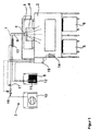
- FIG. 1 the basic structure of an ice machine 1, an ice bin 2 and a device 3 for disinfecting the ice machine 1 and the ice bin 2 is shown.
- the ice cream machine 1 is a flake ice machine in which a rotating freezing roller dips into a pan, which is partially filled with water.
- the ice layer forming on the surface of the freezing roller is continuously peeled off with the aid of a scraper.
- the freezing roller, the tub and the scraper are located in the housing of the ice maker 1 and are not visible in the drawing.
- the flake ice detached from the surface of the freezing roll falls through an ice chute 4 serving as an ice chute into the ice silo 2 and is fed there to the two ice transport carriages 5.
- the device 3 for disinfecting consists essentially of an atomizing nozzle 6, a pressure line 7 for supplying compressed air, a reservoir 8 with hydrogen peroxide and a supply line 9, which connects the reservoir 8 with the atomizing nozzle 6.
- the pressure line 7 also opens into the atomizing nozzle 6.
- the compressed air is generated by means of an air compressor 10.
- the serving as a disinfectant hydrogen peroxide is removed by means of a suction lance 11 from the reservoir 8 and fed to the supply line 9.
- a float switch 12 determines if enough hydrogen peroxide is present in the reservoir. If the level falls below a predetermined limit, the user is notified of the defect.
- a water heater 13 is arranged as a heater. It heats the atomizing nozzle supplied hydrogen peroxide so that it is introduced at a temperature of about 40 to 50 degrees Celsius in the ice chute 4.
- the atomizing nozzle is arranged in the upper region of the ice chute 4 and oriented downwards.
- the atomized in the atomizing nozzle 6 with the compressed air and finely atomized hydrogen peroxide is introduced into the ice chute 4 and spreads due to its comparable with a gas physical properties throughout the volume of the ice chute 4 and the ice bin 2.
- an operating device 14 for the device for disinfecting is arranged on the housing of the ice bin 2.
- the operating device 14 is connected to a control device 15. This actuates a solenoid valve 16 and a pressure switch 17 on the pressure line 7 when the process of disinfecting is started. Further, the suction lance 11 is activated to suck hydrogen peroxide from the reservoir 8. At the request of the user, the water heater 13 is turned on to heat the hydrogen peroxide.
- the controller 15 is also connected to the ice maker 1. The connection of the control device 15 to the various components of the device 3 for disinfecting and to the ice machine is in FIG. 1 represented by dashed lines.
- FIGS. 2 to 9 show various embodiments of ice machines, ice silos and ice shafts, which with a device 3 for disinfecting according to FIG. 1 are equipped.
- a device 3 for disinfecting according to FIG. 1 are equipped.
- the first embodiment according to the FIGS. 2 to 5 there is an ice maker 99 on the Housing of an ice bin 20.
- the ice produced by the ice machines 19 is fed to the ice silo.
- the ice enters an ice transport car 22.
- the device for disinfecting is integrated into the housing of the ice bin 20.
- the device is in the FIGS. 2 to 5 not visible.
- the atomizing nozzles are installed in the ice chute 21, the ice bin 20 and the ice cream maker 19 in such a way that the disinfectant expanded out of the atomizing nozzle can be distributed inside these appliances.
- FIG. 6 shows a second embodiment of an ice cream maker 23 with an ice bin 24, an ice chute 25 and an ice cream cart 26.
- the ice machine 23 is not arranged on the housing of the ice bin 24 but on a wall bracket 27.
- the elements of a device for disinfecting are in FIG. 6 Although not recognizable, however, they are according to the structure according to FIG. 1 integrated into the components of the ice bin 24 and the ice chute 25.
- FIG. 7 shows a third embodiment of an ice cream machine 28 with an ice chute 29 and two ice transport car 30.
- the ice cream machine 28 is disposed on a false ceiling 31.
- the ice chute 29 is a so-called trouser shaft, with a flap control with light barrier. This ensures that the ice made with the ice cream machine 28 is distributed to the two ice cream trucks.
- FIGS. 8 and 9 a fourth embodiment with an ice maker 32, an ice bin 33, an ice chute 34 and two ice transport car 35 is shown.
- the ice bin 33 is equipped with a flap 36 so that it can be opened for inspection and maintenance.
Abstract
Description
Die Erfindung geht aus von einer Vorrichtung und einem Verfahren zum Desinfizieren von Eismaschinen, Eissilos und/ oder Eiskanälen zum Transportieren von Eis sowie von Eismaschinen und Eissilos, welche mit Vorrichtungen zum Desinfizieren ausgestattet sind.The invention is based on an apparatus and a method for disinfecting ice machines, ice silos and / or ice channels for transporting ice as well as ice machines and ice silos, which are equipped with devices for disinfecting.
Eismaschinen dienen dazu, aus beliebigen Flüssigkeiten Eis herzustellen. Das Eis kann dabei unterschiedliche Formen aufweisen wie beispielsweise dünne Blättchen, Würfel, Flocken, Flüssigeis oder ein Granulat aus Körnern. Als Flüssigkeit zur Herstellung des Eises wird häufig Wasser eingesetzt. Das aus Wasser produzierte Eis wird zur Herstellung von Nahrungsmitteln und zur Frischhaltung von Nahrungsmitteln beim Transport und bei der Lagerung eingesetzt. Auf diese Weise können beispielsweise Fleisch, Fisch oder Meerestiere gelagert und transportiert werden, ohne dass deren Qualität leidet. Eis in Form von dünnen Blättchen, welches auch als Scherbeneis bezeichnet wird, wird bei der Herstellung von Wurst eingesetzt. Neben Wasser können auch andere Flüssigkeiten wie beispielsweise Säfte, Soßen, Ei, Milch und Milchprodukte zu Eis verarbeitet werden. Das mittels einer Eismaschine hergestellte Eis wird bei größeren Anlagen in sogenannten Eissilos gesammelt, bevor es der weiteren Bearbeitung oder dem Einsatzort zugeführt wird. Die Eissilos sind meist mit großen Behältern ausgestattet, in welche das durch die Eismaschine produzierte Eis über Kanäle, welche auch als Eisschächte bezeichnet werden, geleitet wird. Die Eissilos sind häufig wärmegedämmt, um zu verhindern, dass das Eis während der Lagerung schmilzt.Ice machines are used to make ice from any liquid. The ice may have different shapes such as thin leaves, cubes, flakes, liquid ice or granules of grains. Water is often used as the liquid for making the ice. The ice produced from water is used to produce food and keep food fresh during transport and storage. In this way, for example, meat, fish or marine animals can be stored and transported without their quality suffers. Ice in the form of thin leaflets, which is also referred to as flake ice, is used in the production of sausage. In addition to water, other liquids such as juices, sauces, egg, and milk can Dairy products are processed into ice cream. The ice produced by means of an ice cream machine is collected in larger systems in so-called ice silos before it is fed to the further processing or the place of use. The ice silos are usually equipped with large containers, in which the ice produced by the ice machine via channels, which are also referred to as ice shafts, is directed. The ice silos are often thermally insulated to prevent the ice from melting during storage.
Da das Eis für die Herstellung von Nahrungsmitteln eingesetzt wird, werden an die Eismaschine zur Herstellung des Eises und an das Eissilo zum Sammeln und Lagern des Eises besonders hohe Anforderungen hinsichtlich der Hygiene gestellt, Es besteht die Anforderung, sämtliche mit dem Eis in Berührung kommenden Oberflächen von Krankheitserregern, insbesondere Bakterien, Viren, Pilzen und Protozoen zu befreien. Hierzu ist eine Desinfektion der entsprechenden Oberflächen der Eismaschine, des Eissilos und der Kanäle, welche die Eismaschine mit dem Eissilo verbinden, in bestimmten Zeftabständen notwendig.Since the ice is used for the production of food, the ice making machine for making the ice and the ice silo for collecting and storing the ice are subject to particularly stringent hygiene requirements. There is a requirement for all surfaces coming into contact with the ice of pathogens, especially bacteria, viruses, fungi and protozoa. For this purpose, a disinfection of the corresponding surfaces of the ice machine, the ice bin and the channels that connect the ice machine with the ice bin, in certain Zeftabständen necessary.
Aus der
Aus der
Der Erfindung liegt daher die Aufgabe zugrunde, eine Vorrichtung zum Desinfizieren von Eismaschinen, Eissilos und Kanälen zum Transportieren von Eis zur Verfügung zu stellen, die kostengünstig hergestellt werden kann, eine zuverlässige Desinfizierung sämtlicher mit dem Eis in Berührung kommenden Oberflächen ermöglicht, und mit der eine Desinfizierung auch während der Eisproduktion durchgeführt werden kann, insbesondere solange sich Eis oder die, zu Eis zu gefrierende Flüssigkeit in der Eismaschine oder dem Eissilo befinden.The invention is therefore an object of the invention to provide a device for disinfecting ice machines, ice silos and channels for transporting ice available, which can be produced inexpensively, allows reliable disinfection of all coming into contact with the ice surfaces, and with the one Disinfection can also be carried out during ice production, especially as long as ice or to be frozen in ice liquid in the ice machine or the ice bin.
Die Erfindung und ihre VorteileThe invention and its advantages
Die erfindungsgemäße Vorrichtung und das erfindungsgemäße Verfahren zeichnen sich dadurch aus, dass ein Desinfektionsmittel mit einer Zerstäubungseinrichtung in kleine Partikel zerstäubt und mit einem Trägerfluid gemischt wird um ein Trägerfluid-Desinfektionsmittel-Gemisch zu erhalten. Anschließend wird das Trägerftuid-Desinfektionsmittel-Gemisch in die Eismaschine, das Eissilo und/ oder die Eiskanäle zum Transportieren von Eis eingeleitet. Hierzu ist die Eismaschine, das Eissilo oder der Eiskanal mit einem Einlass für das Trägerfluid-Desinfektionsmittel-Gemisch ausgestattet. Handelt es sich bei der Zerstäubungseinrichtung um eine Zerstäubungsdüse, so dient diese nicht nur dem Zerstäuben des Desinfektionsmittels sondern auch dem Mischen von Trägerfluid und zerstäubten Desinfektionsmittel und dem Einleiten des Trägerfluid-Desinfektionsmittel-Gemischs in die Eismaschine, das Eissilo oder den Eiskanal.The device according to the invention and the method according to the invention are distinguished by the fact that a disinfectant is atomized into small particles by means of a sputtering device and mixed with a carrier fluid in order to obtain a carrier fluid-disinfectant mixture. Subsequently, the carrier-disinfectant mixture is introduced into the ice-maker, ice-lolly and / or ice channels for transporting ice. For this purpose, the ice machine, the ice bin or the ice channel is equipped with an inlet for the carrier fluid-disinfectant mixture. When the atomizing device is an atomizing nozzle, it serves not only to atomize the disinfectant but also to mix carrier fluid and atomized disinfectant and to introduce the carrier fluid-disinfectant mixture into the ice machine, the ice silo or the ice channel.
Wird als Trägerfluid Luft verwendet, so bildet sich bei diesem Vorgang ein Aerosol aus Luft und Partikeln des Desinfektionsmittels. Ein Aerosol ist ein dynamisches System und unterliegt ständigen Änderungen durch Kondensation von Dämpfen an bereits vorhandenen Partikeln, Verdampfen flüssiger Bestandteile der Partikel, Koagulation kleiner Teilchen zu großen und Abscheidung von Teilchen an umgebenden Gegenständen. Das Trägerfluid-Desinfektionsmittef-Gerrüsch verhält sich wie ein Gas und breitet sich in der gesamten Eismaschine, dem gesamten Eissilo oder dem gesamten Kanal zum Transport des Eises aus. Hierzu genügen eine oder einige wenige Zerstäubungsdüsen. Ferner lagern sich die Partikel des Gemisches an den Krankheitserregern an. Dabei werden die Krankheitserreger aufgrund der Wechselwirkung mit dem Desinfektionsmittel unschädlich gemacht.If air is used as the carrier fluid, this process forms an aerosol of air and particles of the disinfectant. An aerosol is a dynamic system and is subject to constant change due to condensation of vapors on existing particles, evaporation of liquid components of the particles, coagulation of small particles to large and deposition of particles on surrounding objects. The carrier fluid disinfectant composition acts as a gas and spreads throughout the ice machine, the entire ice bin, or the entire channel for transporting the ice. For this purpose, one or a few atomizing nozzles suffice. Furthermore, the particles of the mixture accumulate on the pathogens. The pathogens are rendered harmless due to the interaction with the disinfectant.
Die mit Gasen vergleichbare Eigenschaft von Aerosolen wird durch den kleinen Durchmesser bedingt. Reduziert sich der Durchmesser, so verringern sich das Volumen und die Masse in der dritten Potenz. Die Querschnittsfläche verringert sich dagegen nur um die zweite Potenz. Die SinKgeschwindigkeit der Partikel hängt von ihrer Gravitationskraft und dem Luftwiderstand ab- Während die Gravitationskraft durch die Masse der Partikel bestimmt wird, hängt die Luftreibung von der Querschnittsfläche und der Geschwindigkeit ab. Bei einer Halbierung des Partikeldurchmessers nimmt die Sinkgeschwindigkeit um den Faktor 0,7 ab. Daraus resultiert, dass sich das Trägerfluid-Desinfektionsmittel-Gemisch umso besser in dem zu desinfizierenden Raum verteilt, je kleiner der Durchmesser der Partikel ist. Eine kritische Grenze bildet dabei der Durchmesser von 200µm. Unterhalb dieses Durchmessers verteilen sich die Partikel ähnlich wie ein Gas in dem zu desinfizierenden Volumen. Im Unterschied zu den bekannten Reinigungsvorrichtungen müssen die zu desinfizierenden Teile der Eismaschine oder des Eissilos nicht mehr in den Sprühkegel der Zerstäubungsdüse eingebracht werden. Da sich das Trägerfluid-Desinfektionsmittel-Gemisch vergleichbar mit einem Gas in dem betreffenden Volumen verteilt, genügt ein Einlass oder genügen einige wenige Einlässe um das gesamte Volumen mit dem Gemisch auszufüllen und die in dem Volumen angeordneten Teile zu desinfizieren.The gas-like property of aerosols is due to the small diameter. If the diameter decreases, the volume and the mass decrease in the third power. In contrast, the cross-sectional area only decreases by the second power. The SinK velocity of the particles depends on their gravitational force and air resistance. While the gravitational force is determined by the mass of the particles, the air friction depends on the cross-sectional area and the velocity. If the particle diameter is halved, the rate of descent decreases by a factor of 0.7. As a result, the smaller the diameter of the particles, the better is the carrier fluid-disinfectant mixture distributed in the space to be disinfected. A critical limit is the diameter of 200μm. Below this diameter, the particles are distributed similar to a gas in the volume to be disinfected. In contrast to the known cleaning devices, the parts of the ice machine or the ice bin to be disinfected need no longer be introduced into the spray cone of the atomizing nozzle. Since the carrier fluid-disinfectant mixture spreads comparable to a gas in the volume in question, one inlet or a few inlets suffice to fill the entire volume with the mixture and to disinfect the parts arranged in the volume.
Das Desinfektionsmittel muss der Anforderung genügen, dass es Krankheitserreger abtötet. Werden zusätzlich dazu auch die Dauerformen der Krankheitserreger, wie beispielsweise Sporen, beseitigt, so führt dies zu einer Sterilisation. Bei der Wahl des Desinfektionsmittels muss außerdem das Einsatzgebiet des mit der Eismaschine hergestellten Eises berücksichtigt werden. Da eine Desinfektion auch während des Betriebs des Eismaschine und des Sammelns von Eis in dem Eissilo stattfindet, darf das Desinfektionsmittel die Qualität des Eises nicht nachhaltig beeinflussen.The disinfectant must meet the requirement that it kills pathogens. In addition, if the permanent forms of the pathogens, such as spores, are eliminated, this leads to a sterilization. The choice of disinfectant must also take into account the area of use of the ice produced by the ice machine. Since disinfection also takes place during the operation of the ice maker and the collection of ice in the ice silo, the disinfectant must not have a lasting effect on the quality of the ice.
Um das Einbringen möglichst kleiner Partikeln des Desinfektionsmittels in das Trägerfluid zu begünstigen, wird das Trägerfluid unter Druck an einer Zuführung des Desinfektionsmittels vorbeigeführt. Dabei werden kleine Partikel des Desinfektionsmittels mitgenommen und in dem Trägerfluid in Strömungsrichtung transportiert. Der Druck liegt oberhalb des Atmosphärendrucks und beträgt typischerweise 0,5 bis 5,0 bar. Zum Druckaufbau wird beispielsweise ein Kompressor, eine Gasflasche, eine Pumpe oder eine bauseitige Druckluftanlage verwendet.In order to promote the introduction of the smallest possible particles of the disinfectant in the carrier fluid, the carrier fluid is passed under pressure to a supply of the disinfectant. In this case, small particles of the disinfectant are taken and transported in the carrier fluid in the flow direction. The pressure is above the atmospheric pressure and is typically 0.5 to 5.0 bar. To build up pressure, for example, a compressor, a gas cylinder, a pump or an on-site compressed air system is used.
Als Trägerfluid eignen sich grundsätzlich Gase und Flüssigkeiten. Besonders kostengünstig ist der Einsatz von Luft als Trägerfluid. Darüber hinaus können andere Gase oder Wasserdampf als Trägerfluid eingesetzt werden. Wasserdampf hat den Vorteil, dass er aufgrund seiner höheren Temperatur das Desinfektionsmittel entsprechend erwärmt, was zu einer höheren Effizienz des Desinfektionsmittels beim Abtöten von Krankheitserregern führt. Im Vergleich zu Luft ist jedoch das Zurverfügungstellen von Wasserdampf unter Druck mit etwas größerem Aufwand verbunden.As a carrier fluid are basically gases and liquids. Particularly cost-effective is the use of air as a carrier fluid. In addition, other gases or water vapor can be used as the carrier fluid. Steam has the advantage that it heats the disinfectant accordingly due to its higher temperature, which leads to a higher efficiency of the disinfectant in the killing of pathogens. Compared to air, however, the provision of water vapor under pressure is associated with somewhat greater effort.
Nach einer vorteilhaften Ausgestaltung der Erfindung ist die Zerstäubungseinrichtung eine Zerstäubungsdüse. Diese weist einen Anschluss für die Druckleitung, einen Einlass für das Desinfektionsmittel und eine Düsenöffnung zum Expandieren des Trägerfluid-Desinfektionsmittel-Gemischs in die Eismaschine, das Eissilo oder den Eiskanal auf. Vorteilhafterweise mündet die Druckleitung in einen Strömungskanal. Die Düsenöffnung ist an dem der Druckleitung abgewandten Ende des Strömungskanals angeordnet. Über eine Zuleitung oder eine Dosiereinrichtung ist der Vorratsbehälter des Desinfektionsmittels mit dem Strömungskanal verbunden. Bei Strömen des Trägerfluids in dem Strömungskanal reißt das Trägerfluid Partikel des Desinfektionsmittels mit. In Abhängigkeit von dem Druck des Trägerfluids und der Menge an zur Verfügung gestelltem Desinfektionsmittel stellt sich ein Mischungsverhältnis von Trägerfluid und Desinfektionsmittel ein. Ein zusätzliches Mischen oder Dosieren ist in diesem Fall nicht notwendig.According to an advantageous embodiment of the invention, the atomizing device is a spray nozzle. This has a connection for the pressure line, an inlet for the disinfectant and a nozzle opening for expanding the carrier fluid-disinfectant mixture in the ice machine, the ice bin or the ice channel. Advantageously, the pressure line opens into a flow channel. The nozzle opening is arranged on the end remote from the pressure line of the flow channel. Via a feed line or a metering device of the reservoir of the disinfectant is connected to the flow channel. When the carrier fluid flows in the flow channel, the carrier fluid entrains particles of the disinfectant. Depending on the pressure of the carrier fluid and the amount of disinfectant provided, a mixing ratio of carrier fluid and disinfectant sets. Additional mixing or dosing is not necessary in this case.
Nach einer weiteren vorteilhaften Ausgestaltung der Erfindung ist der Strömungskanal mit einem Hindernis zur Erzeugung von Verwirbelungen ausgestattet. Dabei kann es sich beispielsweise um ein Hindernis handeln, welches in den Strömungskanal quer zur Strömungsrichtung hineinragt. Die laminare Strömung des Trägerfluids wird dadurch in eine turbulente Strömung umgewandelt. Diese begünstigt den Vorgang des Mischens und Zerstäubens von Desinfektionsmittel in dem Trägerfluid.According to a further advantageous embodiment of the invention, the flow channel is equipped with an obstacle for generating turbulence. This may be, for example, an obstacle, which projects into the flow channel transversely to the flow direction. The laminar flow of the carrier fluid is thereby converted into a turbulent flow. This favors the process of mixing and atomizing disinfectant in the carrier fluid.
Nach einer weiteren vorteilhaften Ausgestaltung der Erfindung ist die Zerstäubungseinrichtung ein Kontaktzerstäuber, ein Rieselzerstäuber, ein Scheibenzerstäuber, ein Dampfzerstäuber, ein Ultraschallzerstäuber oder ein Klingenburg-Zerstäuber. Bei einem Kontakt- oder Rieselzerstäuber wird eine poröse Oberfläche mit dem Desinfektionsmittel berieselt. Das Trägerfluid strömt an der porösen Oberfläche vorbei und nimmt kleine Partikel des Desinfektionsmittels mit. Der Vorgang wird durch die Verdunstung des Desinfektionsmittels an der porösen Oberfläche begünstigt. Bei einem Scheibenzerstäuber wird das Desinfektionsmittel auf eine rotierende Scheibe aufgetragen. Aufgrund der Zentrifugalkraft werden kleine Partikel des Desinfektionsmittels als feiner Nebel von der Scheibe nach außen geschleudert und von dem strömenden Trägerfluid mitgenommen. Bei einem Dampfzerstäuber wird flüssiges Desinfektionsmittel so stark erwärmt, dass es in den gasförmigen Zustand übergeht. Hierzu werden auch Elektrodensysteme eingesetzt, die zur Erwärmung des Desinfektionsmittels dessen Leitfähigkeit ausnutzen. Das gasförmige Desinfektionsmittel wird in das strömende Trägerfluid eingeleitet. Bei einem Ultraschallzerstäuber wird eine Membran oder Platte in hochfrequente Schwingungen versetzt. Diese Schwingungen werden auf das flüssige Desinfektionsmittel übertragen. Dadurch werden kleine Partikel aus dem flüssigen Desinfektionsmittel herausgeschlagen, welche durch das strömende Trägerfluid mitgenommen werden. Bei einem Klingenberg-Zerstäuber werden in einem Wirbelgitter stabile Längswirbel erzeugt. In die Zentren der Wirbel wird flüssiges Desinfektionsmittel mit hohem Druck eingedüst, Durch die Wirbel wird das Desinfektionsmittel in kleinste Partikel zerstäubt. Das strömende Trägerfluid nimmt die kleinen Partikel mit.According to a further advantageous embodiment of the invention, the atomizing device is a contact atomizer, a Rieselzerstäuber, a disc atomizer, a steam atomizer, a Ultraschallzerstäuber or a Klingenburg atomizer. In a contact or Rieselzerstäuber a porous surface is sprinkled with the disinfectant. The carrier fluid flows past the porous surface and carries with it small particles of the disinfectant. The process is favored by the evaporation of the disinfectant on the porous surface. In a disc atomizer, the disinfectant is applied to a rotating disc. Due to the centrifugal force small particles of the disinfectant are thrown as a fine mist from the disk to the outside and taken away by the flowing carrier fluid. In a steam atomizer liquid disinfectant is heated so much that it goes into the gaseous state. For this purpose, electrode systems are also used, which exploit its conductivity to heat the disinfectant. The gaseous disinfectant is introduced into the flowing carrier fluid. In a Ultraschallzerstäuber a diaphragm or plate is placed in high-frequency oscillations. These vibrations are transferred to the liquid disinfectant. As a result, small particles are knocked out of the liquid disinfectant, which are entrained by the flowing carrier fluid. In a Klingenberg atomizer stable longitudinal vortices are generated in a vortex grid. In the centers of the vortex liquid disinfectant is injected with high pressure, through the vortex is Disinfect the disinfectant into the smallest particles. The flowing carrier fluid entrains the small particles.
Nach einer weiteren vorteilhaften Ausgestaltung der Erfindung ist die Zerstäubungseinrichtung mit einer Einrichtung zum elektrostatischen Aufladen des zerstäubten Desinfektionsmittels ausgestattet. Ferner werden die desinfizierenden Oberflächen der Eismaschine, des Eissilos oder der Eiskanäle elektrostatisch aufgeladen, so dass die Oberflächen die Partikel des Desinfektionsmittels elektrostatisch anziehen. Dabei ist zu beachten, dass die Partikel positiv und die Oberflächen negativ geladen sind oder umgekehrt.According to a further advantageous embodiment of the invention, the atomizing device is equipped with a device for electrostatically charging the atomized disinfectant. Furthermore, the disinfecting surfaces of the ice machine, the ice bin or the ice channels are electrostatically charged, so that the surfaces attract the particles of the disinfectant electrostatically. It should be noted that the particles are positive and the surfaces are negatively charged or vice versa.
Nach einer weiteren vorteilhaften Ausgestaltung der Erfindung ist der Vorratsbehälter mit Wasserstoffperoxid als Desinfektionsmittel ausgestattet. Wasserstoffperoxid hat den Vorteil, dass es in jedem Verhältnis mit Wasser mischbar ist und bei Raumtemperatur in Wasser und Sauerstoff zerfällt. Es ist ein starkes Oxidationsmittel, eine schwache Säure und wirkt bei vielen Mikroorganismen stark toxisch. Bei einer Konzentration von weniger als 8% stellt das Wasserstoffperoxid keine Gefährdung für die mit dem Desinfektionsmittel in Berührung tretenden Personen dar. Beim Zerfall von Wasserstoffperoxid in Wasser und Sauerstoff tritt die desinfizierende Wirkung ein. Diese Wirkung beruht auf dem beim Zerfall entstehenden reaktiven atomaren Sauerstoff. Dieser führt zu einer oxidativen Beschädigung von Zellbestandteilen der Mikroorganismen, insbesondere durch oxidative Quervemetzung prolinreicher Zellwandproteine und durch Inaktivierung katalytischer Cysteinreste in aktiven Zentren von Enzymen. Dies führt zur Abtötung der Zellen der Mikroorganismen. Krankheitserreger werden daher in zuverlässiger Weise unschädlich gemacht. Dabei wird ausgenutzt, dass sich die Partikel des fein zerstäubten Wasserstoffperoxids an den Krankheitserregern anlagern, wodurch eine Wechselwirkung zwischen den Krankheitserregern und dem Wasserstoffperoxid mit der Folge der Abtötung der Krankheitserreger garantiert ist.According to a further advantageous embodiment of the invention, the reservoir is equipped with hydrogen peroxide as a disinfectant. Hydrogen peroxide has the advantage that it is miscible with water in any ratio and decomposes into water and oxygen at room temperature. It is a strong oxidizer, a weak acid and is highly toxic to many microorganisms. At a concentration of less than 8%, the hydrogen peroxide poses no hazard to the persons in contact with the disinfectant. The decomposition of hydrogen peroxide into water and oxygen causes the disinfecting effect. This effect is due to the reactive atomic oxygen produced during decay. This leads to oxidative damage of cell components of the microorganisms, in particular by oxidative cross-linking of proline-rich cell wall proteins and by inactivating catalytic cysteine residues in active centers of enzymes. This leads to the killing of the cells of the microorganisms. Pathogens are therefore rendered harmless in a reliable manner. It exploits the fact that the particles of the finely atomized hydrogen peroxide attach to the pathogens, whereby an interaction between the pathogens and the hydrogen peroxide is guaranteed with the result of killing the pathogens.
Wasserstoffperoxid zeichnet sich gegenüber anderen Desinfektionsmitteln dadurch aus, dass es in Wasser und Sauerstoff zerfällt und daher bedenkenlos und ohne Einschränkung bei Eismaschinen und Eissilos eingesetzt werden kann, die der Lebensmittelherstellung und der Lebensmittelbearbeitung dienen, Der Desinfektionsvorgang kann daher auch während der Eisproduktion und zu Zeitpunkten stattfinden, zu denen sich Eis und die gefrierende Flüssigkeit in der Eismaschine oder dem Eissilo befinden. Ein zusätzlicher Spülvorgang nach der Desinfektion zum Beseitigen des Desinfektionsmittels aus der Eismaschine und dem Eissilo ist nicht notwendig. Die nach dem Desinfektionsvorgang in der Eismaschine oder dem Eissilo verbleibenden Zerfallsprodukte Sauerstoff und Wasser beeinträchtigen die Qualität des Eises nicht. Das Eis genügt den erhöhten Anforderungen, weiche in der Lebensmittelindustrie gelten.Hydrogen peroxide is distinguished from other disinfectants in that it decomposes into water and oxygen and can therefore be used safely and without restriction in ice machines and ice silos for food production and processing. The disinfection process can therefore also take place during ice production and at times containing ice and the freezing liquid in the ice machine or the ice silo. An additional rinsing after disinfection to remove the disinfectant from the ice machine and the ice bin is not necessary. The decomposition products oxygen and water remaining after the disinfection process in the ice machine or the ice silo do not affect the quality of the ice. The ice meets the increased requirements that apply in the food industry.
Neben Wasserstoffperoxid können alternativ oder kumulativ weitere Desinfektionsmittel verwendet werden. Eine Lösung mit einer geringen Konzentration an Silberpartikeln eignet sich ebenfalls. Zur Anwendung im Bereich der Lebensmittelindustrie ist die Konzentration so gering zu wählen, dass sie sich nicht nachteilig auf die Qualität des Eises auswirkt. Ferner können Alkohole als Desinfektionsmittel eingesetzt werden.In addition to hydrogen peroxide, other disinfectants can alternatively or cumulatively be used. A solution with a low concentration of silver particles is also suitable. For use in the food industry, the concentration should be so low that it does not adversely affect the quality of the ice. Furthermore, alcohols can be used as disinfectants.
Nach einer weiteren vorteilhaften Ausgestaltung der Erfindung ist der Vorratsbehälter für das Desinfektionsmittel mit der Zerstäubungsdüse über eine Desinfektionsmittel-Zuleitung verbunden. Bei dem Vorratsbehälter kann es sich beispielsweise um einen Kanister handeln, aus dem das Desinfektionsmittel über eine Sauglanze entnommen wird. Bei der Desinfektionsmittel-Zuleitung handelt es sich um eine übliche Flüssigkeitsleitung, beispielsweise einen Schlauch oder ein Rohr, die die Sauglanze mit der Zerstäubungsdüse verbindet. Befindet sich dabei der Vorratsbehälter auf demselben Niveau wie die Zerstäubungsdüse, so gelangt das Desinfektionsmittel allein aufgrund seiner Gewichtskraft ohne äußere Hilfsmittel von dem Vorratsbehälter zu der Düse. Durch Veränderung des Niveaus des Vorratsbehälters relativ zur Zerstäubungsdüse, kann die Geschwindigkeit, mit der das Desinfektionsmittel vom Vorratsbehälter zur Zerstäubungsdüse transportiert wird, beeinflusst werden. Dies wiederum hat einen Einfluss auf die Menge an Desinfektionsmittel in dem Trägerfluid-Desinfektionsmittel-Gemisch, das in der Zerstäubungsdüse hergestellt wird.According to a further advantageous embodiment of the invention, the reservoir for the disinfectant is connected to the atomizing nozzle via a disinfectant supply line. The storage container may be, for example, a canister from which the disinfectant is removed via a suction lance. The disinfectant supply line is a common liquid line, for example a hose or a pipe, which connects the suction lance with the atomizing nozzle. If the storage container is at the same level as the atomizing nozzle, the disinfectant alone, due to its weight without external aids, reaches the nozzle from the storage container. By changing the level of the reservoir relative to the atomizing nozzle, the rate at which the disinfectant can be increased From the reservoir to the atomizer is transported, are influenced. This in turn has an impact on the amount of disinfectant in the carrier fluid-disinfectant mixture made in the atomizing nozzle.
Nach einer weiteren vorteilhaften Ausgestaltung der Erfindung ist an der Zerstäubungsdüse oder an der Desinfektionsmittel-Zuleitung eine Heizeinrichtung angeordnet. Dabei kann es sich beispielsweise um einen Durchlauferhitzer handeln. Ferner können die Düse oder die Desinfektionsmittelzuleitung mit einem Heizdraht oder einer Heizmanschette ausgestattet sein. Um zu verhindern, dass das Desinfektionsmittel vor der Zerstäubung erneut abkühlt, ist dafür Sorge zu tragen, dass die Heizeinrichtung möglichst nahe an der Zerstäubungsdüse angeordnet ist. Bei einer Erwärmung des Desinfektionsmittels auf eine Temperatur zwischen 40 und 55 Grad Celcius wird eine deutlich höhere Effizienz des Desinfektionsmittels beim Abtöten von Krankheitserregern erreicht.According to a further advantageous embodiment of the invention, a heating device is arranged on the atomizing nozzle or on the disinfectant supply line. This may be, for example, a water heater. Furthermore, the nozzle or the disinfectant supply line can be equipped with a heating wire or a heating sleeve. To prevent the disinfectant from cooling again before spraying, care must be taken that the heating device is arranged as close as possible to the atomizing nozzle. By heating the disinfectant to a temperature between 40 and 55 degrees Celcius, a significantly higher efficiency of the disinfectant in killing pathogens is achieved.
Nach einer weiteren vorteilhaften Ausgestaltung der Erfindung ist an die Druckleitung zum Zuführen des Trägerfluids eine Heizeinrichtung angeordnet. Diese kann alternativ oder kumulativ zu der Heizeinrichtung an der Desinfektionsmittel-Zuleitung oder der Zerstäubungsdüse vorgesehen sein. Sie führt ebenfalls zu einer Erwärmung des Desinfektionsmittels und damit zu einer Steigerung der Effizienz des Desinfektionsvorgangs.According to a further advantageous embodiment of the invention, a heating device is arranged on the pressure line for supplying the carrier fluid. This may be provided alternatively or cumulatively to the heating device on the disinfectant supply line or the atomizing nozzle. It also leads to a heating of the disinfectant and thus to an increase in the efficiency of the disinfection process.
Nach einer weiteren vorteilhaften Ausgestaltung der Erfindung ist die Vorrichtung mit einer Dosiereinrichtung zum Dosieren des Desinfektionsmittels in das Trägerfluid ausgestattet. Eine derartige Dosiereinrichtung kann beispielsweise mit einem Dosierelement ausgestattet sein, das eine vorgegebene Menge an Desinfektionsmittel aus dem Vorratsbehälter entnimmt und in das unter Druck strömende Trägerfluid einführt. Zu diesem Zweck kann das Dosierelement beispielsweise einen Hohlraum aufweisen, weicher in dem Vorratsbehälter mit flüssigem Desinfektionsmittel gefüllt wird. In bevorzugter Weise weist der Hohlraum einen Einlass und einen Auslass auf. Das Dosierelement wird in dem unter Druck strömenden Trägerfluid derart ausgerichtet, dass der Einlass und der Auslass in Strömungsrichtung ausgerichtet sind. Das strömende Trägerfluid reißt das in dem Hohlraum befindliche Desinfektionsmittel mit.According to a further advantageous embodiment of the invention, the device is equipped with a metering device for metering the disinfectant into the carrier fluid. Such a metering device may for example be equipped with a metering element, which removes a predetermined amount of disinfectant from the reservoir and introduces into the pressurized carrier fluid. For this purpose, the metering element, for example, have a cavity, which is filled in the reservoir with liquid disinfectant. In preferred Way, the cavity has an inlet and an outlet. The metering element is oriented in the pressurized carrier fluid such that the inlet and the outlet are aligned in the flow direction. The flowing carrier fluid entrains the disinfectant in the cavity.
Nach einer weiteren vorteilhaften Ausgestaltung der Erfindung ist die Vorrichtung mit einer Mischeinrichtung zum Mischen des Desinfektionsmittels in dem Trägerfluid ausgestattet. Dabei kann es sich beispielsweise um eine spezielle Mischkammer handeln, die zusätzlich mit Vorrichtungen ausgestattet ist, die eine Verwirbelung des Trägerfluids und damit eine Durchmischung von Trägerfluid und Desinfektionsmittel bewirken.According to a further advantageous embodiment of the invention, the device is equipped with a mixing device for mixing the disinfectant in the carrier fluid. This may be, for example, a special mixing chamber, which is additionally equipped with devices that cause a turbulence of the carrier fluid and thus a mixing of carrier fluid and disinfectant.
Eine erfindungsgemäße Eismaschine oder ein erfindungsgemäßes Eissilo ist derart mit der erfindungsgemäßen Vorrichtung zum Desinfizieren ausgestattet, dass die mindestens eine Zerstäubungseinrichtung in das Gehäuse integriert ist. Der Einlass für das Trägerfluid-Desinfektionsmittel-Gemisch befindet sich vorteilhafter Weise an einem Gehäuseelement, das den Innenraum der Eismaschine, des Eissilos und/ oder der Eiskanäle begrenzt. Damit kann das feinzerstäubte Trägerfluid-Desinfektionsmittel-Gemisch in das Innere der Eismaschine, des Eissilos oder des Eiskanals eingeleitet werden. Die übrigen Teile der Vorrichtung zum Desinfizieren befinden sich außerhalb des zu reinigenden Volumens. Sie sind jedoch vorteilhafterweise in das die Eismaschine, das Eissilo oder den Eiskanal nach außen abgrenzende Gehäuse integriert.An ice machine according to the invention or an ice bin according to the invention is equipped with the device according to the invention for disinfecting such that the at least one atomizing device is integrated into the housing. The inlet for the carrier fluid-disinfectant mixture is advantageously located on a housing element that delimits the interior of the ice machine, the ice bin and / or the ice channels. Thus, the finely atomized carrier fluid-disinfectant mixture can be introduced into the interior of the ice maker, the ice bin or the ice channel. The remaining parts of the device for disinfecting are outside of the volume to be cleaned. However, they are advantageously integrated into the housing defining the ice machine, the ice silo or the ice channel to the outside.
Weitere Vorteile und vorteilhafte Ausgestaltungen der Erfindung sind der nachfolgenden Beschreibung, der Zeichnung und den Ansprüchen zu entnehmen.Further advantages and advantageous embodiments of the invention will become apparent from the following description, the drawings and the claims.
in der Zeichnung ist ein Ausführungsbeispiel einer Vorrichtung zum Desinfizieren eines Eisschachtes und eines Eissilos dargestellt. Ferner zeigt die Zeichnung verschiedene Ausführungs beispiele einer Eismaschine mit Eisschacht und Eissilo, welche mit einer erfindungsgemäßen Vorrichtung zum Desinfizieren ausgestattet sind. Es zeigen:
- Figur 1
- Aufbau einer Vorrichtung zum Desinfizieren eines Eisschachtes und eines Eissilos,
- Figur 2
- erstes Ausführungsbeispiel einer Eismaschine mit Eisschacht und Eissilo in einer perspektivischen Darstellung,
- Figur 3
- Eismaschine mit Eisschacht und Eissilo gemäß
Figur 2 in einer Seitenansicht, - Figur 4
- Eismaschine mit Eisschacht und Eissilo gemäß
Figur 2 in einer Ansicht von vorne, - Figur 5
- Eismaschine mit Eisschacht und Eissilo gemäß
Figur 2 in einer Ansicht von oben, Figur 6- zweites Ausführungsbeispiel einer Eismaschine mit Eisschacht und Eissilo in einer Seitenansicht,
- Figur 7
- drittes Ausführungsbeispiel einer Eismaschine mit Eisschacht in einer Ansicht von vorne
Figur 8- viertes Ausführungsbeispiel einer Eismaschine mit Eisschacht und Eissilo in einer Ansicht von vorne,
- Figur 9
- Eismaschine mit Eisschacht und Eissilo gemäß
Figur 8 in einer Seitenansicht.
- FIG. 1
- Construction of a device for disinfecting an ice chute and an ice bin,
- FIG. 2
- First embodiment of an ice machine with ice chute and ice bin in a perspective view,
- FIG. 3
- Ice machine with ice chute and ice silo according to
FIG. 2 in a side view, - FIG. 4
- Ice machine with ice chute and ice silo according to
FIG. 2 in a view from the front, - FIG. 5
- Ice machine with ice chute and ice silo according to
FIG. 2 in a view from above, - FIG. 6
- second embodiment of an ice machine with ice chute and ice silo in a side view,
- FIG. 7
- third embodiment of an ice maker with ice chute in a view from the front
- FIG. 8
- Fourth embodiment of an ice machine with ice chute and ice silo in a front view,
- FIG. 9
- Ice machine with ice chute and ice silo according to
FIG. 8 in a side view.
In
Die Zerstäubungsdüse ist im oberen Bereich des Eisschachtes 4 angeordnet und nach unten ausgerichtet. Das sich in der Zerstäubungsdüse 6 mit der Druckluft vermischende und fein zerstäubte Wasserstoffperoxid wird in den Eisschacht 4 eingeleitet und breitet sich aufgrund seiner mit einem Gas vergleichbaren pysikalischen Eigenschaften im gesamten Volumen des Eisschachtes 4 und des Eissilos 2 aus.The atomizing nozzle is arranged in the upper region of the ice chute 4 and oriented downwards. The atomized in the
An dem Gehäuse des Eissilos 2 ist eine Bedieneinrichtung 14 für die Vorrichtung zum Desinfizieren angeordnet. An diesem Bedienteil kann der Benutzer entweder den Beginn und das Ende eines Desinfektionsvorgangs manuell vorgeben oder eine automatische Desinfizierung in von ihm gewählten zeitlichen Abständen veranlassen. Die Bedieneinrichtung 14 ist mit einer Steuerungseinrichtung 15 verbunden. Diese betätigt ein Magnetventil 16 und einen Druckschalter 17 an der Druckleitung 7, wenn der Vorgang des Desinfizierens gestartet wird. Ferner wird die Sauglanze 11 aktiviert um Wasserstoffperoxid aus dem Vorratsbehälter 8 anzusaugen. Auf Wunsch des Benutzers wird der Durchlauferhitzer 13 zum Erwärmen des Wasserstoffperoxids eingeschaltet. Die Steuerungseinrichtung 15 ist außerdem mit der Eismaschine 1 verbunden. Die Anbindung der Steuerungseinrichtung 15 an die verschiedenen Komponenten der Vorrichtung 3 zum Desinfizieren und an die Eismaschine ist in
Die
In den
Sämtliche Merkmale der Erfindung können sowohl einzeln als auch in beliebiger Kombination miteinander erfindungswesentlich sein.All features of the invention may be essential to the invention both individually and in any combination with each other.
- 11
- Eismaschineice cream machine
- 22
- Eissiloice silo
- 33
- Vorrichtung zum DesinfizierenDevice for disinfecting
- 44
- EisschachtIce Chute
- 55
- Eistransportwagenice transportation
- 66
- Zerstäubungsdüseatomizing nozzle
- 77
- Druckleitungpressure line
- 88th
- Vorratsbehälterreservoir
- 99
- Zuleitungsupply
- 1010
- DruckluftkompressorAir Compressor
- 1111
- Sauglanzelance
- 1212
- Schwimmerschalterfloat switch
- 1313
- DurchlauferhitzerHeater
- 1414
- Bedieneinrichtungoperating device
- 1515
- Steuerungseinrichtungcontrol device
- 1616
- Magnetventilmagnetic valve
- 1717
- Druckschalterpressure switch
- 1818
- 1919
- Eismaschineice cream machine
- 2020
- Eissiloice silo
- 2121
- EisschachtIce Chute
- 2222
- Eistransportwagenice transportation
- 2323
- Eismaschineice cream machine
- 2424
- Eissiloice silo
- 2525
- EisschachtIce Chute
- 2626
- Eistransportwagenice transportation
- 2727
- Wandkonsolewall bracket
- 2828
- Eismaschineice cream machine
- 2929
- EisschachtIce Chute
- 3030
- Eistransportwagenice transportation
- 3131
- Zwischendeckefalse ceiling
- 3232
- Eismaschineice cream machine
- 3333
- Eissiloice silo
- 3434
- EisschachtIce Chute
- 3535
- Eistransportwagenice transportation
Claims (20)
mit einem Vorratsbehälter (8) zur Aufnahme eines Desinfektionsmittels,
mit einer Druckleitung (7) zum Zuleiten eines Trägerfluids unter Druck,
mit mindestens einer Zersiäubungseinrichtung (6) zum Zerstäuben des Desinfektionsmittels und zur Erzeugung eines Gemischs aus Trägerfluid und Desinfektionsmittel und
mit einem Einlass zum Einleiten des Trägerfluid-Desinfektionsmittel-Gemischs in die Eismaschine (1,19,23,28, 32), das Eissilo (2, 20, 24, 33) oder die Eiskanäle (4, 21, 29, 34).Device for disinfecting ice machines, ice silos and / or channels for transporting ice
with a storage container (8) for receiving a disinfectant,
with a pressure line (7) for supplying a carrier fluid under pressure,
with at least one Zersiäubungseinrichtung (6) for atomizing the disinfectant and for generating a mixture of carrier fluid and disinfectant and
with an inlet for introducing the carrier fluid-disinfectant mixture into the ice machine (1,19,23,28, 32), the ice bin (2, 20, 24, 33) or the ice channels (4, 21, 29, 34).
Applications Claiming Priority (1)
| Application Number | Priority Date | Filing Date | Title |
|---|---|---|---|
| DE102007015584A DE102007015584A1 (en) | 2007-03-29 | 2007-03-29 | Device and method for disinfecting ice machines, ice silos and / or channels for transporting ice |
Publications (2)
| Publication Number | Publication Date |
|---|---|
| EP1975528A2 true EP1975528A2 (en) | 2008-10-01 |
| EP1975528A3 EP1975528A3 (en) | 2011-11-02 |
Family
ID=39591514
Family Applications (1)
| Application Number | Title | Priority Date | Filing Date |
|---|---|---|---|
| EP08004576A Withdrawn EP1975528A3 (en) | 2007-03-29 | 2008-03-12 | Method and device for disinfecting ice machines, ice silos and/or channels for transporting ice |
Country Status (4)
| Country | Link |
|---|---|
| US (1) | US20090000317A1 (en) |
| EP (1) | EP1975528A3 (en) |
| CN (1) | CN101301480A (en) |
| DE (1) | DE102007015584A1 (en) |
Cited By (3)
| Publication number | Priority date | Publication date | Assignee | Title |
|---|---|---|---|---|
| WO2010115407A3 (en) * | 2009-04-09 | 2011-02-24 | Maja-Maschinenfabrik Hermann Schill Gmbh & Co. Kg | Apparatus for producing flake ice and method for cleaning, descaling and/or disinfecting an apparatus for producing flake ice |
| EP2674031A1 (en) * | 2012-05-24 | 2013-12-18 | Andreas Serafeimidis | Method for disinfecting ice making machines |
| ITMI20130737A1 (en) * | 2013-05-07 | 2014-11-08 | Sol Spa | DEVICE FOR SANITIZING OBJECTS |
Families Citing this family (9)
| Publication number | Priority date | Publication date | Assignee | Title |
|---|---|---|---|---|
| WO2012106484A2 (en) * | 2011-02-02 | 2012-08-09 | Robert Amblad | Positive air pressure ice making and dispensing system |
| US9003824B2 (en) | 2011-02-02 | 2015-04-14 | Robert Almblad | Positive air pressure ice making and dispensing system |
| EP2692848B1 (en) * | 2011-03-29 | 2015-03-25 | Panasonic Healthcare Holdings Co., Ltd. | Decontamination solution spray device |
| CN104736002A (en) * | 2012-08-01 | 2015-06-24 | 科尼利斯有限公司 | Ice dispensing and cleaning mechanism and process |
| US10758948B1 (en) * | 2019-04-01 | 2020-09-01 | William Edmund Harris | Apparatus and methods for cleaning and remediating environmental air handling apparatus |
| US9797644B1 (en) * | 2017-03-09 | 2017-10-24 | Taylor Christopher Lowe | Collapsible and expandable ice dispensing tubing apparatus and related devices and methods of use |
| CN112045938B (en) * | 2020-09-01 | 2022-02-25 | 东莞市骅辉包装制品有限公司 | Manufacturing and processing technology of food plastic packaging box |
| IT202000021142A1 (en) * | 2020-09-07 | 2022-03-07 | Ice Cube Impianti S R L | PROCESS FOR THE PRODUCTION OF ICE FOR FOOD USE |
| DE102020132322A1 (en) | 2020-12-04 | 2022-06-09 | Christof Münster | Process and device for disinfecting surfaces, for example a mobile water supply system, and hygiene management system |
Citations (2)
| Publication number | Priority date | Publication date | Assignee | Title |
|---|---|---|---|---|
| DE4108911A1 (en) | 1991-03-19 | 1992-09-24 | Schill Maja Masch | FINE IRON GENERATOR AND METHOD FOR OPERATING IT |
| DE19821284A1 (en) | 1998-05-13 | 1999-11-18 | Maja Maschinenfabrik Herrmann | Machine for making fragmented sheet ice for meat |
Family Cites Families (14)
| Publication number | Priority date | Publication date | Assignee | Title |
|---|---|---|---|---|
| US3841555A (en) * | 1972-08-14 | 1974-10-15 | D Lilja | Spray apparatus and method |
| CA1130588A (en) * | 1980-08-26 | 1982-08-31 | Ronald L. Abbott | Apparatus for producing and dispensing cold products |
| US5289691A (en) * | 1992-12-11 | 1994-03-01 | The Manitowoc Company, Inc. | Self-cleaning self-sterilizing ice making machine |
| US5301516A (en) * | 1993-02-11 | 1994-04-12 | Forrest Poindexter | Potable water collection apparatus |
| US5458851A (en) * | 1993-10-29 | 1995-10-17 | Packaged Ice, Inc. | Automatic ice bagger with self-contained sanitizing system |
| DE9412825U1 (en) * | 1994-08-11 | 1994-10-20 | Muenzer Manfred | Device for producing flake ice |
| AU765398B2 (en) * | 1999-05-26 | 2003-09-18 | Lancer Partnership, Ltd. | A movable ice gate assembly for a beverage dispenser system |
| CA2297002A1 (en) * | 2000-01-26 | 2001-07-26 | Triosyn Corp. | Antimicrobial flash-dry disinfectant aerosol |
| US6532797B1 (en) * | 2000-02-04 | 2003-03-18 | E. I. Du Pont De Nemours And Company | Barrier test apparatus and method |
| JP4526820B2 (en) * | 2001-09-05 | 2010-08-18 | 大日本印刷株式会社 | PET bottle sterilization method and sterilizer |
| AUPR861401A0 (en) * | 2001-11-02 | 2001-11-29 | Ozone Manufacturing Pty Ltd | Ice machine purifier |
| US20050268646A1 (en) * | 2002-08-20 | 2005-12-08 | Yuan James T | Novel biological treating agent |
| DE10346843B4 (en) * | 2002-12-03 | 2018-03-01 | Robert Bosch Gmbh | Device for gasifying a decontamination agent |
| CH696801A5 (en) * | 2002-12-03 | 2007-12-14 | Bosch Gmbh Robert | An apparatus for gasifying a decontaminant. |
-
2007
- 2007-03-29 DE DE102007015584A patent/DE102007015584A1/en not_active Withdrawn
-
2008
- 2008-03-12 EP EP08004576A patent/EP1975528A3/en not_active Withdrawn
- 2008-03-26 CN CNA2008100877516A patent/CN101301480A/en active Pending
- 2008-03-27 US US12/079,549 patent/US20090000317A1/en not_active Abandoned
Patent Citations (2)
| Publication number | Priority date | Publication date | Assignee | Title |
|---|---|---|---|---|
| DE4108911A1 (en) | 1991-03-19 | 1992-09-24 | Schill Maja Masch | FINE IRON GENERATOR AND METHOD FOR OPERATING IT |
| DE19821284A1 (en) | 1998-05-13 | 1999-11-18 | Maja Maschinenfabrik Herrmann | Machine for making fragmented sheet ice for meat |
Cited By (5)
| Publication number | Priority date | Publication date | Assignee | Title |
|---|---|---|---|---|
| WO2010115407A3 (en) * | 2009-04-09 | 2011-02-24 | Maja-Maschinenfabrik Hermann Schill Gmbh & Co. Kg | Apparatus for producing flake ice and method for cleaning, descaling and/or disinfecting an apparatus for producing flake ice |
| CN102369402A (en) * | 2009-04-09 | 2012-03-07 | 玛亚机器制造厂赫尔曼希尔两合公司 | Apparatus for producing flake ice and method for cleaning, descaling and/or disinfecting an apparatus for producing flake ice |
| EP2674031A1 (en) * | 2012-05-24 | 2013-12-18 | Andreas Serafeimidis | Method for disinfecting ice making machines |
| ITMI20130737A1 (en) * | 2013-05-07 | 2014-11-08 | Sol Spa | DEVICE FOR SANITIZING OBJECTS |
| EP2801375A1 (en) * | 2013-05-07 | 2014-11-12 | SOL S.p.A. | Device for sanitizing objects |
Also Published As
| Publication number | Publication date |
|---|---|
| CN101301480A (en) | 2008-11-12 |
| US20090000317A1 (en) | 2009-01-01 |
| EP1975528A3 (en) | 2011-11-02 |
| DE102007015584A1 (en) | 2008-10-02 |
Similar Documents
| Publication | Publication Date | Title |
|---|---|---|
| EP1975528A2 (en) | Method and device for disinfecting ice machines, ice silos and/or channels for transporting ice | |
| DE3434163C2 (en) | Cleaning method and apparatus | |
| DE60120818T2 (en) | Device for the gasification of sterilization liquids | |
| DE602006000542T2 (en) | Nebulizer for a weak acid solution with cleaning function | |
| CH463024A (en) | Method and device for disinfecting equipment and instruments | |
| DE102013213208A1 (en) | Domestic refrigeration appliance with a storage area and a moistening device for adjusting an ambient humidity in the storage area | |
| DE60007611T2 (en) | DRYER WITH MECHANICAL COMPACTION OF THE STEAM, SYSTEM AND METHOD FOR CHEMICAL CLEANING OF THE STEAM | |
| EP1846169A2 (en) | Method for the mixing and spraying of treatment agents and for rapid generation of a persistent aerosol and device for carrying out said method | |
| DE102004029803A1 (en) | Container treatment machine for the sterilization of containers by means of H2O2 | |
| DE3339930A1 (en) | Method and device for sterilization of cup-shaped containers intended for accommodation of dairy products | |
| WO2005018691A1 (en) | Device and method for sterilizing the air conditioning system of a stationary conditioning system of a building | |
| DE546074C (en) | Device for the fermentation of organic substances | |
| DE2410739A1 (en) | METHOD AND DEVICE FOR GENERATING DRY STEAM | |
| EP3401021B1 (en) | Device for air processing | |
| DE10346843B4 (en) | Device for gasifying a decontamination agent | |
| EP1224948A1 (en) | Process for gas humidification/sterilization | |
| DE102020112847A1 (en) | Disinfection device | |
| DE202020107421U1 (en) | Device for atomizing disinfectants | |
| EP0523118B1 (en) | Process, installation and device for enriching ventilation or air-conditioning air with aromatic substances | |
| DE102004007751B4 (en) | Method and device for humidification | |
| EP1792666A2 (en) | Automated cleaning of open containers | |
| EP2934607A1 (en) | Method and device by which aqueous polymer-containing biocides are atomized by means of ultrasound technology into a room | |
| DE102020132322A1 (en) | Process and device for disinfecting surfaces, for example a mobile water supply system, and hygiene management system | |
| DE202020107008U1 (en) | Device for disinfecting surfaces, for example a mobile water supply system, and hygiene management system | |
| DE1792695A1 (en) | Method and device for treating substances present in powder form or as granules |
Legal Events
| Date | Code | Title | Description |
|---|---|---|---|
| PUAI | Public reference made under article 153(3) epc to a published international application that has entered the european phase |
Free format text: ORIGINAL CODE: 0009012 |
|
| AK | Designated contracting states |
Kind code of ref document: A2 Designated state(s): AT BE BG CH CY CZ DE DK EE ES FI FR GB GR HR HU IE IS IT LI LT LU LV MC MT NL NO PL PT RO SE SI SK TR |
|
| AX | Request for extension of the european patent |
Extension state: AL BA MK RS |
|
| PUAL | Search report despatched |
Free format text: ORIGINAL CODE: 0009013 |
|
| AK | Designated contracting states |
Kind code of ref document: A3 Designated state(s): AT BE BG CH CY CZ DE DK EE ES FI FR GB GR HR HU IE IS IT LI LT LU LV MC MT NL NO PL PT RO SE SI SK TR |
|
| AX | Request for extension of the european patent |
Extension state: AL BA MK RS |
|
| RIC1 | Information provided on ipc code assigned before grant |
Ipc: A61L 2/18 20060101ALI20110926BHEP Ipc: A61L 2/22 20060101ALI20110926BHEP Ipc: F28G 9/00 20060101ALI20110926BHEP Ipc: F25C 1/00 20060101AFI20110926BHEP |
|
| AKY | No designation fees paid | ||
| REG | Reference to a national code |
Ref country code: DE Ref legal event code: R108 |
|
| REG | Reference to a national code |
Ref country code: DE Ref legal event code: R108 Effective date: 20120711 |
|
| STAA | Information on the status of an ep patent application or granted ep patent |
Free format text: STATUS: THE APPLICATION IS DEEMED TO BE WITHDRAWN |
|
| 18D | Application deemed to be withdrawn |
Effective date: 20120503 |