EP1975288A2 - Spinning machine - Google Patents
Spinning machine Download PDFInfo
- Publication number
- EP1975288A2 EP1975288A2 EP08001865A EP08001865A EP1975288A2 EP 1975288 A2 EP1975288 A2 EP 1975288A2 EP 08001865 A EP08001865 A EP 08001865A EP 08001865 A EP08001865 A EP 08001865A EP 1975288 A2 EP1975288 A2 EP 1975288A2
- Authority
- EP
- European Patent Office
- Prior art keywords
- spinning
- spinning machine
- rollers
- traversing
- fiber material
- Prior art date
- Legal status (The legal status is an assumption and is not a legal conclusion. Google has not performed a legal analysis and makes no representation as to the accuracy of the status listed.)
- Granted
Links
- 238000009987 spinning Methods 0.000 title claims abstract description 54
- 239000000463 material Substances 0.000 claims abstract description 16
- 239000002657 fibrous material Substances 0.000 claims description 25
- 238000011144 upstream manufacturing Methods 0.000 claims description 4
- 239000000725 suspension Substances 0.000 abstract 1
- 239000004753 textile Substances 0.000 description 3
- 239000000835 fiber Substances 0.000 description 2
- 238000003860 storage Methods 0.000 description 2
- 230000002411 adverse Effects 0.000 description 1
- 230000015572 biosynthetic process Effects 0.000 description 1
- 235000013351 cheese Nutrition 0.000 description 1
- 230000001419 dependent effect Effects 0.000 description 1
- 229920006240 drawn fiber Polymers 0.000 description 1
- 239000000428 dust Substances 0.000 description 1
- 230000000694 effects Effects 0.000 description 1
- 238000004519 manufacturing process Methods 0.000 description 1
- 238000000034 method Methods 0.000 description 1
- 230000000149 penetrating effect Effects 0.000 description 1
- 238000007378 ring spinning Methods 0.000 description 1
Images


Classifications
-
- D—TEXTILES; PAPER
- D01—NATURAL OR MAN-MADE THREADS OR FIBRES; SPINNING
- D01H—SPINNING OR TWISTING
- D01H5/00—Drafting machines or arrangements ; Threading of roving into drafting machine
- D01H5/18—Drafting machines or arrangements without fallers or like pinned bars
-
- D—TEXTILES; PAPER
- D01—NATURAL OR MAN-MADE THREADS OR FIBRES; SPINNING
- D01H—SPINNING OR TWISTING
- D01H13/00—Other common constructional features, details or accessories
- D01H13/04—Guides for slivers, rovings, or yarns; Smoothing dies
- D01H13/06—Traversing arrangements
-
- D—TEXTILES; PAPER
- D01—NATURAL OR MAN-MADE THREADS OR FIBRES; SPINNING
- D01H—SPINNING OR TWISTING
- D01H5/00—Drafting machines or arrangements ; Threading of roving into drafting machine
- D01H5/18—Drafting machines or arrangements without fallers or like pinned bars
- D01H5/26—Drafting machines or arrangements without fallers or like pinned bars in which fibres are controlled by one or more endless aprons
-
- D—TEXTILES; PAPER
- D01—NATURAL OR MAN-MADE THREADS OR FIBRES; SPINNING
- D01H—SPINNING OR TWISTING
- D01H5/00—Drafting machines or arrangements ; Threading of roving into drafting machine
- D01H5/18—Drafting machines or arrangements without fallers or like pinned bars
- D01H5/56—Supports for drafting elements
-
- D—TEXTILES; PAPER
- D01—NATURAL OR MAN-MADE THREADS OR FIBRES; SPINNING
- D01H—SPINNING OR TWISTING
- D01H5/00—Drafting machines or arrangements ; Threading of roving into drafting machine
- D01H5/18—Drafting machines or arrangements without fallers or like pinned bars
- D01H5/58—Arrangements for traversing drafting elements
Definitions
- the invention relates to a spinning machine according to the preamble of claim 1.
- the DE 101 33 604 A1 describes a device for reciprocating Lunten discussingn, in which the Luntenrise be controlled so that the residence time of the Luntenraising is made uniform over the width of the rolls.
- a disadvantage of the aforementioned prior art is that despite the traversing the service life of the drafting top rollers are relatively short, especially in air spinning machines, usual service lives are in the range of a few days, so that frequent regrinding or frequent replacement of the drafting top rollers is required. Furthermore, it requires in the apparatus for traversing a complex storage of the spinning unit to ensure the exact alignment of the spun assembly with respect to the pair of output rollers. In addition, there is the problem in an interruption of the spinning process and an adjoining remedy by a movable along the textile machine service car that the traversing can not be stopped during the piecing process, if it is a machine-length drive for the traversing. To circumvent this problem, it requires the use of individual drives for traversing at each job, which is associated with a great deal of technical effort.
- Object of the present invention is to develop a spinning machine such that longer life of the drafting top rollers are possible, the disadvantages of the prior art to be overcome in a simple and cost-effective manner.
- the output top rollers so in relation to the spinning units are arranged so that the flow of material between the roll center and one of the roll edges.
- the running-in of the roll coverings is displaced to an off-center region of the upper rolls or the aprons.
- the unilateral shrinkage makes it possible, by loosening and turning the top rollers, to expose them to the fiber material flow with the undamaged surface. In this way, the service life of the top rollers is doubled before the top rollers must be reground.
- At least the output top rollers are arranged in relation to the spinning unit, that the material flow deviates in each case in the same direction from the roller center.
- the top rollers may be arranged in pairs on a respective common axis, which is easily releasably attached to the pendulum carrier.
- the removable from the pendulum carrier top rollers are used after a simple pivoting movement by 180 ° back into the pendulum carrier, so that their non-run-in surface sections are exposed to the fiber flow.
- the arrangement of the two spinning units in the fiber material flow is such that the distance to the central longitudinal axis of the pendulum carrier or the top roller center is unequal.
- a further embodiment provides that the upper rollers are individually solvable from the common axis. That way you can place the top rollers on the opposite side of the common axis, exposing the non-ground portion of the top roller to the fiber material flow.
- the upper rollers released from the axle can also be reattached on the same side of the axle after being rotated through 180 °. In this way too, it is possible to ensure that the area of the upper roller not exposed to the flow of material is exposed to the material flow.
- the side covers which protect the top rollers against penetrating fiber material or dust, be easily releasably secured to the top rollers.
- the top rollers are designed accordingly, so that after turning the top roller, the cover on the opposite side is repositioned.
- the top rollers can be easily detachably mounted on the pendulum carrier by means of separate axes. This development makes it possible to remove the top rollers together with the axis of the pendulum carrier and arranged to pivot 180 ° on the opposite side.
- the drafting system can be provided with upstream and / or intermediate sliver compressors, which are arranged in the material flow direction in alignment with the spinning unit. These support the eccentric guidance of the material flow between the top rollers to the spinning unit. In this way, it is achieved that the fiber material flow is kept aligned in a line with the spinning unit in order not to influence the spinning quality.
- the compressors limit too large a spread of the supplied fiber material in the drafting system.
- the sliver compressors may be arranged on a traversing device, which is a traversing allows the thread material between the roller center and a roll edge of the top rollers.
- the traversing width is limited to a narrow area between the upper roll center and the upper roll edge, which is predetermined by the eccentric arrangement.
- the effort is limited to the traversing of the interposed sliver compressor.
- the influence of the traversing movement on the aligned guide of the fiber material during feeding to the spinning unit is kept low, so that the spinning units can be fixedly mounted.
- the traversing device does not require any expensive storage of the sliver compressors, since the influence due to deviations in the position of the compressors when feeding the fiber material into the spinning aggregate is negligible.
- FIG. 1 an air spinning machine 1 is shown, by means of which the invention will be explained.
- the invention is equally applicable to all textile machines, which have a spinning unit, which is preceded by a drafting, such as a ring spinning machine.
- Such textile machines usually have a plurality of workstations 2 arranged in a row next to one another and a so-called end frame 13 at at least one end.
- each of the working or spinning stations 2 of such an air-spinning machine 1 has a sliver source, for example a sliver can 3, a drafting device 4, an air-spinning device 5, a yarn withdrawal device 6, a yarn cleaner 7 and a thread-changing device 8.
- the Fadenchangier listening 8 ensures that the manufactured in the air spinning device 5 thread is wound in intersecting layers on a package 9.
- the cheese 9 is usually held in a coil frame and is rotated by a coil drive.
- the spinning units 2 of the air-spinning machine 1 are supplied by an automatically operating operating rotor 10, which, guided on rails 11, 12, is movable along the spinning stations 2.
- the drafting units 4 generally comprise an input roller pair 20, a middle roller pair 21 and a pair of output rollers 23, the roller pairs each consisting of drivable lower rollers 20A, 21A, 23A and upper rollers 20B, 21B, 23B held in a pendulum carrier 17.
- the pendulum support 17 is limited movably mounted on a support rod 30 and can by means of a lever 29 in three possible positions a) "loaded", b) "relieved” and c) "folded” positioned.
- Verzugsriemchen 27 are arranged, which are guided on deflecting rails.
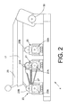
- FIG. 2 illustrates a schematized view from above of the drafting device 4, with the aid of which the arrangement of the components involved in the production process as well as the material flow resulting therefrom are explained.
- the lower rollers 20A, 21A, 23A are covered by the upper rollers 20B, 21B, 23B.
- the fiber material is fed to a drafting unit 4 upstream compressor 33, 33 'and then presented to the input roller pair 20. Between the input roller pair 20 and the middle roller pair 21, a further compressor 34, 34 'is provided.
- the air spinning device 5 connects.
- the fiber material flow is in Fig. 3 as dashed line F indicated. It can clearly be seen here that the fiber material flow F extends between the roller center of the top rollers 20B, 21B, 23B, 20B ', 21B', 23B 'and one of the top roller edges.
- the adjacent air spinning devices 5, 5 ' have a pitch corresponding to the pitch of the drafting device 4 to each other.
- the arrangement of the air spinning devices 5, 5 ' is selected such that the distance between the one air spinning device 5 to the central longitudinal axis M of the pendulum carrier 17 is greater than the distance of the adjacent air spinning device 5'.
- the compressors 33, 33 ', 34, 34' are arranged in order to achieve an aligned material flow F through the drafting device 4 towards the air-spinning devices 5, 5 '.
- top rollers 20B, 21B, 23B and 20B ', 21B', 23B ' has the greatest effect on the top rollers 23B, 23B' of the pair of output rollers 23. That by the delay Fiber material reduced to almost thread diameter creates a groove of appropriate width on top rollers 23B, 23B '. Since the wear due to the eccentric fiber material guide only in the edge regions of the upper rollers 23 B, 23 B 'occurs, interconnected by one axis 14 upper rollers 23 B, 23 B' can be taken out of the shuttle carrier 17 together, and rotated by 180 ° are used again ,
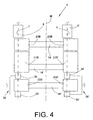
- Fig. 4 represents a further embodiment in which the compressors 33, 33 ', 34, 34' on a traversing device 36, 36 'are arranged.
- the traversing device 36, 36 ' serves to slightly change the compressors 33, 33', 34, 34 'and thus the fiber material between the roller pairs 20, 21, 23 in the region between the roller center and a roller edge.
- the traversing device 36, 36 ' may be connected, for example, to a machine-length eccentric shaft which ensures uniform traversing of the compressors 33, 33', 34, 34 'transversely to the fiber material flow.
- the traversing width is chosen so narrow that the deviation from the aligned feeding of the fiber material into the respective air spinning device 5, 5 'is so slight that the spinning process is not adversely affected.
- the traversing width is less than half the roll width, but preferably less than 10 mm. The resulting deviation in the introduction of the drawn fiber material into the air spinning device 5, 5 'is in the range of less than tenths of a millimeter.
- top rollers 20B, 21B, 23B, 20B ', 21B', 23B ' are detachable from their respective axles 14, 14', 14 "in order to return them on the opposite side réellestecken on the respective axis 14, 14 ', 14' '.
- each upper roller 20B, 21B, 23B, 20B ', 21B', 23B ' is mounted on a separate axle 15, as in FIG Fig. 5 shown schematically.
- both the top rollers of the axes 15 can be solvable or the top rollers 20B, 21B, 23B, 20B ', 21B', 23B 'are released together with their respective axis 15 of the pendulum carrier 17 and on the opposite side to the Axles 15 and arranged on the pendulum carrier 17.
- This arrangement also permits at least the output top rollers 23B, 23B 'to be arranged in relation to the spinning units 5 in such a way that the material flow direction F is guided between the roller center and one of the roller edges.
- At least the output top rollers 23B, 23B ' are arranged in relation to the spinning units 5 such that the material flow F deviates in each case in the same direction from the roller center. This ensures that, after release from the pendulum carrier 17 and the rotation of the upper rollers 20B, 21B, 23B, 20B ', 21B', 23B 'or the axes 14, 14', 14 '', 15 together with the upper rollers 20B located thereon, 21B, 23B, 20B ', 21B', 23B 'always the off-center portions of the top rollers 20B, 21B, 23B, 20B', 21B ', 23B' are exposed to the material flow F, which have not previously been in contact therewith, and thus were also exposed to wear.
Landscapes
- Engineering & Computer Science (AREA)
- Mechanical Engineering (AREA)
- Textile Engineering (AREA)
- Spinning Or Twisting Of Yarns (AREA)
Abstract
Description
Die Erfindung betrifft eine Spinnmaschine gemäß dem Oberbegriff des Anspruches 1.The invention relates to a spinning machine according to the preamble of claim 1.
Bei der Verstreckung von Fasermaterial durch ein Streckwerk, das einem Spinnaggregat Fasermaterial mit einem gewünschten Verzug zuführt, treten an den Walzen sowie den Riemchen des Streckwerkes Verschleißerscheinungen auf, die den Tausch der Riemchen, der Oberwalzenbezüge oder das Nachschleifen insbesondere der Oberwalzen erforderlich werden lassen, das nur begrenzt wiederholbar ist.In the stretching of fiber material by a drafting system, which supplies a spinning unit fiber material with a desired delay, occur on the rollers and the straps of the drafting wear, which will require the replacement of the straps, the Oberwalzenbezüge or re-grinding, in particular the top rollers, the is limited repeatable.
Um die Standzeiten der dem Verschleiß ausgesetzten Teile des Streckwerkes zu erhöhen, ist im Stand der Technik ein Ansatz vorherrschend, wonach das Fasermaterial zur Vermeidung eines ungleichmäßigen Verschleißes der Walzen während der Hindurchführung durch das Streckwerk changiert wird. Dadurch wird die Ausbildung von Rillen durch das Einlaufen in die Walzenbeläge auf Grund des Transports und der Verstreckung des Fasermaterials vermieden, da sich der Verschleiß weitgehend über die Oberfläche der Oberwalzen oder Riemchen vergleichmäßigt. Eine derartige Changierung ist beispielsweise aus der
Die
Nachteilig am vorgenannten Stand der Technik ist, dass trotz der Changierung die Standzeiten der Streckwerksoberwalzen insbesondere bei Luftspinnmaschinen vergleichsweise kurz sind, übliche Standzeiten liegen im Bereich von wenigen Tagen, so dass ein häufiges Nachschleifen beziehungsweise ein häufiger Austausch der Streckwerksoberwalzen erforderlich wird. Des Weiteren bedarf es bei der Vorrichtung zur Changierung einer aufwendigen Lagerung des Spinnaggregates, um die exakt fluchtende Ausrichtung des Spinnaggregates gegenüber dem Ausgangswalzenpaar zu gewährleisten. Zudem besteht bei einer Unterbrechung des Spinnvorganges und einer sich daran anschließenden Behebung durch einen entlang der Textilmaschine verfahrbaren Servicewagen das Problem, dass die Changierung während des Anspinnvorganges nicht stillgesetzt werden kann, sofern es sich um einen maschinenlangen Antrieb für die Changierung handelt. Um diese Problematik zu umgehen, bedarf es der Verwendung von Einzelantrieben für die Changierung an jeder Arbeitsstelle, was mit einem großen technischen Aufwand verbunden ist.A disadvantage of the aforementioned prior art is that despite the traversing the service life of the drafting top rollers are relatively short, especially in air spinning machines, usual service lives are in the range of a few days, so that frequent regrinding or frequent replacement of the drafting top rollers is required. Furthermore, it requires in the apparatus for traversing a complex storage of the spinning unit to ensure the exact alignment of the spun assembly with respect to the pair of output rollers. In addition, there is the problem in an interruption of the spinning process and an adjoining remedy by a movable along the textile machine service car that the traversing can not be stopped during the piecing process, if it is a machine-length drive for the traversing. To circumvent this problem, it requires the use of individual drives for traversing at each job, which is associated with a great deal of technical effort.
Aufgabe der vorliegenden Erfindung ist es, eine Spinnmaschine derart weiterzubilden, dass längere Standzeiten der Streckwerksoberwalzen möglich sind, wobei die Nachteile des Standes der Technik auf einfache und kostengünstige Weise überwunden werden sollen.Object of the present invention is to develop a spinning machine such that longer life of the drafting top rollers are possible, the disadvantages of the prior art to be overcome in a simple and cost-effective manner.
Dies wird erfindungsgemäß durch die kennzeichnenden Merkmale des Anspruches 1 erreicht.This is inventively achieved by the characterizing features of claim 1.
Vorteilhafte Ausführungsformen der Erfindung sind Gegenstand der Unteransprüche.Advantageous embodiments of the invention are the subject of the dependent claims.
Gemäß Anspruch 1 wird vorgeschlagen, dass zumindest die Ausgangsoberwalzen so in Relation zu den Spinnaggregaten angeordnet sind, dass der Materialfluss zwischen der Walzenmitte und einem der Walzenränder verläuft. Dadurch wird das Einlaufen der Walzenbeläge auf einen außermittigen Bereich der Oberwalzen beziehungsweise der Riemchen verlagert. Das einseitige Einlaufen gestattet es, durch Lösen und Umdrehen der Oberwalzen diese dann dem Fasermaterialfluss mit der unbeschädigten Oberfläche auszusetzen. Auf diese Weise wird die Standzeit der Oberwalzen verdoppelt, bevor die Oberwalzen nachgeschliffen werden müssen. Gegenüber dem Stand der Technik kann auf eine zusätzliche Vorrichtung oder einen zusätzlicher Antrieb, der die Changierung zumindest des Fasermateriales gemäß dem Stand der Technik bewirkt, verzichtet werden. Ebenso entfallen dabei zusätzliche Hilfsmittel, die den Lauf des aus dem Streckwerk austretenden Fasermateriales bezüglich des Spinnaggregates korrigieren, um ein fluchtendes Einlaufen in dieses zu ermöglichen.According to claim 1 it is proposed that at least the output top rollers so in relation to the spinning units are arranged so that the flow of material between the roll center and one of the roll edges. As a result, the running-in of the roll coverings is displaced to an off-center region of the upper rolls or the aprons. The unilateral shrinkage makes it possible, by loosening and turning the top rollers, to expose them to the fiber material flow with the undamaged surface. In this way, the service life of the top rollers is doubled before the top rollers must be reground. Compared to the state of the art, it is possible to dispense with an additional device or an additional drive which causes the traversing of at least the fiber material according to the prior art. Likewise, this eliminates additional aids that correct the running of the exiting the drafting fiber material with respect to the spinning unit to allow an aligned entry into this.
Dabei ist vorgesehen, dass mindestens die Ausgangsoberwalzen so in Relation zu dem Spinnaggregat angeordnet sind, dass der Materialfluss jeweils in der gleichen Richtung von der Walzenmitte abweicht.It is provided that at least the output top rollers are arranged in relation to the spinning unit, that the material flow deviates in each case in the same direction from the roller center.
Vorzugsweise können die Oberwalzen paarweise an einer jeweils gemeinsamen Achse angeordnet sein, die leicht lösbar am Pendelträger anbracht ist. Die aus dem Pendelträger herausnehmbaren Oberwalzen werden nach einer einfachen Schwenkbewegung um 180° wieder in den Pendelträger eingesetzt, so dass ihre nicht eingelaufenen Oberflächenabschnitte dem Faserfluss ausgesetzt sind. Somit ist die Anordnung der beiden Spinnaggregate im Fasermaterialfluss derart, dass der Abstand zur Mittellängsachse des Pendelträgers beziehungsweise zur Oberwalzenmitte ungleich ist.Preferably, the top rollers may be arranged in pairs on a respective common axis, which is easily releasably attached to the pendulum carrier. The removable from the pendulum carrier top rollers are used after a simple pivoting movement by 180 ° back into the pendulum carrier, so that their non-run-in surface sections are exposed to the fiber flow. Thus, the arrangement of the two spinning units in the fiber material flow is such that the distance to the central longitudinal axis of the pendulum carrier or the top roller center is unequal.
Eine Weiterbildung sieht vor, dass die Oberwalzen einzeln von der gemeinsamen Achse lösbar sind. Auf diese Weise lassen sich die Oberwalzen auf der gegenüberliegenden Seite der gemeinsamen Achse anordnen, wodurch der nicht eingeschliffene Bereich der Oberwalze dem Fasermaterialfluss ausgesetzt wird. Alternativ können die von der Achse gelösten Oberwalzen auch auf der gleichen Seite der Achse wieder aufgesteckt werden, nachdem sie um 180° gedreht wurden. Auch auf diese Weise lässt sich erreichen, dass der bis dahin dem Materialfluss nicht ausgesetzte Bereich der Oberwalze dem Materialfluss ausgesetzt wird. Hierzu können die seitlichen Abdeckungen, die die Oberwalzen vor eindringendem Fasermaterial oder Staub schützen, leicht lösbar an den Oberwalzen befestigt sein. Die Oberwalzen sind hierfür entsprechend ausgebildet, so dass nach dem Drehen der Oberwalze die Abdeckung auf der gegenüberliegenden Seite wieder aufsteckbar ist.A further embodiment provides that the upper rollers are individually solvable from the common axis. That way you can place the top rollers on the opposite side of the common axis, exposing the non-ground portion of the top roller to the fiber material flow. Alternatively, the upper rollers released from the axle can also be reattached on the same side of the axle after being rotated through 180 °. In this way too, it is possible to ensure that the area of the upper roller not exposed to the flow of material is exposed to the material flow. For this purpose, the side covers, which protect the top rollers against penetrating fiber material or dust, be easily releasably secured to the top rollers. The top rollers are designed accordingly, so that after turning the top roller, the cover on the opposite side is repositioned.
Alternativ können die Oberwalzen mittels separater Achsen leicht lösbar am Pendelträger gelagert sein. Diese Weiterbildung ermöglicht es, die Oberwalzen mitsamt der Achse aus dem Pendelträger zu entnehmen und um 180° geschwenkt auf der gegenüberliegenden Seite anzuordnen.Alternatively, the top rollers can be easily detachably mounted on the pendulum carrier by means of separate axes. This development makes it possible to remove the top rollers together with the axis of the pendulum carrier and arranged to pivot 180 ° on the opposite side.
In bevorzugter Weiterbildung können an der Arbeitsstelle dem Streckwerk vor- und/oder zwischengeschaltete Faserbandverdichter vorgesehen sein, die in Materialflussrichtung fluchtend zum Spinnaggregat angeordnet sind. Diese unterstützen die exzentrische Führung des Materialflusses zwischen den Oberwalzen hin zum Spinnaggregat. Auf diese Weise wird erreicht, dass der Fasermaterialfluss in einer Linie mit dem Spinnaggregat fluchtend gehalten wird, um die Spinnqualität nicht zu beeinflussen. Zudem begrenzen die Verdichter eine zu große Ausbreitung des zugeführten Fasermateriales im Streckwerk.In a preferred development, the drafting system can be provided with upstream and / or intermediate sliver compressors, which are arranged in the material flow direction in alignment with the spinning unit. These support the eccentric guidance of the material flow between the top rollers to the spinning unit. In this way, it is achieved that the fiber material flow is kept aligned in a line with the spinning unit in order not to influence the spinning quality. In addition, the compressors limit too large a spread of the supplied fiber material in the drafting system.
Gemäß einer Weiterbildung können die Faserbandverdichter auf einer Changiereinrichtung angeordnet sein, die eine Changierung des Fadenmateriales zwischen der Walzenmitte und einem Walzenrand der Oberwalzen ermöglicht. Die Changierbreite beschränkt sich dabei auf einen schmalen Bereich zwischen der Oberwalzenmitte und dem Oberwalzenrand, der durch die exzentrische Anordnung vorgegeben ist. Der Aufwand beschränkt sich auf die Changierung der zwischengeschalteten Faserbandverdichter. Der Einfluss der Changierbewegung auf die fluchtende Führung des Fasermateriales beim Zuführen zum Spinnaggregat wird gering gehalten, so dass die Spinnaggregate fix angebracht werden können. Gegenüber dem Stand der Technik bedarf die Changiereinrichtung keiner aufwendigen Lagerung der Faserbandverdichter, da der Einfluss durch Abweichungen in der Position der Verdichter bei der Zuführung des Fasermateriales in das Spinnaggregat vernachlässigbar sind.According to a development, the sliver compressors may be arranged on a traversing device, which is a traversing allows the thread material between the roller center and a roll edge of the top rollers. The traversing width is limited to a narrow area between the upper roll center and the upper roll edge, which is predetermined by the eccentric arrangement. The effort is limited to the traversing of the interposed sliver compressor. The influence of the traversing movement on the aligned guide of the fiber material during feeding to the spinning unit is kept low, so that the spinning units can be fixedly mounted. Compared to the prior art, the traversing device does not require any expensive storage of the sliver compressors, since the influence due to deviations in the position of the compressors when feeding the fiber material into the spinning aggregate is negligible.
Die Erfindung wird nachfolgend anhand eines in den Zeichnungen dargestellten Ausführungsbeispiels näher erläutert.
Es zeigen:
- Fig. 1
- schematisch in Vorderansicht eine Luftspinnmaschine;
- Fig. 2
- ein Streckwerk in Seitenansicht;
- Fig. 3
- eine Ansicht von oben auf ein schematisiert dargestelltes Streckwerk mit an einer gemeinsamen Achse angeordneten Oberwalzen;
- Fig. 4
- eine Ansicht von oben auf ein schematisiert dargestelltes Streckwerk gemäß
Fig. 3 mit einer Changiereinrichtung; - Fig. 5
- eine Ansicht von oben auf ein schematisiert dargestelltes Streckwerk mit an separaten Achsen angeordneten Oberwalzen.
Show it:
- Fig. 1
- schematically in front view of an air-spinning machine;
- Fig. 2
- a drafting system in side view;
- Fig. 3
- a top view of a schematically illustrated drafting with arranged on a common axis top rollers;
- Fig. 4
- a view from above of a schematically illustrated drafting according to
Fig. 3 with a traversing device; - Fig. 5
- a view from above of a schematically illustrated drafting with arranged on separate axes top rollers.
In
Bekanntermaßen verfügt jede der Arbeits- oder Spinnstellen 2 einer solchen Luftspinnmaschine 1 über eine Faserbandquelle, beispielsweise eine Spinnkanne 3, ein Streckwerk 4, eine Luftspinnvorrichtung 5, eine Fadenabzugseinrichtung 6, einen Garnreiniger 7 sowie eine Fadenchangiereinrichtung 8.
Die Fadenchangiereinrichtung 8 sorgt dafür, dass der in der Luftspinnvorrichtung 5 gefertigte Faden in sich kreuzenden Lagen auf eine Auflaufspule 9 gewickelt wird. Die Kreuzspule 9 ist üblicherweise in einem Spulenrahmen gehalten und wird durch einen Spulenantrieb rotiert.As is known, each of the working or spinning
The Fadenchangiereinrichtung 8 ensures that the manufactured in the
Wie in
Wie in
Die benachbarten Luftspinnvorrichtungen 5, 5' weisen einen der Teilung des Streckwerkes 4 entsprechenden Abstand zueinander auf. Dabei ist die Anordnung der Luftspinnvorrichtungen 5, 5' derart gewählt, dass der Abstand der einen Luftspinnvorrichtung 5 zur Mittenlängsachse M des Pendelträgers 17 größer ist, als der Abstand der benachbarten Luftspinnvorrichtung 5'. In gleicher Weise sind die Verdichter 33, 33', 34, 34' angeordnet, um einen fluchtenden Materialfluss F durch das Streckwerk 4 hin zu den Luftspinnvorrichtungen 5, 5' zu erreichen.The adjacent
Der auftretende Verschleiß an den Oberwalzen 20B, 21B, 23B und 20B', 21B', 23B' wirkt sich an den Oberwalzen 23B, 23B' des Ausgangswalzenpaares 23 am stärksten aus. Das durch den Verzug auf nahezu Fadendurchmesser reduzierte Fasermaterial erzeugt eine Rille mit entsprechender Breite auf den Oberwalzen 23B, 23B'. Da der Verschleiß auf Grund der exzentrischen Fasermaterialführung lediglich in den Randbereichen der Oberwalzen 23B, 23B' auftritt, können die durch jeweils eine Achse 14 miteinander verbundenen Oberwalzen 23B, 23B' gemeinsam aus dem Pendelträger 17 herausgenommen werden, und um 180° gedreht wieder eingesetzt werden.The occurring wear on the
Es ist auch denkbar, das Streckwerk 4 so auszugestalten, dass die Oberwalzen 20B, 21B, 23B, 20B', 21B', 23B' von ihrer jeweiligen Achse 14, 14', 14'' lösbar sind, um sie auf der gegenüberliegenden Seite wieder auf die jeweilige Achse 14, 14', 14'' aufzustecken.It is also conceivable to design the
Alternativ kann auch eine Lagerung vorgesehen sein, bei welcher jede Oberwalze 20B, 21B, 23B, 20B', 21B', 23B' auf einer separaten Achse 15 gelagert ist, wie in
In allen beschriebenen Ausführungsformen sind zumindest die Ausgangsoberwalzen 23B, 23B' so in Relation zu den Spinnaggregaten 5 angeordnet, dass der Materialfluss F jeweils in der gleichen Richtung von der Walzenmitte abweicht. Dadurch wird sichergestellt, dass nach dem Lösen vom Pendelträger 17 und dem Drehen der Oberwalzen 20B, 21B, 23B, 20B', 21B', 23B' beziehungsweise der Achsen 14, 14',14'', 15 mitsamt den daran befindlichen Oberwalzen 20B, 21B, 23B, 20B', 21B', 23B' stets die außermittigen Bereiche der Oberwalzen 20B, 21B, 23B, 20B', 21B', 23B' dem Materialfluss F ausgesetzt sind, die zuvor mit diesem nicht in Berührung gekommen sind, und somit auch keinem Verschleiß ausgesetzt waren.In all the embodiments described, at least the output
Claims (7)
Applications Claiming Priority (1)
| Application Number | Priority Date | Filing Date | Title |
|---|---|---|---|
| DE102007015694A DE102007015694A1 (en) | 2007-03-31 | 2007-03-31 | spinning machine |
Related Parent Applications (1)
| Application Number | Title | Priority Date | Filing Date |
|---|---|---|---|
| DE102007015694 Previously-Filed-Application | 2008-02-01 |
Publications (3)
| Publication Number | Publication Date |
|---|---|
| EP1975288A2 true EP1975288A2 (en) | 2008-10-01 |
| EP1975288A3 EP1975288A3 (en) | 2009-12-30 |
| EP1975288B1 EP1975288B1 (en) | 2011-04-27 |
Family
ID=39590691
Family Applications (1)
| Application Number | Title | Priority Date | Filing Date |
|---|---|---|---|
| EP20080001865 Active EP1975288B1 (en) | 2007-03-31 | 2008-02-01 | Spinning machine |
Country Status (4)
| Country | Link |
|---|---|
| EP (1) | EP1975288B1 (en) |
| JP (1) | JP5243081B2 (en) |
| CN (1) | CN101275315A (en) |
| DE (2) | DE102007015694A1 (en) |
Cited By (1)
| Publication number | Priority date | Publication date | Assignee | Title |
|---|---|---|---|---|
| EP2752513A4 (en) * | 2011-08-31 | 2015-07-29 | Murata Machinery Ltd | Spinning machine |
Families Citing this family (2)
| Publication number | Priority date | Publication date | Assignee | Title |
|---|---|---|---|---|
| JP2020066820A (en) * | 2018-10-24 | 2020-04-30 | 村田機械株式会社 | Traverse device, draft device and spinning machine |
| DE102019115218A1 (en) * | 2019-06-05 | 2020-12-10 | Maschinenfabrik Rieter Ag | Compaction device for a drafting system of a spinning machine and spinning machine |
Family Cites Families (12)
| Publication number | Priority date | Publication date | Assignee | Title |
|---|---|---|---|---|
| JPS60449B2 (en) * | 1977-03-15 | 1985-01-08 | 東洋紡績株式会社 | Manufacturing method of bundled yarn |
| DE19601466A1 (en) * | 1996-01-17 | 1997-07-24 | Schurr Stahlecker & Grill | Core yarn assembly at a drawing unit |
| JPH11189933A (en) * | 1997-12-24 | 1999-07-13 | Murata Mach Ltd | Drafting apparatus |
| JPH11256438A (en) * | 1998-03-10 | 1999-09-21 | Murata Mach Ltd | Mounting structure of top roller |
| DE29921746U1 (en) * | 1999-12-10 | 2000-03-30 | Zinser Textilmaschinen Gmbh, 73061 Ebersbach | Drafting system for a spinning machine |
| DE10051413A1 (en) * | 2000-09-01 | 2002-03-14 | Rieter Ag Maschf | Unit to condense drawn sliver, at a spinner drawing unit, has rotating and perforated condensing units with inner suction with reciprocating axial movements to prevent wear and scoring |
| DE10133604A1 (en) | 2001-07-13 | 2003-02-06 | Zinser Textilmaschinen Gmbh | Textile machine slubbing guide residence time is uniform over entire guide width |
| DE10258729B4 (en) | 2002-12-06 | 2008-04-03 | Carl Zeiss | Self-focusing glasses and methods for self-focusing glasses |
| DE10258720A1 (en) * | 2002-12-09 | 2004-06-24 | Wilhelm Stahlecker Gmbh | Textile fibre spinning station has a traversing station connected to compressors serving a drafting station and air jet |
| ES1054642Y (en) * | 2003-04-30 | 2003-12-01 | Pinter Sa | "DEVICE FOR THE CONDENSATION OF FIBERS IN SPINDING MACHINES" |
| DE10356430A1 (en) * | 2003-11-27 | 2005-06-23 | Wilhelm Stahlecker Gmbh | Fibrous band compression unit for spinning machine, has one roller of its feed roller pair formed with concave profile |
| ES2215488B1 (en) * | 2004-03-11 | 2005-08-01 | Pinter, S.A. | IMPROVEMENTS IN THE STYLING TRAINS OF SPINNING MACHINES. |
-
2007
- 2007-03-31 DE DE102007015694A patent/DE102007015694A1/en not_active Withdrawn
-
2008
- 2008-02-01 EP EP20080001865 patent/EP1975288B1/en active Active
- 2008-02-01 DE DE200850003330 patent/DE502008003330D1/en active Active
- 2008-03-24 CN CNA2008100856933A patent/CN101275315A/en active Pending
- 2008-03-31 JP JP2008092593A patent/JP5243081B2/en active Active
Non-Patent Citations (1)
| Title |
|---|
| None |
Cited By (1)
| Publication number | Priority date | Publication date | Assignee | Title |
|---|---|---|---|---|
| EP2752513A4 (en) * | 2011-08-31 | 2015-07-29 | Murata Machinery Ltd | Spinning machine |
Also Published As
| Publication number | Publication date |
|---|---|
| DE502008003330D1 (en) | 2011-06-09 |
| CN101275315A (en) | 2008-10-01 |
| JP2008255558A (en) | 2008-10-23 |
| JP5243081B2 (en) | 2013-07-24 |
| DE102007015694A1 (en) | 2008-10-02 |
| EP1975288B1 (en) | 2011-04-27 |
| EP1975288A3 (en) | 2009-12-30 |
Similar Documents
| Publication | Publication Date | Title |
|---|---|---|
| EP1984549B1 (en) | Machine for producing a knitted fabric from fibrous material, in particular a circular knitting machine | |
| EP2865794B1 (en) | Spinning frame | |
| DE19708410B4 (en) | Drafting system for spinning machines with a fiber-bundling zone | |
| DE102007024234A1 (en) | Stretching unit for use with pressure roller aggregate and compressor component for buckling of bunch of fibers that is made of staple fiber, has lower roller, where lower roller assigns two pressure rollers | |
| EP1757719B1 (en) | Drawing frame for a spinning machine | |
| DE3145208C2 (en) | Method and device for reducing the wear and tear on drafting elements of a spinning machine | |
| WO1998039505A2 (en) | Drawing mechanism for spinning frames with a fibre bunching zone and ring-spinning frame equipped therewith | |
| EP1975288B1 (en) | Spinning machine | |
| WO1981003501A1 (en) | Spinning frame,preferably ring continuous spinning frame | |
| EP0679741A1 (en) | Sliver feeding apparatus | |
| EP0165444B1 (en) | Drive for a waxing device and method for driving such a device | |
| EP3124659A2 (en) | Spinning machine, guide rod and strap | |
| EP3321222B1 (en) | Workstation of a textile machine manufacturing cross-wound packages with a mechanical accumulator arranged in the area of the thread traversing triangle | |
| DE3804147A1 (en) | Apparatus for reshaping a large-sized fibrous web, consisting of a mass of textile fibres, into a card sliver of low width, in particular for a rectilinear comber | |
| EP2547812B1 (en) | Drawing frame having a guide table for a guide apron | |
| CH648874A5 (en) | DEVICE FOR PRODUCING EFFECT YARN. | |
| DE19501163C1 (en) | Drawing unit | |
| DE602005006163T2 (en) | Cotton combing machine and the like with improved sliver forming apparatus | |
| EP0099973B1 (en) | Drawing frame for a spinning machine | |
| WO2015177227A1 (en) | Spinning machine having a false twist device | |
| DE10332711B4 (en) | Belt for winding device | |
| EP3159438A1 (en) | Method for exchanging a lower belt of a stretcher of a spinning machine and spinning machine | |
| DE3331518C2 (en) | Tensioning device for a strap | |
| DE19628164B4 (en) | Adjustable fleece guide | |
| DE3319559A1 (en) | STRETCHING DEVICE IN A SPINNING MACHINE |
Legal Events
| Date | Code | Title | Description |
|---|---|---|---|
| PUAI | Public reference made under article 153(3) epc to a published international application that has entered the european phase |
Free format text: ORIGINAL CODE: 0009012 |
|
| AK | Designated contracting states |
Kind code of ref document: A2 Designated state(s): AT BE BG CH CY CZ DE DK EE ES FI FR GB GR HR HU IE IS IT LI LT LU LV MC MT NL NO PL PT RO SE SI SK TR |
|
| AX | Request for extension of the european patent |
Extension state: AL BA MK RS |
|
| PUAL | Search report despatched |
Free format text: ORIGINAL CODE: 0009013 |
|
| AK | Designated contracting states |
Kind code of ref document: A3 Designated state(s): AT BE BG CH CY CZ DE DK EE ES FI FR GB GR HR HU IE IS IT LI LT LU LV MC MT NL NO PL PT RO SE SI SK TR |
|
| AX | Request for extension of the european patent |
Extension state: AL BA MK RS |
|
| RIC1 | Information provided on ipc code assigned before grant |
Ipc: D01H 5/56 20060101ALI20091123BHEP Ipc: D01H 5/26 20060101AFI20080721BHEP Ipc: D01H 13/06 20060101ALI20091123BHEP Ipc: D01H 5/18 20060101ALI20091123BHEP Ipc: D01H 5/58 20060101ALI20091123BHEP |
|
| 17P | Request for examination filed |
Effective date: 20100630 |
|
| 17Q | First examination report despatched |
Effective date: 20100729 |
|
| AKX | Designation fees paid |
Designated state(s): CH DE LI TR |
|
| GRAP | Despatch of communication of intention to grant a patent |
Free format text: ORIGINAL CODE: EPIDOSNIGR1 |
|
| GRAS | Grant fee paid |
Free format text: ORIGINAL CODE: EPIDOSNIGR3 |
|
| GRAA | (expected) grant |
Free format text: ORIGINAL CODE: 0009210 |
|
| AK | Designated contracting states |
Kind code of ref document: B1 Designated state(s): CH DE LI TR |
|
| REG | Reference to a national code |
Ref country code: CH Ref legal event code: EP |
|
| REF | Corresponds to: |
Ref document number: 502008003330 Country of ref document: DE Date of ref document: 20110609 Kind code of ref document: P |
|
| REG | Reference to a national code |
Ref country code: DE Ref legal event code: R096 Ref document number: 502008003330 Country of ref document: DE Effective date: 20110609 |
|
| PLBE | No opposition filed within time limit |
Free format text: ORIGINAL CODE: 0009261 |
|
| STAA | Information on the status of an ep patent application or granted ep patent |
Free format text: STATUS: NO OPPOSITION FILED WITHIN TIME LIMIT |
|
| 26N | No opposition filed |
Effective date: 20120130 |
|
| REG | Reference to a national code |
Ref country code: DE Ref legal event code: R097 Ref document number: 502008003330 Country of ref document: DE Effective date: 20120130 |
|
| REG | Reference to a national code |
Ref country code: DE Ref legal event code: R081 Ref document number: 502008003330 Country of ref document: DE Owner name: SAURER GERMANY GMBH & CO. KG, DE Free format text: FORMER OWNER: OERLIKON TEXTILE GMBH & CO. KG, 42897 REMSCHEID, DE Effective date: 20130918 Ref country code: DE Ref legal event code: R081 Ref document number: 502008003330 Country of ref document: DE Owner name: SAURER SPINNING SOLUTIONS GMBH & CO. KG, DE Free format text: FORMER OWNER: OERLIKON TEXTILE GMBH & CO. KG, 42897 REMSCHEID, DE Effective date: 20130918 |
|
| REG | Reference to a national code |
Ref country code: CH Ref legal event code: NV Representative=s name: SCHMAUDER AND PARTNER AG PATENT- UND MARKENANW, CH Ref country code: CH Ref legal event code: PUE Owner name: SAURER GERMANY GMBH AND CO. KG, DE Free format text: FORMER OWNER: OERLIKON TEXTILE GMBH AND CO. KG, DE |
|
| REG | Reference to a national code |
Ref country code: CH Ref legal event code: PCOW Free format text: NEW ADDRESS: LEVERKUSER STRASSE 65, 42897 REMSCHEID (DE) |
|
| PGFP | Annual fee paid to national office [announced via postgrant information from national office to epo] |
Ref country code: TR Payment date: 20150129 Year of fee payment: 8 |
|
| REG | Reference to a national code |
Ref country code: DE Ref legal event code: R081 Ref document number: 502008003330 Country of ref document: DE Owner name: SAURER INTELLIGENT TECHNOLOGY AG, CH Free format text: FORMER OWNER: SAURER GERMANY GMBH & CO. KG, 42897 REMSCHEID, DE Ref country code: DE Ref legal event code: R081 Ref document number: 502008003330 Country of ref document: DE Owner name: SAURER SPINNING SOLUTIONS GMBH & CO. KG, DE Free format text: FORMER OWNER: SAURER GERMANY GMBH & CO. KG, 42897 REMSCHEID, DE |
|
| REG | Reference to a national code |
Ref country code: DE Ref legal event code: R081 Ref document number: 502008003330 Country of ref document: DE Owner name: SAURER INTELLIGENT TECHNOLOGY AG, CH Free format text: FORMER OWNER: SAURER SPINNING SOLUTIONS GMBH & CO. KG, 52531 UEBACH-PALENBERG, DE |
|
| PG25 | Lapsed in a contracting state [announced via postgrant information from national office to epo] |
Ref country code: TR Free format text: LAPSE BECAUSE OF NON-PAYMENT OF DUE FEES Effective date: 20160201 |
|
| PGFP | Annual fee paid to national office [announced via postgrant information from national office to epo] |
Ref country code: DE Payment date: 20230223 Year of fee payment: 16 |
|
| PGFP | Annual fee paid to national office [announced via postgrant information from national office to epo] |
Ref country code: CH Payment date: 20240301 Year of fee payment: 17 |