EP1975114A1 - Oscillation compensation for the lifting frame of an industrial truck - Google Patents
Oscillation compensation for the lifting frame of an industrial truck Download PDFInfo
- Publication number
- EP1975114A1 EP1975114A1 EP20080004305 EP08004305A EP1975114A1 EP 1975114 A1 EP1975114 A1 EP 1975114A1 EP 20080004305 EP20080004305 EP 20080004305 EP 08004305 A EP08004305 A EP 08004305A EP 1975114 A1 EP1975114 A1 EP 1975114A1
- Authority
- EP
- European Patent Office
- Prior art keywords
- mast
- sensor
- truck according
- truck
- actuator
- Prior art date
- Legal status (The legal status is an assumption and is not a legal conclusion. Google has not performed a legal analysis and makes no representation as to the accuracy of the status listed.)
- Granted
Links
Images
Classifications
-
- B—PERFORMING OPERATIONS; TRANSPORTING
- B66—HOISTING; LIFTING; HAULING
- B66F—HOISTING, LIFTING, HAULING OR PUSHING, NOT OTHERWISE PROVIDED FOR, e.g. DEVICES WHICH APPLY A LIFTING OR PUSHING FORCE DIRECTLY TO THE SURFACE OF A LOAD
- B66F9/00—Devices for lifting or lowering bulky or heavy goods for loading or unloading purposes
- B66F9/06—Devices for lifting or lowering bulky or heavy goods for loading or unloading purposes movable, with their loads, on wheels or the like, e.g. fork-lift trucks
- B66F9/075—Constructional features or details
- B66F9/07559—Stabilizing means
-
- B—PERFORMING OPERATIONS; TRANSPORTING
- B66—HOISTING; LIFTING; HAULING
- B66F—HOISTING, LIFTING, HAULING OR PUSHING, NOT OTHERWISE PROVIDED FOR, e.g. DEVICES WHICH APPLY A LIFTING OR PUSHING FORCE DIRECTLY TO THE SURFACE OF A LOAD
- B66F9/00—Devices for lifting or lowering bulky or heavy goods for loading or unloading purposes
- B66F9/06—Devices for lifting or lowering bulky or heavy goods for loading or unloading purposes movable, with their loads, on wheels or the like, e.g. fork-lift trucks
- B66F9/075—Constructional features or details
- B66F9/08—Masts; Guides; Chains
Definitions
- the invention relates to an industrial truck, in particular reach truck, with a mast and an actuator for moving the mast relative to a vehicle frame of the truck.
- Forklifts of the type mentioned may be reach trucks, but also counterbalance forklifts.
- the mast can be moved horizontally relative to the vehicle frame in the main direction of travel of the truck. This thrust movement is performed by means of an actuator which generates the force required to move the mast.
- the actuator may be formed for example by a hydraulic cylinder or by an electromechanical actuator.
- the mast can be tilted relative to the vehicle frame.
- the tiltability of the mast is often provided in addition to the horizontal displaceability.
- the tilt axis of the mast is aligned at right angles to the main direction of travel of the mast. In counterbalance forklifts, the tilt is usually the only possibility of movement of the mast relative to the vehicle frame.
- the actuator for tilting the mast can also be formed by a hydraulic cylinder or by an electromechanical actuator.
- the present invention has for its object to provide a truck available in the vibrations of the mast are largely prevented.
- At least one sensor is provided for detecting an elastic swing of the mast, which is operatively connected to an electronic control device, with which the actuator for moving the mast is controlled, such that by a movement of the actuator the Swinging of the mast is counteracted.
- the sensor measures the oscillatory motion of the mast.
- the electronic control device evaluates this measurement signal and controls the actuator in such a way that the oscillatory movement is stopped at least approximately.
- the movement of the actuator which counteracts the swing of the mast, it may be one or more movement pulses or a periodic compensation movement.
- the invention can be used advantageously if the mast can be moved in a substantially horizontal direction by means of the actuator.
- the actuator is a part of the thrust device for the mast of a reach truck.
- the invention can be used when the mast is tiltable by means of the actuator about a substantially horizontal axis.
- the actuator is part of the tilting device for the mast of a reach truck, a counterbalance forklift or other truck.
- the actuator is formed by a hydraulic cylinder and the electronic control device controls a valve upstream of the hydraulic cylinder.
- the electronic control device controls a valve upstream of the hydraulic cylinder.
- At least one sensor for detecting an elastic oscillation of the mast has at least one strain gauge.
- the strain gauge (DMS) is attached to a non-extendable stand of the mast. It detects the caused by the vibrations of the mast slight elastic changes in length of the mast.
- the sensor having a strain gauge is preferably arranged above a horizontal axis about which the mast can be tilted.
- At least one sensor for detecting an elastic oscillation of the mast can have at least one acceleration sensor or at least one gyroscope sensor.
- the acceleration sensor measures directly the acceleration of the free end of the mast due to the vibration movement.
- the gyroscope sensor measures the change in the absolute angular position of the free end of the mast that takes place during the oscillation movement.
- the senor having an acceleration sensor or a gyroscope sensor is arranged on a vertically movable extension mast of the mast. If the sensor is located at the top of the most extendable boom of the mast, the sensor will always be at the top of the mast. The oscillatory motion has the greatest deflection at this point and can therefore be best measured there.
- At least one sensor for detecting an elastic swinging of the mast has at least one pressure or force sensor which detects the force acting on the actuator. This allows for indirectly measuring the mast vibrations via the reaction force of the vibrations acting on the actuator. If the actuator is designed as a hydraulic cylinder, with the pressure sensor, the periodic pressure change of the hydraulic oil occurring during the swing can be detected.
- the electronic control device is designed such that the movement of the actuator, which counteracts the swinging of the mast, is determined taking into account at least one operating parameter of the truck.
- An operating parameter is formed by the current horizontal position and / or the instantaneous horizontal movement speed of the mast.
- Another operating parameter represents the instantaneous inclination and / or the instantaneous inclination speed of the mast.
- a third operating parameter may be formed by the current lifting height and / or by the current lifting or lowering speed of the lifting frame.
- Another operating parameter is finally formed by the weight of a load lifted with the mast.
- the mentioned operating parameters have a significant influence on the vibration behavior of the mast. They are therefore taken into account by the control device in determining the compensation movement.
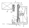
- the figure shows an inventive, designed as a reach truck truck.
- a vehicle frame 1 on which a driver's station 2 is arranged.
- a battery block 3 which supplies all the drives of the reach truck with electrical energy.
- a mast 4 is tilted on the vehicle frame 1 by means of a sliding carriage 5 and slidably mounted in the main direction of travel 6.
- the mast 4 is located in the fully retracted position. Also shown is the fully advanced position 4a of the mast 4.
- the pushing movement of the mast 4 is performed by an actuator 9, which may be designed for example as a hydraulic cylinder or as an electromechanical unit. Regardless of the horizontal displacement of the mast 4, the mast can be tilted about the tilting axis 7.
- the horizontal tilting axis 7 is aligned perpendicular to the main direction of travel 6.
- the mast 4 is telescopically extendable in the usual way.
- the mast 4 has a fixed to the sliding carriage 5 and thus not vertically movable mast, and one or more extension masts, which can be extended relative to the stationary mast upwards.
- a designed as a load fork 8 lifting device is guided up and down on the mast 4.
- a sensor 10 for detecting an elastic oscillation of the mast 4 is attached to the stationary mast of the mast 4, above the pivot axis 7.
- the sensor 10 is designed in the present embodiment as a strain gauge (DMS). Elastic deformations of the stationary mast are detected by the sensor 10.
- An electronic control device 15 evaluates the signal of the sensor 10 and reconstructs the bending state of the mast. In the control device, a control algorithm is implemented, with which an active compensation movement is determined, with which the actuator 9 counteracts the swing.
- a sensor 14 is arranged at the upper end of the Ausfahrmasts, which detects the movement of the upper mast end.
- This sensor 14 may be based on the principle of an acceleration sensor which measures the acceleration of the upper mast end or on the principle of a gyroscope sensor which measures the angular position of the upper mast end.
- the calculation of the compensation movement in the control device 15 can be based exclusively on the signal of the sensor 10, which reflects the mast deflection, exclusively on the signal of the sensor 14, which reflects the movement of the upper mast end, or on the signals of both sensors 10 and 14.
- the control device 15 processes further signals.
- the compensating movement is thereby adapted to the current state of the mast 4, which increases the effectiveness of the compensating movement.
- Most signals are the signal from a sensor 11 for the position of the sliding carriage 5, the signal from a sensor 12 for the height of the fork 8 and the signal from a sensor 13 for the weight of the load.
- the current driving speed and the braking state can be taken into account.
Abstract
Description
Die Erfindung betrifft ein Flurförderzeug, insbesondere Schubmaststapler, mit einem Hubgerüst und einem Stellglied zum Bewegen des Hubgerüsts relativ zu einem Fahrzeugrahmen des Flurförderzeugs.The invention relates to an industrial truck, in particular reach truck, with a mast and an actuator for moving the mast relative to a vehicle frame of the truck.
Bei Flurförderzeugen der genannten Art kann es sich um Schubmaststapler, aber auch um Gegengewichtsgabelstapler handeln. Bei Schubmaststaplern kann das Hubgerüst relativ zum Fahrzeugrahmen horizontal in Hauptfahrrichtung des Flurförderzeugs verschoben werden. Diese Schubbewegung wird mittels eines Stellglieds durchgeführt, welches die zum Verschieben des Hubgerüsts erforderliche Kraft erzeugt. Das Stellglied kann beispielsweise von einem Hydraulikzylinder oder von einem elektromechanischen Aktuator gebildet sein.Forklifts of the type mentioned may be reach trucks, but also counterbalance forklifts. For reach trucks, the mast can be moved horizontally relative to the vehicle frame in the main direction of travel of the truck. This thrust movement is performed by means of an actuator which generates the force required to move the mast. The actuator may be formed for example by a hydraulic cylinder or by an electromechanical actuator.
Weiter kann das Hubgerüst gegenüber dem Fahrzeugrahmen neigbar sein. Bei Schubmaststaplern ist die Neigbarkeit des Hubgerüsts oft zusätzlich zur horizontalen Verschiebbarkeit vorgesehen. Die Neigeachse des Hubgerüsts ist dabei rechtwinklig zur Hauptfahrrichtung des Hubgerüsts ausgerichtet. Bei Gegengewichtsgabelstaplern stellt die Neigbarkeit in der Regel die einzige Bewegungsmöglichkeit des Hubgerüsts relativ zum Fahrzeugrahmen dar. Das Stellglied zum Neigen des Hubgerüsts kann ebenfalls von einem Hydraulikzylinder oder von einem elektromechanischen Aktuator gebildet sein.Further, the mast can be tilted relative to the vehicle frame. In reach trucks, the tiltability of the mast is often provided in addition to the horizontal displaceability. The tilt axis of the mast is aligned at right angles to the main direction of travel of the mast. In counterbalance forklifts, the tilt is usually the only possibility of movement of the mast relative to the vehicle frame. The actuator for tilting the mast can also be formed by a hydraulic cylinder or by an electromechanical actuator.
Bei allen gattungsgemäßen Flurförderzeugen besteht potentiell das Problem, dass das Hubgerüst in bestimmten Betriebssituationen zum Schwingen neigt. Hierbei sind insbesondere Schwingungsbewegungen störend, bei denen die Richtung der Auslenkung des Hubgerüsts der Hauptfahrrichtung des Flurförderzeugs entspricht. Angeregt wird das Hubgerüst zu einer solchen Schwingungsbewegung beispielsweise durch die Schubbewegung des Hubgerüsts, durch die Neigebewegung des Hubgerüsts oder durch ein Bremsen oder Beschleunigen des Flurförderzeugs insgesamt. Insbesondere dann, wenn das teleskopische Hubgerüst nach oben ausgefahren ist, erreicht die Schwingung häufig Amplituden, die so groß sind, dass die Bedienperson die Schwingung erst abklingen lässt, bevor beispielsweise mit der am Hubgerüst befestigten Lastgabel in ein Regal eingefahren wird.In all generic industrial trucks there is potentially the problem that the mast tends to oscillate in certain operating situations. In this case, vibration movements are particularly disturbing, in which the direction of the deflection of the mast corresponds to the main direction of travel of the truck. The mast is stimulated to such a vibration movement, for example by the pushing movement of the mast, by the tilting movement of the mast or by braking or accelerating the truck as a whole. In particular, when the telescopic mast is extended upwards, the vibration often reaches amplitudes that are so great that the operator The vibration can decay before it is retracted, for example, with the fork attached to the mast on a shelf.
Der vorliegenden Erfindung liegt die Aufgabe zugrunde, ein Flurförderzeug zur Verfügung zu stellen, bei dem Schwingungen des Hubgerüsts weitgehend verhindert werden.The present invention has for its object to provide a truck available in the vibrations of the mast are largely prevented.
Diese Aufgabe wird erfindungsgemäß dadurch gelöst, dass mindestens ein Sensor zum Erkennen eines elastischen Schwingens des Hubgerüsts vorgesehen ist, der mit einer elektronischen Steuervorrichtung in Wirkverbindung steht, mit welcher das Stellglied zum Verschieben des Hubgerüsts ansteuerbar ist, derart, dass durch eine Bewegung des Stellglieds dem Schwingen des Hubgerüsts entgegen gewirkt wird. Mit dem Sensor wird die Schwingungsbewegung des Hubgerüsts gemessen. Die elektronische Steuervorrichtung wertet dieses Messsignal aus und steuert das Stellglied derart an, dass die Schwingungsbewegung zumindest annähernd gestoppt wird. Bei der Bewegung des Stellglieds, die dem Schwingen des Hubgerüsts entgegen wirkt, kann es sich um einen oder mehrere Bewegungsimpulse oder um eine periodische Ausgleichsbewegung handeln.This object is achieved in that at least one sensor is provided for detecting an elastic swing of the mast, which is operatively connected to an electronic control device, with which the actuator for moving the mast is controlled, such that by a movement of the actuator the Swinging of the mast is counteracted. The sensor measures the oscillatory motion of the mast. The electronic control device evaluates this measurement signal and controls the actuator in such a way that the oscillatory movement is stopped at least approximately. During the movement of the actuator, which counteracts the swing of the mast, it may be one or more movement pulses or a periodic compensation movement.
Wie einleitend bereits erwähnt, ist die Erfindung vorteilhaft einsetzbar, wenn das Hubgerüsts mittels des Stellglieds in im Wesentlichen horizontaler Richtung bewegbar ist. Bei dem Stellglied handelt es sich dabei um einen Teil der Schubvorrichtung für das Hubgerüsts eines Schubmaststaplers.As already mentioned in the introduction, the invention can be used advantageously if the mast can be moved in a substantially horizontal direction by means of the actuator. The actuator is a part of the thrust device for the mast of a reach truck.
Ebenso ist die Erfindung einsetzbar, wenn das Hubgerüst mittels des Stellglieds um eine im Wesentlichen horizontale Achse neigbar ist. Das Stellglied ist dabei ein Teil der Neigevorrichtung für das Hubgerüst eines Schubmaststaplers, eines Gegengewichtsgabelstaplers oder eines anderen Flurförderzeugs.Likewise, the invention can be used when the mast is tiltable by means of the actuator about a substantially horizontal axis. The actuator is part of the tilting device for the mast of a reach truck, a counterbalance forklift or other truck.
Zweckmäßig ist es weiter, wenn das Stellglied von einem Hydraulikzylinder gebildet ist und die elektronische Steuervorrichtung ein dem Hydraulikzylinder vorgeschaltetes Ventil ansteuert. Bei dem Einsatz eines Hydraulikzylinders als Stellglied kann die übliche Antriebsandordnung für die Bewegung des Hubgerüsts weiter verwendet werden. Lediglich das dem Hydraulikzylinder vorgeschaltete Ventil muss hinsichtlich der Reaktionszeit und des Ansprechverhaltens an die gestiegenen Anforderungen angepasst werden.It is expedient if the actuator is formed by a hydraulic cylinder and the electronic control device controls a valve upstream of the hydraulic cylinder. When using a hydraulic cylinder as an actuator, the usual Antriebsandordnung for the movement of the mast can be used. Only the valve upstream of the hydraulic cylinder has to be considered the response time and the response to the increased requirements.
Mindestens ein Sensor zum Erkennen eines elastischen Schwingens des Hubgerüsts weist mindestens einen Dehnungsmessstreifen auf. Der Dehnungsmessstreifen (DMS) wird an einem nicht ausfahrbaren Standmast des Hubgerüsts befestigt. Er erfasst die durch die Schwingungen des Hubgerüsts hervorgerufenen geringfügigen elastischen Längenänderungen des Standmasts.At least one sensor for detecting an elastic oscillation of the mast has at least one strain gauge. The strain gauge (DMS) is attached to a non-extendable stand of the mast. It detects the caused by the vibrations of the mast slight elastic changes in length of the mast.
Bevorzugt ist der einen Dehnungsmessstreifen aufweisende Sensor oberhalb einer horizontalen Achse angeordnet, um die das Hubgerüst neigbar ist.The sensor having a strain gauge is preferably arranged above a horizontal axis about which the mast can be tilted.
Alternativ oder zusätzlich kann mindestens ein Sensor zum Erkennen eines elastischen Schwingens des Hubgerüsts mindestens einen Beschleunigungssensor oder mindestens einen Gyroskopsensor aufweisen. Der Beschleunigungssensor misst direkt die durch die Schwingungsbewegung auftretende Beschleunigung des freien Mastendes. Im Gegensatz hierzu misst der Gyroskopsensor die während der Schwingungsbewegung stattfindende Änderung der absoluten Winkellage des freien Mastendes.Alternatively or additionally, at least one sensor for detecting an elastic oscillation of the mast can have at least one acceleration sensor or at least one gyroscope sensor. The acceleration sensor measures directly the acceleration of the free end of the mast due to the vibration movement. In contrast, the gyroscope sensor measures the change in the absolute angular position of the free end of the mast that takes place during the oscillation movement.
Vorteilhafterweise ist der einen Beschleunigungssensor oder einen Gyroskopsensor aufweisende Sensor an einem höhenbewegbaren Ausfahrmast des Hubgerüsts angeordnet. Wenn der Sensor oben an dem am weitesten ausfahrbaren Ausfahrmast des Hubgerüsts angeordnet ist, befindet sich der Sensor stets am obersten Ende des Hubgerüsts. Die Schwingungsbewegung weist an dieser Stelle die größte Auslenkung auf und kann folglich dort am besten gemessen werden.Advantageously, the sensor having an acceleration sensor or a gyroscope sensor is arranged on a vertically movable extension mast of the mast. If the sensor is located at the top of the most extendable boom of the mast, the sensor will always be at the top of the mast. The oscillatory motion has the greatest deflection at this point and can therefore be best measured there.
Eine andere mögliche Ausgestaltungsform besteht darin, dass mindestens ein Sensor zum Erkennen eines elastischen Schwingens des Hubgerüsts mindestens einen Druck- oder Kraftsensor aufweist, der die auf das Stellglied wirkende Kraft erfasst. Dies erlaubt ein indirektes Messen der Hubgerüstschwingungen über die auf das Stellglied wirkende Reaktionskraft der Schwingungen. Wenn das Stellglied als Hydraulikzylinder ausgeführt ist, kann mit dem Drucksensors die während des Schwingens auftretende periodische Druckänderung des Hydrauliköls erfasst werden.Another possible embodiment is that at least one sensor for detecting an elastic swinging of the mast has at least one pressure or force sensor which detects the force acting on the actuator. This allows for indirectly measuring the mast vibrations via the reaction force of the vibrations acting on the actuator. If the actuator is designed as a hydraulic cylinder, with the pressure sensor, the periodic pressure change of the hydraulic oil occurring during the swing can be detected.
Gemäß einer zweckmäßigen Weiterbildung der Erfindung ist die elektronische Steuervorrichtung derart ausgeführt, dass die Bewegung des Stellglieds, die dem Schwingen des Hubgerüsts entgegen wirkt, unter Berücksichtigung mindestens eines Betriebsparameters des Flurförderzeugs ermittelt wird.According to an expedient development of the invention, the electronic control device is designed such that the movement of the actuator, which counteracts the swinging of the mast, is determined taking into account at least one operating parameter of the truck.
Ein Betriebsparameter ist von der momentanen horizontalen Position und/oder der momentanen horizontalen Bewegungsgeschwindigkeit des Hubgerüsts gebildet.An operating parameter is formed by the current horizontal position and / or the instantaneous horizontal movement speed of the mast.
Einen weiteren Betriebsparameter stellt die momentane Neigung und/oder die momentane Neigungsgeschwindigkeit des Hubgerüsts dar.Another operating parameter represents the instantaneous inclination and / or the instantaneous inclination speed of the mast.
Ein dritter Betriebsparameter kann von der momentanen Hubhöhe und/oder von der momentanen Hub- oder Senkgeschwindigkeit des Hubgerüsts gebildet sein.A third operating parameter may be formed by the current lifting height and / or by the current lifting or lowering speed of the lifting frame.
Ein weiterer Betriebsparameter ist schließlich von dem Gewicht einer mit dem Hubgerüst angehobenen Last gebildet.Another operating parameter is finally formed by the weight of a load lifted with the mast.
Die genannten Betriebsparameter haben einen wesentlichen Einfluss auf das Schwingungsverhalten des Hubgerüsts. Sie werden deshalb von der Steuervorrichtung bei der Ermittlung der Ausgleichsbewegung berücksichtigt.The mentioned operating parameters have a significant influence on the vibration behavior of the mast. They are therefore taken into account by the control device in determining the compensation movement.
Weiter kommen als zur berücksichtigende Betriebsparameter die momentane Fahrgeschwindigkeit des Flurförderzeugs und der momentane Bremszustand des Flurförderzeugs in Betracht.Next come as to be considered operating parameters, the current speed of the truck and the current braking state of the truck into consideration.
Besonders vorteilhaft ist es, wenn in der elektronischen Steuervorrichtung ein Regelalgorithmus implementiert ist, mit dem eine Stellgröße für die Bewegung des Stellglieds ermittelt wird. Es handelt sich hierbei um einen echten Regelkreis, bei dem die tatsächliche Schwingungsintensität des Hubgerüsts auf die Regelstrecke rückgekoppelt wird. Auf diese Weise gelingt es, ein Schwingen des Hubgerüsts annähernd vollständig auszuschließen.It is particularly advantageous if a control algorithm is implemented in the electronic control device with which a manipulated variable for the movement of the actuator is determined. This is a real control loop in which the actual vibration intensity of the mast is fed back to the controlled system. In this way, it is possible to almost completely exclude rocking of the mast.
Weitere Vorteile und Einzelheiten der Erfindung werden anhand des in der schematischen Figur dargestellten Ausführungsbeispiels näher erläutert.Further advantages and details of the invention will be explained in more detail with reference to the embodiment shown in the schematic figure.
Die Figur zeigt ein erfindungsgemäßes, als Schubmaststapler ausgeführtes Flurförderzeug. Zu erkennen ist ein Fahrzeugrahmen 1, auf dem ein Fahrerstand 2 angeordnet ist. Ebenfalls auf dem Fahrzeugrahmen angeordnet ist ein Batterieblock 3, der sämtliche Antriebe des Schubmaststaplers mit elektrischer Energie versorgt.The figure shows an inventive, designed as a reach truck truck. Evident is a
Ein Hubgerüst 4 ist an dem Fahrzeugrahmen 1 mittels eines Schubschlittens 5 neigbar und in Hauptfahrrichtung 6 verschiebbar gelagert. Das Hubgerüst 4 ist in vollständig zurückgeschobener Position eingezeichnet. Ebenfalls dargestellt ist die vollständig vorgeschobene Position 4a des Hubgerüsts 4. Die Schubbewegung des Hubgerüsts 4 wird von einem Stellglied 9 durchgeführt, das beispielsweise als Hydraulikzylinder oder als elektromechanische Einheit ausgeführt sein kann. Unabhängig vom horizontalen Verschieben des Hubgerüsts 4 kann das Hubgerüst um die Neigeachse 7 geneigt werden. Die waagrechte Neigeachse 7 ist senkrecht zur Hauptfahrrichtung 6 ausgerichtet.A mast 4 is tilted on the
Darüber hinaus ist das Hubgerüst 4 in üblicher Weise teleskopisch nach oben ausfahrbar. Hierzu weist das Hubgerüst 4 einen am Schubschlitten 5 befestigten und damit nicht höhenbewegbaren Standmast auf, sowie einen oder mehrere Ausfahrmasten, die relativ zum Standmast nach oben ausgefahren werden können. Ein als Lastgabel 8 ausgeführtes Lastaufnahmemittel ist am Hubgerüst 4 auf- und abbewegbar geführt.In addition, the mast 4 is telescopically extendable in the usual way. For this purpose, the mast 4 has a fixed to the sliding
Während des Betriebs des Schubmaststaplers treten häufig Betriebssituationen auf, bei denen das Hubgerüst 4 zum Schwingen kommt. Insbesondere treten Schwingungsbewegungen auf, bei denen sich das obere Ende des Hubgerüsts 4 in Richtung 6 nach vorne und hinten bewegt.During operation of the reach truck often occur operating situations in which the mast 4 comes to vibrate. In particular, vibration movements occur in which the upper end of the mast 4 moves in the
Mit der nachfolgend beschriebenen erfindungsgemäßen Anordnung können diese Schwingungen weitgehend vermieden oder schnell kompensiert werden:With the arrangement according to the invention described below, these vibrations can be largely avoided or quickly compensated:
Ein Sensor 10 zum Erkennen eines elastischen Schwingens des Hubgerüsts 4 ist an dem Standmast des Hubgerüsts 4, oberhalb der Schwenkachse 7 befestigt. Der Sensor 10 ist im vorliegenden Ausführungsbeispiel als Dehnungsmessstreifen (DMS) ausgeführt. Elastische Verformungen des Standmasts werden von dem Sensor 10 erfasst. Eine elektronische Steuervorrichtung 15 wertet das Signal des Sensors 10 aus und rekonstruiert den Biegungszustand des Masts. In der Steuervorrichtung ist ein Regelalgorithmus implementiert, mit dem eine aktive Ausgleichsbewegung ermittelt wird, mit welcher das Stellglied 9 dem Schwingen entgegen wirkt.A
Weiter ist am oberen Ende des Ausfahrmasts ein Sensor 14 angeordnet, der die Bewegung des oberen Mastendes erfasst. Dieser Sensor 14 kann auf dem Prinzip eines Beschleunigungssensors, der die Beschleunigung des oberen Mastendes misst, oder auf dem Prinzip eines Gyroskopsensors, der die Winkellage des oberen Mastendes misst, beruhen.Further, a
Die Berechnung der Ausgleichsbewegung in der Steuervorrichtung 15 kann ausschließlich auf dem Signal des Sensors 10, welches die Mastbiegung wiedergibt, ausschließlich auf dem Signal des Sensors 14, welches die Bewegung des oberen Mastendes wiedergibt, oder auf den Signalen beider Sensoren 10 und 14 beruhen.The calculation of the compensation movement in the
Außer dem Signal des Sensors 10 bzw. 14 verarbeitet die Steuervorrichtung 15 noch weitere Signale. Die Ausgleichsbewegung wird dadurch an den momentanen Zustand des Hubgerüsts 4 angepasst, was die Effektivität der Ausgleichsbewegung erhöht. Bei den meisten Signalen handelt es sich um das Signal eines Sensors 11 für die Position des Schubschlittens 5, um das Signal eines Sensors 12 für die Höhe der Lastgabel 8 und um das Signal eines Sensors 13 für das Lastgewicht. Weiter können die momentane Fahrgeschwindigkeit und der Bremszustand (Bremse betätigt oder gelöst) berücksichtigt werden.In addition to the signal from the
Claims (17)
Applications Claiming Priority (1)
| Application Number | Priority Date | Filing Date | Title |
|---|---|---|---|
| DE102007015488A DE102007015488A1 (en) | 2007-03-30 | 2007-03-30 | Vibration compensation on the mast of a truck |
Publications (3)
| Publication Number | Publication Date |
|---|---|
| EP1975114A1 true EP1975114A1 (en) | 2008-10-01 |
| EP1975114B1 EP1975114B1 (en) | 2015-07-29 |
| EP1975114B2 EP1975114B2 (en) | 2021-03-17 |
Family
ID=39639633
Family Applications (1)
| Application Number | Title | Priority Date | Filing Date |
|---|---|---|---|
| EP08004305.2A Active EP1975114B2 (en) | 2007-03-30 | 2008-03-07 | Oscillation compensation for the lifting frame of an industrial truck |
Country Status (2)
| Country | Link |
|---|---|
| EP (1) | EP1975114B2 (en) |
| DE (1) | DE102007015488A1 (en) |
Cited By (14)
| Publication number | Priority date | Publication date | Assignee | Title |
|---|---|---|---|---|
| WO2011032744A1 (en) * | 2009-09-15 | 2011-03-24 | Robert Bosch Gmbh | Load-carrying vehicle with vertically adjustable lifting device |
| DE102010016062A1 (en) | 2010-03-22 | 2011-09-22 | Technische Universität München | Damping or avoiding vibrations in industrial trucks |
| EP2500238A3 (en) * | 2011-03-18 | 2013-12-25 | The Raymond Corporation | Dynamic vibration control systems and methods for industrial lift trucks |
| US8731785B2 (en) | 2011-03-18 | 2014-05-20 | The Raymond Corporation | Dynamic stability control systems and methods for industrial lift trucks |
| US8763990B2 (en) | 2012-03-20 | 2014-07-01 | The Raymond Corporation | Turn stability systems and methods for lift trucks |
| DE102013100191A1 (en) | 2013-01-10 | 2014-07-10 | Linde Material Handling Gmbh | Method for detecting lifting device vibration in truck with lifting device, involves calculating frequency, amplitude and phase position of vibration of lifting device by control computer from detected distances to surrounding points |
| US9002557B2 (en) | 2013-03-14 | 2015-04-07 | The Raymond Corporation | Systems and methods for maintaining an industrial lift truck within defined bounds |
| EP2881358A1 (en) * | 2013-12-04 | 2015-06-10 | KION Warehouse Systems GmbH | Industrial truck |
| DE102014104745A1 (en) | 2014-04-03 | 2015-10-08 | Linde Material Handling Gmbh | Truck with compensation of lift mast vibrations |
| US9302893B2 (en) | 2013-02-07 | 2016-04-05 | The Raymond Corporation | Vibration control systems and methods for industrial lift trucks |
| DE102016124506A1 (en) | 2016-12-15 | 2018-06-21 | Jungheinrich Aktiengesellschaft | Truck with a control unit for controlling the movement of a load and a corresponding method |
| DE102017103043A1 (en) | 2017-02-15 | 2018-08-16 | Jungheinrich Aktiengesellschaft | Truck with a mast |
| US10071894B2 (en) | 2015-08-03 | 2018-09-11 | The Raymond Corporation | Oscillation damping for a material handling vehicle |
| CN109279268A (en) * | 2018-12-05 | 2019-01-29 | 大连英蕴科技有限公司 | Vertical conveyor and method in a kind of ship |
Families Citing this family (2)
| Publication number | Priority date | Publication date | Assignee | Title |
|---|---|---|---|---|
| DE102016123541A1 (en) | 2016-12-06 | 2018-06-07 | Jungheinrich Aktiengesellschaft | Method for automatic alignment of a truck in a warehouse and system of an industrial truck and a warehouse |
| DE102016124505A1 (en) * | 2016-12-15 | 2018-06-21 | Jungheinrich Aktiengesellschaft | Truck with a control unit for controlling the movement of a piston rod of a hydraulic cylinder and such a method |
Citations (5)
| Publication number | Priority date | Publication date | Assignee | Title |
|---|---|---|---|---|
| EP0427001A1 (en) * | 1989-11-10 | 1991-05-15 | Jungheinrich Aktiengesellschaft | Lift truck with a movably arranged lift mast |
| DE4408757A1 (en) * | 1994-03-15 | 1995-09-21 | Crown Gabelstapler Gmbh | Fork lift truck with raisable load carrier |
| GB2379434A (en) * | 2001-09-10 | 2003-03-12 | Lansing Linde Ltd | A vibration absorber for a lift truck |
| DE102004048519A1 (en) * | 2004-08-23 | 2006-03-02 | Sandt Logistik Gmbh | Drive controller for shelf storage apparatus, influences motor parameter based on measurement of oscillation of shelf storage apparatus |
| WO2008006928A1 (en) | 2006-07-12 | 2008-01-17 | Rocla Oyj | A method and an arrangement for dampening vibrations in a mast structure |
Family Cites Families (6)
| Publication number | Priority date | Publication date | Assignee | Title |
|---|---|---|---|---|
| DE3122720C1 (en) | 1981-06-06 | 1983-01-13 | Jungheinrich Unternehmensverwaltung Kg, 2000 Hamburg | Method of braking a stacking vehicle with an extendable load-bearing element and a lifting framework, and a stacking vehicle, in particular a high-bay stacker, for carrying out the method |
| DE3210951A1 (en) | 1982-03-25 | 1983-10-13 | Jungheinrich Unternehmensverwaltung Kg, 2000 Hamburg | Stacker vehicle with lift frame |
| DE19641192C2 (en) | 1996-09-24 | 2002-10-31 | Siemens Ag | Handling device, in particular storage and retrieval machine |
| DE10054789A1 (en) | 2000-11-04 | 2002-05-08 | Still Wagner Gmbh & Co Kg | Industrial truck with a mast and an additional movement device for a load handler |
| DE10305902B4 (en) | 2003-02-13 | 2006-11-30 | Jungheinrich Aktiengesellschaft | Method for operating a reach truck and reach truck for carrying out the method |
| DE10349123A1 (en) | 2003-10-22 | 2005-05-19 | Still Wagner Gmbh & Co Kg | Hoist, especially for a high rack forklift |
-
2007
- 2007-03-30 DE DE102007015488A patent/DE102007015488A1/en not_active Withdrawn
-
2008
- 2008-03-07 EP EP08004305.2A patent/EP1975114B2/en active Active
Patent Citations (5)
| Publication number | Priority date | Publication date | Assignee | Title |
|---|---|---|---|---|
| EP0427001A1 (en) * | 1989-11-10 | 1991-05-15 | Jungheinrich Aktiengesellschaft | Lift truck with a movably arranged lift mast |
| DE4408757A1 (en) * | 1994-03-15 | 1995-09-21 | Crown Gabelstapler Gmbh | Fork lift truck with raisable load carrier |
| GB2379434A (en) * | 2001-09-10 | 2003-03-12 | Lansing Linde Ltd | A vibration absorber for a lift truck |
| DE102004048519A1 (en) * | 2004-08-23 | 2006-03-02 | Sandt Logistik Gmbh | Drive controller for shelf storage apparatus, influences motor parameter based on measurement of oscillation of shelf storage apparatus |
| WO2008006928A1 (en) | 2006-07-12 | 2008-01-17 | Rocla Oyj | A method and an arrangement for dampening vibrations in a mast structure |
Cited By (21)
| Publication number | Priority date | Publication date | Assignee | Title |
|---|---|---|---|---|
| CN102482066A (en) * | 2009-09-15 | 2012-05-30 | 罗伯特·博世有限公司 | Load-carrying vehicle with vertically adjustable lifting device |
| CN102482066B (en) * | 2009-09-15 | 2014-11-26 | 罗伯特·博世有限公司 | Load-carrying vehicle with vertically adjustable lifting device |
| WO2011032744A1 (en) * | 2009-09-15 | 2011-03-24 | Robert Bosch Gmbh | Load-carrying vehicle with vertically adjustable lifting device |
| DE102010016062A1 (en) | 2010-03-22 | 2011-09-22 | Technische Universität München | Damping or avoiding vibrations in industrial trucks |
| EP2368832A1 (en) | 2010-03-22 | 2011-09-28 | Technische Universität München | Damping or prevention of vibrations in industrial trucks |
| US8944744B2 (en) | 2010-03-22 | 2015-02-03 | Technische Universität München | Damping or prevention of vibrations in industrial trucks |
| EP2500238A3 (en) * | 2011-03-18 | 2013-12-25 | The Raymond Corporation | Dynamic vibration control systems and methods for industrial lift trucks |
| US8731785B2 (en) | 2011-03-18 | 2014-05-20 | The Raymond Corporation | Dynamic stability control systems and methods for industrial lift trucks |
| US9403667B2 (en) | 2011-03-18 | 2016-08-02 | The Raymond Corporation | Dynamic vibration control systems and methods for industrial lift trucks |
| US8763990B2 (en) | 2012-03-20 | 2014-07-01 | The Raymond Corporation | Turn stability systems and methods for lift trucks |
| DE102013100191A1 (en) | 2013-01-10 | 2014-07-10 | Linde Material Handling Gmbh | Method for detecting lifting device vibration in truck with lifting device, involves calculating frequency, amplitude and phase position of vibration of lifting device by control computer from detected distances to surrounding points |
| US9302893B2 (en) | 2013-02-07 | 2016-04-05 | The Raymond Corporation | Vibration control systems and methods for industrial lift trucks |
| US9002557B2 (en) | 2013-03-14 | 2015-04-07 | The Raymond Corporation | Systems and methods for maintaining an industrial lift truck within defined bounds |
| EP2881358A1 (en) * | 2013-12-04 | 2015-06-10 | KION Warehouse Systems GmbH | Industrial truck |
| DE102014104745A1 (en) | 2014-04-03 | 2015-10-08 | Linde Material Handling Gmbh | Truck with compensation of lift mast vibrations |
| US10071894B2 (en) | 2015-08-03 | 2018-09-11 | The Raymond Corporation | Oscillation damping for a material handling vehicle |
| DE102016124506A1 (en) | 2016-12-15 | 2018-06-21 | Jungheinrich Aktiengesellschaft | Truck with a control unit for controlling the movement of a load and a corresponding method |
| US10549973B2 (en) | 2016-12-15 | 2020-02-04 | Jungheinrich Aktiengesellschaft | Industrial truck having a control unit for regulating the movement of a load and method therefor |
| DE102017103043A1 (en) | 2017-02-15 | 2018-08-16 | Jungheinrich Aktiengesellschaft | Truck with a mast |
| EP3363766A1 (en) * | 2017-02-15 | 2018-08-22 | Jungheinrich Aktiengesellschaft | Industrial truck with a lifting frame |
| CN109279268A (en) * | 2018-12-05 | 2019-01-29 | 大连英蕴科技有限公司 | Vertical conveyor and method in a kind of ship |
Also Published As
| Publication number | Publication date |
|---|---|
| EP1975114B1 (en) | 2015-07-29 |
| DE102007015488A1 (en) | 2008-10-02 |
| EP1975114B2 (en) | 2021-03-17 |
Similar Documents
| Publication | Publication Date | Title |
|---|---|---|
| EP1975114B1 (en) | Oscillation compensation for the lifting frame of an industrial truck | |
| DE102008020592B4 (en) | Procedure for vibration damping in industrial trucks | |
| DE102008020595B4 (en) | Procedure for vibration damping in industrial trucks | |
| EP2272785B1 (en) | Method for controlling a drive of a crane | |
| EP3408208B1 (en) | Crane, and method for controlling such a crane | |
| EP3289151B1 (en) | Drivable working machine and method for operating same | |
| DE102017126386B4 (en) | Construction machine with boom | |
| DE102016213236B4 (en) | ELECTRONIC VALVE ACTUATION CONTROL AND PRESSURE COMPENSATION | |
| EP2636637A1 (en) | Lifting device of an industrial truck | |
| EP2881358B1 (en) | Industrial truck | |
| EP0985629B1 (en) | Crane | |
| DE102007024817B4 (en) | Industrial truck with a mast and an actuator to compensate for vibrations | |
| EP1359113B2 (en) | Lift truck with a device for moving the lift mast | |
| EP3336050B1 (en) | Industrial truck with a control unit for regulating the movement of a piston rod of a hydraulic cylinder and such a method | |
| DE102006012982A1 (en) | Reach truck with a mast | |
| DE102016106459A1 (en) | Work vehicle with articulated steering and load-dependent steering angle limitation | |
| EP1780171B1 (en) | Lift truck with a support leg arrangement | |
| EP1528035B1 (en) | Lifting device for high rise shelves | |
| EP3532425B1 (en) | Method for the compensation of diagonal pull in cranes | |
| EP3976889B1 (en) | Hydrostatic lifting unit, mobile working machine therewith, and method for load determination on the lifting unit | |
| DE102017202009A1 (en) | crane | |
| DE102008020593A1 (en) | Method for active oscillation damping for industrial truck, involves detecting oscillations by sensor, damping oscillations actively, and controlling left lifting cylinder and right lifting cylinder by control unit | |
| EP1371604A2 (en) | Lifting device for an industrial truck | |
| EP3042876B1 (en) | Industrial truck with a tiltable lifting frame | |
| DE102019115308A1 (en) | Method for controlling a working hydraulic function of an industrial truck |
Legal Events
| Date | Code | Title | Description |
|---|---|---|---|
| PUAI | Public reference made under article 153(3) epc to a published international application that has entered the european phase |
Free format text: ORIGINAL CODE: 0009012 |
|
| AK | Designated contracting states |
Kind code of ref document: A1 Designated state(s): AT BE BG CH CY CZ DE DK EE ES FI FR GB GR HR HU IE IS IT LI LT LU LV MC MT NL NO PL PT RO SE SI SK TR |
|
| AX | Request for extension of the european patent |
Extension state: AL BA MK RS |
|
| 17P | Request for examination filed |
Effective date: 20090305 |
|
| 17Q | First examination report despatched |
Effective date: 20090424 |
|
| AKX | Designation fees paid |
Designated state(s): DE IT SE |
|
| RAP1 | Party data changed (applicant data changed or rights of an application transferred) |
Owner name: STILL GMBH |
|
| GRAP | Despatch of communication of intention to grant a patent |
Free format text: ORIGINAL CODE: EPIDOSNIGR1 |
|
| INTG | Intention to grant announced |
Effective date: 20150417 |
|
| GRAS | Grant fee paid |
Free format text: ORIGINAL CODE: EPIDOSNIGR3 |
|
| GRAA | (expected) grant |
Free format text: ORIGINAL CODE: 0009210 |
|
| STAA | Information on the status of an ep patent application or granted ep patent |
Free format text: STATUS: THE PATENT HAS BEEN GRANTED |
|
| AK | Designated contracting states |
Kind code of ref document: B1 Designated state(s): DE IT SE |
|
| REG | Reference to a national code |
Ref country code: DE Ref legal event code: R096 Ref document number: 502008013187 Country of ref document: DE |
|
| REG | Reference to a national code |
Ref country code: SE Ref legal event code: TRGR |
|
| REG | Reference to a national code |
Ref country code: DE Ref legal event code: R026 Ref document number: 502008013187 Country of ref document: DE |
|
| PLBI | Opposition filed |
Free format text: ORIGINAL CODE: 0009260 |
|
| PLAX | Notice of opposition and request to file observation + time limit sent |
Free format text: ORIGINAL CODE: EPIDOSNOBS2 |
|
| 26 | Opposition filed |
Opponent name: JUNGHEINRICH AKTIENGESELLSCHAFT Effective date: 20160429 |
|
| PLAF | Information modified related to communication of a notice of opposition and request to file observations + time limit |
Free format text: ORIGINAL CODE: EPIDOSCOBS2 |
|
| PLBB | Reply of patent proprietor to notice(s) of opposition received |
Free format text: ORIGINAL CODE: EPIDOSNOBS3 |
|
| REG | Reference to a national code |
Ref country code: DE Ref legal event code: R082 Ref document number: 502008013187 Country of ref document: DE Representative=s name: PATENTSHIP PATENTANWALTSGESELLSCHAFT MBH, DE |
|
| REG | Reference to a national code |
Ref country code: DE Ref legal event code: R082 Ref document number: 502008013187 Country of ref document: DE Representative=s name: PATENTSHIP PATENTANWALTSGESELLSCHAFT MBH, DE |
|
| PLAB | Opposition data, opponent's data or that of the opponent's representative modified |
Free format text: ORIGINAL CODE: 0009299OPPO |
|
| R26 | Opposition filed (corrected) |
Opponent name: JUNGHEINRICH AKTIENGESELLSCHAFT Effective date: 20160429 |
|
| APAH | Appeal reference modified |
Free format text: ORIGINAL CODE: EPIDOSCREFNO |
|
| APBM | Appeal reference recorded |
Free format text: ORIGINAL CODE: EPIDOSNREFNO |
|
| APBP | Date of receipt of notice of appeal recorded |
Free format text: ORIGINAL CODE: EPIDOSNNOA2O |
|
| PLAB | Opposition data, opponent's data or that of the opponent's representative modified |
Free format text: ORIGINAL CODE: 0009299OPPO |
|
| APBM | Appeal reference recorded |
Free format text: ORIGINAL CODE: EPIDOSNREFNO |
|
| APBP | Date of receipt of notice of appeal recorded |
Free format text: ORIGINAL CODE: EPIDOSNNOA2O |
|
| R26 | Opposition filed (corrected) |
Opponent name: JUNGHEINRICH AKTIENGESELLSCHAFT Effective date: 20160429 |
|
| APBQ | Date of receipt of statement of grounds of appeal recorded |
Free format text: ORIGINAL CODE: EPIDOSNNOA3O |
|
| APBQ | Date of receipt of statement of grounds of appeal recorded |
Free format text: ORIGINAL CODE: EPIDOSNNOA3O |
|
| APBU | Appeal procedure closed |
Free format text: ORIGINAL CODE: EPIDOSNNOA9O |
|
| PUAH | Patent maintained in amended form |
Free format text: ORIGINAL CODE: 0009272 |
|
| STAA | Information on the status of an ep patent application or granted ep patent |
Free format text: STATUS: PATENT MAINTAINED AS AMENDED |
|
| 27A | Patent maintained in amended form |
Effective date: 20210317 |
|
| AK | Designated contracting states |
Kind code of ref document: B2 Designated state(s): DE IT SE |
|
| REG | Reference to a national code |
Ref country code: DE Ref legal event code: R102 Ref document number: 502008013187 Country of ref document: DE |
|
| REG | Reference to a national code |
Ref country code: SE Ref legal event code: RPEO |
|
| PGFP | Annual fee paid to national office [announced via postgrant information from national office to epo] |
Ref country code: SE Payment date: 20230315 Year of fee payment: 16 Ref country code: DE Payment date: 20230320 Year of fee payment: 16 |
|
| P01 | Opt-out of the competence of the unified patent court (upc) registered |
Effective date: 20230518 |
|
| PGFP | Annual fee paid to national office [announced via postgrant information from national office to epo] |
Ref country code: IT Payment date: 20230331 Year of fee payment: 16 |