EP1975028A2 - Driving support method and driving support apparatus for hybrid vehicle - Google Patents
Driving support method and driving support apparatus for hybrid vehicle Download PDFInfo
- Publication number
- EP1975028A2 EP1975028A2 EP08153068A EP08153068A EP1975028A2 EP 1975028 A2 EP1975028 A2 EP 1975028A2 EP 08153068 A EP08153068 A EP 08153068A EP 08153068 A EP08153068 A EP 08153068A EP 1975028 A2 EP1975028 A2 EP 1975028A2
- Authority
- EP
- European Patent Office
- Prior art keywords
- destination
- travel
- hybrid vehicle
- predicted
- hybrid
- Prior art date
- Legal status (The legal status is an assumption and is not a legal conclusion. Google has not performed a legal analysis and makes no representation as to the accuracy of the status listed.)
- Granted
Links
- 238000000034 method Methods 0.000 title claims abstract description 22
- 238000013500 data storage Methods 0.000 claims description 16
- 238000002485 combustion reaction Methods 0.000 claims description 15
- 238000007726 management method Methods 0.000 description 11
- 230000001133 acceleration Effects 0.000 description 3
- 238000010586 diagram Methods 0.000 description 3
- 102220103394 rs772658698 Human genes 0.000 description 2
- 230000005540 biological transmission Effects 0.000 description 1
- 238000004891 communication Methods 0.000 description 1
- 238000005516 engineering process Methods 0.000 description 1
- 239000000446 fuel Substances 0.000 description 1
- 230000006870 function Effects 0.000 description 1
- 238000010348 incorporation Methods 0.000 description 1
- 230000003287 optical effect Effects 0.000 description 1
- 102220037243 rs73777558 Human genes 0.000 description 1
Images



Classifications
-
- B—PERFORMING OPERATIONS; TRANSPORTING
- B60—VEHICLES IN GENERAL
- B60W—CONJOINT CONTROL OF VEHICLE SUB-UNITS OF DIFFERENT TYPE OR DIFFERENT FUNCTION; CONTROL SYSTEMS SPECIALLY ADAPTED FOR HYBRID VEHICLES; ROAD VEHICLE DRIVE CONTROL SYSTEMS FOR PURPOSES NOT RELATED TO THE CONTROL OF A PARTICULAR SUB-UNIT
- B60W30/00—Purposes of road vehicle drive control systems not related to the control of a particular sub-unit, e.g. of systems using conjoint control of vehicle sub-units
- B60W30/18—Propelling the vehicle
- B60W30/188—Controlling power parameters of the driveline, e.g. determining the required power
-
- B—PERFORMING OPERATIONS; TRANSPORTING
- B60—VEHICLES IN GENERAL
- B60W—CONJOINT CONTROL OF VEHICLE SUB-UNITS OF DIFFERENT TYPE OR DIFFERENT FUNCTION; CONTROL SYSTEMS SPECIALLY ADAPTED FOR HYBRID VEHICLES; ROAD VEHICLE DRIVE CONTROL SYSTEMS FOR PURPOSES NOT RELATED TO THE CONTROL OF A PARTICULAR SUB-UNIT
- B60W10/00—Conjoint control of vehicle sub-units of different type or different function
- B60W10/04—Conjoint control of vehicle sub-units of different type or different function including control of propulsion units
- B60W10/06—Conjoint control of vehicle sub-units of different type or different function including control of propulsion units including control of combustion engines
-
- B—PERFORMING OPERATIONS; TRANSPORTING
- B60—VEHICLES IN GENERAL
- B60W—CONJOINT CONTROL OF VEHICLE SUB-UNITS OF DIFFERENT TYPE OR DIFFERENT FUNCTION; CONTROL SYSTEMS SPECIALLY ADAPTED FOR HYBRID VEHICLES; ROAD VEHICLE DRIVE CONTROL SYSTEMS FOR PURPOSES NOT RELATED TO THE CONTROL OF A PARTICULAR SUB-UNIT
- B60W10/00—Conjoint control of vehicle sub-units of different type or different function
- B60W10/04—Conjoint control of vehicle sub-units of different type or different function including control of propulsion units
- B60W10/08—Conjoint control of vehicle sub-units of different type or different function including control of propulsion units including control of electric propulsion units, e.g. motors or generators
-
- B—PERFORMING OPERATIONS; TRANSPORTING
- B60—VEHICLES IN GENERAL
- B60W—CONJOINT CONTROL OF VEHICLE SUB-UNITS OF DIFFERENT TYPE OR DIFFERENT FUNCTION; CONTROL SYSTEMS SPECIALLY ADAPTED FOR HYBRID VEHICLES; ROAD VEHICLE DRIVE CONTROL SYSTEMS FOR PURPOSES NOT RELATED TO THE CONTROL OF A PARTICULAR SUB-UNIT
- B60W10/00—Conjoint control of vehicle sub-units of different type or different function
- B60W10/24—Conjoint control of vehicle sub-units of different type or different function including control of energy storage means
- B60W10/26—Conjoint control of vehicle sub-units of different type or different function including control of energy storage means for electrical energy, e.g. batteries or capacitors
-
- B—PERFORMING OPERATIONS; TRANSPORTING
- B60—VEHICLES IN GENERAL
- B60W—CONJOINT CONTROL OF VEHICLE SUB-UNITS OF DIFFERENT TYPE OR DIFFERENT FUNCTION; CONTROL SYSTEMS SPECIALLY ADAPTED FOR HYBRID VEHICLES; ROAD VEHICLE DRIVE CONTROL SYSTEMS FOR PURPOSES NOT RELATED TO THE CONTROL OF A PARTICULAR SUB-UNIT
- B60W20/00—Control systems specially adapted for hybrid vehicles
- B60W20/10—Controlling the power contribution of each of the prime movers to meet required power demand
- B60W20/11—Controlling the power contribution of each of the prime movers to meet required power demand using model predictive control [MPC] strategies, i.e. control methods based on models predicting performance
-
- B—PERFORMING OPERATIONS; TRANSPORTING
- B60—VEHICLES IN GENERAL
- B60W—CONJOINT CONTROL OF VEHICLE SUB-UNITS OF DIFFERENT TYPE OR DIFFERENT FUNCTION; CONTROL SYSTEMS SPECIALLY ADAPTED FOR HYBRID VEHICLES; ROAD VEHICLE DRIVE CONTROL SYSTEMS FOR PURPOSES NOT RELATED TO THE CONTROL OF A PARTICULAR SUB-UNIT
- B60W20/00—Control systems specially adapted for hybrid vehicles
- B60W20/10—Controlling the power contribution of each of the prime movers to meet required power demand
- B60W20/12—Controlling the power contribution of each of the prime movers to meet required power demand using control strategies taking into account route information
-
- B—PERFORMING OPERATIONS; TRANSPORTING
- B60—VEHICLES IN GENERAL
- B60W—CONJOINT CONTROL OF VEHICLE SUB-UNITS OF DIFFERENT TYPE OR DIFFERENT FUNCTION; CONTROL SYSTEMS SPECIALLY ADAPTED FOR HYBRID VEHICLES; ROAD VEHICLE DRIVE CONTROL SYSTEMS FOR PURPOSES NOT RELATED TO THE CONTROL OF A PARTICULAR SUB-UNIT
- B60W50/00—Details of control systems for road vehicle drive control not related to the control of a particular sub-unit, e.g. process diagnostic or vehicle driver interfaces
- B60W50/0097—Predicting future conditions
-
- B—PERFORMING OPERATIONS; TRANSPORTING
- B60—VEHICLES IN GENERAL
- B60W—CONJOINT CONTROL OF VEHICLE SUB-UNITS OF DIFFERENT TYPE OR DIFFERENT FUNCTION; CONTROL SYSTEMS SPECIALLY ADAPTED FOR HYBRID VEHICLES; ROAD VEHICLE DRIVE CONTROL SYSTEMS FOR PURPOSES NOT RELATED TO THE CONTROL OF A PARTICULAR SUB-UNIT
- B60W2510/00—Input parameters relating to a particular sub-units
- B60W2510/24—Energy storage means
- B60W2510/242—Energy storage means for electrical energy
- B60W2510/244—Charge state
-
- B—PERFORMING OPERATIONS; TRANSPORTING
- B60—VEHICLES IN GENERAL
- B60W—CONJOINT CONTROL OF VEHICLE SUB-UNITS OF DIFFERENT TYPE OR DIFFERENT FUNCTION; CONTROL SYSTEMS SPECIALLY ADAPTED FOR HYBRID VEHICLES; ROAD VEHICLE DRIVE CONTROL SYSTEMS FOR PURPOSES NOT RELATED TO THE CONTROL OF A PARTICULAR SUB-UNIT
- B60W2552/00—Input parameters relating to infrastructure
- B60W2552/20—Road profile, i.e. the change in elevation or curvature of a plurality of continuous road segments
-
- B—PERFORMING OPERATIONS; TRANSPORTING
- B60—VEHICLES IN GENERAL
- B60W—CONJOINT CONTROL OF VEHICLE SUB-UNITS OF DIFFERENT TYPE OR DIFFERENT FUNCTION; CONTROL SYSTEMS SPECIALLY ADAPTED FOR HYBRID VEHICLES; ROAD VEHICLE DRIVE CONTROL SYSTEMS FOR PURPOSES NOT RELATED TO THE CONTROL OF A PARTICULAR SUB-UNIT
- B60W2556/00—Input parameters relating to data
- B60W2556/10—Historical data
-
- B—PERFORMING OPERATIONS; TRANSPORTING
- B60—VEHICLES IN GENERAL
- B60W—CONJOINT CONTROL OF VEHICLE SUB-UNITS OF DIFFERENT TYPE OR DIFFERENT FUNCTION; CONTROL SYSTEMS SPECIALLY ADAPTED FOR HYBRID VEHICLES; ROAD VEHICLE DRIVE CONTROL SYSTEMS FOR PURPOSES NOT RELATED TO THE CONTROL OF A PARTICULAR SUB-UNIT
- B60W2556/00—Input parameters relating to data
- B60W2556/45—External transmission of data to or from the vehicle
- B60W2556/50—External transmission of data to or from the vehicle of positioning data, e.g. GPS [Global Positioning System] data
-
- Y—GENERAL TAGGING OF NEW TECHNOLOGICAL DEVELOPMENTS; GENERAL TAGGING OF CROSS-SECTIONAL TECHNOLOGIES SPANNING OVER SEVERAL SECTIONS OF THE IPC; TECHNICAL SUBJECTS COVERED BY FORMER USPC CROSS-REFERENCE ART COLLECTIONS [XRACs] AND DIGESTS
- Y02—TECHNOLOGIES OR APPLICATIONS FOR MITIGATION OR ADAPTATION AGAINST CLIMATE CHANGE
- Y02T—CLIMATE CHANGE MITIGATION TECHNOLOGIES RELATED TO TRANSPORTATION
- Y02T10/00—Road transport of goods or passengers
- Y02T10/10—Internal combustion engine [ICE] based vehicles
- Y02T10/40—Engine management systems
-
- Y—GENERAL TAGGING OF NEW TECHNOLOGICAL DEVELOPMENTS; GENERAL TAGGING OF CROSS-SECTIONAL TECHNOLOGIES SPANNING OVER SEVERAL SECTIONS OF THE IPC; TECHNICAL SUBJECTS COVERED BY FORMER USPC CROSS-REFERENCE ART COLLECTIONS [XRACs] AND DIGESTS
- Y02—TECHNOLOGIES OR APPLICATIONS FOR MITIGATION OR ADAPTATION AGAINST CLIMATE CHANGE
- Y02T—CLIMATE CHANGE MITIGATION TECHNOLOGIES RELATED TO TRANSPORTATION
- Y02T10/00—Road transport of goods or passengers
- Y02T10/60—Other road transportation technologies with climate change mitigation effect
- Y02T10/62—Hybrid vehicles
-
- Y—GENERAL TAGGING OF NEW TECHNOLOGICAL DEVELOPMENTS; GENERAL TAGGING OF CROSS-SECTIONAL TECHNOLOGIES SPANNING OVER SEVERAL SECTIONS OF THE IPC; TECHNICAL SUBJECTS COVERED BY FORMER USPC CROSS-REFERENCE ART COLLECTIONS [XRACs] AND DIGESTS
- Y02—TECHNOLOGIES OR APPLICATIONS FOR MITIGATION OR ADAPTATION AGAINST CLIMATE CHANGE
- Y02T—CLIMATE CHANGE MITIGATION TECHNOLOGIES RELATED TO TRANSPORTATION
- Y02T10/00—Road transport of goods or passengers
- Y02T10/80—Technologies aiming to reduce greenhouse gasses emissions common to all road transportation technologies
- Y02T10/84—Data processing systems or methods, management, administration
Definitions
- the present invention relates to a driving support method and a driving support apparatus for a hybrid vehicle.
- a hybrid vehicle employing an internal combustion engine and an electric motor as driving power sources is well known in the art in comparison with a normal vehicle employing only an internal combustion engine as a power source.
- a vehicle which stores electric power supplied by an external infrastructure in a battery is suggested.
- As a power charging method for such a hybrid vehicle when the amount of charge remaining in the battery is reduced, electric power is charged by means of a charging station for an electric vehicle or an exclusive battery charger plugged into a house outlet.
- the hybrid vehicle when the amount of charge remaining in the battery goes below a low threshold value while the vehicle is traveling, the hybrid vehicle stops using the electric motor as a power source and travels only using the internal combustion engine, so that the fuel efficiency might become low. This is not recommended in terms of energy saving and low-emission technology.
- the hybrid vehicle when a user inputs a travel schedule in advance, the hybrid vehicle assigns the amount of charge remaining in the battery to travel on each of a plurality of routes. Specifically, the user inputs a travel schedule such as a departure point at which the user charges the battery, a point at which the user will pass through, and a next charge point in advance.
- a navigation ECU searches for routes on the basis of the travel schedule and calculates the travel distance of each route.
- the navigation ECU assigns the amount of charge remaining in the battery to each route on the basis of the travel distances and outputs the necessary amount of charge (hereinafter referred to as SOC usage) for each route to a vehicle ECU. For example, when the user plans to travel on both a route A and a route B before the vehicle arrives at a next charge point, the SOC usage for the route A is set at 40% and the SOC usage for the route B is set at 60% on the basis of the distances of the two routes.
- SOC usage the necessary amount of charge
- the user may take advantage of the efficient assignment of the amount of charge remaining in the battery on the basis of the input schedule.
- the apparatus described above cannot assign the amount of charge remaining in the battery. Further, in the case that the driver of the vehicle often travels along the same route, it is bothersome for the driver to input the travel schedule every time.
- various exemplary implementations of the principles described herein provide a driving support method for a hybrid vehicle whose driving power sources are an internal combustion engine and an electric motor operating with electric power supplied from an electric charger and which includes a hybrid control device for controlling the internal combustion engine and the electric motor; including: predicting a destination on the basis of past travel history of the hybrid vehicle, provided that the destination is not set; calculating a degree of reliability of the predicted destination; and controlling the hybrid control device on the basis of the degree of reliability.
- a driving support apparatus for a hybrid vehicle whose driving power sources are an internal combustion engine and an electric motor operating with electric power supplied from an electric charger and which includes a hybrid control device for controlling the internal combustion engine and the electric motor; including: a vehicle position calculating device for calculating a position of the hybrid vehicle; a setting determining device for determining whether a destination is set; a history data storage device for storing travel history data of the hybrid vehicle; a destination predicting device for predicting a destination on the basis of the travel history data, provided that the destination is not set; a degree of reliability calculating device for calculating a degree of reliability of the predicted destination on the basis of the travel history data; and a controlling device for controlling the hybrid control device on the basis of the degree of reliability.
- the driving support apparatus for a hybrid vehicle further including: a route obtaining device for obtaining a route to the predicted destination on the basis of the travel history data, wherein: the controlling device determines whether the degree of reliability is equal to or greater than a predetermined value and controls the hybrid control device on the basis of the route to the predicted destination, provided that the degree of reliability is equal to or greater than the predetermined value.
- the driving support apparatus for a hybrid vehicle further including: a travel distance predicting device for calculating a predicted travel distance to the predicted destination, wherein: the controlling device determines whether the hybrid vehicle is able to travel to the predicted destination using only the electric motor on the basis of the predicted travel distance and activates, provided that it is possible for the hybrid vehicle to travel to the predicted destination with using only the electric motor, only the electric motor using the hybrid control device, or otherwise activates, provided that the hybrid vehicle is not able to travel to the predicted destination using only the electric motor, both the electric motor and the internal combustion engine by the hybrid control device in a way that the amount of charge remaining in the electric charger becomes a predetermined low limit when the hybrid vehicle arrives at the predicted destination.
- the destination when a destination is not set, the destination is predicted and the degree of reliability of the predicted destination is calculated. Further a hybrid control device is controlled on the basis of the calculated degree of reliability. Therefore, even when a travel schedule is not set in advance, it may be possible for the driver to travel in efficient hybrid mode.
- the driving support apparatus for hybrid vehicle predicts the destination and calculates the degree of reliability of the predicted destination. Further the driving support apparatus for hybrid vehicle controls the hybrid control device on the basis of the calculated degree of reliability, so that even when a travel schedule is not set in advance, it may be possible for the driver to travel in efficient hybrid mode.
- the hybrid control device is controlled on the basis of the route to the predicted destination, so that, when the degree of reliability of the destination is high, it may be possible for the driver to travel on the route in efficient hybrid mode.
- the vehicle when it is determined that the vehicle is able to travel to the predicted destination only with using the electric motor, the vehicle travels only with using the electric motor as a driving power source. Meanwhile, when it is determined that the vehicle is not able to travel to the predicted destination only with using the electric motor, the vehicle travels with using both of the electric motor and the internal combustion engine in a way that the amount of charge remaining in a charger becomes a predetermined low limit. Therefore, it may be possible for the vehicle to travel in efficient hybrid mode according to the amount of charge in the charger.
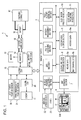
- FIG. 1 is a block diagram showing a hybrid system.
- FIG. 2 is a diagram showing a data structure of history data.
- FIG. 3 is a flowchart showing procedures in a current embodiment.
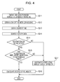
- FIG. 4 is a flowchart showing procedures of destination predicting processing.
- FIG. 5 is a flowchart showing procedures of history data accumulating processing.
- FIG. 1 is a block diagram showing a hybrid system 1 which is mounted in a hybrid vehicle.
- the hybrid system 1 has two types of driving power sources; an engine 11 serving as an internal combustion engine and a motor 12 serving as an electric motor.
- the hybrid system 1 controls the driving of the vehicle in various kinds of travel modes used in combination depending on travel conditions.
- the travel modes a mode in which the driving power of the engine 11 is mechanically translated to wheels, a mode in which the vehicle travels only using the motor 12 while the engine 11 is stopped, a mode in which the driving powers of the engine 11 and the motor 12 are translated to wheels, a mode in which the vehicle travels by generating electric power with the motor 12 and collecting the electric power, and the like are provided.
- the hybrid system 1 may include a battery 16 including an electric cell module as an electric charger and a charging connector 17 for charging the battery 16 by an external charging method.
- the battery 16 may be charged by an external charging method.
- the charging connector 17 may be plugged into a house outlet or a charging station through a charging device such as a cable.
- a direct-current from the battery 16 is converted to an alternating current by an inverter 19 and supplied to the motor 12.
- the inverter 19 is connected to each of the battery 16 and the motor 12 with a high-voltage and large-current electric cable.
- the system main relay 18 connects or disconnects the high-voltage circuit on the basis of the control of a hybrid ECU 15 as a hybrid control device.
- the hybrid ECU 15 calculates, for example, an engine output, a motor torque, and a transmission gear ratio on the basis of an acceleration pedal pressing-down amount which is output from an acceleration position sensor 30, a shift position which is detected from a shift position sensor 31, and other signals which are output from various types of sensors.
- the hybrid ECU 15 outputs such calculated values to an engine ECU 20 and/or the inverter 19 in the hybrid system 1 at the request thereof and controls the driving force of the hybrid vehicle.
- a battery computer 21 which is installed in the hybrid system 1 monitors if the SOC value indicating the SOC (State of Charge) of the battery 16 remains within a target value zone between the maximum control limit and the minimum control limit.
- the battery computer 21 further calculates the SOC value by measuring the amounts of charged/discharged electric current of the battery 16 on the basis of an electric current value which is obtained from an electric current sensor (not shown) and outputs the calculated SOC value to the hybrid ECU 15.
- the hybrid ECU 15 is connected to a navigation unit 2 which is included in the hybrid system 1 as a hybrid driving support apparatus through, for example, CAN communication.
- the hybrid ECU 15 outputs the SOC value which has been obtained from the battery computer 21 to the navigation unit 2.
- the navigation unit 2 outputs the battery usage per unit distance and/or a request for using a desired travel mode to the hybrid ECU 15 on the basis of the obtained SOC value.
- the hybrid ECU 15 changes the travel mode according to the request and a travel condition of the hybrid vehicle.
- the navigation unit 2 may include a vehicle position calculating section 3 as vehicle position calculating means, a GPS receiver 4, and a route searching section 5 as setting determining means and route obtaining means.
- the navigation unit 2 may further include a battery management section 6 which collaborates with the hybrid ECU 15 as travel distance predicting means and control means, a map drawing section 7, a geographic data storage section 8, a travel history obtaining section 9, a destination predicting section 10 as destination predicting means, travel distance predicting means, degree of reliability calculating means, and controlling means, and a history data storage section R as history data storage means.
- the vehicle position calculating section 3 inputs a position detecting signal indicating coordinates such as the latitude and the longitude which is received by the GPS receiver 4 from a GPS (Global Positioning System) satellite and calculates the absolute position of the hybrid vehicle, using an electric navigation method.
- the vehicle position calculating section 3 inputs a vehicle speed pulse and an angular speed obtained from a vehicle speed sensor 32 and a gyro 33 which are both attached on the hybrid vehicle.
- the vehicle position calculating section 3 calculates a relative position from a reference point, using an autonomous navigation method based on the vehicle speed pulse and the angular speed and specifies the vehicle position, using both the relative position and the absolute position which has been calculated by the electric navigation method.
- the geographic data storage section 8 may be an internal hard disk or an external storage medium such as an optical disk.
- route data 8a route network data for searching for a route to a destination
- map drawing data 8b for outputting a map screen M on a touch panel display (hereinafter referred to as display D) as a display device are stored.
- the route data 8a is data indicating roads within a "mesh" which divides the land into small areas and may include a mesh ID as a indicator of the mesh, link data for links within the mesh, and node data for nodes.
- node refers to a point connecting two links.
- a node may be, for example, an intersection, an interchange exit, and/or an end point of a road.
- the link data includes, for example, road types and link costs.
- the link cost may be a cost of each link depending on a link attribute such as a link length and/or congestion.
- the map drawing data 8b may be stored for each mesh into which a map of the entire country is divided and the map drawing data 8b may be divided into map data of different levels of detail, from data representing wide-area maps to data representing local-area maps.
- the map drawing data 8b may include a mesh ID, background data, road data, and the like.
- the background data may be drawing data that depict roads, urban areas, rivers, and the like.
- the road data may include data that indicates the shape of the road such as coordinates of nodes, coordinates of a shape interpolation point, a road width, a slope, a road surface condition, and the like.
- the map drawing section 7 reads out map drawing data 8b corresponding to the current position of the hybrid vehicle and outputs the data on the display D.
- the display D is a touch panel for detecting a position which is touched by a user's finger.
- a control computer of the touch panel (not shown) outputs the touched position to the navigation unit 2.
- the route searching section 5 of the navigation unit 2 obtains the destination which is specified on the basis of the operation on the touch panel by the user and temporarily stores the destination in an internal memory in the route searching section 5.
- the destination may be specified by operating a switch SW which is mounted next to the display D or by using a voice recognition method with an audio recognizing section (not shown).
- the route searching section 5, for example, obtains coordinates of the current position and coordinates of the input destination by the user's operation and searches for a route to the destination by using the link cost and in consideration of a plurality of conditions.
- the travel history obtaining section 9 obtains travel history of the hybrid vehicle and stores the data as history data RA in the history data storage section R.
- the history data RA is data for predicting a destination on the basis of a current position and a current date and time when the destination is not set.
- the history data RA may include a date and time R1, a starting point R2, a destination R3, a route R4, and a number of times traveled R5.
- the date and time R1 indicates a date and time when the hybrid vehicle starts traveling and at least one element such as a day of the week (weekday, Saturday, Sunday, or holiday) and/or time period is stored as day and time R1.
- the starting point R2 indicates a name or coordinates of a point where an ignition switch is turned on or a vehicle position at which a destination has been set.
- the destination R3 indicates a point where the ignition switch is turned off or a name or coordinates of a point which is set by the user's input operation.
- a name of a road is shown as the route R4.
- road data such as a link ID and/or a node ID is stored as the route R4.
- the number of times traveled R5 indicates how many times the vehicle has traveled on the route R4 from the starting point R2 to the destination R3. For example, the number of times traveled by the vehicle has traveled on a route from "home" to "office” is provided.
- the travel history obtaining section 9 obtains the link IDs of the selected route and searches for history data RA including the route R4 which is the same as the selected route within the history data storage section R.
- the travel history obtaining section 9 obtains the date and time R1, the starting point R2, the destination R3, and the like, and generates new history data RA in which the obtained data described above are related to the route R4.
- the number of times traveled R5 of the new history data RA is "1" and the generated history data RA is stored in the history data storage section R.
- the history data RA including the route R4 which is same as the currently selected route is detected, the number of times traveled R5 of the detected history data RA is incremented and the history data RA is updated.
- the travel history obtaining section 9 determines that the vehicle position at which the ignition switch of the hybrid vehicle is turned on is a starting point.
- the travel history obtaining section 9 obtains the current position from the vehicle position calculating section 3 successively and further obtains, for example, the link ID of the link on which the current position is located, and stores the link IDs as travel locus.
- the ignition switch is turned off, the position of the hybrid vehicle at that time is determined as an ending point, so that the accumulated link IDs indicating the travel locus are stored as the route R4 on which the hybrid vehicle traveled this time.
- new history data RA is generated and stored.
- the number of times traveled R5 of the detected history data RA is incremented.
- the destination predicting section 10 predicts the destination on the basis of the current position of the hybrid vehicle and history data RA. Specifically, the destination predicting section 10 successively obtains the current position from the vehicle position calculating section 3 and determines on which link the current vehicle position is located. When the hybrid vehicle starts traveling, the destination predicting section 10 obtains data indicating links on which the hybrid vehicle has traveled (for example, the link IDs) from the travel history obtaining section 9.
- the history data storage section R is searched for and it is determined whether history data RA which is similar to the current travel condition exists.
- the obtained link IDs are included as the route R4, and the history data RA including the date and time R1 which indicates the same day of the week and the same time period as the current day of the week and the current time period is searched for.
- the destination predicting invalid flag F1 is a flag which is stored in an internal memory (not shown) of the destination predicting section 10. For example, "1" means that the destination cannot be predicted on the basis of the history data RA.
- the destination predicting section 10 determines that the destination is able to be predicted and reads out the number of times traveled R5 of all of the detected history data RA.
- the maximum number of times traveled R5 is equal to or greater than a predetermined number of times (for example, three times) among the detected history data RA, that is, when the hybrid vehicle has been to the destination more than the predetermined number of times
- the numbers of travel R5 of all of the detected history data RA are added and the maximum number of times traveled R5 is divided by the added total number to calculate the degree of reliability of the destination.
- the degree of reliability of the destination may provide an indication of the possibility to match the candidate destination specified by the history data RA which is similar to the current travel condition with the real destination.
- the destination predicting section 10 determines whether the degree of reliability is equal to or greater than a predetermined rate (predetermined value), for example, 70%. When the degree of reliability is equal to or greater than the predetermined rate, the destination R3 included in the history data RA is set as the predicted destination of the hybrid vehicle.
- predetermined value for example, 70%.
- the battery management section 6 controls the hybrid ECU 15 in a way that the SOC value of the battery 16 becomes the low limit when the hybrid vehicle arrives at the predicted destination on the basis of the predicted travel distance to the predicted destination. Specifically, the battery management section 6 obtains the SOC value of the battery 16 which is in the hybrid system 1 through the hybrid ECU 15. It is further determined whether the destination is set and when the destination is set, the travel distance between the current position and the destination is calculated. It is further determined whether the travel distance which the hybrid vehicle is able to travel by using the amount of charge remaining in the battery 16 is equal to or greater than the predicted travel distance. When the possible travel distance is equal to or greater than the predicted travel distance, the request for traveling only by using the motor 12 is output to the hybrid ECU 15. For example, the battery usage per unit distance may be output or a suitable travel mode may be specified.
- the battery usage per unit distance and a suitable travel mode are calculated in a way that the SOC value of the battery 16 becomes a low limit before detecting complete discharge when the hybrid vehicle arrives at the destination.
- the battery usage per unit distance and a suitable travel mode are calculated in a way that the SOC value of the battery 16 becomes a low limit before detecting complete discharge when the hybrid vehicle arrives at the destination.
- the destination When the destination is not set, it is determined whether the destination is able to be predicted on the basis of the destination predicting section 10. When the destination predicting invalid flag F1 is on and when the destination is not able to be predicted, it is determined that the hybrid vehicle travels in a normal hybrid mode.
- the battery management section 6 obtains coordinates of the predicted destination from the destination predicting section 10 and calculates the predicted travel distance between the current position of the hybrid vehicle and the predicted destination. Further, the possible distance which the hybrid vehicle is able to travel only using the motor 12 with the amount of charge remaining in the battery 16 is compared with the predicted travel distance.
- the battery usage per unit distance and a suitable travel mode are calculated in a way that the SOC value of the battery 16 becomes a low limit before detecting complete discharge when the hybrid vehicle arrives at the predicted destination as described above, so that it is possible to use the battery 16 in the most efficient manner.
- the route searching section 5 determines whether the destination is not set (Step S1).
- the battery management section 6 controls the hybrid vehicle in a way that the SOC value of the battery 16 becomes the low limit described above at that time when the hybrid vehicle arrives at the destination on the basis of the travel distance to the destination (Step S11).
- the battery management section 6 obtains the SOC value through the hybrid ECU 15 and calculates the amount of charge remaining in the battery.
- the battery management section 6 further obtains the travel distance between the starting point and the destination from the route searching section 5 and compares the possible distance which the hybrid vehicle is able to travel with using the amount of charge remaining in the battery with the travel distance to the destination.
- the hybrid vehicle travels only with using the motor 12.
- the hybrid vehicle travels with using the engine 11.
- the motor 12 may be caused to function as an electric generator during the time of reducing the speed or the like so as to charge the battery 16, and it may be checked if the possible distance which the hybrid vehicle is able to travel with using the amount of charge remaining in the battery becomes greater than the travel distance to the destination.
- the destination setting processing will be described with reference to FIG. 4 .
- the destination predicting section 10 obtains the vehicle position from the vehicle position calculating section 3, obtains the link ID corresponding to the obtained vehicle position on the basis of the route data 8a (Step S2-1), and accumulates the link IDs on which the vehicle has passed through from the starting point.
- the destination predicting section 10 further obtains the current day of the week on the basis of an internal clock (not shown) (Step S2-2) and obtains the current time (Step S2-3).
- the destination predicting section 10 includes the obtained link IDs as the route R4 in the history data RA which is stored in the history data storage section R and searches for the history data RA including the day and time R1 which is same as the current day of the week and the current time (Step S2-4).
- the destination predicting section 10 determines whether the destination is able to be predicted on the basis of the result of the search (Step S2-5).
- the numbers of travel R5 of the plurality of the history data RA are referred and one history data RA whose number of times traveled R5 is the maximum number among the plurality of the history data RA is selected.
- the destination R3 in the selected history data RA is set as a predicted destination candidate.
- Step S2-6 it is determined whether the hybrid vehicle has been to the destination equal to or more than predetermined number of times in Step S2-6.
- the destination predicting section 10 determines whether the number of times traveled R5 included in the detected history data RA is equal to or greater than predetermined number of times (for example, three times).
- predetermined number of times for example, three times.
- the degree of reliability is calculated (Step S2-8).
- the destination predicting section 10 adds the numbers of travel of all of the detected history data RA, the maximum number of times traveled R5 is divided by the added total number, and the degree of reliability is calculated.
- Step S2-5 NO
- Step S3 it is determined whether the destination predicting invalid flag F1 is off (Step S3).
- the hybrid ECU 15 changes the travel modes according to the vehicle condition such as the user's acceleration operation, and the SOC value of the battery 16 and operates the hybrid system 1.
- Step S4 it is further determined whether the degree of reliability which is calculated in the destination predicting processing is equal to or greater than a predetermined rate because the destination is able to be predicted (Step S4).
- the destination is not able to be predicted, so that the vehicle travels in the normal hybrid mode (Step S9).
- the SOC value is input from the battery computer 21 through the hybrid ECU 15 and the amount of charge remaining in the battery is obtained (Step S5).
- the route searching section 5 obtains the route to the predicted destination which is specified in the destination predicting processing from the history data RA and further obtains the predicted travel distance to the predicted destination (Step S6).
- Step S7 NO
- the vehicle travels in a way that the amount of charge remaining in the battery 16 is out at the predicted distance and the SOC value becomes a predetermined low limit (Step S10).
- the battery management section 6 outputs the battery usage per unit distance for the predicted travel distance to the hybrid ECU 15. Meanwhile, it is possible to specify which section should be traveled with using only the motor 12 and which section should be traveled with using the engine 11 along the predicted travel distance on the basis of road type data and slope data which are stored in the map drawing data 8b of the geographic data storage section 8. In this case, the amount of charge remaining in the battery which is charged by the motor 12 as an electric generator is not considered.
- the travel history obtaining section 9 obtains the starting point (Step S21). For example, the point at which the ignition switch is turned on and at which the hybrid system 1 is operated is obtained from the vehicle position calculating section 3 as the starting point. Meanwhile, the vehicle position at which the user operates a predetermined input operation to set the destination on the display D is obtained and the position may be set as the starting point.
- the starting time is obtained from the vehicle position calculating section 3 or the route searching section 5 (Step S22).
- Step S23 YES
- Step S24 YES
- the point at which the ignition switch is turned on, that is, the departure point is set as the starting point, and the travel locus between the starting point and the point at which the ignition switch is turned off, that is, the destination, is obtained as the route (Step S26) and the new history data RA is generated.
- the generated history data RA is stored in the history data storage section R (Step S27). As described above, the history data RA of the traveled routes is accumulated.
- the destination when the destination has not been set, the destination is predicted and the degree of reliability of the predicted destination is calculated. It is determined whether the degree of reliability of the predicted destination is equal to or greater than the predetermined rate and when the degree of reliability is equal to or greater than the predetermined rate, the efficient travel mode is selected on the basis of the amount of charge remaining in the battery 16. Therefore, even if the travel schedule has not been set in advance, it is possible to travel in the most efficient travel mode. Further, the travel mode is selected on the basis of the predicted route only when the degree of reliability of the predicted destination is high, so that it is possible to prevent the system from selecting a wrong travel mode.
- the vehicle when it is determined that the vehicle is able to travel to the predicted destination only with using the motor 12, the vehicle travels, using the motor 12 as a driving force.
- the hybrid vehicle travels with using both of the motor 12 and the engine 11 in a way that the amount of charge remaining in the battery 16 becomes a predetermined low limit. Therefore, it may be possible for the hybrid vehicle to travel in efficient hybrid mode according to the amount of charge remaining in the battery 16.
- a day of the week and/or a time is stored as the date and time R1 in the history data RA.
- the history data RA when the destination is predicted, the history data RA whose links indicating travel locus and the day of the week and the time period are all similar to those of the destination is detected. However, it may be possible to detect the history data RA whose any one of the links, the day of the week, or the time period is similar to one of the destination.
- the destination predicting section 10 predicts the destination on the basis of the history data RA.
- the driving power sources are an engine and an electric motor operating by an electric power supplied from a battery and which includes a hybrid ECU for controlling the engine and the electric motor predicts a destination on the basis of past travel history of the hybrid vehicle and calculates a degree of reliability of the predicted destination and controls the hybrid ECU on the basis of the degree of reliability.
Landscapes
- Engineering & Computer Science (AREA)
- Transportation (AREA)
- Mechanical Engineering (AREA)
- Chemical & Material Sciences (AREA)
- Combustion & Propulsion (AREA)
- Automation & Control Theory (AREA)
- Human Computer Interaction (AREA)
- Electric Propulsion And Braking For Vehicles (AREA)
- Hybrid Electric Vehicles (AREA)
- Navigation (AREA)
- Traffic Control Systems (AREA)
Abstract
Description
- The disclosure of Japanese Patent Application No.
2007-082690 filed on March 27th, 2007 - The present invention relates to a driving support method and a driving support apparatus for a hybrid vehicle.
- A hybrid vehicle employing an internal combustion engine and an electric motor as driving power sources is well known in the art in comparison with a normal vehicle employing only an internal combustion engine as a power source. As an example of such a hybrid vehicle, a vehicle which stores electric power supplied by an external infrastructure in a battery is suggested. As a power charging method for such a hybrid vehicle, when the amount of charge remaining in the battery is reduced, electric power is charged by means of a charging station for an electric vehicle or an exclusive battery charger plugged into a house outlet.
- According to this type of hybrid vehicle, when the amount of charge remaining in the battery goes below a low threshold value while the vehicle is traveling, the hybrid vehicle stops using the electric motor as a power source and travels only using the internal combustion engine, so that the fuel efficiency might become low. This is not recommended in terms of energy saving and low-emission technology.
- To solve the problems described above, according to a hybrid vehicle disclosed in Japanese Unexamined Patent Application Publication No.
H8-237810 - According to the apparatus described above, when an entire travel schedule for the vehicle is input in advance, the user may take advantage of the efficient assignment of the amount of charge remaining in the battery on the basis of the input schedule. However, when no destination is set, the apparatus described above cannot assign the amount of charge remaining in the battery. Further, in the case that the driver of the vehicle often travels along the same route, it is bothersome for the driver to input the travel schedule every time.
- Accordingly, it is an object of the present invention to provide a driving support method and a driving support apparatus for hybrid vehicle for supporting efficient travel even without setting a destination.
- To solve the problems described above, various exemplary implementations of the principles described herein provide a driving support method for a hybrid vehicle whose driving power sources are an internal combustion engine and an electric motor operating with electric power supplied from an electric charger and which includes a hybrid control device for controlling the internal combustion engine and the electric motor; including: predicting a destination on the basis of past travel history of the hybrid vehicle, provided that the destination is not set; calculating a degree of reliability of the predicted destination; and controlling the hybrid control device on the basis of the degree of reliability.
- Various exemplary implementations of the principles described herein provide a driving support apparatus for a hybrid vehicle whose driving power sources are an internal combustion engine and an electric motor operating with electric power supplied from an electric charger and which includes a hybrid control device for controlling the internal combustion engine and the electric motor; including: a vehicle position calculating device for calculating a position of the hybrid vehicle; a setting determining device for determining whether a destination is set; a history data storage device for storing travel history data of the hybrid vehicle; a destination predicting device for predicting a destination on the basis of the travel history data, provided that the destination is not set; a degree of reliability calculating device for calculating a degree of reliability of the predicted destination on the basis of the travel history data; and a controlling device for controlling the hybrid control device on the basis of the degree of reliability.
- Various exemplary implementations of the principles described herein provide the driving support apparatus for a hybrid vehicle, further including: a route obtaining device for obtaining a route to the predicted destination on the basis of the travel history data, wherein: the controlling device determines whether the degree of reliability is equal to or greater than a predetermined value and controls the hybrid control device on the basis of the route to the predicted destination, provided that the degree of reliability is equal to or greater than the predetermined value.
- Various exemplary implementations of the principles described herein provide the driving support apparatus for a hybrid vehicle, further including: a travel distance predicting device for calculating a predicted travel distance to the predicted destination, wherein: the controlling device determines whether the hybrid vehicle is able to travel to the predicted destination using only the electric motor on the basis of the predicted travel distance and activates, provided that it is possible for the hybrid vehicle to travel to the predicted destination with using only the electric motor, only the electric motor using the hybrid control device, or otherwise activates, provided that the hybrid vehicle is not able to travel to the predicted destination using only the electric motor, both the electric motor and the internal combustion engine by the hybrid control device in a way that the amount of charge remaining in the electric charger becomes a predetermined low limit when the hybrid vehicle arrives at the predicted destination.
- According to the present invention, when a destination is not set, the destination is predicted and the degree of reliability of the predicted destination is calculated. Further a hybrid control device is controlled on the basis of the calculated degree of reliability. Therefore, even when a travel schedule is not set in advance, it may be possible for the driver to travel in efficient hybrid mode.
- According to the present invention, when a destination is not set, the driving support apparatus for hybrid vehicle predicts the destination and calculates the degree of reliability of the predicted destination. Further the driving support apparatus for hybrid vehicle controls the hybrid control device on the basis of the calculated degree of reliability, so that even when a travel schedule is not set in advance, it may be possible for the driver to travel in efficient hybrid mode.
- According to the present invention, it is determined whether the degree of reliability of the predicted destination is equal to or greater than a predetermined value. When the degree of reliability is equal to or greater than the predetermined value, the hybrid control device is controlled on the basis of the route to the predicted destination, so that, when the degree of reliability of the destination is high, it may be possible for the driver to travel on the route in efficient hybrid mode.
- According to the present invention, when it is determined that the vehicle is able to travel to the predicted destination only with using the electric motor, the vehicle travels only with using the electric motor as a driving power source. Meanwhile, when it is determined that the vehicle is not able to travel to the predicted destination only with using the electric motor, the vehicle travels with using both of the electric motor and the internal combustion engine in a way that the amount of charge remaining in a charger becomes a predetermined low limit. Therefore, it may be possible for the vehicle to travel in efficient hybrid mode according to the amount of charge in the charger.
-
FIG. 1 is a block diagram showing a hybrid system. -
FIG. 2 is a diagram showing a data structure of history data. -
FIG. 3 is a flowchart showing procedures in a current embodiment. -
FIG. 4 is a flowchart showing procedures of destination predicting processing. -
FIG. 5 is a flowchart showing procedures of history data accumulating processing. - An embodiment of the present invention will be described with reference to
FIGs. 1 through 5 in detail below.FIG. 1 is a block diagram showing ahybrid system 1 which is mounted in a hybrid vehicle. - The
hybrid system 1 has two types of driving power sources; anengine 11 serving as an internal combustion engine and amotor 12 serving as an electric motor. Thehybrid system 1 controls the driving of the vehicle in various kinds of travel modes used in combination depending on travel conditions. As examples of the travel modes, a mode in which the driving power of theengine 11 is mechanically translated to wheels, a mode in which the vehicle travels only using themotor 12 while theengine 11 is stopped, a mode in which the driving powers of theengine 11 and themotor 12 are translated to wheels, a mode in which the vehicle travels by generating electric power with themotor 12 and collecting the electric power, and the like are provided. - The
hybrid system 1 may include abattery 16 including an electric cell module as an electric charger and acharging connector 17 for charging thebattery 16 by an external charging method. Thebattery 16 may be charged by an external charging method. Thecharging connector 17 may be plugged into a house outlet or a charging station through a charging device such as a cable. - A direct-current from the
battery 16 is converted to an alternating current by aninverter 19 and supplied to themotor 12. Theinverter 19 is connected to each of thebattery 16 and themotor 12 with a high-voltage and large-current electric cable. There is a systemmain relay 18 between thebattery 16 and theinverter 19. The systemmain relay 18 connects or disconnects the high-voltage circuit on the basis of the control of ahybrid ECU 15 as a hybrid control device. - The
hybrid ECU 15 calculates, for example, an engine output, a motor torque, and a transmission gear ratio on the basis of an acceleration pedal pressing-down amount which is output from anacceleration position sensor 30, a shift position which is detected from ashift position sensor 31, and other signals which are output from various types of sensors. Thehybrid ECU 15 outputs such calculated values to anengine ECU 20 and/or theinverter 19 in thehybrid system 1 at the request thereof and controls the driving force of the hybrid vehicle. - A
battery computer 21 which is installed in thehybrid system 1 monitors if the SOC value indicating the SOC (State of Charge) of thebattery 16 remains within a target value zone between the maximum control limit and the minimum control limit. Thebattery computer 21 further calculates the SOC value by measuring the amounts of charged/discharged electric current of thebattery 16 on the basis of an electric current value which is obtained from an electric current sensor (not shown) and outputs the calculated SOC value to thehybrid ECU 15. - The hybrid ECU 15 is connected to a
navigation unit 2 which is included in thehybrid system 1 as a hybrid driving support apparatus through, for example, CAN communication. Thehybrid ECU 15 outputs the SOC value which has been obtained from thebattery computer 21 to thenavigation unit 2. Thenavigation unit 2 outputs the battery usage per unit distance and/or a request for using a desired travel mode to thehybrid ECU 15 on the basis of the obtained SOC value. When thehybrid ECU 15 inputs the sent request, thehybrid ECU 15 changes the travel mode according to the request and a travel condition of the hybrid vehicle. - The
navigation unit 2 may include a vehicleposition calculating section 3 as vehicle position calculating means, aGPS receiver 4, and aroute searching section 5 as setting determining means and route obtaining means. Thenavigation unit 2 may further include abattery management section 6 which collaborates with thehybrid ECU 15 as travel distance predicting means and control means, amap drawing section 7, a geographicdata storage section 8, a travelhistory obtaining section 9, adestination predicting section 10 as destination predicting means, travel distance predicting means, degree of reliability calculating means, and controlling means, and a history data storage section R as history data storage means. - The vehicle
position calculating section 3 inputs a position detecting signal indicating coordinates such as the latitude and the longitude which is received by theGPS receiver 4 from a GPS (Global Positioning System) satellite and calculates the absolute position of the hybrid vehicle, using an electric navigation method. The vehicleposition calculating section 3 inputs a vehicle speed pulse and an angular speed obtained from avehicle speed sensor 32 and agyro 33 which are both attached on the hybrid vehicle. The vehicleposition calculating section 3 calculates a relative position from a reference point, using an autonomous navigation method based on the vehicle speed pulse and the angular speed and specifies the vehicle position, using both the relative position and the absolute position which has been calculated by the electric navigation method. - The geographic
data storage section 8 may be an internal hard disk or an external storage medium such as an optical disk. In the geographicdata storage section 8, route network data for searching for a route to a destination (hereinafter referred to asroute data 8a) andmap drawing data 8b for outputting a map screen M on a touch panel display (hereinafter referred to as display D) as a display device are stored. - The
route data 8a is data indicating roads within a "mesh" which divides the land into small areas and may include a mesh ID as a indicator of the mesh, link data for links within the mesh, and node data for nodes. As used herein the term "node" refers to a point connecting two links. A node may be, for example, an intersection, an interchange exit, and/or an end point of a road. - The link data includes, for example, road types and link costs. The link cost may be a cost of each link depending on a link attribute such as a link length and/or congestion.
- The
map drawing data 8b may be stored for each mesh into which a map of the entire country is divided and themap drawing data 8b may be divided into map data of different levels of detail, from data representing wide-area maps to data representing local-area maps. Themap drawing data 8b may include a mesh ID, background data, road data, and the like. The background data may be drawing data that depict roads, urban areas, rivers, and the like. The road data may include data that indicates the shape of the road such as coordinates of nodes, coordinates of a shape interpolation point, a road width, a slope, a road surface condition, and the like. - The
map drawing section 7 reads outmap drawing data 8b corresponding to the current position of the hybrid vehicle and outputs the data on the display D. The display D is a touch panel for detecting a position which is touched by a user's finger. When the user touches a predetermined operating section on the touch panel for specifying a destination, a control computer of the touch panel (not shown) outputs the touched position to thenavigation unit 2. - The
route searching section 5 of thenavigation unit 2 obtains the destination which is specified on the basis of the operation on the touch panel by the user and temporarily stores the destination in an internal memory in theroute searching section 5. The destination may be specified by operating a switch SW which is mounted next to the display D or by using a voice recognition method with an audio recognizing section (not shown). Theroute searching section 5, for example, obtains coordinates of the current position and coordinates of the input destination by the user's operation and searches for a route to the destination by using the link cost and in consideration of a plurality of conditions. - The travel
history obtaining section 9 obtains travel history of the hybrid vehicle and stores the data as history data RA in the history data storage section R. The history data RA is data for predicting a destination on the basis of a current position and a current date and time when the destination is not set. - As shown in
FIG. 2 , the history data RA may include a date and time R1, a starting point R2, a destination R3, a route R4, and a number of times traveled R5. The date and time R1 indicates a date and time when the hybrid vehicle starts traveling and at least one element such as a day of the week (weekday, Saturday, Sunday, or holiday) and/or time period is stored as day and time R1. The starting point R2 indicates a name or coordinates of a point where an ignition switch is turned on or a vehicle position at which a destination has been set. The destination R3 indicates a point where the ignition switch is turned off or a name or coordinates of a point which is set by the user's input operation. In the figures, a name of a road is shown as the route R4. However, in fact, road data such as a link ID and/or a node ID is stored as the route R4. The number of times traveled R5 indicates how many times the vehicle has traveled on the route R4 from the starting point R2 to the destination R3. For example, the number of times traveled by the vehicle has traveled on a route from "home" to "office" is provided. - When the destination is set and when the user selects one route among recommended routes which are searched for by the
route searching section 5, the travelhistory obtaining section 9 obtains the link IDs of the selected route and searches for history data RA including the route R4 which is the same as the selected route within the history data storage section R. When the history data RA including the route R4 which is same as the selected route is not stored in the history data storage section R, the travelhistory obtaining section 9 obtains the date and time R1, the starting point R2, the destination R3, and the like, and generates new history data RA in which the obtained data described above are related to the route R4. In this case, the number of times traveled R5 of the new history data RA is "1" and the generated history data RA is stored in the history data storage section R. When the history data RA including the route R4 which is same as the currently selected route is detected, the number of times traveled R5 of the detected history data RA is incremented and the history data RA is updated. - Meanwhile, when the destination is not set, the travel
history obtaining section 9 determines that the vehicle position at which the ignition switch of the hybrid vehicle is turned on is a starting point. When the hybrid vehicle starts traveling, the travelhistory obtaining section 9 obtains the current position from the vehicleposition calculating section 3 successively and further obtains, for example, the link ID of the link on which the current position is located, and stores the link IDs as travel locus. When the ignition switch is turned off, the position of the hybrid vehicle at that time is determined as an ending point, so that the accumulated link IDs indicating the travel locus are stored as the route R4 on which the hybrid vehicle traveled this time. As described above, it is determined whether the history data RA same as the route R4 exists or not. When it is determined that the history data RA same as the route R4 does not exist, new history data RA is generated and stored. When such history data RA exists, the number of times traveled R5 of the detected history data RA is incremented. - When the destination is not set, the
destination predicting section 10 predicts the destination on the basis of the current position of the hybrid vehicle and history data RA. Specifically, thedestination predicting section 10 successively obtains the current position from the vehicleposition calculating section 3 and determines on which link the current vehicle position is located. When the hybrid vehicle starts traveling, thedestination predicting section 10 obtains data indicating links on which the hybrid vehicle has traveled (for example, the link IDs) from the travelhistory obtaining section 9. When the vehicle has traveled a predetermined distance from the starting point, or when a predetermined time has passed since the vehicle started traveling from the starting point, or when the vehicle obtains equal to or more than a predetermined number of the link IDs, that is, when the destination is able to be predicted, the history data storage section R is searched for and it is determined whether history data RA which is similar to the current travel condition exists. The obtained link IDs are included as the route R4, and the history data RA including the date and time R1 which indicates the same day of the week and the same time period as the current day of the week and the current time period is searched for. When history data RA which is similar to the current condition is not detected, it is determined that the destination cannot be predicted and a destination predicting invalid flag F1 which is stored in thedestination predicting section 10 is set (FIG. 1 ). The destination predicting invalid flag F1 is a flag which is stored in an internal memory (not shown) of thedestination predicting section 10. For example, "1" means that the destination cannot be predicted on the basis of the history data RA. - When the history data RA which is similar to the current condition is detected, the
destination predicting section 10 determines that the destination is able to be predicted and reads out the number of times traveled R5 of all of the detected history data RA. When the maximum number of times traveled R5 is equal to or greater than a predetermined number of times (for example, three times) among the detected history data RA, that is, when the hybrid vehicle has been to the destination more than the predetermined number of times, the numbers of travel R5 of all of the detected history data RA are added and the maximum number of times traveled R5 is divided by the added total number to calculate the degree of reliability of the destination. When the destination is not set, the degree of reliability of the destination may provide an indication of the possibility to match the candidate destination specified by the history data RA which is similar to the current travel condition with the real destination. - The
destination predicting section 10 determines whether the degree of reliability is equal to or greater than a predetermined rate (predetermined value), for example, 70%. When the degree of reliability is equal to or greater than the predetermined rate, the destination R3 included in the history data RA is set as the predicted destination of the hybrid vehicle. - The
battery management section 6 controls thehybrid ECU 15 in a way that the SOC value of thebattery 16 becomes the low limit when the hybrid vehicle arrives at the predicted destination on the basis of the predicted travel distance to the predicted destination. Specifically, thebattery management section 6 obtains the SOC value of thebattery 16 which is in thehybrid system 1 through thehybrid ECU 15. It is further determined whether the destination is set and when the destination is set, the travel distance between the current position and the destination is calculated. It is further determined whether the travel distance which the hybrid vehicle is able to travel by using the amount of charge remaining in thebattery 16 is equal to or greater than the predicted travel distance. When the possible travel distance is equal to or greater than the predicted travel distance, the request for traveling only by using themotor 12 is output to thehybrid ECU 15. For example, the battery usage per unit distance may be output or a suitable travel mode may be specified. - When the travel distance which the vehicle is able to travel using the amount of charge remaining in the
battery 16 is less than the predicted travel distance, the battery usage per unit distance and a suitable travel mode are calculated in a way that the SOC value of thebattery 16 becomes a low limit before detecting complete discharge when the hybrid vehicle arrives at the destination. In this case, for example, when it is determined that a steep road is being approached on the basis of slope data which are stored in themap drawing data 8b in advance, it may be possible to set a relatively large amount of the battery usage for the section including the steep road. - When the destination is not set, it is determined whether the destination is able to be predicted on the basis of the
destination predicting section 10. When the destination predicting invalid flag F1 is on and when the destination is not able to be predicted, it is determined that the hybrid vehicle travels in a normal hybrid mode. - When the destination predicting invalid flag F1 is off and when the destination is able to be predicted, the
battery management section 6 obtains coordinates of the predicted destination from thedestination predicting section 10 and calculates the predicted travel distance between the current position of the hybrid vehicle and the predicted destination. Further, the possible distance which the hybrid vehicle is able to travel only using themotor 12 with the amount of charge remaining in thebattery 16 is compared with the predicted travel distance. When the possible distance to be traveled with the amount of charge remaining in the battery is equal to or greater than the predicted travel distance, the battery usage per unit distance and a suitable travel mode are calculated in a way that the SOC value of thebattery 16 becomes a low limit before detecting complete discharge when the hybrid vehicle arrives at the predicted destination as described above, so that it is possible to use thebattery 16 in the most efficient manner. - Next, the procedures of the
navigation unit 2 will be described with reference toFIGs. 3 through 5 . As shown inFIG. 3 , theroute searching section 5 determines whether the destination is not set (Step S1). When the destination is stored in the internal memory (not shown) of the route searching section 5 (Step S1=NO), thebattery management section 6 controls the hybrid vehicle in a way that the SOC value of thebattery 16 becomes the low limit described above at that time when the hybrid vehicle arrives at the destination on the basis of the travel distance to the destination (Step S11). Thebattery management section 6 obtains the SOC value through thehybrid ECU 15 and calculates the amount of charge remaining in the battery. Thebattery management section 6 further obtains the travel distance between the starting point and the destination from theroute searching section 5 and compares the possible distance which the hybrid vehicle is able to travel with using the amount of charge remaining in the battery with the travel distance to the destination. When the possible distance to be traveled with using the amount of charge remaining in the battery is equal to or greater than the travel distance to the destination, the hybrid vehicle travels only with using themotor 12. When the possible distance to be traveled only with using the amount of charge remaining in the battery is less than the travel distance to the destination, the hybrid vehicle travels with using theengine 11. In this case, themotor 12 may be caused to function as an electric generator during the time of reducing the speed or the like so as to charge thebattery 16, and it may be checked if the possible distance which the hybrid vehicle is able to travel with using the amount of charge remaining in the battery becomes greater than the travel distance to the destination. - In Step S1, when it is determined that the destination is not set (Step S1=YES), the destination predicting processing is executed (Step S2).
- The destination setting processing will be described with reference to
FIG. 4 . Thedestination predicting section 10 obtains the vehicle position from the vehicleposition calculating section 3, obtains the link ID corresponding to the obtained vehicle position on the basis of theroute data 8a (Step S2-1), and accumulates the link IDs on which the vehicle has passed through from the starting point. Thedestination predicting section 10 further obtains the current day of the week on the basis of an internal clock (not shown) (Step S2-2) and obtains the current time (Step S2-3). - The
destination predicting section 10 includes the obtained link IDs as the route R4 in the history data RA which is stored in the history data storage section R and searches for the history data RA including the day and time R1 which is same as the current day of the week and the current time (Step S2-4). - After the search, the
destination predicting section 10 determines whether the destination is able to be predicted on the basis of the result of the search (Step S2-5). When the history data RA including the day and time R1 which is same as the current day of the week and the current time is detected, it is determined that the destination is able to be predicted on the basis of the destination R3 included in the detected history data RA (Step S2-5=YES), so that the procedures goes to Step S2-6. When a plurality of history data RA are detected, the numbers of travel R5 of the plurality of the history data RA are referred and one history data RA whose number of times traveled R5 is the maximum number among the plurality of the history data RA is selected. Further, the destination R3 in the selected history data RA is set as a predicted destination candidate. When any one of history data RA is not detected, it is determined that the destination is not able to be predicted (Step S2-5=NO), and the procedure goes to Step S2-7. - When the destination is able to be predicted, it is determined whether the hybrid vehicle has been to the destination equal to or more than predetermined number of times in Step S2-6. The
destination predicting section 10 determines whether the number of times traveled R5 included in the detected history data RA is equal to or greater than predetermined number of times (for example, three times). When the target predicted destination R3 is a place which the vehicle frequently visits such as a "home" and when the number of times traveled R5 is equal to or greater than predetermined number of times (Step S2-6=YES), the degree of reliability is calculated (Step S2-8). As described above, thedestination predicting section 10 adds the numbers of travel of all of the detected history data RA, the maximum number of times traveled R5 is divided by the added total number, and the degree of reliability is calculated. - Meanwhile, it is determined that the destination is not able to be predicted in Step S2-5 (Step S2-5=NO), and the destination predicting invalid flag F1 is turned on (Step S2-7). In Step S2-6, when it is determined that the vehicle has been to the destination less than the predetermined number of times (Step S2-6=NO), the destination predicting invalid flag F1 is turned on as well (Step S2-7).
- After the destination predicting processing is terminated, the procedure goes to Step S3 in
FIG. 3 and it is determined whether the destination predicting invalid flag F1 is off (Step S3). When the destination predicting invalid flag F1 is on (Step S3=NO), the destination is not able to be predicted, so that the vehicle travels in the normal hybrid mode (Step S9). In this case, thehybrid ECU 15 changes the travel modes according to the vehicle condition such as the user's acceleration operation, and the SOC value of thebattery 16 and operates thehybrid system 1. - When it is determined that the destination predicting invalid flag F1 is off (Step S3=YES), it is further determined whether the degree of reliability which is calculated in the destination predicting processing is equal to or greater than a predetermined rate because the destination is able to be predicted (Step S4). When it is determined that the degree of reliability is less than the predetermined rate (70%) (Step S4=NO), the destination is not able to be predicted, so that the vehicle travels in the normal hybrid mode (Step S9). When it is determined that the degree of reliability is equal to or greater than the predetermined rate (Step S4=YES), the SOC value is input from the
battery computer 21 through thehybrid ECU 15 and the amount of charge remaining in the battery is obtained (Step S5). Theroute searching section 5 obtains the route to the predicted destination which is specified in the destination predicting processing from the history data RA and further obtains the predicted travel distance to the predicted destination (Step S6). - The
battery management section 6 determines whether the vehicle can travel to the predicted destination only with using themotor 12 on the basis of the calculated amount of charge remaining in the battery and the predicted travel distance (Step S7). For example, thebattery management section 6 may obtain the distance which the vehicle can travel with the amount of charge remaining in the battery by referring to a relation map in which both of the amount of charge remaining in the battery and the distance which the vehicle can travel with the amount of charge remaining in the battery are related to each other. When the distance which the vehicle can travel with using the amount of charge remaining in the battery is equal to or greater than the predicted travel distance, it is determined that the vehicle can travel only with using the motor 12 (Step S7=YES), so that theengine 11 is stopped and the vehicle travels only with using the motor 12 (Step S8). Thebattery management section 6 outputs the battery usage per unit distance and/or a request to specify the travel mode only with using themotor 12 to thehybrid ECU 15. - When it is determined that the vehicle is not able to travel only with using the
motor 12 in Step S7 (Step S7=NO), the vehicle travels in a way that the amount of charge remaining in thebattery 16 is out at the predicted distance and the SOC value becomes a predetermined low limit (Step S10). Thebattery management section 6 outputs the battery usage per unit distance for the predicted travel distance to thehybrid ECU 15. Meanwhile, it is possible to specify which section should be traveled with using only themotor 12 and which section should be traveled with using theengine 11 along the predicted travel distance on the basis of road type data and slope data which are stored in themap drawing data 8b of the geographicdata storage section 8.
In this case, the amount of charge remaining in the battery which is charged by themotor 12 as an electric generator is not considered. - Next, the history data accumulating processing for accumulating travel history in the history data storage section R will be described with reference to
FIG. 5 . First, the travelhistory obtaining section 9 obtains the starting point (Step S21). For example, the point at which the ignition switch is turned on and at which thehybrid system 1 is operated is obtained from the vehicleposition calculating section 3 as the starting point. Meanwhile, the vehicle position at which the user operates a predetermined input operation to set the destination on the display D is obtained and the position may be set as the starting point. The starting time is obtained from the vehicleposition calculating section 3 or the route searching section 5 (Step S22). - The travel
history obtaining section 9 determines whether the destination is not set (Step S23). When it is determined that the destination is set (Step S23=NO), the history data RA with the starting point and the starting time is stored (Step S27). - When it is determined that the destination has not been set (Step S23=YES), it is further determined whether the vehicle has arrived at the destination and that the control of the
hybrid system 1 has been terminated (Step S24). For example, when it is determined that the ignition switch is not off, the procedure waits until the ignition switch is turned off. - When it is determined that the system control is terminated (Step S24=YES), the vehicle position at that time is set as the destination and the current vehicle position is obtained from the vehicle position calculating section 3 (Step S25). The point at which the ignition switch is turned on, that is, the departure point is set as the starting point, and the travel locus between the starting point and the point at which the ignition switch is turned off, that is, the destination, is obtained as the route (Step S26) and the new history data RA is generated. The generated history data RA is stored in the history data storage section R (Step S27). As described above, the history data RA of the traveled routes is accumulated.
- According to the embodiment described above, following advantages may be provided.
- 1) According to the current embodiment, when the destination has not been set, the destination is predicted and the degree of reliability of the predicted destination is calculated. It is determined whether the degree of reliability of the predicted destination is equal to or greater than the predetermined rate and when the degree of reliability is equal to or greater than the predetermined rate, the efficient travel mode is selected on the basis of the amount of charge remaining in the
battery 16. Therefore, even if the travel schedule has not been set in advance, it is possible to travel in the most efficient travel mode. Further, the travel mode is selected on the basis of the predicted route only when the degree of reliability of the predicted destination is high, so that it is possible to prevent the system from selecting a wrong travel mode. - 2) According to the current embodiment, when it is determined that the vehicle is able to travel to the predicted destination only with using the
motor 12, the vehicle travels, using themotor 12 as a driving force.
When it is determined that the hybrid vehicle is not able to travel to the predicted destination only with using themotor 12, the hybrid vehicle travels with using both of themotor 12 and theengine 11 in a way that the amount of charge remaining in thebattery 16 becomes a predetermined low limit. Therefore, it may be possible for the hybrid vehicle to travel in efficient hybrid mode according to the amount of charge remaining in thebattery 16. - Note that, the embodiment described above may be modified as follows.
- * According to the embodiment described above, a day of the week and/or a time is stored as the date and time R1 in the history data RA. However, it may be possible to store a date in year-month-day format, a time when the vehicle starts traveling, and/or an arrival time when the vehicle arrives at the destination instead.
- * According to the embodiment described above, when the destination is predicted, the history data RA whose links indicating travel locus and the day of the week and the time period are all similar to those of the destination is detected. However, it may be possible to detect the history data RA whose any one of the links, the day of the week, or the time period is similar to one of the destination.
- * According to the embodiment described above, when the destination is not set, the
destination predicting section 10 predicts the destination on the basis of the history data RA. However, it may be possible to predict not a destination but a road successively on which the hybrid vehicle may travel on the basis of theroute data 8a or themap drawing data 8b.
A driving support method for a hybrid vehicle whose driving power sources are an engine and an electric motor operating by an electric power supplied from a battery and which includes a hybrid ECU for controlling the engine and the electric motor predicts a destination on the basis of past travel history of the hybrid vehicle and calculates a degree of reliability of the predicted destination and controls the hybrid ECU on the basis of the degree of reliability.
Claims (4)
- A driving support method for a hybrid vehicle whose driving power sources are an internal combustion engine and an electric motor operating with electric power supplied from an electric charger and which comprises a hybrid control device for controlling the internal combustion engine and the electric motor; comprising:predicting a destination on the basis of past travel history of the hybrid vehicle, provided that the destination is not set;calculating a degree of reliability of the predicted destination; andcontrolling the hybrid control device on the basis of the degree of reliability.
- A driving support apparatus for a hybrid vehicle whose driving power sources are an internal combustion engine and an electric motor operating with electric power supplied from an electric charger and which comprises a hybrid control device for controlling the internal combustion engine and the electric motor; comprising:vehicle position calculating means for calculating a position of the hybrid vehicle;setting determining means for determining whether a destination is set;history data storage means for storing travel history data of the hybrid vehicle;destination predicting means for predicting a destination on the basis of the travel history data, provided that the destination is not set;degree of reliability calculating means for calculating a degree of reliability of the predicted destination on the basis of the travel history data; andcontrolling means for controlling the hybrid control device on the basis of the degree of reliability.
- The driving support apparatus for a hybrid vehicle according to Claim 2, further comprising:route obtaining means for obtaining a route to the predicted destination on the basis of the travel history data, wherein:the controlling means determines whether the degree of reliability is equal to or greater than a predetermined value and controls the hybrid control device on the basis of the route to the predicted destination, provided that the degree of reliability is equal to or greater than the predetermined value.
- The driving support apparatus for a hybrid vehicle according to Claim 3, further comprising:travel distance predicting means for calculating a predicted travel distance to the predicted destination, wherein:the controlling means determines whether the hybrid vehicle is able to travel to the predicted destination using only the electric motor on the basis of the predicted travel distance and activates, provided that it is possible for the hybrid vehicle to travel to the predicted destination using only the electric motor, only the electric motor using the hybrid control device, or otherwise activates, provided that the hybrid vehicle is not able to travel to the predicted destination using only the electric motor, both the electric motor and the internal combustion engine using the hybrid control device in a way that the amount of charge remaining in the electric charger becomes a predetermined low limit when the hybrid vehicle arrives at the predicted destination.
Applications Claiming Priority (1)
| Application Number | Priority Date | Filing Date | Title |
|---|---|---|---|
| JP2007082690A JP4438812B2 (en) | 2007-03-27 | 2007-03-27 | Hybrid travel assist method and hybrid travel assist device |
Publications (3)
| Publication Number | Publication Date |
|---|---|
| EP1975028A2 true EP1975028A2 (en) | 2008-10-01 |
| EP1975028A3 EP1975028A3 (en) | 2009-04-01 |
| EP1975028B1 EP1975028B1 (en) | 2010-11-03 |
Family
ID=39406282
Family Applications (1)
| Application Number | Title | Priority Date | Filing Date |
|---|---|---|---|
| EP08153068A Ceased EP1975028B1 (en) | 2007-03-27 | 2008-03-20 | Driving support method and driving support apparatus for hybrid vehicle |
Country Status (5)
| Country | Link |
|---|---|
| US (1) | US20080262667A1 (en) |
| EP (1) | EP1975028B1 (en) |
| JP (1) | JP4438812B2 (en) |
| CN (1) | CN101274627A (en) |
| DE (1) | DE602008003250D1 (en) |
Cited By (20)
| Publication number | Priority date | Publication date | Assignee | Title |
|---|---|---|---|---|
| WO2010058267A1 (en) * | 2008-11-20 | 2010-05-27 | Toyota Jidosha Kabushiki Kaisha | Hybrid vehicle and method of controlling hybrid vehicle |
| WO2010043723A3 (en) * | 2008-10-17 | 2010-06-17 | Romax Technology Limited | Power transmission analysis |
| FR2944767A1 (en) * | 2009-04-28 | 2010-10-29 | Peugeot Citroen Automobiles Sa | METHOD OF OPTIMIZING ENERGY CONSUMPTION OF A HYBRID AND PLUG-IN VEHICLE, AND HYBRID VEHICLE AND PLUG-IN IMPLEMENTING SUCH A METHOD |
| WO2011039771A3 (en) * | 2009-09-15 | 2011-05-26 | Kpit Cummins Infosystems Ltd. | Motor assistance for a hybrid vehicle based on predicted driving range |
| WO2011124865A1 (en) * | 2010-04-09 | 2011-10-13 | Peugeot Citroën Automobiles SA | Method for managing the use of power to supply a hybrid drive train |
| WO2012085295A1 (en) * | 2010-12-23 | 2012-06-28 | Land Rover | Hybrid electric vehicle controller and method of controlling a hybrid electric vehicle |
| WO2012126100A1 (en) * | 2011-03-23 | 2012-09-27 | Lito Green Motion Inc. | Motor vehicle power management system and method |
| US8423214B2 (en) | 2009-09-15 | 2013-04-16 | Kpit Cummins Infosystems, Ltd. | Motor assistance for a hybrid vehicle |
| US8463473B2 (en) | 2010-01-10 | 2013-06-11 | Ford Global Technologies, Llc | Charge utilization control system and method |
| GB2499712A (en) * | 2012-01-25 | 2013-08-28 | Jaguar Land Rover Ltd | Route prediction for a hybrid electric vehicle |
| US8596391B2 (en) | 2009-09-15 | 2013-12-03 | Kpit Cummins Infosystems Ltd | Method of converting vehicle into hybrid vehicle |
| US8606443B2 (en) | 2009-09-15 | 2013-12-10 | Kpit Cummins Infosystems, Ltd. | Motor assistance for a hybrid vehicle based on user input |
| CN103608228A (en) * | 2011-06-17 | 2014-02-26 | 奥迪股份公司 | Method for accelerating a vehicle and hybrid vehicle |
| US9216732B2 (en) | 2011-02-01 | 2015-12-22 | Jaguar Land Rover Limited | Hybrid electric vehicle and method of controlling a hybrid electric vehicle |
| US9428175B2 (en) | 2011-02-01 | 2016-08-30 | Jaguar Land Rover Limited | Hybrid electric vehicle controller and method of controlling a hybrid electric vehicle |
| EP3100924A1 (en) * | 2015-06-04 | 2016-12-07 | Hyundai Motor Company | Method and apparatus for controlling plug-in hybrid electric vehicle |
| US9539996B2 (en) | 2010-01-06 | 2017-01-10 | Ford Global Technologies, Llc | Energy management control of a plug-in hybrid electric vehicle |
| US9744961B2 (en) | 2011-02-01 | 2017-08-29 | Jaguar Land Rover Limited | Hybrid electric vehicle controller and method of controlling a hybrid electric vehicle |
| US9776626B2 (en) | 2011-02-01 | 2017-10-03 | Jaguar Land Rover Limited | Hybrid electric vehicle controller and method of controlling a hybrid electric vehicle |
| EP2477840A4 (en) * | 2009-09-15 | 2018-04-18 | KPIT Technologies Limited | A power assisting system |
Families Citing this family (68)
| Publication number | Priority date | Publication date | Assignee | Title |
|---|---|---|---|---|
| JP3832770B2 (en) * | 2003-09-05 | 2006-10-11 | 松下電器産業株式会社 | Visiting place identifying device and visiting place identifying method |
| JP4539722B2 (en) * | 2008-01-14 | 2010-09-08 | 株式会社デンソー | Map distribution server and map distribution system |
| JP4499170B2 (en) * | 2008-05-27 | 2010-07-07 | トヨタ自動車株式会社 | VEHICLE, ITS CONTROL METHOD AND DRIVE DEVICE |
| JP2010143454A (en) * | 2008-12-19 | 2010-07-01 | Denso Corp | Driving controller for hybrid car, traveling plan creation device, and traveling path estimation device for vehicle |
| JP5315065B2 (en) * | 2009-01-09 | 2013-10-16 | トヨタ自動車株式会社 | Traveling pattern prediction apparatus and traveling pattern prediction method |
| JP4692646B2 (en) * | 2009-02-04 | 2011-06-01 | 株式会社デンソー | Power source control device |
| US8024082B2 (en) * | 2009-03-11 | 2011-09-20 | General Electric Company | System and method for optimizing energy storage component usage |
| JP5387839B2 (en) | 2009-09-04 | 2014-01-15 | アイシン・エィ・ダブリュ株式会社 | Navigation device, navigation method, and navigation program |
| US20110130885A1 (en) * | 2009-12-01 | 2011-06-02 | Bowen Donald J | Method and system for managing the provisioning of energy to or from a mobile energy storage device |
| DE102009047395A1 (en) * | 2009-12-02 | 2011-06-09 | Robert Bosch Gmbh | Method and control unit for controlling a hybrid drive of a vehicle |
| JP5051794B2 (en) * | 2009-12-17 | 2012-10-17 | トヨタ自動車株式会社 | Charger |
| US9459110B2 (en) * | 2010-01-25 | 2016-10-04 | Ford Global Technologies, Llc | Adaptive initial estimation and dynamic determination and update of distance until charge of a plug-in hybrid electric vehicle |
| WO2011092729A1 (en) * | 2010-01-26 | 2011-08-04 | 三菱電機株式会社 | Navigation apparatus, vehicle information display apparatus, and vehicle information display system |
| US8541903B2 (en) * | 2010-02-03 | 2013-09-24 | Panasonic Automotive Systems Company Of America, Division Of Panasonic Corporation Of North America | Power line communication system and method |
| DE102010010149A1 (en) * | 2010-03-04 | 2011-09-08 | Daimler Ag | Motor vehicle driving device |
| WO2011127034A1 (en) * | 2010-04-05 | 2011-10-13 | Continental Automotive Systems, Inc | Intelligent regenerative braking utilizing environmental data |
| US9091559B2 (en) | 2010-06-17 | 2015-07-28 | International Business Machines Corporation | Managing electrical power utilization in an electric vehicle |
| KR101202336B1 (en) * | 2010-07-28 | 2012-11-16 | 삼성에스디아이 주식회사 | Electric vehicle and control method |
| JP2012091775A (en) * | 2010-09-30 | 2012-05-17 | Equos Research Co Ltd | Electric drive vehicle |
| WO2012077204A1 (en) * | 2010-12-08 | 2012-06-14 | トヨタ自動車 株式会社 | Driving assistance device |
| US9057621B2 (en) | 2011-01-11 | 2015-06-16 | GM Global Technology Operations LLC | Navigation system and method of using vehicle state information for route modeling |
| US10065628B2 (en) * | 2011-05-09 | 2018-09-04 | Ford Global Technologies, Llc | Location enhanced distance until charge (DUC) estimation for a plug-in hybrid electric vehicle (PHEV) |
| JP2012251954A (en) * | 2011-06-06 | 2012-12-20 | Denso It Laboratory Inc | Destination estimation device and navigation system including the same, destination estimation method, destination estimation program |
| US20130024055A1 (en) * | 2011-07-18 | 2013-01-24 | GM Global Technology Operations LLC | Adaptive energy management in a hybrid vehicle |
| US9744873B2 (en) * | 2011-10-12 | 2017-08-29 | Volkswagen Ag | Method and control device for charging a battery of a vehicle |
| DE102011085815A1 (en) * | 2011-11-07 | 2013-05-08 | Robert Bosch Gmbh | Road data accumulation device for driver assistance system of motor car, has control unit that transmits position information obtained from position obtaining unit and position information from position sensor |
| US8688290B2 (en) * | 2011-12-27 | 2014-04-01 | Toyota Motor Enginerring & Manufacturing North America, Inc. | Predictive destination entry for a navigation system |
| JP2013159139A (en) * | 2012-02-01 | 2013-08-19 | Clarion Co Ltd | Charging control apparatus and charging control method |
| DE112012006375T5 (en) * | 2012-05-15 | 2015-02-19 | Toyota Jidosha Kabushiki Kaisha | VEHICLE CRUISE CONTROL DEVICE SUPPORT |
| CN105683716B (en) | 2012-06-22 | 2018-07-17 | 谷歌有限责任公司 | Context traffic or current warning |
| EP2865202B1 (en) | 2012-06-22 | 2017-04-12 | Google, Inc. | Presenting information for a current location or time |
| KR101371465B1 (en) * | 2012-08-09 | 2014-03-10 | 기아자동차주식회사 | Starting control device and method of hybrid electric vehicle |
| US9058324B2 (en) * | 2012-09-28 | 2015-06-16 | Intel Corporation | Predictive precaching of data based on context |
| JP5696708B2 (en) * | 2012-10-02 | 2015-04-08 | トヨタ自動車株式会社 | Control device for plug-in hybrid vehicle |
| JP2014094698A (en) * | 2012-11-12 | 2014-05-22 | Toyota Industries Corp | Vehicle control device |
| US10088316B2 (en) | 2012-11-28 | 2018-10-02 | Toyota Motor Engineering & Manufacturing North America, Inc. | Navigation systems and vehicles for predicting routes |
| CN103105616B (en) * | 2013-01-18 | 2016-06-08 | 东莞宇龙通信科技有限公司 | GPS system control method and device |
| JP5803964B2 (en) * | 2013-03-25 | 2015-11-04 | トヨタ自動車株式会社 | Hybrid car |
| US10121158B2 (en) * | 2013-04-26 | 2018-11-06 | General Motors Llc | Optimizing vehicle recharging to limit use of electricity generated from non-renewable sources |
| US9379933B1 (en) | 2013-05-06 | 2016-06-28 | Amazon Technologies, Inc. | Dynamically adjusting media content cache size |
| CN103707878B (en) * | 2013-05-10 | 2017-02-08 | 上海埃士工业科技有限公司 | Route planning based hybrid control method and system |
| US9045134B2 (en) * | 2013-07-26 | 2015-06-02 | GM Global Technology Operations LLC | Method and systems for emissions compliant use of telematics inputs to a propulsion control system for function enablement |
| JP2015095721A (en) * | 2013-11-11 | 2015-05-18 | 株式会社デンソー | Home appliance remote control system, in-vehicle device |
| JP5929944B2 (en) * | 2014-02-24 | 2016-06-08 | トヨタ自動車株式会社 | Movement support device, movement support method, and driving support system |
| JP6269230B2 (en) * | 2014-03-25 | 2018-01-31 | アイシン・エィ・ダブリュ株式会社 | Scheduled departure time notification system, scheduled departure time notification method, and scheduled departure time notification program |
| US9503516B2 (en) | 2014-08-06 | 2016-11-22 | Google Technology Holdings LLC | Context-based contact notification |
| US9238461B1 (en) * | 2014-08-08 | 2016-01-19 | GM Global Technology Operations LLC | Output bump management in a strong hybrid vehicle |
| US10118499B2 (en) * | 2014-09-23 | 2018-11-06 | Ford Global Technologies, Llc | Distance until charge prediction for vehicles |
| US10200808B2 (en) * | 2015-04-14 | 2019-02-05 | At&T Mobility Ii Llc | Anonymization of location datasets for travel studies |
| KR101728333B1 (en) * | 2015-11-26 | 2017-04-19 | 현대자동차주식회사 | Vehicle and controlling method thereof |
| JP2017144801A (en) * | 2016-02-15 | 2017-08-24 | 東京電力ホールディングス株式会社 | Electric car |
| JP6344429B2 (en) * | 2016-06-09 | 2018-06-20 | トヨタ自動車株式会社 | Control device for hybrid vehicle |
| KR102552013B1 (en) * | 2016-12-20 | 2023-07-05 | 현대자동차 주식회사 | Method and system to control vehicle based on predicting destination |
| JP6992460B2 (en) * | 2017-12-05 | 2022-01-13 | トヨタ自動車株式会社 | Hybrid vehicle and control device mounted on it |
| JP7003606B2 (en) * | 2017-12-05 | 2022-01-20 | トヨタ自動車株式会社 | Hybrid vehicle and control device mounted on it |
| JP7003607B2 (en) | 2017-12-05 | 2022-01-20 | トヨタ自動車株式会社 | Hybrid vehicle and control device mounted on it |
| JP7003639B2 (en) * | 2017-12-26 | 2022-01-20 | トヨタ自動車株式会社 | Electric car |
| JP7097188B2 (en) * | 2018-02-01 | 2022-07-07 | 本田技研工業株式会社 | Vehicle control systems, vehicle control methods, and programs |
| GB2572962A (en) * | 2018-04-16 | 2019-10-23 | Morgan Brown Consultancy Ltd | Vehicle Routing |
| JP6958470B2 (en) * | 2018-04-19 | 2021-11-02 | トヨタ自動車株式会社 | Hybrid vehicle control device |
| JP7014035B2 (en) * | 2018-04-26 | 2022-02-01 | トヨタ自動車株式会社 | Hybrid vehicle control device |
| JP7060486B2 (en) * | 2018-10-10 | 2022-04-26 | 本田技研工業株式会社 | Charge control device |
| EP3882069A4 (en) * | 2018-11-16 | 2021-11-24 | Sumitomo Electric Industries, Ltd. | CHARGING ASSISTANCE SYSTEM, PROCESS AND COMPUTER PROGRAM |
| JP2020153950A (en) | 2019-03-22 | 2020-09-24 | トヨタ自動車株式会社 | Vehicle control systems, servers, hybrid vehicles, and computer programs for destination estimation |
| JP7544084B2 (en) * | 2022-02-09 | 2024-09-03 | トヨタ自動車株式会社 | vehicle |
| JP7647629B2 (en) * | 2022-03-02 | 2025-03-18 | トヨタ自動車株式会社 | Vehicle driving control device, driving control method, and driving control program |
| WO2023203758A1 (en) * | 2022-04-22 | 2023-10-26 | 日立Astemo株式会社 | Vehicle control device |
| CN115009271A (en) * | 2022-07-08 | 2022-09-06 | 浙江吉利控股集团有限公司 | Parking route determining method and device and electronic equipment |
Citations (2)
| Publication number | Priority date | Publication date | Assignee | Title |
|---|---|---|---|---|
| DE10149285A1 (en) | 2001-10-06 | 2003-04-17 | Daimler Chrysler Ag | Advanced driver assistance system includes speed, spacing, navigation and economy control |
| DE102005024403A1 (en) | 2005-05-27 | 2007-01-18 | Güttler, Gerhard, Prof. Dr. | Energy saving method for vehicle e.g. passenger plane, involves connecting drive with accumulators, loading drives by energy demand, which causes operation of vehicle, and changing loading state of accumulators based on load of drives |
Family Cites Families (19)
| Publication number | Priority date | Publication date | Assignee | Title |
|---|---|---|---|---|
| JP3336777B2 (en) * | 1994-10-25 | 2002-10-21 | 株式会社エクォス・リサーチ | Hybrid vehicle and hybrid vehicle control method |
| JPH08237810A (en) * | 1995-02-27 | 1996-09-13 | Aqueous Res:Kk | Hybrid vehicle |
| JP3264123B2 (en) * | 1995-03-06 | 2002-03-11 | 三菱自動車工業株式会社 | Navigation system for hybrid electric vehicles |
| JP3651516B2 (en) * | 1996-04-26 | 2005-05-25 | 株式会社エクォス・リサーチ | Vehicle control device |
| JP3904388B2 (en) * | 2000-12-04 | 2007-04-11 | 松下電器産業株式会社 | Control device for hybrid vehicle |
| DE10065382A1 (en) * | 2000-12-27 | 2002-07-18 | Nokia Mobile Phones Ltd | Vehicle navigation system based on a central route calculating computer linked via a communications network to an onboard vehicle guidance system that calculates a route automatically based on user identification and position |
| JP4497748B2 (en) * | 2001-04-27 | 2010-07-07 | パイオニア株式会社 | Navigation device, server device for navigation system, destination estimation processing program, and recording medium recording destination estimation processing program |
| EP1270303B1 (en) * | 2001-06-11 | 2007-07-11 | Siemens Aktiengesellschaft | Method for controlling the power train of a hybrid vehicle |
| US6814170B2 (en) * | 2001-07-18 | 2004-11-09 | Nissan Motor Co., Ltd. | Hybrid vehicle |
| JP3632634B2 (en) * | 2001-07-18 | 2005-03-23 | 日産自動車株式会社 | Control device for hybrid vehicle |
| CN1330937C (en) * | 2001-08-06 | 2007-08-08 | 松下电器产业株式会社 | Informaton providing method and information providing device |
| JP4050146B2 (en) * | 2002-12-27 | 2008-02-20 | 松下電器産業株式会社 | Data acquisition area determination device and data acquisition device |
| JP3933056B2 (en) * | 2003-02-14 | 2007-06-20 | アイシン・エィ・ダブリュ株式会社 | Hybrid vehicle drive control system |
| WO2005068245A1 (en) * | 2004-01-16 | 2005-07-28 | Yamaha Hatsudoki Kabushiki Kaisha | Hybrid vehicle |
| US20050228553A1 (en) * | 2004-03-30 | 2005-10-13 | Williams International Co., L.L.C. | Hybrid Electric Vehicle Energy Management System |
| US7831384B2 (en) * | 2004-10-29 | 2010-11-09 | Aol Inc. | Determining a route to destination based on partially completed route |
| US7665559B2 (en) * | 2005-06-10 | 2010-02-23 | De La Torre-Bueno Jose | Inputs for optimizing performance in hybrid vehicles |
| JP4511426B2 (en) * | 2005-07-01 | 2010-07-28 | 株式会社デンソー | Vehicle navigation device |
| US7925426B2 (en) * | 2005-11-17 | 2011-04-12 | Motility Systems | Power management systems and devices |
-
2007
- 2007-03-27 JP JP2007082690A patent/JP4438812B2/en not_active Expired - Fee Related
-
2008
- 2008-03-04 US US12/073,342 patent/US20080262667A1/en not_active Abandoned
- 2008-03-12 CN CNA2008100835621A patent/CN101274627A/en active Pending
- 2008-03-20 EP EP08153068A patent/EP1975028B1/en not_active Ceased
- 2008-03-20 DE DE602008003250T patent/DE602008003250D1/en active Active
Patent Citations (2)
| Publication number | Priority date | Publication date | Assignee | Title |
|---|---|---|---|---|
| DE10149285A1 (en) | 2001-10-06 | 2003-04-17 | Daimler Chrysler Ag | Advanced driver assistance system includes speed, spacing, navigation and economy control |
| DE102005024403A1 (en) | 2005-05-27 | 2007-01-18 | Güttler, Gerhard, Prof. Dr. | Energy saving method for vehicle e.g. passenger plane, involves connecting drive with accumulators, loading drives by energy demand, which causes operation of vehicle, and changing loading state of accumulators based on load of drives |
Cited By (34)
| Publication number | Priority date | Publication date | Assignee | Title |
|---|---|---|---|---|
| WO2010043723A3 (en) * | 2008-10-17 | 2010-06-17 | Romax Technology Limited | Power transmission analysis |
| US8615342B2 (en) | 2008-11-20 | 2013-12-24 | Toyota Jidosha Kabushiki Kaisha | Hybrid vehicle and method of controlling hybrid vehicle |
| WO2010058267A1 (en) * | 2008-11-20 | 2010-05-27 | Toyota Jidosha Kabushiki Kaisha | Hybrid vehicle and method of controlling hybrid vehicle |
| CN102395498A (en) * | 2009-04-28 | 2012-03-28 | 标致·雪铁龙汽车公司 | Method for optimising the power consumption of a hybrid and plug-in vehicle, and hybrid and plug-in vehicle implementing said method |
| FR2944767A1 (en) * | 2009-04-28 | 2010-10-29 | Peugeot Citroen Automobiles Sa | METHOD OF OPTIMIZING ENERGY CONSUMPTION OF A HYBRID AND PLUG-IN VEHICLE, AND HYBRID VEHICLE AND PLUG-IN IMPLEMENTING SUCH A METHOD |
| WO2010125279A1 (en) * | 2009-04-28 | 2010-11-04 | Peugeot Citroën Automobiles SA | Method for optimising the power consumption of a hybrid and plug-in vehicle, and hybrid and plug-in vehicle implementing said method |
| CN102395498B (en) * | 2009-04-28 | 2016-01-13 | 标致·雪铁龙汽车公司 | Optimize the method for the energy ezpenditure of mixing and plug-in vehicle and realize the mixing of the method and plug-in vehicle |
| US8606443B2 (en) | 2009-09-15 | 2013-12-10 | Kpit Cummins Infosystems, Ltd. | Motor assistance for a hybrid vehicle based on user input |
| CN102596672A (en) * | 2009-09-15 | 2012-07-18 | Kpit康明斯信息系统有限责任公司 | Motor assistance for a hybrid vehicle based on predicted driving range |
| EP2477840A4 (en) * | 2009-09-15 | 2018-04-18 | KPIT Technologies Limited | A power assisting system |
| US8423214B2 (en) | 2009-09-15 | 2013-04-16 | Kpit Cummins Infosystems, Ltd. | Motor assistance for a hybrid vehicle |
| US9884615B2 (en) | 2009-09-15 | 2018-02-06 | Kpit Technologies Limited | Motor assistance for a hybrid vehicle based on predicted driving range |
| US8596391B2 (en) | 2009-09-15 | 2013-12-03 | Kpit Cummins Infosystems Ltd | Method of converting vehicle into hybrid vehicle |
| US9227626B2 (en) | 2009-09-15 | 2016-01-05 | Kpit Technologies Limited | Motor assistance for a hybrid vehicle based on predicted driving range |
| WO2011039771A3 (en) * | 2009-09-15 | 2011-05-26 | Kpit Cummins Infosystems Ltd. | Motor assistance for a hybrid vehicle based on predicted driving range |
| CN102596672B (en) * | 2009-09-15 | 2015-03-04 | Kpit技术有限责任公司 | Motor assistance for a hybrid vehicle based on predicted driving range |
| US9539996B2 (en) | 2010-01-06 | 2017-01-10 | Ford Global Technologies, Llc | Energy management control of a plug-in hybrid electric vehicle |
| US8463473B2 (en) | 2010-01-10 | 2013-06-11 | Ford Global Technologies, Llc | Charge utilization control system and method |
| FR2958606A1 (en) * | 2010-04-09 | 2011-10-14 | Peugeot Citroen Automobiles Sa | METHOD FOR MANAGING THE USE OF ENERGY TO POWER A HYBRID MOTOR POWERTRAIN |
| WO2011124865A1 (en) * | 2010-04-09 | 2011-10-13 | Peugeot Citroën Automobiles SA | Method for managing the use of power to supply a hybrid drive train |
| WO2012085295A1 (en) * | 2010-12-23 | 2012-06-28 | Land Rover | Hybrid electric vehicle controller and method of controlling a hybrid electric vehicle |
| US9545914B2 (en) | 2010-12-23 | 2017-01-17 | Jaguar Land Rover Limited | Hybrid electric vehicle controller and method of controlling a hybrid electric vehicle |
| US9669821B1 (en) | 2010-12-23 | 2017-06-06 | Jaguar Land Rover Limited | Hybrid electric vehicle controller and method of controlling a hybrid electric vehicle |
| US9744961B2 (en) | 2011-02-01 | 2017-08-29 | Jaguar Land Rover Limited | Hybrid electric vehicle controller and method of controlling a hybrid electric vehicle |
| US9428175B2 (en) | 2011-02-01 | 2016-08-30 | Jaguar Land Rover Limited | Hybrid electric vehicle controller and method of controlling a hybrid electric vehicle |
| US9216732B2 (en) | 2011-02-01 | 2015-12-22 | Jaguar Land Rover Limited | Hybrid electric vehicle and method of controlling a hybrid electric vehicle |
| US9776626B2 (en) | 2011-02-01 | 2017-10-03 | Jaguar Land Rover Limited | Hybrid electric vehicle controller and method of controlling a hybrid electric vehicle |
| WO2012126100A1 (en) * | 2011-03-23 | 2012-09-27 | Lito Green Motion Inc. | Motor vehicle power management system and method |
| CN103608228A (en) * | 2011-06-17 | 2014-02-26 | 奥迪股份公司 | Method for accelerating a vehicle and hybrid vehicle |
| CN103608228B (en) * | 2011-06-17 | 2016-04-13 | 奥迪股份公司 | Method for accelerating a vehicle and hybrid vehicle |
| GB2499712B (en) * | 2012-01-25 | 2014-09-03 | Jaguar Land Rover Ltd | Route recognition apparatus and method |
| GB2499712A (en) * | 2012-01-25 | 2013-08-28 | Jaguar Land Rover Ltd | Route prediction for a hybrid electric vehicle |
| EP3100924A1 (en) * | 2015-06-04 | 2016-12-07 | Hyundai Motor Company | Method and apparatus for controlling plug-in hybrid electric vehicle |
| US9527502B1 (en) | 2015-06-04 | 2016-12-27 | Hyundai Motor Company | Method and apparatus for controlling plug-in hybrid electric vehicle |
Also Published As
| Publication number | Publication date |
|---|---|
| EP1975028A3 (en) | 2009-04-01 |
| CN101274627A (en) | 2008-10-01 |
| DE602008003250D1 (en) | 2010-12-16 |
| JP2008238972A (en) | 2008-10-09 |
| EP1975028B1 (en) | 2010-11-03 |
| JP4438812B2 (en) | 2010-03-24 |
| US20080262667A1 (en) | 2008-10-23 |
Similar Documents
| Publication | Publication Date | Title |
|---|---|---|
| EP1975028B1 (en) | Driving support method and driving support apparatus for hybrid vehicle | |
| EP2208968B1 (en) | Route guidance device, route guidance method, and computer program | |
| EP2910444B1 (en) | Travel support device, travel support method, and drive support system | |
| EP2645062B1 (en) | Route search system and method for electric automobile | |
| US9604633B2 (en) | Travel support device, travel support method, and drive support system | |
| JP6020149B2 (en) | Vehicle information providing device | |
| JP5565787B2 (en) | Navigation device | |
| JP4853194B2 (en) | Control information output device | |
| US9857183B2 (en) | Travel support device, travel support method, and drive support system | |
| EP2910442B1 (en) | Travel support device, travel support method, and drive support system | |
| EP1297982A2 (en) | Hybrid car with navigation system for emission reduction | |
| EP3110671B1 (en) | Moving assist apparatus and method and driving assist system | |
| US20150345972A1 (en) | Vehicle information providing device | |
| KR20160058881A (en) | Movement support apparatus, movement support method, and driving support system | |
| KR20210079569A (en) | Apparatus and method for predicting driving distance according to driving mode of electric vehicle | |
| JP2013159139A (en) | Charging control apparatus and charging control method | |
| EP3110672A1 (en) | Moving assist apparatus and method and driving assist system | |
| JP2013011458A (en) | Navigation device and navigation method | |
| JP2020060418A (en) | Charging facility search system and charging facility search program | |
| JP6326844B2 (en) | Vehicle information providing device | |
| JP5875481B2 (en) | Navigation device | |
| JP2024075825A (en) | Guidance System | |
| JP2012136041A (en) | Energy source management device and energy source management method | |
| JP2012136042A (en) | Apparatus and method for managing energy source | |
| JP2025130219A (en) | Charging facility proposal system |
Legal Events
| Date | Code | Title | Description |
|---|---|---|---|
| PUAI | Public reference made under article 153(3) epc to a published international application that has entered the european phase |
Free format text: ORIGINAL CODE: 0009012 |
|
| AK | Designated contracting states |
Kind code of ref document: A2 Designated state(s): AT BE BG CH CY CZ DE DK EE ES FI FR GB GR HR HU IE IS IT LI LT LU LV MC MT NL NO PL PT RO SE SI SK TR |
|
| AX | Request for extension of the european patent |
Extension state: AL BA MK RS |
|
| PUAL | Search report despatched |
Free format text: ORIGINAL CODE: 0009013 |
|
| AK | Designated contracting states |
Kind code of ref document: A3 Designated state(s): AT BE BG CH CY CZ DE DK EE ES FI FR GB GR HR HU IE IS IT LI LT LU LV MC MT NL NO PL PT RO SE SI SK TR |
|
| AX | Request for extension of the european patent |
Extension state: AL BA MK RS |
|
| 17P | Request for examination filed |
Effective date: 20091001 |
|
| AKX | Designation fees paid |
Designated state(s): DE |
|
| 17Q | First examination report despatched |
Effective date: 20091211 |
|
| GRAP | Despatch of communication of intention to grant a patent |
Free format text: ORIGINAL CODE: EPIDOSNIGR1 |
|
| GRAS | Grant fee paid |
Free format text: ORIGINAL CODE: EPIDOSNIGR3 |
|
| GRAA | (expected) grant |
Free format text: ORIGINAL CODE: 0009210 |
|
| AK | Designated contracting states |
Kind code of ref document: B1 Designated state(s): DE |
|
| REF | Corresponds to: |
Ref document number: 602008003250 Country of ref document: DE Date of ref document: 20101216 Kind code of ref document: P |
|
| PLBE | No opposition filed within time limit |
Free format text: ORIGINAL CODE: 0009261 |
|
| STAA | Information on the status of an ep patent application or granted ep patent |
Free format text: STATUS: NO OPPOSITION FILED WITHIN TIME LIMIT |
|
| 26N | No opposition filed |
Effective date: 20110804 |
|
| REG | Reference to a national code |
Ref country code: DE Ref legal event code: R097 Ref document number: 602008003250 Country of ref document: DE Effective date: 20110804 |
|
| PGFP | Annual fee paid to national office [announced via postgrant information from national office to epo] |
Ref country code: DE Payment date: 20200310 Year of fee payment: 13 |
|
| REG | Reference to a national code |
Ref country code: DE Ref legal event code: R119 Ref document number: 602008003250 Country of ref document: DE |
|
| PG25 | Lapsed in a contracting state [announced via postgrant information from national office to epo] |
Ref country code: DE Free format text: LAPSE BECAUSE OF NON-PAYMENT OF DUE FEES Effective date: 20211001 |