EP1974785A2 - Belt filter - Google Patents
Belt filter Download PDFInfo
- Publication number
- EP1974785A2 EP1974785A2 EP08003882A EP08003882A EP1974785A2 EP 1974785 A2 EP1974785 A2 EP 1974785A2 EP 08003882 A EP08003882 A EP 08003882A EP 08003882 A EP08003882 A EP 08003882A EP 1974785 A2 EP1974785 A2 EP 1974785A2
- Authority
- EP
- European Patent Office
- Prior art keywords
- filter
- belt
- filter belt
- air
- filtering
- Prior art date
- Legal status (The legal status is an assumption and is not a legal conclusion. Google has not performed a legal analysis and makes no representation as to the accuracy of the status listed.)
- Withdrawn
Links
Images

Classifications
-
- B—PERFORMING OPERATIONS; TRANSPORTING
- B01—PHYSICAL OR CHEMICAL PROCESSES OR APPARATUS IN GENERAL
- B01D—SEPARATION
- B01D33/00—Filters with filtering elements which move during the filtering operation
- B01D33/04—Filters with filtering elements which move during the filtering operation with filtering bands or the like supported on cylinders which are impervious for filtering
-
- B—PERFORMING OPERATIONS; TRANSPORTING
- B01—PHYSICAL OR CHEMICAL PROCESSES OR APPARATUS IN GENERAL
- B01D—SEPARATION
- B01D33/00—Filters with filtering elements which move during the filtering operation
- B01D33/44—Regenerating the filter material in the filter
- B01D33/48—Regenerating the filter material in the filter by flushing, e.g. counter-current air-bumps
- B01D33/50—Regenerating the filter material in the filter by flushing, e.g. counter-current air-bumps with backwash arms, shoes or nozzles
-
- B—PERFORMING OPERATIONS; TRANSPORTING
- B01—PHYSICAL OR CHEMICAL PROCESSES OR APPARATUS IN GENERAL
- B01D—SEPARATION
- B01D2201/00—Details relating to filtering apparatus
- B01D2201/20—Pressure-related systems for filters
- B01D2201/204—Systems for applying vacuum to filters
Definitions
- the prepared filter cake can be removed from the filter belt by means of scratch or scraper devices.
- the DE 295 21 021 U1 a conveyor belt filter device for the mechanical cleaning of flowing in a channel or the like, contaminated with solids liquid with an endless filter belt, one on either side of the filter belt provided flexible drive means, a frame, which carries the deflectors and the filter belt, each filter element to a Chain link is rigidly attached, again.
- the device 1 for filtering, for example, as a pre-filter for a filter and processing plant for cooling or processing media, such as oils of normal viscosity, is provided.
- the oil to be cleaned which in this case is mixed with fine metal particles and grinding wheel abrasion, is applied in the region 2 to the filter belt 3 and, following the force of gravity, passes through the filter belt 3, whereby a filter cake 7 consisting of the solid constituents and oil residues begins to form, which still increases a certain period of time; but then adheres to the filter belt 3 in a constant thickness.
- the oil to be cleaned is also applied in the area 2 on the filter belt 3 and also runs here, following the force of gravity, through the filter belt 3 with the filter cake 7 forms.
- the filter cake 7 is conveyed into the deflection region 5.
- an air suction unit 6 is disposed below the filter belt 3.
- the intake air inlets of this unit are arranged both completely across the width of the filter belt 3 and over a certain length of the filter belt 3. In this area, air is drawn through the filter cake 7 and the filter belt 3.
- the remaining oil is removed from the filter cake 7, collected and, as described above, fed to the intended use.
Abstract
Description
Die Erfindung betrifft eine Vorrichtung zum Filtern in der Form eines Bandfilters, welcher vorzugsweise als Vorfilter für eine Filteranlage zum Reinigen von verschmutzen Flüssigkeiten, wie beispielsweise verschmutztem Öl, Verwendung findet.The invention relates to a device for filtering in the form of a bandpass filter, which is preferably used as a pre-filter for a filter system for cleaning polluted liquids, such as soiled oil, use.
Allgemein ist es bekannt, daß bei bandartigen Filtern, bei denen das Filterband als endloses Bandtrum ausgebildet ist, der angesetzte Filterkuchen von dem Filterband mittels Kratzer- oder Schabervorrichtungen entfernt werden kann.In general, it is known that in band-like filters in which the filter belt is formed as an endless belt strand, the prepared filter cake can be removed from the filter belt by means of scratch or scraper devices.
Aus der
In der
Die
Die
Der vorliegenden Erfindung liegt die Aufgabe zu Grunde, bei einer Vorrichtung zum Filtern, in Form eines Bandfilters, welche vorzugsweise als Vorfilter für eine Filteranlage zum Reinigen von verschmutzen Flüssigkeiten, wie beispielsweise verschmutztem Öl, dient, eine verbesserte Möglichkeit zum einen für den Filtrationsprozeß selbst und zum anderen für das Ablösen des Filterkuchens von dem endlosen Filterband zu schaffen.The present invention is based on the object, in an apparatus for filtering, in the form of a band filter, which preferably serves as a pre-filter for a filter system for cleaning polluted liquids, such as soiled oil, an improved way for a for the filtration process itself and on the other hand for the detachment of the filter cake from the endless filter belt to create.
Erfindungsgemäß wird diese Aufgabe dadurch gelöst, daß in einem ersten Bereich des Filterband-Umlaufes unterhalb des die zu filtrierende führende Flüssigkeit tragende Filterbandes ein Vakuum-Absaugbereich und sowie eine Luft-Ausblaseinheit, mit welcher der Filterkuchen vom Filterband abblasbar ist, angeordnet ist oder daß nahe dem Umlenkbereich, in dem Zwischenraum zwischen dem vorlaufenden und dem rücklaufenden Teil des Filterbandes, eine Luft-Ansaugeinheit, mit welcher Luft durch den anhaftenden Filterkuchen und das Filterband ansaugbar ist sowie eine Luft-Ausblaseinheit, mit welcher der Filterkuchen vom Filterband abblasbar ist, angeordnet ist.According to the invention this object is achieved in that in a first region of the filter belt circulation below the leading liquid to be filtered filter belt carrying a vacuum suction and an air Ausblaseinheit, with which the filter cake is blown off the filter belt, or that close the deflection, in the space between the leading and the returning part of the filter belt, an air-suction unit, with which air can be sucked through the adhering filter cake and the filter belt and an air blow-out, with which the filter cake is blown off the filter belt is arranged ,
Als einer der wesentlichen Vorteile dieser erfindungsgemäßen Lösung ist zu nennen, daß mit der Anordnung eines Vakuum-Absaugbereich im ersten Bereich des Filterband-Umlaufes der Filtrationsvorgang beschleunigt wird, so daß bei kleinerer Filterfläche eine größere Durchflußmenge realisierbar ist.As one of the main advantages of this solution according to the invention is to be mentioned that with the arrangement of a vacuum suction in the first region of the filter belt circulation of the filtration process is accelerated, so that with smaller filter area a larger flow rate can be realized.
Ein weiterer Vorteil besteht darin, daß durch das Abblasen des Filterkuchens vom Filterband, das heißt keine mechanische Berührung mit festen Gegenständen, ein wesentlich geringerer Verschleiß des Filterbandes eintritt und somit die Materialdicke des Filterbandes selbst dünner ausgeführt sein kann.Another advantage is that by blowing off the filter cake from the filter belt, that is no mechanical contact with solid objects, a significantly lower wear of the filter belt occurs and thus the material thickness of the filter belt itself can be made thinner.
Desweiteren wird auf Grund des Luftdurchsatzes der Trocknungsgrad des Filterkuchens erhöht.Furthermore, the degree of drying of the filter cake is increased due to the air flow rate.
Vorteilhafte Weiterbildungen und Ausgestaltungen der Erfindung sind aus den übrigen Unteransprüchen und aus dem nachfolgend an Hand der Zeichnungen prinzipmäßig beschriebenen Ausführungsbeispiel ersichtlich.Advantageous developments and refinements of the invention can be seen from the remaining dependent claims and from the embodiment described in principle below with reference to the drawings.
Es zeigen
- Figur 1 -
- eine perspektivische Prinzipdarstellung der erfindungsgemäßen Vorrichtung zum Filtern,
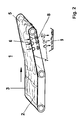
- Figur 2 -
- eine Prinzipdarstellung der erfindungsgemäßen Vorrichtung zum Filtern eine abgeänderte Ausführung.
- FIG. 1 -
- a perspective schematic representation of the device according to the invention for filtering,
- FIG. 2 -
- a schematic diagram of the device according to the invention for filtering a modified version.
In beiden Figuren ist die erfindungsgemäße Vorrichtung 1 zum Filtern, beispielsweise als Vorfilter für eine Filter- und Aufbereitungsanlage für Kühl- bzw. Bearbeitungsmedien, wie von Ölen normaler Viskosität, vorgesehen.
Das zu reinigende Öl, welches in diesem Fall mit feinen Metallteilchen und Schleifscheibenabrieb versetzt ist, wird in dem Bereich 2 auf das Filterband 3 aufgebracht und läuft, der Schwerkraft folgend, durch das Filterband 3 wobei sich ein aus den festen Bestandteilen und Ölresten bestehender Filterkuchen 7 zu bilden beginnt, welcher einen bestimmten Zeitabschnitt noch zunimmt; dann jedoch in einer konstanten Dicke auf dem Filterband 3 anhaftet.In both figures, the
The oil to be cleaned, which in this case is mixed with fine metal particles and grinding wheel abrasion, is applied in the
Bei der Darstellung gemäß
Mit dem Anlegen des Vakuums wird zwangsläufig der Filterkuchen 7 auf dem Filterband 3 verfestigt. Das Filterband 3 wird selbstverständlich bereits in dieser Filtrationsphase mit einer entsprechend gewählten Geschwindigkeit vorwärts bewegt, so daß der Filterkuchen 7 auf dem Filterband 3 abgeführt wird.
Mit dem Überschreiten des Umlenkbereiches 5 werden zunächst die nur locker am Filterband 3 anhaftenden Teile des Filterkuchens 7 vom Filterband 3 in ein vorgesehenes Sammelbehältnis 9 abfallen. Die fest anhaftenden Bestandteile des Filterkuchens 7 werden mit dem Filterband 3 bis in einen Bereich geführt, in welchem eine Luft-Ausblaseinheit 8 angeordnet ist. Hier wird der mit dem Anlegen des Vakuums erzeugte Luftstrom von Innen her durch das Filterband 3 hindurch geführt und die am Filterband 3 noch anhaftenden Bestandteile des Filterkuchens 7 werden vom Filterband 3 abgeblasen und ebenfalls in einem Sammelbehältnis 9 aufgenommen.With the application of the vacuum, the
When the
In vorteilhafter Weise ist die Luft-Ausblaseinheit 8 so ausgeführt, daß diese vollständig über die Breite des Filterbandes 3 reicht und längs dem Filterband 3 verschiebbar ist.Advantageously, the
In einer anderen Ausführung der Vorrichtung 1 zum Filtern gemäß
Nach Überschreiten des Umlenkbereiches 5 werden zunächst nur lockere Teile des Filterkuchens 7 von selbst vom Filterband 3 abfallen. Die verbleibenden, am Filterband 3 fest anhaftenden Bestandteile werden bis in den Bereich der Luft-Ausblaseinheit 8 mitgenommen.After exceeding the
Der über die Luft-Ansaugeinheit 6 angesaugte Luftstrom wird über vorgesehenen Düsenbereiche in der Luft-Ausblaseinheit 8 von Innen her durch das Filterband 3 hindurch geführt, so daß nur mittels dieses Luftstroms die noch am Filterband 3 anhaftenden Bestandteile des Filterkuchens 7 vom Filterband 3 abgeblasen werden. In vorteilhafter Weise kann diese Einheit so ausgeführt sein, daß dieser bei Bedarf weitere Ansaug-Lufteinlässe und/oder Düsenbereiche in der Luft-Ausblaseinheit 8 zugeordnet werden können. Der so vom Filterband 3 entfernte Filterkuchen 7 wird in einem vorgesehenen Sammelbehältnis 9 aufgenommen und nachfolgend einem entsprechenden Aufbereitungs- bzw. Entsorgungsprozeß unterzogen.The air stream sucked in via the
Auf Grund dessen, daß die Entfernung des Filterkuchens 7 vom Filterband 3 ohne jegliche mechanisch wirkenden Maschinenelemente, also im Wesentlichen nur durch das Abblasen von Innen durch das Filterband hindurch erfolgt kann die Dicke des Filterbandes 3 verhältnismäßig klein gehalten werden.Due to the fact that the removal of the
Mittels des Anlegens des Unterdruckes im Bereich 2 des Auftragens des zu reinigenden Öls bzw. des Ansaugen eines Luftstromes im Bereich vor dem Umlenkbereich 5 wird eine größere Durchflußmenge des zu filtrierenden Öls bei einer kleineren Filterfläche realisierbar.By means of applying the negative pressure in the
- 11
- Vorrichtung zum FilternDevice for filtering
- 22
- Bereich des Auftragens der zu filtrierende FlüssigkeitArea of application of the liquid to be filtered
- 33
- Filterbandfilter belt
- 44
- Vakuum-AbsaugbereichVacuum suction
- 55
- Umlenkbereichdeflection
- 66
- Luft-AnsaugeinheitAir-intake unit
- 77
- Filterkuchenfilter cake
- 88th
- Luft-AusblaseinheitAir exhaust unit
- 99
- Sammelbehältnis für FilterkuchenCollecting container for filter cake
Claims (4)
dadurch gekennzeichnet, daß
mindestens in einem ersten Bereich (2), dem Bereich des Auftragens der zu filtrierende Flüssigkeit auf den Filterband-Umlauf, unterhalb des tragenden Filterbandes (3) ein Vakuum-Absaugbereich (4) und eine Luft-Ausblaseinheit (8), mit welcher der Filterkuchen (7) vom Filterband (3) abblasbar ist, angeordnet ist.Apparatus for filtering in the form of a belt filter with an endless filter belt of fabric,
characterized in that
at least in a first area (2), the area of application of the liquid to be filtered on the filter belt circuit, below the supporting filter belt (3), a vacuum suction area (4) and an air blow-out unit (8), with which the filter cake (7) from the filter belt (3) is blown, is arranged.
dadurch gekennzeichnet, daß
nahe des Umlenkbereiches (5), in dem Zwischenraum zwischen dem vorlaufenden und dem rücklaufenden Teil des Filterbandes (3), eine Luft-Ansaugeinheit (6), mit welcher Luft durch den anhaftenden Filterkuchen (7) und das Filterband (3) ansaugbar ist, und eine Luft-Ausblaseinheit (8), mit welcher der Filterkuchen (7) vom Filterband (3) abblasbar ist, angeordnet ist.Apparatus for filtering in the form of a belt filter with an endless filter belt of fabric,
characterized in that
near the deflection region (5), in the intermediate space between the leading and the returning part of the filter belt (3), an air suction unit (6) with which air can be sucked through the adhering filter cake (7) and the filter belt (3), and an air blow-out unit (8), with which the filter cake (7) from the filter belt (3) is blown away, is arranged.
dadurch gekennzeichnet, daß
die Luft-Ansaugeinheit (6) und/oder die Luft-Ausblaseinheit (8) in dem Zwischenraum zwischen dem vorlaufenden und dem rücklaufenden Teil des Filterbandes (3), verschiebbar angeordnet sind.Apparatus for filtering in the form of a belt filter with an endless fabric filter belt according to claim 1 or 2,
characterized in that
the air suction unit (6) and / or the air blower unit (8) are slidably disposed in the space between the leading and the return part of the filter belt (3).
dadurch gekennzeichnet, daß
die Luftein- bzw. -auslässe der Luft-Ansaugeinheit (6) bzw. der Luft-Ausblaseinheit (8) über die Breite des Filterbandes (3) reichend angeordnet sind.Apparatus for filtering in the form of a belt filter with an endless filter belt of fabric,
characterized in that
the air inlets and outlets of the air suction unit (6) and the air blower unit (8) over the width of the filter belt (3) are arranged reaching.
Applications Claiming Priority (1)
| Application Number | Priority Date | Filing Date | Title |
|---|---|---|---|
| DE202007004536U DE202007004536U1 (en) | 2007-03-28 | 2007-03-28 | Belt filter for separation of solids from liquids uses minimal filtration area by provision of vacuum slots below feed area |
Publications (2)
| Publication Number | Publication Date |
|---|---|
| EP1974785A2 true EP1974785A2 (en) | 2008-10-01 |
| EP1974785A3 EP1974785A3 (en) | 2009-03-18 |
Family
ID=38268592
Family Applications (1)
| Application Number | Title | Priority Date | Filing Date |
|---|---|---|---|
| EP08003882A Withdrawn EP1974785A3 (en) | 2007-03-28 | 2008-03-03 | Belt filter |
Country Status (2)
| Country | Link |
|---|---|
| EP (1) | EP1974785A3 (en) |
| DE (1) | DE202007004536U1 (en) |
Cited By (2)
| Publication number | Priority date | Publication date | Assignee | Title |
|---|---|---|---|---|
| CN109442882A (en) * | 2018-10-31 | 2019-03-08 | 广东博昊实业集团有限公司 | A kind of anticlogging environment-friendly type dregs of fat separation equipment of oil refining |
| DE102014000180B4 (en) | 2013-04-02 | 2019-03-14 | Ute SCHLEPPY | Drum filter with band pre-separator |
Families Citing this family (1)
| Publication number | Priority date | Publication date | Assignee | Title |
|---|---|---|---|---|
| GB201003202D0 (en) * | 2010-02-25 | 2010-04-14 | Microbial Solutions Ltd | Method and apparatus for cleaning filters |
Citations (4)
| Publication number | Priority date | Publication date | Assignee | Title |
|---|---|---|---|---|
| DE4418840A1 (en) | 1994-05-30 | 1995-12-07 | Sommermeyer Filtertechnik Gmbh | Endless filter belt passes through low transverse gully with by-pass jet |
| DE4439944A1 (en) | 1994-11-09 | 1996-05-15 | Schloemann Siemag Ag | Belt filter device for removing foreign particles from liquid baths |
| DE29521021U1 (en) | 1994-04-08 | 1996-07-25 | Frankenberger Dieter | Conveyor belt filter device |
| DE19836728B4 (en) | 1998-08-13 | 2004-11-25 | Cae Beyss Gmbh | Vacuum belt filter |
Family Cites Families (5)
| Publication number | Priority date | Publication date | Assignee | Title |
|---|---|---|---|---|
| FR1352960A (en) * | 1963-01-09 | 1964-02-21 | Automatic device for the purification of waste water laden with sticky substances | |
| NL7210541A (en) * | 1972-08-01 | 1974-02-05 | ||
| GB1576819A (en) * | 1976-12-08 | 1980-10-15 | V H Pannevis & Zn Bv Maschf | Method and device for removing a liquid for a mixture of liquid and solid substances |
| DE3707781A1 (en) * | 1987-03-11 | 1988-09-22 | Karl Wiedemann | Apparatus for sludge dehydration |
| DE102005002844A1 (en) * | 2005-01-20 | 2006-07-27 | Knoll Maschinenbau Gmbh | Cleaning device for filter belts |
-
2007
- 2007-03-28 DE DE202007004536U patent/DE202007004536U1/en not_active Expired - Lifetime
-
2008
- 2008-03-03 EP EP08003882A patent/EP1974785A3/en not_active Withdrawn
Patent Citations (4)
| Publication number | Priority date | Publication date | Assignee | Title |
|---|---|---|---|---|
| DE29521021U1 (en) | 1994-04-08 | 1996-07-25 | Frankenberger Dieter | Conveyor belt filter device |
| DE4418840A1 (en) | 1994-05-30 | 1995-12-07 | Sommermeyer Filtertechnik Gmbh | Endless filter belt passes through low transverse gully with by-pass jet |
| DE4439944A1 (en) | 1994-11-09 | 1996-05-15 | Schloemann Siemag Ag | Belt filter device for removing foreign particles from liquid baths |
| DE19836728B4 (en) | 1998-08-13 | 2004-11-25 | Cae Beyss Gmbh | Vacuum belt filter |
Cited By (2)
| Publication number | Priority date | Publication date | Assignee | Title |
|---|---|---|---|---|
| DE102014000180B4 (en) | 2013-04-02 | 2019-03-14 | Ute SCHLEPPY | Drum filter with band pre-separator |
| CN109442882A (en) * | 2018-10-31 | 2019-03-08 | 广东博昊实业集团有限公司 | A kind of anticlogging environment-friendly type dregs of fat separation equipment of oil refining |
Also Published As
| Publication number | Publication date |
|---|---|
| EP1974785A3 (en) | 2009-03-18 |
| DE202007004536U1 (en) | 2007-06-28 |
Similar Documents
| Publication | Publication Date | Title |
|---|---|---|
| EP2283908B1 (en) | Device for processing cooling lubricant | |
| DE2802369A1 (en) | FILTER DEVICE FOR FILTERING AIR POLLUTED BY DUST AND FIBER WASTE | |
| EP0029222B1 (en) | Integrated flotation and filtration device and method for combined flotation and filtration | |
| DE4330233C2 (en) | sweeper | |
| EP1974785A2 (en) | Belt filter | |
| DE3540259C2 (en) | Device for separating from fiber spinning machines, in particular blow room machines and cards, extracted fiber waste and the like. Like impurities | |
| EP3900804B1 (en) | Filter and filter device for filtering an aqueous liquid containing solid particles | |
| DE202016101410U1 (en) | Cooling lubricant device for a machine tool | |
| EP1291059B1 (en) | Device for separation and removal of machining chips | |
| EP0622099B1 (en) | Separating and filtering device for solid/liquid separation, especially with drying aid | |
| DE10331998A1 (en) | Apparatus for filtering contaminated liquids, such as cooling lubricants, in particular from machine tools | |
| EP0432379B1 (en) | Bandfilter device for the purification of processing liquids | |
| DE8135658U1 (en) | VACUUM BAND FILTER | |
| EP2228114A1 (en) | Cleaning assembly | |
| DE4214902C2 (en) | Device for cleaning cooling lubricants | |
| DE4137608C2 (en) | Device for filtering liquids loaded with magnetizable and non-magnetizable solids | |
| DE19813287C2 (en) | Involute belt machine | |
| DE102016104678B4 (en) | Cooling lubricant device for a machine tool | |
| EP0191423B1 (en) | Cleaning machine for dry-cleaning textile articles | |
| EP0603662A1 (en) | Apparatus for continuous washing of soiled, fat-containing wool | |
| DE3224948A1 (en) | Appliance for the smoothing of articles of clothing | |
| DE3734200A1 (en) | Process and device for removing adhering lubricant from workpieces | |
| DE102007025540B3 (en) | Filter device for filtering liquids | |
| DE19537396C1 (en) | Filter band cleansing device for use in a cooling lubricant system | |
| EP0588230A1 (en) | Separation and filtration device for solid-liquid separation |
Legal Events
| Date | Code | Title | Description |
|---|---|---|---|
| PUAI | Public reference made under article 153(3) epc to a published international application that has entered the european phase |
Free format text: ORIGINAL CODE: 0009012 |
|
| AK | Designated contracting states |
Kind code of ref document: A2 Designated state(s): AT BE BG CH CY CZ DE DK EE ES FI FR GB GR HR HU IE IS IT LI LT LU LV MC MT NL NO PL PT RO SE SI SK TR |
|
| AX | Request for extension of the european patent |
Extension state: AL BA MK RS |
|
| PUAL | Search report despatched |
Free format text: ORIGINAL CODE: 0009013 |
|
| AK | Designated contracting states |
Kind code of ref document: A3 Designated state(s): AT BE BG CH CY CZ DE DK EE ES FI FR GB GR HR HU IE IS IT LI LT LU LV MC MT NL NO PL PT RO SE SI SK TR |
|
| AX | Request for extension of the european patent |
Extension state: AL BA MK RS |
|
| AKX | Designation fees paid |
Designated state(s): AT BE BG CH CY CZ DE DK EE ES FI FR GB GR HR HU IE IS IT LI LT LU LV MC MT NL NO PL PT RO SE SI SK TR |
|
| STAA | Information on the status of an ep patent application or granted ep patent |
Free format text: STATUS: THE APPLICATION IS DEEMED TO BE WITHDRAWN |
|
| 18D | Application deemed to be withdrawn |
Effective date: 20090919 |