EP1974700B1 - Stent mit radial expandierbarem Grundkörper - Google Patents
Stent mit radial expandierbarem Grundkörper Download PDFInfo
- Publication number
- EP1974700B1 EP1974700B1 EP08004044.7A EP08004044A EP1974700B1 EP 1974700 B1 EP1974700 B1 EP 1974700B1 EP 08004044 A EP08004044 A EP 08004044A EP 1974700 B1 EP1974700 B1 EP 1974700B1
- Authority
- EP
- European Patent Office
- Prior art keywords
- stent
- marker
- strut
- appendices
- contracted
- Prior art date
- Legal status (The legal status is an assumption and is not a legal conclusion. Google has not performed a legal analysis and makes no representation as to the accuracy of the status listed.)
- Ceased
Links
- 239000003550 marker Substances 0.000 claims description 18
- 229920000642 polymer Polymers 0.000 claims description 8
- 239000011248 coating agent Substances 0.000 claims description 7
- 238000000576 coating method Methods 0.000 claims description 7
- 239000000463 material Substances 0.000 claims description 7
- 239000003381 stabilizer Substances 0.000 description 10
- 238000002788 crimping Methods 0.000 description 3
- 230000002093 peripheral effect Effects 0.000 description 3
- 229910000861 Mg alloy Inorganic materials 0.000 description 2
- 239000000853 adhesive Substances 0.000 description 2
- 230000001070 adhesive effect Effects 0.000 description 2
- 230000008878 coupling Effects 0.000 description 2
- 238000010168 coupling process Methods 0.000 description 2
- 238000005859 coupling reaction Methods 0.000 description 2
- 238000003698 laser cutting Methods 0.000 description 2
- 230000000087 stabilizing effect Effects 0.000 description 2
- FYYHWMGAXLPEAU-UHFFFAOYSA-N Magnesium Chemical compound [Mg] FYYHWMGAXLPEAU-UHFFFAOYSA-N 0.000 description 1
- 208000031481 Pathologic Constriction Diseases 0.000 description 1
- 229910000831 Steel Inorganic materials 0.000 description 1
- 238000004026 adhesive bonding Methods 0.000 description 1
- 210000004204 blood vessel Anatomy 0.000 description 1
- 239000004035 construction material Substances 0.000 description 1
- 230000000916 dilatatory effect Effects 0.000 description 1
- 238000002474 experimental method Methods 0.000 description 1
- 238000010438 heat treatment Methods 0.000 description 1
- 238000002513 implantation Methods 0.000 description 1
- 230000007794 irritation Effects 0.000 description 1
- 229910052749 magnesium Inorganic materials 0.000 description 1
- 239000011777 magnesium Substances 0.000 description 1
- 238000002844 melting Methods 0.000 description 1
- 230000008018 melting Effects 0.000 description 1
- 229910052751 metal Inorganic materials 0.000 description 1
- 239000002184 metal Substances 0.000 description 1
- 238000007363 ring formation reaction Methods 0.000 description 1
- 238000000926 separation method Methods 0.000 description 1
- 239000010959 steel Substances 0.000 description 1
- 230000036262 stenosis Effects 0.000 description 1
- 208000037804 stenosis Diseases 0.000 description 1
- 230000003319 supportive effect Effects 0.000 description 1
- 230000002123 temporal effect Effects 0.000 description 1
- 238000007669 thermal treatment Methods 0.000 description 1
- 230000002792 vascular Effects 0.000 description 1
Images




Classifications
-
- A—HUMAN NECESSITIES
- A61—MEDICAL OR VETERINARY SCIENCE; HYGIENE
- A61F—FILTERS IMPLANTABLE INTO BLOOD VESSELS; PROSTHESES; DEVICES PROVIDING PATENCY TO, OR PREVENTING COLLAPSING OF, TUBULAR STRUCTURES OF THE BODY, e.g. STENTS; ORTHOPAEDIC, NURSING OR CONTRACEPTIVE DEVICES; FOMENTATION; TREATMENT OR PROTECTION OF EYES OR EARS; BANDAGES, DRESSINGS OR ABSORBENT PADS; FIRST-AID KITS
- A61F2/00—Filters implantable into blood vessels; Prostheses, i.e. artificial substitutes or replacements for parts of the body; Appliances for connecting them with the body; Devices providing patency to, or preventing collapsing of, tubular structures of the body, e.g. stents
- A61F2/82—Devices providing patency to, or preventing collapsing of, tubular structures of the body, e.g. stents
- A61F2/86—Stents in a form characterised by the wire-like elements; Stents in the form characterised by a net-like or mesh-like structure
- A61F2/90—Stents in a form characterised by the wire-like elements; Stents in the form characterised by a net-like or mesh-like structure characterised by a net-like or mesh-like structure
- A61F2/91—Stents in a form characterised by the wire-like elements; Stents in the form characterised by a net-like or mesh-like structure characterised by a net-like or mesh-like structure made from perforated sheets or tubes, e.g. perforated by laser cuts or etched holes
-
- A—HUMAN NECESSITIES
- A61—MEDICAL OR VETERINARY SCIENCE; HYGIENE
- A61F—FILTERS IMPLANTABLE INTO BLOOD VESSELS; PROSTHESES; DEVICES PROVIDING PATENCY TO, OR PREVENTING COLLAPSING OF, TUBULAR STRUCTURES OF THE BODY, e.g. STENTS; ORTHOPAEDIC, NURSING OR CONTRACEPTIVE DEVICES; FOMENTATION; TREATMENT OR PROTECTION OF EYES OR EARS; BANDAGES, DRESSINGS OR ABSORBENT PADS; FIRST-AID KITS
- A61F2/00—Filters implantable into blood vessels; Prostheses, i.e. artificial substitutes or replacements for parts of the body; Appliances for connecting them with the body; Devices providing patency to, or preventing collapsing of, tubular structures of the body, e.g. stents
- A61F2/82—Devices providing patency to, or preventing collapsing of, tubular structures of the body, e.g. stents
- A61F2/86—Stents in a form characterised by the wire-like elements; Stents in the form characterised by a net-like or mesh-like structure
- A61F2/90—Stents in a form characterised by the wire-like elements; Stents in the form characterised by a net-like or mesh-like structure characterised by a net-like or mesh-like structure
- A61F2/91—Stents in a form characterised by the wire-like elements; Stents in the form characterised by a net-like or mesh-like structure characterised by a net-like or mesh-like structure made from perforated sheets or tubes, e.g. perforated by laser cuts or etched holes
- A61F2/915—Stents in a form characterised by the wire-like elements; Stents in the form characterised by a net-like or mesh-like structure characterised by a net-like or mesh-like structure made from perforated sheets or tubes, e.g. perforated by laser cuts or etched holes with bands having a meander structure, adjacent bands being connected to each other
-
- A—HUMAN NECESSITIES
- A61—MEDICAL OR VETERINARY SCIENCE; HYGIENE
- A61F—FILTERS IMPLANTABLE INTO BLOOD VESSELS; PROSTHESES; DEVICES PROVIDING PATENCY TO, OR PREVENTING COLLAPSING OF, TUBULAR STRUCTURES OF THE BODY, e.g. STENTS; ORTHOPAEDIC, NURSING OR CONTRACEPTIVE DEVICES; FOMENTATION; TREATMENT OR PROTECTION OF EYES OR EARS; BANDAGES, DRESSINGS OR ABSORBENT PADS; FIRST-AID KITS
- A61F2/00—Filters implantable into blood vessels; Prostheses, i.e. artificial substitutes or replacements for parts of the body; Appliances for connecting them with the body; Devices providing patency to, or preventing collapsing of, tubular structures of the body, e.g. stents
- A61F2/95—Instruments specially adapted for placement or removal of stents or stent-grafts
- A61F2/958—Inflatable balloons for placing stents or stent-grafts
-
- A—HUMAN NECESSITIES
- A61—MEDICAL OR VETERINARY SCIENCE; HYGIENE
- A61F—FILTERS IMPLANTABLE INTO BLOOD VESSELS; PROSTHESES; DEVICES PROVIDING PATENCY TO, OR PREVENTING COLLAPSING OF, TUBULAR STRUCTURES OF THE BODY, e.g. STENTS; ORTHOPAEDIC, NURSING OR CONTRACEPTIVE DEVICES; FOMENTATION; TREATMENT OR PROTECTION OF EYES OR EARS; BANDAGES, DRESSINGS OR ABSORBENT PADS; FIRST-AID KITS
- A61F2/00—Filters implantable into blood vessels; Prostheses, i.e. artificial substitutes or replacements for parts of the body; Appliances for connecting them with the body; Devices providing patency to, or preventing collapsing of, tubular structures of the body, e.g. stents
- A61F2/82—Devices providing patency to, or preventing collapsing of, tubular structures of the body, e.g. stents
- A61F2/86—Stents in a form characterised by the wire-like elements; Stents in the form characterised by a net-like or mesh-like structure
- A61F2/90—Stents in a form characterised by the wire-like elements; Stents in the form characterised by a net-like or mesh-like structure characterised by a net-like or mesh-like structure
- A61F2/91—Stents in a form characterised by the wire-like elements; Stents in the form characterised by a net-like or mesh-like structure characterised by a net-like or mesh-like structure made from perforated sheets or tubes, e.g. perforated by laser cuts or etched holes
- A61F2/915—Stents in a form characterised by the wire-like elements; Stents in the form characterised by a net-like or mesh-like structure characterised by a net-like or mesh-like structure made from perforated sheets or tubes, e.g. perforated by laser cuts or etched holes with bands having a meander structure, adjacent bands being connected to each other
- A61F2002/91533—Stents in a form characterised by the wire-like elements; Stents in the form characterised by a net-like or mesh-like structure characterised by a net-like or mesh-like structure made from perforated sheets or tubes, e.g. perforated by laser cuts or etched holes with bands having a meander structure, adjacent bands being connected to each other characterised by the phase between adjacent bands
-
- A—HUMAN NECESSITIES
- A61—MEDICAL OR VETERINARY SCIENCE; HYGIENE
- A61F—FILTERS IMPLANTABLE INTO BLOOD VESSELS; PROSTHESES; DEVICES PROVIDING PATENCY TO, OR PREVENTING COLLAPSING OF, TUBULAR STRUCTURES OF THE BODY, e.g. STENTS; ORTHOPAEDIC, NURSING OR CONTRACEPTIVE DEVICES; FOMENTATION; TREATMENT OR PROTECTION OF EYES OR EARS; BANDAGES, DRESSINGS OR ABSORBENT PADS; FIRST-AID KITS
- A61F2/00—Filters implantable into blood vessels; Prostheses, i.e. artificial substitutes or replacements for parts of the body; Appliances for connecting them with the body; Devices providing patency to, or preventing collapsing of, tubular structures of the body, e.g. stents
- A61F2/82—Devices providing patency to, or preventing collapsing of, tubular structures of the body, e.g. stents
- A61F2/86—Stents in a form characterised by the wire-like elements; Stents in the form characterised by a net-like or mesh-like structure
- A61F2/90—Stents in a form characterised by the wire-like elements; Stents in the form characterised by a net-like or mesh-like structure characterised by a net-like or mesh-like structure
- A61F2/91—Stents in a form characterised by the wire-like elements; Stents in the form characterised by a net-like or mesh-like structure characterised by a net-like or mesh-like structure made from perforated sheets or tubes, e.g. perforated by laser cuts or etched holes
- A61F2/915—Stents in a form characterised by the wire-like elements; Stents in the form characterised by a net-like or mesh-like structure characterised by a net-like or mesh-like structure made from perforated sheets or tubes, e.g. perforated by laser cuts or etched holes with bands having a meander structure, adjacent bands being connected to each other
- A61F2002/9155—Adjacent bands being connected to each other
- A61F2002/91575—Adjacent bands being connected to each other connected peak to trough
-
- A—HUMAN NECESSITIES
- A61—MEDICAL OR VETERINARY SCIENCE; HYGIENE
- A61F—FILTERS IMPLANTABLE INTO BLOOD VESSELS; PROSTHESES; DEVICES PROVIDING PATENCY TO, OR PREVENTING COLLAPSING OF, TUBULAR STRUCTURES OF THE BODY, e.g. STENTS; ORTHOPAEDIC, NURSING OR CONTRACEPTIVE DEVICES; FOMENTATION; TREATMENT OR PROTECTION OF EYES OR EARS; BANDAGES, DRESSINGS OR ABSORBENT PADS; FIRST-AID KITS
- A61F2/00—Filters implantable into blood vessels; Prostheses, i.e. artificial substitutes or replacements for parts of the body; Appliances for connecting them with the body; Devices providing patency to, or preventing collapsing of, tubular structures of the body, e.g. stents
- A61F2/82—Devices providing patency to, or preventing collapsing of, tubular structures of the body, e.g. stents
- A61F2/86—Stents in a form characterised by the wire-like elements; Stents in the form characterised by a net-like or mesh-like structure
- A61F2/90—Stents in a form characterised by the wire-like elements; Stents in the form characterised by a net-like or mesh-like structure characterised by a net-like or mesh-like structure
- A61F2/91—Stents in a form characterised by the wire-like elements; Stents in the form characterised by a net-like or mesh-like structure characterised by a net-like or mesh-like structure made from perforated sheets or tubes, e.g. perforated by laser cuts or etched holes
- A61F2/915—Stents in a form characterised by the wire-like elements; Stents in the form characterised by a net-like or mesh-like structure characterised by a net-like or mesh-like structure made from perforated sheets or tubes, e.g. perforated by laser cuts or etched holes with bands having a meander structure, adjacent bands being connected to each other
- A61F2002/9155—Adjacent bands being connected to each other
- A61F2002/91591—Locking connectors, e.g. using male-female connections
-
- A—HUMAN NECESSITIES
- A61—MEDICAL OR VETERINARY SCIENCE; HYGIENE
- A61F—FILTERS IMPLANTABLE INTO BLOOD VESSELS; PROSTHESES; DEVICES PROVIDING PATENCY TO, OR PREVENTING COLLAPSING OF, TUBULAR STRUCTURES OF THE BODY, e.g. STENTS; ORTHOPAEDIC, NURSING OR CONTRACEPTIVE DEVICES; FOMENTATION; TREATMENT OR PROTECTION OF EYES OR EARS; BANDAGES, DRESSINGS OR ABSORBENT PADS; FIRST-AID KITS
- A61F2/00—Filters implantable into blood vessels; Prostheses, i.e. artificial substitutes or replacements for parts of the body; Appliances for connecting them with the body; Devices providing patency to, or preventing collapsing of, tubular structures of the body, e.g. stents
- A61F2/95—Instruments specially adapted for placement or removal of stents or stent-grafts
- A61F2002/9505—Instruments specially adapted for placement or removal of stents or stent-grafts having retaining means other than an outer sleeve, e.g. male-female connector between stent and instrument
-
- A—HUMAN NECESSITIES
- A61—MEDICAL OR VETERINARY SCIENCE; HYGIENE
- A61F—FILTERS IMPLANTABLE INTO BLOOD VESSELS; PROSTHESES; DEVICES PROVIDING PATENCY TO, OR PREVENTING COLLAPSING OF, TUBULAR STRUCTURES OF THE BODY, e.g. STENTS; ORTHOPAEDIC, NURSING OR CONTRACEPTIVE DEVICES; FOMENTATION; TREATMENT OR PROTECTION OF EYES OR EARS; BANDAGES, DRESSINGS OR ABSORBENT PADS; FIRST-AID KITS
- A61F2230/00—Geometry of prostheses classified in groups A61F2/00 - A61F2/26 or A61F2/82 or A61F9/00 or A61F11/00 or subgroups thereof
- A61F2230/0002—Two-dimensional shapes, e.g. cross-sections
- A61F2230/0004—Rounded shapes, e.g. with rounded corners
- A61F2230/0013—Horseshoe-shaped, e.g. crescent-shaped, C-shaped, U-shaped
-
- A—HUMAN NECESSITIES
- A61—MEDICAL OR VETERINARY SCIENCE; HYGIENE
- A61F—FILTERS IMPLANTABLE INTO BLOOD VESSELS; PROSTHESES; DEVICES PROVIDING PATENCY TO, OR PREVENTING COLLAPSING OF, TUBULAR STRUCTURES OF THE BODY, e.g. STENTS; ORTHOPAEDIC, NURSING OR CONTRACEPTIVE DEVICES; FOMENTATION; TREATMENT OR PROTECTION OF EYES OR EARS; BANDAGES, DRESSINGS OR ABSORBENT PADS; FIRST-AID KITS
- A61F2250/00—Special features of prostheses classified in groups A61F2/00 - A61F2/26 or A61F2/82 or A61F9/00 or A61F11/00 or subgroups thereof
- A61F2250/0058—Additional features; Implant or prostheses properties not otherwise provided for
- A61F2250/0071—Additional features; Implant or prostheses properties not otherwise provided for breakable or frangible
-
- A—HUMAN NECESSITIES
- A61—MEDICAL OR VETERINARY SCIENCE; HYGIENE
- A61F—FILTERS IMPLANTABLE INTO BLOOD VESSELS; PROSTHESES; DEVICES PROVIDING PATENCY TO, OR PREVENTING COLLAPSING OF, TUBULAR STRUCTURES OF THE BODY, e.g. STENTS; ORTHOPAEDIC, NURSING OR CONTRACEPTIVE DEVICES; FOMENTATION; TREATMENT OR PROTECTION OF EYES OR EARS; BANDAGES, DRESSINGS OR ABSORBENT PADS; FIRST-AID KITS
- A61F2250/00—Special features of prostheses classified in groups A61F2/00 - A61F2/26 or A61F2/82 or A61F9/00 or A61F11/00 or subgroups thereof
- A61F2250/0058—Additional features; Implant or prostheses properties not otherwise provided for
- A61F2250/0096—Markers and sensors for detecting a position or changes of a position of an implant, e.g. RF sensors, ultrasound markers
- A61F2250/0098—Markers and sensors for detecting a position or changes of a position of an implant, e.g. RF sensors, ultrasound markers radio-opaque, e.g. radio-opaque markers
Definitions
- the invention relates to a stent with the features specified in the preamble of claim.
- Such a vascular graft is in the WO 2004/103 215 A1 described in detail, in particular with regard to the basic areas of application of such stents and their particular problems such as the use of materials with a low elongation at break and lower strength, such as magnesium alloys.
- removable stent is realized by a cylindrical shape, from a contracted starting position in a dilated support position radially expandable body, on the one hand comprises a plurality of circumferentially circumferential, juxtaposed support segments in the axial direction. These are each formed by a contracted in its initial position in coarse structure meandering strut with alternating counter-rotating Guranderbögen of flexible material.
- the main body in axial-parallel direction extending axial connector, which connect the support segments between zenith points of at least a portion of the meandering arcs.
- a supportive prosthesis is described for vessels or intracorporeal lumens having a plurality of support rings connected in a longitudinal direction by means of non-metallic fasteners.
- the above-mentioned magnesium alloys as a material for producing stents have considerably lower strength values than conventional construction materials for balloon expandable stents, such as medical grade 316L, MP35N or L605 steel. These lower strength values cause problems in the practical use of the stents.
- the stent structured from a sleeve material for example by laser cutting, is crimped into its contracted initial position on the balloon catheter.
- the stent is also guided on the catheter system through curved regions of the introducer or blood vessel system.
- individual struts of the stent may open, reducing the holding forces of the stent on the catheter. This causes a considerable risk for a loss of the stent.
- the invention has for its object to improve a stent of the generic type so that unintentional expansion of the stent total or exposed areas, such as the terminal end edges, during implantation is reliably prevented.
- these stabilizing means secure a radial locking of the stent in its crimped state, so that unintentional stretching of the stent is avoided in some areas due to this fixation.
- these stabilizing agents can be realized in different ways, such as by separable ones
- the Fig. 1 makes the structure of a stent in its contracted starting position clear.
- the stent is machined out of a cylindrical metal body by laser cutting in such a way that it has a plurality of supporting segments 1 running around in the circumferential direction U in the axial direction A, which are each formed by a meander-shaped strut 2 in their coarse structure in the contracted initial position shown.
- the support segments 1 are connected to each other by axial connectors 4, each extending between the zenith points 5 to be connected Guranderbögen 3. Due to the offset of the adjacent support segments 1 in the circumferential direction U, the axial connectors 4 always extend from the outside of a meandering bend 3 to the inside of the meandering bend 3 of the adjacent strut 2.
- a bond 6 is provided, which may be detracted, for example, between the two terminal Guranderbögen 3 at diametrically opposite radial positions in the form of a Vergusscons.
- this bond 6 is shown schematically. In this type of bond 6, the adhesive surfaces are loaded on train.
- the individual points of bonding 6 can not only be terminal, as in Fig. 1 to 3 but also be distributed over the length of the stent 1 distributed on the circumference.
- the fixation according to the holding force is resolved automatically in temporal succession in the radial expansion of the stent.
- the stent can be opened homogeneously, provided that the fixing force is only so great that the axial connector 4 can still accommodate them.
- the axial connectors 4 can otherwise act on the bond 6' from both sides, which benefits a homogeneous opening behavior.
- the outermost strut 2 should either be as short as possible or in the following on the basis of FIGS. 7 and 8 Having fine structures described in more detail at the edge to suppress a flaring.
- Fig. 4 shows an alternative possibility for the stabilizing means for additional radial fixation of the stent.
- the stent is held together at its edge, so that the aforementioned "flaring" is prevented.
- the latching between the elements 7, 8 is broken and the stent can open homogeneously.
- FIG. 4 Furthermore, an alternative arrangement of latching elements in the form of hook projections 9, 10 in the interior of a meandering bend 3 is shown by dashed lines. Also, this fixation is produced during crimping by hooking the projections 9, 10 and broken upon expansion of the stent. It can be seen that the hook projections 9, 10 can be provided on any struts 2 along the stent.
- FIGS. 5 and 6 show further variants of the stabilizing agent for additional radial fixation of the stent in the crimped state.
- integrally formed on the peripheral struts 2 Fixiertraversen 11 are provided, which connect two adjacent Switzerlandbögen 3 a strut 2 from zenith 5 to Zenit Vietnamese 5. While in Fig. 5 only one Fixiertraverse 11 is provided in accordance with the embodiment Fig. 6 the edge of the stent is completely completed with a series of fixation traverses 11.
- Each Fixiertraverse 11 has a double-arc shape with a central bend 12 which acts as a predetermined breaking point in the radial expansion of the stent.
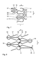
- FIGS. 7 and 8 Another embodiment of the inventively provided stabilizing agent is in the FIGS. 7 and 8 shown.
- This fine-structure strut 14 is formed in each case from two essentially parallel struts 16, 17 with coupling struts 18 extending in the axial direction.
- the basic configuration of the fine-structure strut 14 is therefore ladder-like, the double struts 16, 17 being folded in a zig-zag shape in the jacket plane of the stent.
- arcuate gusset points 19 are formed in the double struts 16, 17, over which the coupling struts 18 are materially secured with respect to the radial expansion of the fine structure strut 14 on the struts 16, 17 in one piece.
- the arch shape in these gusset points 19 improves the expandability of the fine-structure strut 14.
- the fine-structure strut 14 is additionally fixed in the region of the inner gusset points 19 adjacent to one another in the contracted starting position, for example by a gluing 6 or latching means not shown here.
- the entire stent is stabilized at its front edge in the crimped configuration so that a flaring is kept as low as possible.
- the opening forces act on both sides of this fixation, so that higher fixing forces can be overcome without unduly distorting the stent structure.
- extension struts 20 which extend essentially in the axial direction A and are connected at one end via a predetermined breaking point 21 on the outer strut 2 to the stent.
- the free end 22 of the extension struts 20 is in each case at an in Fig. 9 only schematically indicated balloon catheter 23 permanently secured in a suitable manner.
- the extension struts 21 in turn counteract a radial expansion, in particular of the meandering arches 3 of the outer strut 2, whereby a flaring is prevented.
- the predetermined breaking points 21 are separated and the stent thus released from the extension struts 20.
- FIGS. 11 and 12 shown embodiments of stabilizers against a flaring often used in stents x-ray marker extensions 24, which are formed as loop-shaped extensions of the meandering arches 3 of the outer strut 2 and provided with a thermoplastically deformable marker polymer coating 25.
- the x-ray marker extensions 24 are designed with their marker polymer coating 25 so that they touch after crimping the stent and by a thermal treatment of the marker polymer coating 25 to a reshape circumferential ring.
- the ring formation is supported by protruding in the peripheral direction of the x-ray marker extensions 24 cross-connection elements 26, which can be designed in plan view either I- or T-shaped.
- stents with polymer-coated x-ray marker extensions 24 against a flaring such that a peripheral ring, for example made of magnesium, is pushed onto the extensions 24 with their coating 25, by heating and briefly melting the marker polymer coating 25 therein embedded and thus fixed.
- the ring 27 can be made of rigid material or even wire, and also be placed only on a partial circumferential length around the stent.
Landscapes
- Health & Medical Sciences (AREA)
- Engineering & Computer Science (AREA)
- Biomedical Technology (AREA)
- Heart & Thoracic Surgery (AREA)
- Optics & Photonics (AREA)
- Cardiology (AREA)
- Oral & Maxillofacial Surgery (AREA)
- Transplantation (AREA)
- Physics & Mathematics (AREA)
- Vascular Medicine (AREA)
- Life Sciences & Earth Sciences (AREA)
- Animal Behavior & Ethology (AREA)
- General Health & Medical Sciences (AREA)
- Public Health (AREA)
- Veterinary Medicine (AREA)
- Media Introduction/Drainage Providing Device (AREA)
Description
- Die Erfindung betrifft einen Stent mit den im Oberbegriff des Patentanspruches angegebenen Merkmalen.
- Ein derartiges Gefäßimplantat ist in der
WO 2004/103 215 A1 ausführlich beschrieben, insbesondere im Hinblick auf die grundsätzlichen Anwendungsgebiete solcher Stents und deren besondere Problematik etwa beim Einsatz von Materialien mit einer geringen Bruchdehnung und auch geringeren Festigkeiten, wie beispielsweise Magnesiumlegierungen. - Bei der dieser Druckschrift entnehmbaren Ausführungsform ist der Stent durch einen eine Zylinderform umschreibende, aus einer kontrahierten Ausgangsstellung in eine dilatierte Stützstellung radial expandierbaren Grundkörper realisiert, der einerseits eine Vielzahl in Umfangsrichtung umlaufende, in axialer Richtung aneinandergereihte Tragsegmente umfasst. Diese sind jeweils durch eine in ihrer kontrahierten Ausgangsstellung in Grobstruktur mäanderförmige Strebe mit alternierend gegenläufigen Mäanderbögen aus biegsamem Material gebildet. Andererseits weist der Grundkörper in axialparalleler Richtung verlaufende Axialverbinder auf, die die Tragsegmente zwischen Zenitpunkten zumindest eines Teils der Mäanderbögen verbinden.
- In der Druckschrift
WO 2006/029617 A1 ist eine Stützprothese für Gefäße oder intrakorporale Lumina bechrieben, die eine Vielzahl von Stützringen aufweist, die in eine Längsrichtung mit Hilfe von nichtmetallischen Verbindungselementen verbunden sind. - Die Druckschrift
US 5,741,327 offenbart radioopake Marker-Elemente, die an den Enden eines radial expandierbaren Stents angebracht sind. - Die oben erwähnten Magnesiumlegierungen als Material zur Herstellung von Stents besitzen erheblich geringere Festigkeitswerte, als übliche Konstruktionswerkstoffe für ballonexpandierbare Stents, wie beispielsweise medizinischer Stahl mit den Werkstoffbezeichnungen 316L, MP35N oder L605. Diese geringeren Festigkeitswerte bringen in der praktischen Anwendung der Stents Probleme mit sich. So ist es für die Stentplatzierung erforderlich, den Stent auf einem Ballonkatheter zu montieren. Dazu wird der aus einem Hülsenmaterial beispielsweise durch Laserschneiden strukturierte Stent in seine kontrahierte Ausgangsstellung auf den Ballonkatheter gecrimpt. In diesem Zustand wird beim Implantieren der Stent auf dem Kathetersystem auch durch gekrümmte Bereiche des Einführ- oder Blutgefäßsystems geführt. Bei den entsprechenden Passagen können sich einzelne Streben des Stents öffnen, wodurch die Haltekräfte des Stents auf dem Katheter reduziert werden. Dies bedingt ein erhebliches Risiko für einen Verlust des Stents.
- Besonders gefährdete Bereiche des Stents sind die endständigen Strebenelemente mit ihren Mäanderbögen. Durch abstehende Randsegmente - das so genannte "Flaring" - besteht zusätzlich die Gefahr, dass neben der mechanischen Reizung der inneren Gefäßwand beim Passieren der Stenose oder dem Zurückziehen in den Einführkatheter ein unbeabsichtigtes Abstreifen des Stents vom Ballonkatheter erfolgt.
- Ausgehend von der geschilderten Problematik liegt der Erfindung die Aufgabe zugrunde, einen Stent der gattungsgemäßen Art so zu verbessern, dass ein unbeabsichtigtes Aufweiten des Stents insgesamt oder exponierter Bereiche, wie der endständigen Stirnkanten, während des Implantierens zuverlässig verhindert wird.
- Diese Aufgabe wird erfindungsgemäß durch die im Kennzeichnungsteil des Anspruches 1 angegebenen Merkmale gelöst, wonach Mittel zur Stabilisierung der Streben-Grobstruktur in ihrer kontrahierten Ausgangsstellung gegen ein radiales Aufweiten in das Stent-Design integriert sind. Diese Stabilisierungsmittel sind dann bei der eigentlichen radialen Expansion des Stents selbsttätig lösbar.
- Mit Vorteil sichern diese Stabilisierungsmittel eine radiale Arretierung des Stents in seinem gecrimpten Zustand, sodass aufgrund dieser Fixierung ein unbeabsichtigtes Dehnen des Stents auch in Teilbereichen vermieden wird.
- Gemäß bevorzugten Ausführungsformen der Erfindung können diese Stabilisierungsmittel auf unterschiedliche Weise realisiert werden, wie beispielsweise durch auftrennbare
- Verklebungen zwischen benachbart liegenden Mäanderbögen einer Strebe oder von Strebe zu Strebe, durch Rastelemente in der Stent-Struktur, randseitige Fixiertraversen oder Feinstrukturverstrebungen gegen das erwähnte "Flaring". Nähere Erläuterungen hierzu sind der nachfolgenden Beschreibung entnehmbar, in der Ausführungsbeispiele des Erfindungsgegenstandes anhand der beigefügten Zeichnungen näher erläutert werden. Es zeigen:
- Fig. 1
- eine perspektivische Darstellung eines Stents in seiner kontrahierten Ausgangsstellung mit einer endständigen Verklebung als Stabilisierungsmittel,
- Fig. 2 und 3
- Detaildraufsichten auf den Stent in abgewickelter Darstellung mit zwei unterschiedlichen Verklebungsvarianten,
- Fig. 4
- einen schematischen Detailausschnitt in abgewickelter Darstellung eines Stents mit Verrastungen als Stabilisierungsmittel,
- Fig. 5 und 6
- schematische Detailausschnitte in abgewickelter Darstellung von Stents mit randseitigen Fixiertraversen,
- Fig. 7
- eine schematische Detailansicht in abgewickelter Darstellung eines Stents mit randseitigen Feinstrukturverstrebungen als Stabilisierungsmittel,
- Fig. 8
- eine vergrößerten Detailausschnitt aus
Fig. 7 , - Fig. 9
- eine perspektivische Teildarstellung eines Stents mit Verlängerungsstreben zur lösbaren Befestigung an einem Ballonkatheter,
- Fig. 10
- eine Draufsicht auf den Stent gemäß
Fig. 9 in abgewickelter Darstellung, - Fig. 11
- eine Detaildraufsicht auf einen Stent in abgewickelter Darstellung mit aneinander gekoppelten Markerfortsätzen, und
- Fig. 12
- eine Detaildraufsicht eines Stents in abgewickelter Darstellung mit ringgekoppelten Markerfortsätzen.
- Die
Fig. 1 macht die Struktur eines Stents in seiner kontrahierten Ausgangsstellung klar. Der Stent ist aus einem zylindrischen Metallkörper durch Laserschneiden so herausgearbeitet, dass er eine Vielzahl in Umfangsrichtung U umlaufender, in Axialrichtung A aneinandergereihter Tragsegmente 1 aufweist, die jeweils durch eine in der gezeigten kontrahierten Ausgangsstellung in ihrer Grobstruktur mäanderförmige Strebe 2 gebildet sind. - In zur Axialrichtung A paralleler Richtung sind die Tragsegmente 1 durch Axialverbinder 4 miteinander verbunden, die jeweils zwischen den Zenitpunkten 5 jeweils zu verbindender Mäanderbögen 3 verlaufen. Durch den Versatz der benachbarten Tragsegmente 1 in Umfangsrichtung U verlaufen die Axialverbinder 4 immer von der Außenseite eines Mäanderbogens 3 zur Innenseite des Mäanderbogens 3 der benachbarten Strebe 2.
- Wie in den Zeichnungen nicht näher dargestellt wird, werden beim radialen Expandieren des Stents die zwischen den Zenitpunkten 5 verlaufenden Abschnitte der Mäanderbögen 3 in Umfangsrichtung U aufgestellt. Je näher sich die entsprechenden Abschnitte dabei an die Umfangsrichtung U annähern, desto größer ist der so genannte Kollapsdruck des Stents.
- Um die gemäß der Erfindungsaufgabe erwünschte zusätzliche radiale Fixierung des Stents zu erreichen, ist bei der in
Fig. 1 bis 3 gezeigten Variante eine Verklebung 6 vorgesehen, die beispielsweise zwischen den beiden endständigen Mäanderbögen 3 an diametral gegenüberliegenden Radialpositionen in Form eines Vergusspunktes abgebracht sein kann. InFig. 2 ist diese Verklebung 6 schematisch dargestellt. Bei dieser Art von Verklebung 6 werden die Klebeflächen auf Zug belastet. - Alternativ dazu ist es auch möglich, die Verklebung 6 so anzubringen, dass die Klebeflächen auf Scherung belastet werden, wie dies
Fig. 3 andeutet. - Die einzelnen Punkte der Verklebung 6 können nicht nur endständig, wie in
Fig. 1 bis 3 gezeigt, sondern auch über die Länge des Stents 1 verteilt am Umfang angeordnet sein. Bei einer solchen Mehrfachanordnung wird beim radialen Expandieren des Stents die Fixierung entsprechend der Haltekraft in zeitlicher Aufeinanderfolge selbsttätig gelöst. Versuche haben dabei gezeigt, dass trotz einer asymmetrischen Lösung der einzelnen Fixierungen sich der Stent homogen öffnen lässt, sofern die Fixierkraft nur so groß ist, dass die Axialverbinder 4 diese noch aufzunehmen vermögen. Bei einer Anordnung beispielsweise von Verklebungen 6' im Bereich der jeweils zweitäußersten Strebe 2 können die Axialverbinder 4 im Übrigen von beiden Seiten auf die Verklebung 6' einwirken, was einem homogenen Öffnungsverhalten zugute kommt. In diesem Falle sollte die äußerste Strebe 2 entweder möglichst kurz sein oder die im Folgenden anhand derFig. 7 und 8 noch näher beschriebenen Feinstrukturen am Rand aufweisen, um ein Flaring zu unterdrücken. -
Fig. 4 zeigt eine alternative Möglichkeit für das Stabilisierungsmittel zur zusätzlichen radialen Fixierung des Stents. Dort sind zwei benachbarte Mäanderbögen 3 einer Strebe 2 randseitig durch hakenförmige Rastelemente 7, 8 in der kontrahierten Ausgangsstellung miteinander gekoppelt. Dies erfolgt, indem beim Überführen des Stents in seine kontrahierte Ausgangsstellung - dem so genannten Crimpen - die Rastelemente 7, 8 miteinander in Eingriff gebracht werden. Somit ist der Stent an seinem Rand zusammengehalten, sodass dem eingangs erwähnten "Flaring" vorgebeugt wird. Beim radialen Aufweiten wird die Verrastung zwischen den Elementen 7, 8 aufgebrochen und der Stent kann sich homogen öffnen. - In
Fig. 4 ist ferner strichliert eine alternative Anordnung von Rastelementen in Form von Hakenvorsprüngen 9, 10 im Inneren eines Mäanderbogens 3 dargestellt. Auch diese Fixierung wird beim Crimpen durch Einhaken der Vorsprünge 9, 10 hergestellt und beim Expandieren des Stents aufgebrochen. Es ist erkennbar, dass die Hakenvorsprünge 9, 10 an beliebigen Streben 2 entlang des Stents vorgesehen werden können. - Die
Fig. 5 und 6 zeigen weitere Varianten für die Stabilisierungsmittel zur zusätzlichen radialen Fixierung des Stents im gecrimpten Zustand. In dieser Ausführungsform sind einstückig an die randseitigen Streben 2 angeformte Fixiertraversen 11 vorgesehen, die zwei benachbarte Mäanderbögen 3 einer Strebe 2 von Zenitpunkt 5 zu Zenitpunkt 5 verbinden. Während inFig. 5 lediglich eine Fixiertraverse 11 vorgesehen ist, ist bei der Ausführungsform gemäßFig. 6 der Rand des Stents komplett mit einer Reihe von Fixiertraversen 11 abgeschlossen. - Jede Fixiertraverse 11 weist einen doppelbogenförmigen Verlauf mit einem zentralen Knick 12 auf, der als Sollbruchstelle beim radialen Expandieren des Stents wirkt. Durch das Auftrennen der Fixiertraversen 11 kann sich der Stent - wie bereits im Zusammenhang mit der Verklebung 6 geschildert - homogen aufweiten.
- Eine weitere Ausführungsform für die erfindungsgemäß vorgesehenen Stabilisierungsmittel ist in den
Fig. 7 und 8 gezeigt. Es handelt sich dabei um eine randseitig an den Enden 13 des Stents umlaufende Feinstrukturverstrebung 14, die an die Außenseiten 15 der Mäanderbögen 3 angebunden ist. Diese Feinstrukturverstrebung 14 ist jeweils aus zwei im Wesentlichen parallel verlaufenden Streben 16, 17 mit in Axialrichtung verlaufenden Koppelstreben 18 gebildet. Die Grundkonfiguration der Feinstrukturverstrebung 14 ist also leiterartig, wobei die Doppelstreben 16, 17 in der Mantelebene des Stents zick-zack-förmig gefaltet sind. In den Knickpunkten sind dabei bogenförmige Zwickelpunkte 19 in die Doppelstreben 16, 17 eingeformt, über die die Koppelstreben 18 materialschonend hinsichtlich des radialen Aufweitens der Feinstrukturverstrebung 14 an den Streben 16, 17 einstückig befestigt sind. Durch die Bogenform in diesen Zwickelpunkten 19 wird die Aufdehnbarkeit der Feinstrukturverstrebung 14 verbessert. - Wie in
Fig. 8 schematisch angedeutet ist, ist die Feinstrukturverstrebung 14 im Bereich der in der kontrahierten Ausgangsstellung einander benachbarten, inneren Zwickelpunkte 19 aneinander beispielsweise durch eine Verklebung 6 oder auch hier nicht dargestellte Rastmittel zusätzlich fixiert. Damit ist der gesamte Stent an seinem stirnseitigen Rand in der vercrimpten Konfiguration so stabilisiert, dass ein Flaring möglichst gering gehalten wird. Durch die Fixierung bei den innen liegenden Zwickelpunkten 19 wirken die Öffnungskräfte beidseitig dieser Fixierung, sodass höhere Fixierkräfte überwunden werden können, ohne die Stentstruktur unzulässig zu verziehen. - Anhand der
Fig. 9 und10 ist eine weitere Alternative für das Stabilisierungsmittel zur zusätzlichen radialen Fixierung des Stents dargestellt. Es handelt sich hierbei um Verlängerungsstreben 20, die im Wesentlichen in Axialrichtung A verlaufen und mit ihrem einen Ende über eine Sollbruchstelle 21 an der äußeren Strebe 2 an den Stent angebunden sind. Das freie Ende 22 der Verlängerungsstreben 20 ist jeweils an einem inFig. 9 nur schematisch angedeuteten Ballonkatheter 23 in geeigneter Weise dauerhaft befestigt. - Die Verlängerungsstreben 21 wirken wiederum einer radialen Expansion insbesondere der Mäanderbögen 3 der äußeren Strebe 2 entgegen, wodurch ein Flaring unterbunden wird. Beim Dilatieren des Stents werden die Sollbruchstellen 21 aufgetrennt und der Stent damit von den Verlängerungsstreben 20 freigegeben.
- Die in den
Fig. 11 und 12 gezeigten Ausführungsbeispiele für Stabilisierungsmittel gegen eine Flaring nützen die bei Stents oftmals vorhandenen Röntgenmarker-Fortsätze 24, die als ösenförmige Fortsätze an die Mäanderbögen 3 der äußeren Strebe 2 angeformt und mit einer thermoplastisch umformbaren Markerpolymerbeschichtung 25 versehen sind. Um diese bei Stents bekannten Elemente als Stabilisierungsmittel gegen ein Flaring zu verwenden, sind die Röntgenmarker-Fortsätze 24 mit ihrer Marker-Polymerbeschichtung 25 so ausgelegt, dass sie sich nach dem Krimpen des Stents berühren und durch eine thermische Behandlung der Marker-Polymerbeschichtung 25 zu einer umlaufenden Ring umformen. Die Ringbildung wird dabei durch in Peripherrichtung von den Röntgenmarker-Fortsätzen 24 abstehende Querverbindungselemente 26 unterstützt, die in Draufsicht entweder I- oder T-förmig gestaltet sein können. - Schließlich ist es - wie in
Fig. 12 gezeigt ist - noch möglich, Stents mit polymerbeschichteten Röntgenmarker-Fortsätzen 24 so gegen ein Flaring auszurüsten, dass auf die Fortsätze 24 mit ihrer Beschichtung 25 ein umlaufender Ring beispielsweise aus Magnesium aufgeschoben ist, der durch ein Erwärmen und kurzes Aufschmelzen der Marker-Polymerbeschichtung 25 darin eingebettet und somit fixiert wird. Der Ring 27 kann aus steifem Material oder auch Draht bestehen, und auch nur auf einer Teil-Umfangslänge um den Stent gelegt sein.
Claims (3)
- Stent, insbesondere aus einem Material mit einer geringen Festigkeit, mit einem eine Zylinderform umschreibenden, aus einer kontrahierten Ausgangsstellung in eine dilatierte Stützstellung radial expandierbaren Grundkörper umfassend- eine Vielzahl in Umfangsrichtung (U) umlaufender, in Axialrichtung (A) aneinandergereihter Tragsegmente (1), die jeweils durch eine in ihrer kontrahierten Ausgangsstellung in ihrer Grobstruktur mäanderförmige Strebe (2) mit alternierend gegenläufigen, in die Stützstellung expandierbaren Mäanderbögen (3) aus biegsamen Material gebildet sind, und- in axialparalleler Richtung (A) die Tragsegmente (1) vorzugsweise zwischen Zenitpunkten (5) zumindest eines Teils der Mäanderbögen (3) verbindende Axialverbinder (4), und- - Röntgenmarker-Fortsätze (24) an den randseitigen Streben (2) zur Stabilisierung der Streben-Grobstruktur in ihrer kontrahierten Ausgangsstellung gegen ein radiales Aufweiten,dadurch gekennzeichnet, dass die Röntgenmarker-Fortsätze (24)- markerpolymerbeschichtet sind,- durch die Markerpolymerbeschichtung (25) im kontrahierten Zustand ringförmig gekoppelt sind und- bei einer radialen Expansion des Stents selbsttätig lösbar sind.
- Stent nach Anspruch 1, dadurch gekennzeichnet, dass die Röntgenmarker-Fortsätze (24) mit radial gerichteten Querverbindungselementen (26) versehen sind.
- Stent nach einem der Ansprüche 1 - 2 , dadurch gekennzeichnet, dass auf die Röntgenmarker-Fortsätze (24) im kontrahierten Stent-Zustand ein in die Markerpolymerbeschichtung (25) eingebetteter Ring (27), vorzugsweise Drahtring aufgezogen ist.
Applications Claiming Priority (1)
| Application Number | Priority Date | Filing Date | Title |
|---|---|---|---|
| DE200710015670 DE102007015670A1 (de) | 2007-03-31 | 2007-03-31 | Stent mit radial expandierbarem Grundkörper |
Publications (2)
| Publication Number | Publication Date |
|---|---|
| EP1974700A1 EP1974700A1 (de) | 2008-10-01 |
| EP1974700B1 true EP1974700B1 (de) | 2013-05-22 |
Family
ID=39456395
Family Applications (1)
| Application Number | Title | Priority Date | Filing Date |
|---|---|---|---|
| EP08004044.7A Ceased EP1974700B1 (de) | 2007-03-31 | 2008-03-05 | Stent mit radial expandierbarem Grundkörper |
Country Status (3)
| Country | Link |
|---|---|
| US (2) | US20080243230A1 (de) |
| EP (1) | EP1974700B1 (de) |
| DE (1) | DE102007015670A1 (de) |
Families Citing this family (36)
| Publication number | Priority date | Publication date | Assignee | Title |
|---|---|---|---|---|
| AU2002345328A1 (en) | 2001-06-27 | 2003-03-03 | Remon Medical Technologies Ltd. | Method and device for electrochemical formation of therapeutic species in vivo |
| KR100511618B1 (ko) * | 2005-01-17 | 2005-08-31 | 이경범 | 약물방출 조절형 다층 코팅 스텐트 및 이의 제조방법 |
| US8840660B2 (en) | 2006-01-05 | 2014-09-23 | Boston Scientific Scimed, Inc. | Bioerodible endoprostheses and methods of making the same |
| US8089029B2 (en) | 2006-02-01 | 2012-01-03 | Boston Scientific Scimed, Inc. | Bioabsorbable metal medical device and method of manufacture |
| US8048150B2 (en) | 2006-04-12 | 2011-11-01 | Boston Scientific Scimed, Inc. | Endoprosthesis having a fiber meshwork disposed thereon |
| JP2009545407A (ja) | 2006-08-02 | 2009-12-24 | ボストン サイエンティフィック サイムド,インコーポレイテッド | 三次元分解制御を備えたエンドプロテーゼ |
| JP2010503494A (ja) | 2006-09-15 | 2010-02-04 | ボストン サイエンティフィック リミテッド | 生分解性内部人工器官およびその製造方法 |
| WO2008034031A2 (en) | 2006-09-15 | 2008-03-20 | Boston Scientific Limited | Bioerodible endoprostheses and methods of making the same |
| EP2210625B8 (de) | 2006-09-15 | 2012-02-29 | Boston Scientific Scimed, Inc. | Biologisch erodierbare Endoprothese mit biostabilen anorganischen Schichten |
| US8052744B2 (en) | 2006-09-15 | 2011-11-08 | Boston Scientific Scimed, Inc. | Medical devices and methods of making the same |
| JP2010503482A (ja) | 2006-09-18 | 2010-02-04 | ボストン サイエンティフィック リミテッド | 内部人工器官 |
| EP2125065B1 (de) | 2006-12-28 | 2010-11-17 | Boston Scientific Limited | Bioerodierbare endoprothesen und herstellungsverfahren dafür |
| DE102007025921A1 (de) * | 2007-06-02 | 2008-12-04 | Biotronik Vi Patent Ag | Medizinisches Implantat, insbesondere Stent |
| US8052745B2 (en) | 2007-09-13 | 2011-11-08 | Boston Scientific Scimed, Inc. | Endoprosthesis |
| US8128677B2 (en) | 2007-12-12 | 2012-03-06 | Intact Vascular LLC | Device and method for tacking plaque to a blood vessel wall |
| US7998192B2 (en) | 2008-05-09 | 2011-08-16 | Boston Scientific Scimed, Inc. | Endoprostheses |
| US8236046B2 (en) | 2008-06-10 | 2012-08-07 | Boston Scientific Scimed, Inc. | Bioerodible endoprosthesis |
| US7985252B2 (en) | 2008-07-30 | 2011-07-26 | Boston Scientific Scimed, Inc. | Bioerodible endoprosthesis |
| US8382824B2 (en) | 2008-10-03 | 2013-02-26 | Boston Scientific Scimed, Inc. | Medical implant having NANO-crystal grains with barrier layers of metal nitrides or fluorides |
| WO2010101901A2 (en) | 2009-03-02 | 2010-09-10 | Boston Scientific Scimed, Inc. | Self-buffering medical implants |
| US8435281B2 (en) | 2009-04-10 | 2013-05-07 | Boston Scientific Scimed, Inc. | Bioerodible, implantable medical devices incorporating supersaturated magnesium alloys |
| WO2011119573A1 (en) | 2010-03-23 | 2011-09-29 | Boston Scientific Scimed, Inc. | Surface treated bioerodible metal endoprostheses |
| JP2013529507A (ja) | 2010-06-21 | 2013-07-22 | ゾリオン メディカル インコーポレイテッド | 生体吸収性インプラント |
| US8986369B2 (en) | 2010-12-01 | 2015-03-24 | Zorion Medical, Inc. | Magnesium-based absorbable implants |
| WO2014134111A1 (en) * | 2013-02-28 | 2014-09-04 | Boston Scientific Scimed, Inc. | Implantable medical devices for reduced tissue inflammation |
| US9717609B2 (en) * | 2013-08-01 | 2017-08-01 | Abbott Cardiovascular Systems Inc. | Variable stiffness stent |
| US9737393B2 (en) * | 2014-11-20 | 2017-08-22 | Boston Scientific Scimed, Inc. | Tracheal implant |
| US9433520B2 (en) | 2015-01-29 | 2016-09-06 | Intact Vascular, Inc. | Delivery device and method of delivery |
| US9375336B1 (en) | 2015-01-29 | 2016-06-28 | Intact Vascular, Inc. | Delivery device and method of delivery |
| US10993824B2 (en) | 2016-01-01 | 2021-05-04 | Intact Vascular, Inc. | Delivery device and method of delivery |
| JP6953034B2 (ja) * | 2017-03-08 | 2021-10-27 | 国立大学法人山口大学 | 双安定構造を持つ管腔臓器への留置器具 |
| JP7693276B2 (ja) * | 2017-04-06 | 2025-06-17 | リフロー メディカル インコーポレイテッド | 突出フィーチャを有するステントのための送達システム |
| US11660218B2 (en) | 2017-07-26 | 2023-05-30 | Intact Vascular, Inc. | Delivery device and method of delivery |
| EP3708129A1 (de) | 2019-03-15 | 2020-09-16 | Biotronik Ag | Implantat |
| CN116407748A (zh) * | 2021-12-31 | 2023-07-11 | 先健科技(深圳)有限公司 | 放疗支架和回收系统 |
| CN116370168B (zh) * | 2023-05-31 | 2023-08-04 | 昆明理工大学 | 基于多圆弧星形胞元结构的血管支架结构、泊松比调节方法 |
Citations (1)
| Publication number | Priority date | Publication date | Assignee | Title |
|---|---|---|---|---|
| US20060004437A1 (en) * | 2001-08-29 | 2006-01-05 | Swaminathan Jayaraman | Structurally variable stents |
Family Cites Families (19)
| Publication number | Priority date | Publication date | Assignee | Title |
|---|---|---|---|---|
| US5824040A (en) * | 1995-12-01 | 1998-10-20 | Medtronic, Inc. | Endoluminal prostheses and therapies for highly variable body lumens |
| DE19633901A1 (de) * | 1996-08-22 | 1998-02-26 | Thomas Prof Dr Med Ischinger | Gefäßstütze in Form einer Schlauchabschnitts-artigen Stützstruktur |
| US5741327A (en) * | 1997-05-06 | 1998-04-21 | Global Therapeutics, Inc. | Surgical stent featuring radiopaque markers |
| DE19728337A1 (de) * | 1997-07-03 | 1999-01-07 | Inst Mikrotechnik Mainz Gmbh | Implantierbare Gefäßstütze |
| US6340367B1 (en) * | 1997-08-01 | 2002-01-22 | Boston Scientific Scimed, Inc. | Radiopaque markers and methods of using the same |
| GB0020491D0 (en) * | 2000-08-18 | 2000-10-11 | Angiomed Ag | Stent with attached element and method of making such a stent |
| US20020095205A1 (en) * | 2001-01-12 | 2002-07-18 | Edwin Tarun J. | Encapsulated radiopaque markers |
| DE10103000B4 (de) * | 2001-01-24 | 2007-08-30 | Qualimed Innovative Medizinprodukte Gmbh | Radial reexpandierbare Gefäßstütze |
| US6562067B2 (en) * | 2001-06-08 | 2003-05-13 | Cordis Corporation | Stent with interlocking elements |
| US7105018B1 (en) * | 2002-12-30 | 2006-09-12 | Advanced Cardiovascular Systems, Inc. | Drug-eluting stent cover and method of use |
| DE10323628A1 (de) | 2003-05-20 | 2004-12-30 | Biotronik Ag | Stents aus einem Material geringer Bruchdehnung |
| US7235093B2 (en) * | 2003-05-20 | 2007-06-26 | Boston Scientific Scimed, Inc. | Mechanism to improve stent securement |
| DE10325678A1 (de) * | 2003-06-02 | 2004-12-23 | Biotronik Meß- und Therapiegeräte GmbH & Co. Ingenieurbüro Berlin | Verbindungssystem zur Verbindung eines Stents mit einem radioopaken Marker sowie Verfahren zur Herstellung einer Verbindung zwischen einem Stent und zwei oder mehreren radioopaken Markern |
| US7731890B2 (en) * | 2006-06-15 | 2010-06-08 | Advanced Cardiovascular Systems, Inc. | Methods of fabricating stents with enhanced fracture toughness |
| DE102004045224B4 (de) | 2004-09-17 | 2010-12-30 | Thilo Dr. Fliedner | Stützprothese |
| US20060069424A1 (en) * | 2004-09-27 | 2006-03-30 | Xtent, Inc. | Self-constrained segmented stents and methods for their deployment |
| FR2881946B1 (fr) * | 2005-02-17 | 2008-01-04 | Jacques Seguin | Dispositif permettant le traitement de conduits corporels au niveau d'une bifurcation |
| EP2364676B1 (de) * | 2005-06-30 | 2018-12-19 | Abbott Laboratories | Endoprothese mit Fussverlängerung |
| US8652192B2 (en) * | 2006-03-31 | 2014-02-18 | St. Jude Medical, Cardiology Division, Inc. | Stent and system and method for deploying a stent |
-
2007
- 2007-03-31 DE DE200710015670 patent/DE102007015670A1/de not_active Withdrawn
-
2008
- 2008-03-05 EP EP08004044.7A patent/EP1974700B1/de not_active Ceased
- 2008-03-28 US US12/057,806 patent/US20080243230A1/en not_active Abandoned
-
2010
- 2010-12-23 US US12/977,194 patent/US9005265B2/en not_active Expired - Fee Related
Patent Citations (1)
| Publication number | Priority date | Publication date | Assignee | Title |
|---|---|---|---|---|
| US20060004437A1 (en) * | 2001-08-29 | 2006-01-05 | Swaminathan Jayaraman | Structurally variable stents |
Also Published As
| Publication number | Publication date |
|---|---|
| DE102007015670A1 (de) | 2008-10-02 |
| US20080243230A1 (en) | 2008-10-02 |
| US20110093061A1 (en) | 2011-04-21 |
| US9005265B2 (en) | 2015-04-14 |
| EP1974700A1 (de) | 2008-10-01 |
Similar Documents
| Publication | Publication Date | Title |
|---|---|---|
| EP1974700A1 (de) | Stent mit radial expandierbarem Grundkörper | |
| EP1667608B1 (de) | Stent mit endständigen verankerungselementen | |
| DE60123187T2 (de) | Stent mit optimaler Festigkeit und Strahlungsundurchlässigkeit | |
| DE69928915T2 (de) | Expandierbare einheitszelle und intraluminaler stent | |
| DE602004012037T2 (de) | Abdeckvorrichtung für einen Aneurysemhals | |
| DE102005016103B4 (de) | Duodenumstent | |
| EP1653883B1 (de) | Stent zur implantation in ein blutgefäss, insbesondere im bereich des aortenbogens | |
| DE102007019772B4 (de) | Stent und Verfahren zum Herstellen eines Stents | |
| WO2001089414A1 (de) | Radial expandierbare gefässstütze | |
| DE102004003093B4 (de) | Stent zum Einsetzen und Expandieren in einem Lumen | |
| DE10221076A1 (de) | Stent | |
| EP0730848A2 (de) | Stent zum Anordnen in einer Körperröhre | |
| DE102017202159A1 (de) | Biologische Transkatheterklappe | |
| DE202011107781U1 (de) | Prothesenanordnung zur Implantation in oder um ein Hohlorgan | |
| EP1725184A1 (de) | Stent | |
| EP1827301A1 (de) | Stützprothese | |
| EP3352705B1 (de) | Stent-graft | |
| DE10317241A1 (de) | Stent | |
| EP1785107B1 (de) | Applikationssystem für einen Stent | |
| EP2542192A1 (de) | Radial aufweitbarer stent | |
| DE102009021039B3 (de) | Medizinische Vorrichtung zur Freisetzung in einem Hohlorgan und Einfuhrsystem für medizinische Geräte | |
| DE10333511A1 (de) | Stentimplantationssystem sowie Gefässstütze | |
| EP2726027B1 (de) | Körperimplantat mit verbesserter röntgensichtbarkeit und verfahren zum herstellen desselben | |
| EP4417167A1 (de) | Medizinische vorrichtung und behandlungssystem | |
| DE10328882B4 (de) | Verwendung einer biegsamen Welle als schlauchartige Einführvorrichtung |
Legal Events
| Date | Code | Title | Description |
|---|---|---|---|
| PUAI | Public reference made under article 153(3) epc to a published international application that has entered the european phase |
Free format text: ORIGINAL CODE: 0009012 |
|
| AK | Designated contracting states |
Kind code of ref document: A1 Designated state(s): AT BE BG CH CY CZ DE DK EE ES FI FR GB GR HR HU IE IS IT LI LT LU LV MC MT NL NO PL PT RO SE SI SK TR |
|
| AX | Request for extension of the european patent |
Extension state: AL BA MK RS |
|
| 17P | Request for examination filed |
Effective date: 20090319 |
|
| 17Q | First examination report despatched |
Effective date: 20090428 |
|
| AKX | Designation fees paid |
Designated state(s): CH DE FR GB IE LI |
|
| R17C | First examination report despatched (corrected) |
Effective date: 20100818 |
|
| R17C | First examination report despatched (corrected) |
Effective date: 20110614 |
|
| GRAP | Despatch of communication of intention to grant a patent |
Free format text: ORIGINAL CODE: EPIDOSNIGR1 |
|
| GRAS | Grant fee paid |
Free format text: ORIGINAL CODE: EPIDOSNIGR3 |
|
| GRAA | (expected) grant |
Free format text: ORIGINAL CODE: 0009210 |
|
| AK | Designated contracting states |
Kind code of ref document: B1 Designated state(s): CH DE FR GB IE LI |
|
| REG | Reference to a national code |
Ref country code: GB Ref legal event code: FG4D Free format text: NOT ENGLISH |
|
| REG | Reference to a national code |
Ref country code: CH Ref legal event code: EP |
|
| REG | Reference to a national code |
Ref country code: IE Ref legal event code: FG4D Free format text: LANGUAGE OF EP DOCUMENT: GERMAN |
|
| REG | Reference to a national code |
Ref country code: DE Ref legal event code: R096 Ref document number: 502008009955 Country of ref document: DE Effective date: 20130718 |
|
| PLBE | No opposition filed within time limit |
Free format text: ORIGINAL CODE: 0009261 |
|
| STAA | Information on the status of an ep patent application or granted ep patent |
Free format text: STATUS: NO OPPOSITION FILED WITHIN TIME LIMIT |
|
| 26N | No opposition filed |
Effective date: 20140225 |
|
| REG | Reference to a national code |
Ref country code: DE Ref legal event code: R097 Ref document number: 502008009955 Country of ref document: DE Effective date: 20140225 |
|
| REG | Reference to a national code |
Ref country code: DE Ref legal event code: R082 Ref document number: 502008009955 Country of ref document: DE Representative=s name: RANDOLL, SOEREN, DIPL.-CHEM. UNIV. DR. RER. NA, DE |
|
| REG | Reference to a national code |
Ref country code: FR Ref legal event code: PLFP Year of fee payment: 9 |
|
| REG | Reference to a national code |
Ref country code: FR Ref legal event code: PLFP Year of fee payment: 10 |
|
| REG | Reference to a national code |
Ref country code: FR Ref legal event code: PLFP Year of fee payment: 11 |
|
| REG | Reference to a national code |
Ref country code: DE Ref legal event code: R082 Ref document number: 502008009955 Country of ref document: DE Ref country code: DE Ref legal event code: R081 Ref document number: 502008009955 Country of ref document: DE Owner name: BIOTRONIK AG, CH Free format text: FORMER OWNER: BIOTRONIK VI PATENT AG, BAAR, CH |
|
| REG | Reference to a national code |
Ref country code: GB Ref legal event code: 732E Free format text: REGISTERED BETWEEN 20180719 AND 20180725 |
|
| REG | Reference to a national code |
Ref country code: FR Ref legal event code: TP Owner name: BIOTRONIK AG, CH Effective date: 20180907 |
|
| PGFP | Annual fee paid to national office [announced via postgrant information from national office to epo] |
Ref country code: FR Payment date: 20190326 Year of fee payment: 12 Ref country code: GB Payment date: 20190325 Year of fee payment: 12 Ref country code: IE Payment date: 20190326 Year of fee payment: 12 Ref country code: DE Payment date: 20190327 Year of fee payment: 12 Ref country code: CH Payment date: 20190325 Year of fee payment: 12 |
|
| REG | Reference to a national code |
Ref country code: DE Ref legal event code: R119 Ref document number: 502008009955 Country of ref document: DE |
|
| REG | Reference to a national code |
Ref country code: CH Ref legal event code: PL |
|
| PG25 | Lapsed in a contracting state [announced via postgrant information from national office to epo] |
Ref country code: FR Free format text: LAPSE BECAUSE OF NON-PAYMENT OF DUE FEES Effective date: 20200331 Ref country code: IE Free format text: LAPSE BECAUSE OF NON-PAYMENT OF DUE FEES Effective date: 20200305 Ref country code: LI Free format text: LAPSE BECAUSE OF NON-PAYMENT OF DUE FEES Effective date: 20200331 Ref country code: DE Free format text: LAPSE BECAUSE OF NON-PAYMENT OF DUE FEES Effective date: 20201001 Ref country code: CH Free format text: LAPSE BECAUSE OF NON-PAYMENT OF DUE FEES Effective date: 20200331 |
|
| GBPC | Gb: european patent ceased through non-payment of renewal fee |
Effective date: 20200305 |
|
| PG25 | Lapsed in a contracting state [announced via postgrant information from national office to epo] |
Ref country code: GB Free format text: LAPSE BECAUSE OF NON-PAYMENT OF DUE FEES Effective date: 20200305 |