EP1973199B1 - Verfahren zum Verbinden von Kontaktflächen für elektrische Verbindungen - Google Patents
Verfahren zum Verbinden von Kontaktflächen für elektrische Verbindungen Download PDFInfo
- Publication number
- EP1973199B1 EP1973199B1 EP08380096.1A EP08380096A EP1973199B1 EP 1973199 B1 EP1973199 B1 EP 1973199B1 EP 08380096 A EP08380096 A EP 08380096A EP 1973199 B1 EP1973199 B1 EP 1973199B1
- Authority
- EP
- European Patent Office
- Prior art keywords
- piece
- tubular
- elongated
- pieces
- tubular piece
- Prior art date
- Legal status (The legal status is an assumption and is not a legal conclusion. Google has not performed a legal analysis and makes no representation as to the accuracy of the status listed.)
- Active
Links
Images
Classifications
-
- H—ELECTRICITY
- H01—ELECTRIC ELEMENTS
- H01R—ELECTRICALLY-CONDUCTIVE CONNECTIONS; STRUCTURAL ASSOCIATIONS OF A PLURALITY OF MUTUALLY-INSULATED ELECTRICAL CONNECTING ELEMENTS; COUPLING DEVICES; CURRENT COLLECTORS
- H01R4/00—Electrically-conductive connections between two or more conductive members in direct contact, i.e. touching one another; Means for effecting or maintaining such contact; Electrically-conductive connections having two or more spaced connecting locations for conductors and using contact members penetrating insulation
- H01R4/58—Electrically-conductive connections between two or more conductive members in direct contact, i.e. touching one another; Means for effecting or maintaining such contact; Electrically-conductive connections having two or more spaced connecting locations for conductors and using contact members penetrating insulation characterised by the form or material of the contacting members
- H01R4/62—Connections between conductors of different materials; Connections between or with aluminium or steel-core aluminium conductors
-
- H—ELECTRICITY
- H01—ELECTRIC ELEMENTS
- H01R—ELECTRICALLY-CONDUCTIVE CONNECTIONS; STRUCTURAL ASSOCIATIONS OF A PLURALITY OF MUTUALLY-INSULATED ELECTRICAL CONNECTING ELEMENTS; COUPLING DEVICES; CURRENT COLLECTORS
- H01R11/00—Individual connecting elements providing two or more spaced connecting locations for conductive members which are, or may be, thereby interconnected, e.g. end pieces for wires or cables supported by the wire or cable and having means for facilitating electrical connection to some other wire, terminal, or conductive member, blocks of binding posts
- H01R11/11—End pieces or tapping pieces for wires, supported by the wire and for facilitating electrical connection to some other wire, terminal or conductive member
- H01R11/18—End pieces terminating in a probe
-
- H—ELECTRICITY
- H01—ELECTRIC ELEMENTS
- H01R—ELECTRICALLY-CONDUCTIVE CONNECTIONS; STRUCTURAL ASSOCIATIONS OF A PLURALITY OF MUTUALLY-INSULATED ELECTRICAL CONNECTING ELEMENTS; COUPLING DEVICES; CURRENT COLLECTORS
- H01R13/00—Details of coupling devices of the kinds covered by groups H01R12/70 or H01R24/00 - H01R33/00
- H01R13/40—Securing contact members in or to a base or case; Insulating of contact members
- H01R13/405—Securing in non-demountable manner, e.g. moulding, riveting
-
- H—ELECTRICITY
- H01—ELECTRIC ELEMENTS
- H01R—ELECTRICALLY-CONDUCTIVE CONNECTIONS; STRUCTURAL ASSOCIATIONS OF A PLURALITY OF MUTUALLY-INSULATED ELECTRICAL CONNECTING ELEMENTS; COUPLING DEVICES; CURRENT COLLECTORS
- H01R13/00—Details of coupling devices of the kinds covered by groups H01R12/70 or H01R24/00 - H01R33/00
- H01R13/40—Securing contact members in or to a base or case; Insulating of contact members
- H01R13/405—Securing in non-demountable manner, e.g. moulding, riveting
- H01R13/415—Securing in non-demountable manner, e.g. moulding, riveting by permanent deformation of contact member
-
- H—ELECTRICITY
- H01—ELECTRIC ELEMENTS
- H01R—ELECTRICALLY-CONDUCTIVE CONNECTIONS; STRUCTURAL ASSOCIATIONS OF A PLURALITY OF MUTUALLY-INSULATED ELECTRICAL CONNECTING ELEMENTS; COUPLING DEVICES; CURRENT COLLECTORS
- H01R24/00—Two-part coupling devices, or either of their cooperating parts, characterised by their overall structure
- H01R24/28—Coupling parts carrying pins, blades or analogous contacts and secured only to wire or cable
-
- H—ELECTRICITY
- H01—ELECTRIC ELEMENTS
- H01R—ELECTRICALLY-CONDUCTIVE CONNECTIONS; STRUCTURAL ASSOCIATIONS OF A PLURALITY OF MUTUALLY-INSULATED ELECTRICAL CONNECTING ELEMENTS; COUPLING DEVICES; CURRENT COLLECTORS
- H01R4/00—Electrically-conductive connections between two or more conductive members in direct contact, i.e. touching one another; Means for effecting or maintaining such contact; Electrically-conductive connections having two or more spaced connecting locations for conductors and using contact members penetrating insulation
- H01R4/06—Riveted connections
-
- H—ELECTRICITY
- H01—ELECTRIC ELEMENTS
- H01R—ELECTRICALLY-CONDUCTIVE CONNECTIONS; STRUCTURAL ASSOCIATIONS OF A PLURALITY OF MUTUALLY-INSULATED ELECTRICAL CONNECTING ELEMENTS; COUPLING DEVICES; CURRENT COLLECTORS
- H01R2101/00—One pole
-
- H—ELECTRICITY
- H01—ELECTRIC ELEMENTS
- H01R—ELECTRICALLY-CONDUCTIVE CONNECTIONS; STRUCTURAL ASSOCIATIONS OF A PLURALITY OF MUTUALLY-INSULATED ELECTRICAL CONNECTING ELEMENTS; COUPLING DEVICES; CURRENT COLLECTORS
- H01R4/00—Electrically-conductive connections between two or more conductive members in direct contact, i.e. touching one another; Means for effecting or maintaining such contact; Electrically-conductive connections having two or more spaced connecting locations for conductors and using contact members penetrating insulation
- H01R4/28—Clamped connections, spring connections
- H01R4/30—Clamped connections, spring connections utilising a screw or nut clamping member
- H01R4/34—Conductive members located under head of screw
Definitions
- the present invention has as its object a method for connecting together contact surfaces for electric connections.
- This invention has been devised for carrying out the mutual connection between contact surfaces of two pieces of different nature (materials, shape, dimensions, etc.) in order to thus make up electric connectors.
- GB 2 328 804 A discloses a method for connecting together contact surfaces for electric connections in the formation of electric connectors being made up of two pieces of different nature as regards mainly the type of material, the shape, the dimensions and other aspects, wherein one of the pieces is tubular and effects the connection of the electrical lead of the corresponding cable and the other piece is elongated and effects the contact for establishing the connection of items of equipment of the type of transformers, electrical switchboards and the like; the method comprising the following stages: aligning the two pieces in such a way as to have the tubular piece and the elongated piece positioned in a coaxial arrangement; riveting the elongated piece against the tubular piece.
- the invention is a method according to claim 1.
- the respective surfaces of the elongated piece and the introduction end of the tubular piece may be smooth and the fitting and introduction of the elongated piece into the inside of the tubular piece through said end may be carried out by snugly sliding it thereinto.
- the method may incorporate an intermediary piece between the portion of the elongated piece being located in the inside of the tubular piece and the cavity of the tubular piece adjacent to the introduction end and effects the riveting of said intermediary piece between the two pieces namely being the elongated one and the tubular one.
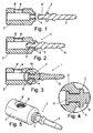
- a connector (1) being known in the corresponding art is illustrated in them, this type of connectors comprising a tubular body (2) one of whose ends forms an open end (4), and a connecting element (5) being formed by an elongated piece as a by way of stud having an intermediary annular stop collar (7).
- this connecting element (5) is previously arranged (see Fig. 1 ) in an aligned arrangement with respect to the tubular body (2), with its threaded back end (5') facing the also threaded open end (4) of the body (2), to thereupon and in a second stage ( Fig. 2 ) have it threadingly engaged into said open end till the stop collar (7) comes into abutment with it.
- the end (5') of the connecting element (5) is sufficiently long as from the stop collar (7) as to once having been fitted to the body (2) project in its inside from the back portion of the open end (4) so as to in a third and last stage ( Fig. 3 ) be riveted against this latter, the body (2) and the element (5) thus being perfectly and solidly connected together.
- the tubular body (2) conventionally has in its cylindrical surface a threaded hole (8) with a countersunk outer opening for the fitting of a screw (not shown) preferentially being of the dynamometric screw type and having a predetermined torque for its rupture when being tightened, for the fastening of the electrical lead of the cable to the electric connector, all this in order to prevent any tampering after the fitting operation, said screw being operable for gripping against the inner portion of the body (2) the pertinent electrical lead of the cable (neither shown) being introduced into said body through the free open end being opposite to the open end (4).
- the invention provides if necessary for the use of an intermediary piece between the elongated connecting element (5) and the tubular body (2), said intermediary piece being subjected to a riveting operation and being thus deformed and thus connecting together the contact surfaces of both pieces or elements namely being the elongated one (5) and the tubular one (2).
Landscapes
- Connections Effected By Soldering, Adhesion, Or Permanent Deformation (AREA)
Claims (3)
- Verfahren zum gegenseitigen Verbinden von Kontaktflächen für elektrische Anschlüsse bei der Ausbildung von elektrischen Verbindern, die aus zwei unterschiedlichen Teilen bestehen, was hauptsächlich die Art des Materials, die Form, die Abmessungen und andere Aspekte betrifft, wobei eines der Teile (2) röhrenförmig ist und die Verbindung der elektrischen Ader des entsprechenden Kabels bewirkt und das andere Teil (5) länglich ist und den Kontakt zur Herstellung der Verbindung von Ausrüstungsgegenständen, wie Transformatoren, elektrische Schalttafeln und dergleichen, bewirkt, dadurch gekennzeichnet, dass es folgende Schritte umfasst:- Ausrichten beider Teile in einer Weise, sodass das röhrenförmige Teil und das längliche Teil koaxial angeordnet sind;- Einführen eines Teilbereichs des länglichen Teils durch ein Ende des röhrenförmigen Teils bis zu einem dazwischenliegenden Anschlagbund (7), der am länglichen Teil vorgesehen ist; und- Vernieten des Teilbereichs des sich im Inneren des röhrenförmigen Teils befindlichen länglichen Teils an der Aussparung, die an das Einführungsende des röhrenförmigen Teils angrenzt; undbeide Teile sind an den gegenseitigen Kontaktflächen mit einem Gewinde versehen, wobei das längliche Teil durch ein Ende des röhrenförmigen Teils eingeführt und mit diesem durch Schraubbewegungen verbunden wird.
- Verfahren nach Anspruch 1, dadurch gekennzeichnet, dass die jeweiligen Flächen des länglichen Teils und das Einführungsende des röhrenförmigen Teils glatt sind und das Einpassen und Einführen des länglichen Teils in das Innere des röhrenförmigen Teils durch das besagte Ende dadurch erfolgt, dass es passgenau in dieses hineingeschoben wird.
- Verfahren nach Anspruch 1 oder 2, dadurch gekennzeichnet, dass zwischen den Teilbereich des im Inneren des röhrenförmigen Teils befindlichen länglichen Teils und die an das Einführungsende angrenzende Aussparung des röhrenförmigen Teils ein Zwischenstück eingefügt und die Vernietung dieses Zwischenstücks zwischen den beiden Teilen bewirkt wird.
Applications Claiming Priority (1)
| Application Number | Priority Date | Filing Date | Title |
|---|---|---|---|
| ES200700768A ES2339310B1 (es) | 2007-03-23 | 2007-03-23 | Metodo para la union de superficies de contacto para conexiones electricas. |
Publications (3)
| Publication Number | Publication Date |
|---|---|
| EP1973199A2 EP1973199A2 (de) | 2008-09-24 |
| EP1973199A3 EP1973199A3 (de) | 2011-08-10 |
| EP1973199B1 true EP1973199B1 (de) | 2013-07-17 |
Family
ID=39561872
Family Applications (1)
| Application Number | Title | Priority Date | Filing Date |
|---|---|---|---|
| EP08380096.1A Active EP1973199B1 (de) | 2007-03-23 | 2008-03-18 | Verfahren zum Verbinden von Kontaktflächen für elektrische Verbindungen |
Country Status (2)
| Country | Link |
|---|---|
| EP (1) | EP1973199B1 (de) |
| ES (2) | ES2339310B1 (de) |
Family Cites Families (7)
| Publication number | Priority date | Publication date | Assignee | Title |
|---|---|---|---|---|
| GB449395A (en) * | 1934-11-20 | 1936-06-22 | Ernst Kleinman | Improvements in electrical contact members |
| BE756564A (fr) * | 1970-09-24 | 1971-03-24 | Acec | Procede de fixation d'une broche de connexion electrique. |
| GB1527417A (en) * | 1976-07-29 | 1978-10-04 | Chi Man Fok | Electrical plugs |
| FR2687195B1 (fr) * | 1992-02-12 | 1995-07-07 | Eurocopter France | Organe d'assemblage a tete fraisee, tel qu'un rivet, pour l'assemblage de pieces en materiau composite munies de revetements electriquement conducteurs, et structure obtenue par cet assemblage. |
| US5476350A (en) * | 1993-10-28 | 1995-12-19 | Avdel Corporation - Systems Division | Slotted push-in rivet and method of riveting |
| DE19737098C1 (de) * | 1997-08-26 | 1999-05-06 | In Akustik Gmbh & Co Kg | Kontaktstecker |
| EP1659664A1 (de) * | 2004-11-18 | 2006-05-24 | Menber's S.p.A. | Verbinderanordnung zur elektrischen Verbindung zwischen Zugfahrzeug und Anhänger |
-
2007
- 2007-03-23 ES ES200700768A patent/ES2339310B1/es active Active
-
2008
- 2008-03-18 ES ES08380096T patent/ES2431147T3/es active Active
- 2008-03-18 EP EP08380096.1A patent/EP1973199B1/de active Active
Also Published As
| Publication number | Publication date |
|---|---|
| EP1973199A2 (de) | 2008-09-24 |
| ES2339310B1 (es) | 2011-05-06 |
| ES2431147T3 (es) | 2013-11-25 |
| ES2339310A1 (es) | 2010-05-18 |
| EP1973199A3 (de) | 2011-08-10 |
Similar Documents
| Publication | Publication Date | Title |
|---|---|---|
| US7938693B2 (en) | PE connection for plug connectors | |
| CA2946992C (en) | Hole-filling sleeve and washer design for bolt installation | |
| CA2914943C (en) | Coupling device | |
| US10128615B2 (en) | Variable-clocking terminal assembly | |
| US8317536B2 (en) | Ground clamp with ball contact stud | |
| MX2015005008A (es) | Aparato de union capaz de usarse en ambientes de interruptores de circuito y estructurado para conectar una terminal de anillo al interruptor de circuito. | |
| KR20100007644U (ko) | 케이블 접속장치 및 케이블 접속장치 조립체 | |
| US9543669B2 (en) | Supported termination | |
| CA2973448C (en) | Wire compression connector | |
| US20150072572A1 (en) | Locking Electrical Connector | |
| EP1973199A2 (de) | Verfahren zum Verbinden von Kontaktflächen für elektrische Verbindungen | |
| TW201427190A (zh) | 電連接器 | |
| US10431919B2 (en) | Connector for electrical power cables | |
| US3119472A (en) | Cable tray connector | |
| CN104134877A (zh) | 接线端钮与分流器/连接片一体化连接结构及其制备方法 | |
| US9531107B1 (en) | Tamper resistant power tap | |
| EP3108542A1 (de) | Verbesserter elektrischer steckverbinder | |
| US20070046417A1 (en) | Electrical connector housing and method of producing same | |
| US6910915B2 (en) | Terminal connector | |
| US12347966B2 (en) | Deadbreak connector | |
| JP5458192B1 (ja) | カバークランプ用連結金具 | |
| JP2020190270A (ja) | 長尺物接続具 | |
| KR20190094790A (ko) | 커넥터 | |
| US20070054567A1 (en) | Assembled connecting device | |
| US10741938B2 (en) | Terminal board for fastening electrical lines, and method for fastening electrical lines to a terminal board |
Legal Events
| Date | Code | Title | Description |
|---|---|---|---|
| PUAI | Public reference made under article 153(3) epc to a published international application that has entered the european phase |
Free format text: ORIGINAL CODE: 0009012 |
|
| AK | Designated contracting states |
Kind code of ref document: A2 Designated state(s): AT BE BG CH CY CZ DE DK EE ES FI FR GB GR HR HU IE IS IT LI LT LU LV MC MT NL NO PL PT RO SE SI SK TR |
|
| AX | Request for extension of the european patent |
Extension state: AL BA MK RS |
|
| RIN1 | Information on inventor provided before grant (corrected) |
Inventor name: CAPELLES DE LA FUENTE, ROSA |
|
| PUAL | Search report despatched |
Free format text: ORIGINAL CODE: 0009013 |
|
| AK | Designated contracting states |
Kind code of ref document: A3 Designated state(s): AT BE BG CH CY CZ DE DK EE ES FI FR GB GR HR HU IE IS IT LI LT LU LV MC MT NL NO PL PT RO SE SI SK TR |
|
| AX | Request for extension of the european patent |
Extension state: AL BA MK RS |
|
| RIC1 | Information provided on ipc code assigned before grant |
Ipc: H01R 101/00 20060101ALI20110707BHEP Ipc: H01R 4/06 20060101ALI20110707BHEP Ipc: H01R 11/18 20060101ALI20110707BHEP Ipc: H01R 4/62 20060101AFI20110707BHEP |
|
| 17P | Request for examination filed |
Effective date: 20110921 |
|
| AKX | Designation fees paid |
Designated state(s): AT BE BG CH CY CZ DE DK EE ES FI FR GB GR HR HU IE IS IT LI LT LU LV MC MT NL NO PL PT RO SE SI SK TR |
|
| GRAP | Despatch of communication of intention to grant a patent |
Free format text: ORIGINAL CODE: EPIDOSNIGR1 |
|
| RAP1 | Party data changed (applicant data changed or rights of an application transferred) |
Owner name: RIDELIN, S.L. |
|
| INTG | Intention to grant announced |
Effective date: 20130429 |
|
| GRAS | Grant fee paid |
Free format text: ORIGINAL CODE: EPIDOSNIGR3 |
|
| GRAA | (expected) grant |
Free format text: ORIGINAL CODE: 0009210 |
|
| AK | Designated contracting states |
Kind code of ref document: B1 Designated state(s): AT BE BG CH CY CZ DE DK EE ES FI FR GB GR HR HU IE IS IT LI LT LU LV MC MT NL NO PL PT RO SE SI SK TR |
|
| REG | Reference to a national code |
Ref country code: GB Ref legal event code: FG4D |
|
| REG | Reference to a national code |
Ref country code: CH Ref legal event code: EP |
|
| REG | Reference to a national code |
Ref country code: IE Ref legal event code: FG4D |
|
| REG | Reference to a national code |
Ref country code: AT Ref legal event code: REF Ref document number: 622702 Country of ref document: AT Kind code of ref document: T Effective date: 20130815 |
|
| REG | Reference to a national code |
Ref country code: DE Ref legal event code: R096 Ref document number: 602008026039 Country of ref document: DE Effective date: 20130912 |
|
| REG | Reference to a national code |
Ref country code: ES Ref legal event code: FG2A Ref document number: 2431147 Country of ref document: ES Kind code of ref document: T3 Effective date: 20131125 |
|
| REG | Reference to a national code |
Ref country code: AT Ref legal event code: MK05 Ref document number: 622702 Country of ref document: AT Kind code of ref document: T Effective date: 20130717 |
|
| REG | Reference to a national code |
Ref country code: NL Ref legal event code: VDEP Effective date: 20130717 |
|
| REG | Reference to a national code |
Ref country code: LT Ref legal event code: MG4D |
|
| PG25 | Lapsed in a contracting state [announced via postgrant information from national office to epo] |
Ref country code: BE Free format text: LAPSE BECAUSE OF FAILURE TO SUBMIT A TRANSLATION OF THE DESCRIPTION OR TO PAY THE FEE WITHIN THE PRESCRIBED TIME-LIMIT Effective date: 20130717 Ref country code: AT Free format text: LAPSE BECAUSE OF FAILURE TO SUBMIT A TRANSLATION OF THE DESCRIPTION OR TO PAY THE FEE WITHIN THE PRESCRIBED TIME-LIMIT Effective date: 20130717 Ref country code: CY Free format text: LAPSE BECAUSE OF FAILURE TO SUBMIT A TRANSLATION OF THE DESCRIPTION OR TO PAY THE FEE WITHIN THE PRESCRIBED TIME-LIMIT Effective date: 20130626 Ref country code: PT Free format text: LAPSE BECAUSE OF FAILURE TO SUBMIT A TRANSLATION OF THE DESCRIPTION OR TO PAY THE FEE WITHIN THE PRESCRIBED TIME-LIMIT Effective date: 20131118 Ref country code: SE Free format text: LAPSE BECAUSE OF FAILURE TO SUBMIT A TRANSLATION OF THE DESCRIPTION OR TO PAY THE FEE WITHIN THE PRESCRIBED TIME-LIMIT Effective date: 20130717 Ref country code: LT Free format text: LAPSE BECAUSE OF FAILURE TO SUBMIT A TRANSLATION OF THE DESCRIPTION OR TO PAY THE FEE WITHIN THE PRESCRIBED TIME-LIMIT Effective date: 20130717 Ref country code: IS Free format text: LAPSE BECAUSE OF FAILURE TO SUBMIT A TRANSLATION OF THE DESCRIPTION OR TO PAY THE FEE WITHIN THE PRESCRIBED TIME-LIMIT Effective date: 20131117 Ref country code: NO Free format text: LAPSE BECAUSE OF FAILURE TO SUBMIT A TRANSLATION OF THE DESCRIPTION OR TO PAY THE FEE WITHIN THE PRESCRIBED TIME-LIMIT Effective date: 20131017 Ref country code: HR Free format text: LAPSE BECAUSE OF FAILURE TO SUBMIT A TRANSLATION OF THE DESCRIPTION OR TO PAY THE FEE WITHIN THE PRESCRIBED TIME-LIMIT Effective date: 20130717 |
|
| PG25 | Lapsed in a contracting state [announced via postgrant information from national office to epo] |
Ref country code: LV Free format text: LAPSE BECAUSE OF FAILURE TO SUBMIT A TRANSLATION OF THE DESCRIPTION OR TO PAY THE FEE WITHIN THE PRESCRIBED TIME-LIMIT Effective date: 20130717 Ref country code: GR Free format text: LAPSE BECAUSE OF FAILURE TO SUBMIT A TRANSLATION OF THE DESCRIPTION OR TO PAY THE FEE WITHIN THE PRESCRIBED TIME-LIMIT Effective date: 20131018 Ref country code: SI Free format text: LAPSE BECAUSE OF FAILURE TO SUBMIT A TRANSLATION OF THE DESCRIPTION OR TO PAY THE FEE WITHIN THE PRESCRIBED TIME-LIMIT Effective date: 20130717 Ref country code: NL Free format text: LAPSE BECAUSE OF FAILURE TO SUBMIT A TRANSLATION OF THE DESCRIPTION OR TO PAY THE FEE WITHIN THE PRESCRIBED TIME-LIMIT Effective date: 20130717 Ref country code: PL Free format text: LAPSE BECAUSE OF FAILURE TO SUBMIT A TRANSLATION OF THE DESCRIPTION OR TO PAY THE FEE WITHIN THE PRESCRIBED TIME-LIMIT Effective date: 20130717 Ref country code: FI Free format text: LAPSE BECAUSE OF FAILURE TO SUBMIT A TRANSLATION OF THE DESCRIPTION OR TO PAY THE FEE WITHIN THE PRESCRIBED TIME-LIMIT Effective date: 20130717 |
|
| PG25 | Lapsed in a contracting state [announced via postgrant information from national office to epo] |
Ref country code: CY Free format text: LAPSE BECAUSE OF FAILURE TO SUBMIT A TRANSLATION OF THE DESCRIPTION OR TO PAY THE FEE WITHIN THE PRESCRIBED TIME-LIMIT Effective date: 20130717 |
|
| PG25 | Lapsed in a contracting state [announced via postgrant information from national office to epo] |
Ref country code: CZ Free format text: LAPSE BECAUSE OF FAILURE TO SUBMIT A TRANSLATION OF THE DESCRIPTION OR TO PAY THE FEE WITHIN THE PRESCRIBED TIME-LIMIT Effective date: 20130717 Ref country code: EE Free format text: LAPSE BECAUSE OF FAILURE TO SUBMIT A TRANSLATION OF THE DESCRIPTION OR TO PAY THE FEE WITHIN THE PRESCRIBED TIME-LIMIT Effective date: 20130717 Ref country code: SK Free format text: LAPSE BECAUSE OF FAILURE TO SUBMIT A TRANSLATION OF THE DESCRIPTION OR TO PAY THE FEE WITHIN THE PRESCRIBED TIME-LIMIT Effective date: 20130717 Ref country code: DK Free format text: LAPSE BECAUSE OF FAILURE TO SUBMIT A TRANSLATION OF THE DESCRIPTION OR TO PAY THE FEE WITHIN THE PRESCRIBED TIME-LIMIT Effective date: 20130717 Ref country code: RO Free format text: LAPSE BECAUSE OF FAILURE TO SUBMIT A TRANSLATION OF THE DESCRIPTION OR TO PAY THE FEE WITHIN THE PRESCRIBED TIME-LIMIT Effective date: 20130717 |
|
| PLBE | No opposition filed within time limit |
Free format text: ORIGINAL CODE: 0009261 |
|
| STAA | Information on the status of an ep patent application or granted ep patent |
Free format text: STATUS: NO OPPOSITION FILED WITHIN TIME LIMIT |
|
| 26N | No opposition filed |
Effective date: 20140422 |
|
| REG | Reference to a national code |
Ref country code: DE Ref legal event code: R097 Ref document number: 602008026039 Country of ref document: DE Effective date: 20140422 |
|
| PG25 | Lapsed in a contracting state [announced via postgrant information from national office to epo] |
Ref country code: LU Free format text: LAPSE BECAUSE OF FAILURE TO SUBMIT A TRANSLATION OF THE DESCRIPTION OR TO PAY THE FEE WITHIN THE PRESCRIBED TIME-LIMIT Effective date: 20140318 |
|
| REG | Reference to a national code |
Ref country code: CH Ref legal event code: PL |
|
| GBPC | Gb: european patent ceased through non-payment of renewal fee |
Effective date: 20140318 |
|
| REG | Reference to a national code |
Ref country code: IE Ref legal event code: MM4A |
|
| PG25 | Lapsed in a contracting state [announced via postgrant information from national office to epo] |
Ref country code: GB Free format text: LAPSE BECAUSE OF NON-PAYMENT OF DUE FEES Effective date: 20140318 Ref country code: LI Free format text: LAPSE BECAUSE OF NON-PAYMENT OF DUE FEES Effective date: 20140331 Ref country code: IE Free format text: LAPSE BECAUSE OF NON-PAYMENT OF DUE FEES Effective date: 20140318 Ref country code: CH Free format text: LAPSE BECAUSE OF NON-PAYMENT OF DUE FEES Effective date: 20140331 |
|
| PG25 | Lapsed in a contracting state [announced via postgrant information from national office to epo] |
Ref country code: MT Free format text: LAPSE BECAUSE OF FAILURE TO SUBMIT A TRANSLATION OF THE DESCRIPTION OR TO PAY THE FEE WITHIN THE PRESCRIBED TIME-LIMIT Effective date: 20130717 |
|
| REG | Reference to a national code |
Ref country code: FR Ref legal event code: PLFP Year of fee payment: 9 |
|
| PG25 | Lapsed in a contracting state [announced via postgrant information from national office to epo] |
Ref country code: MC Free format text: LAPSE BECAUSE OF FAILURE TO SUBMIT A TRANSLATION OF THE DESCRIPTION OR TO PAY THE FEE WITHIN THE PRESCRIBED TIME-LIMIT Effective date: 20130717 Ref country code: BG Free format text: LAPSE BECAUSE OF FAILURE TO SUBMIT A TRANSLATION OF THE DESCRIPTION OR TO PAY THE FEE WITHIN THE PRESCRIBED TIME-LIMIT Effective date: 20130717 |
|
| PG25 | Lapsed in a contracting state [announced via postgrant information from national office to epo] |
Ref country code: HU Free format text: LAPSE BECAUSE OF FAILURE TO SUBMIT A TRANSLATION OF THE DESCRIPTION OR TO PAY THE FEE WITHIN THE PRESCRIBED TIME-LIMIT; INVALID AB INITIO Effective date: 20080318 Ref country code: TR Free format text: LAPSE BECAUSE OF FAILURE TO SUBMIT A TRANSLATION OF THE DESCRIPTION OR TO PAY THE FEE WITHIN THE PRESCRIBED TIME-LIMIT Effective date: 20130717 |
|
| REG | Reference to a national code |
Ref country code: FR Ref legal event code: PLFP Year of fee payment: 10 |
|
| REG | Reference to a national code |
Ref country code: FR Ref legal event code: PLFP Year of fee payment: 11 |
|
| PGFP | Annual fee paid to national office [announced via postgrant information from national office to epo] |
Ref country code: FR Payment date: 20230110 Year of fee payment: 16 |
|
| PGFP | Annual fee paid to national office [announced via postgrant information from national office to epo] |
Ref country code: IT Payment date: 20230213 Year of fee payment: 16 Ref country code: DE Payment date: 20230125 Year of fee payment: 16 |
|
| REG | Reference to a national code |
Ref country code: DE Ref legal event code: R082 Ref document number: 602008026039 Country of ref document: DE Representative=s name: KANDLBINDER, MARKUS, DIPL.-PHYS., DE |
|
| REG | Reference to a national code |
Ref country code: DE Ref legal event code: R119 Ref document number: 602008026039 Country of ref document: DE |
|
| PG25 | Lapsed in a contracting state [announced via postgrant information from national office to epo] |
Ref country code: DE Free format text: LAPSE BECAUSE OF NON-PAYMENT OF DUE FEES Effective date: 20241001 |
|
| PG25 | Lapsed in a contracting state [announced via postgrant information from national office to epo] |
Ref country code: FR Free format text: LAPSE BECAUSE OF NON-PAYMENT OF DUE FEES Effective date: 20240331 |
|
| PG25 | Lapsed in a contracting state [announced via postgrant information from national office to epo] |
Ref country code: FR Free format text: LAPSE BECAUSE OF NON-PAYMENT OF DUE FEES Effective date: 20240331 Ref country code: DE Free format text: LAPSE BECAUSE OF NON-PAYMENT OF DUE FEES Effective date: 20241001 |
|
| PG25 | Lapsed in a contracting state [announced via postgrant information from national office to epo] |
Ref country code: IT Free format text: LAPSE BECAUSE OF NON-PAYMENT OF DUE FEES Effective date: 20240318 |
|
| PGFP | Annual fee paid to national office [announced via postgrant information from national office to epo] |
Ref country code: ES Payment date: 20250401 Year of fee payment: 18 |