US8317536B2 - Ground clamp with ball contact stud - Google Patents
Ground clamp with ball contact stud Download PDFInfo
- Publication number
- US8317536B2 US8317536B2 US12/884,613 US88461310A US8317536B2 US 8317536 B2 US8317536 B2 US 8317536B2 US 88461310 A US88461310 A US 88461310A US 8317536 B2 US8317536 B2 US 8317536B2
- Authority
- US
- United States
- Prior art keywords
- clamp
- assembly
- ball stud
- perforation
- socket
- Prior art date
- Legal status (The legal status is an assumption and is not a legal conclusion. Google has not performed a legal analysis and makes no representation as to the accuracy of the status listed.)
- Active, expires
Links
Images


Classifications
-
- H—ELECTRICITY
- H01—ELECTRIC ELEMENTS
- H01R—ELECTRICALLY-CONDUCTIVE CONNECTIONS; STRUCTURAL ASSOCIATIONS OF A PLURALITY OF MUTUALLY-INSULATED ELECTRICAL CONNECTING ELEMENTS; COUPLING DEVICES; CURRENT COLLECTORS
- H01R4/00—Electrically-conductive connections between two or more conductive members in direct contact, i.e. touching one another; Means for effecting or maintaining such contact; Electrically-conductive connections having two or more spaced connecting locations for conductors and using contact members penetrating insulation
- H01R4/28—Clamped connections, spring connections
- H01R4/30—Clamped connections, spring connections utilising a screw or nut clamping member
-
- H—ELECTRICITY
- H01—ELECTRIC ELEMENTS
- H01R—ELECTRICALLY-CONDUCTIVE CONNECTIONS; STRUCTURAL ASSOCIATIONS OF A PLURALITY OF MUTUALLY-INSULATED ELECTRICAL CONNECTING ELEMENTS; COUPLING DEVICES; CURRENT COLLECTORS
- H01R4/00—Electrically-conductive connections between two or more conductive members in direct contact, i.e. touching one another; Means for effecting or maintaining such contact; Electrically-conductive connections having two or more spaced connecting locations for conductors and using contact members penetrating insulation
- H01R4/58—Electrically-conductive connections between two or more conductive members in direct contact, i.e. touching one another; Means for effecting or maintaining such contact; Electrically-conductive connections having two or more spaced connecting locations for conductors and using contact members penetrating insulation characterised by the form or material of the contacting members
- H01R4/64—Connections between or with conductive parts having primarily a non-electric function, e.g. frame, casing, rail
-
- Y—GENERAL TAGGING OF NEW TECHNOLOGICAL DEVELOPMENTS; GENERAL TAGGING OF CROSS-SECTIONAL TECHNOLOGIES SPANNING OVER SEVERAL SECTIONS OF THE IPC; TECHNICAL SUBJECTS COVERED BY FORMER USPC CROSS-REFERENCE ART COLLECTIONS [XRACs] AND DIGESTS
- Y10—TECHNICAL SUBJECTS COVERED BY FORMER USPC
- Y10T—TECHNICAL SUBJECTS COVERED BY FORMER US CLASSIFICATION
- Y10T403/00—Joints and connections
- Y10T403/32—Articulated members
- Y10T403/32606—Pivoted
- Y10T403/32861—T-pivot, e.g., wrist pin, etc.
- Y10T403/32893—T-pivot, e.g., wrist pin, etc. including distinct pin retainer
Definitions
- the invention pertains to ground clamps. More particularly, the invention pertains to such clamps as are used in the electrical utility industry as protective-grounding equipment.
- C-type clamps are a known form of grounding clamp used for this purpose.
- One commercially available C-type clamp is available as a Salisbury 21074 2′′ grounding clamp.
- Known C-type clamps often have provisions for the installation of metal ball studs.
- a Salisbury No. 21192 externally threaded ball stud can be passed through a hole in a C-type clamp and threaded onto a Salisbury 24082 internally threaded ball stud.
- ball studs to clamps often use a round hole, which might be treaded, in the clamp.
- the ball studs can be permanently attached by welding to the respective clamp.
- FIG. 1A is a perspective view of a C-type clamp in accordance with the invention.
- FIG. 1B is a view of a first side of the clamp of FIG. 1A with an attached, internally threaded ball stud;
- FIG. 1C is a view of a second side of the clamp of FIG. 1A with an attached externally threaded ball stud;
- FIG. 1D is an end view of the clamp of FIG. 1A ;
- FIG. 2A is a front view of the C-type clamp of FIG. 1A ;
- FIG. 2B is a side view of the clamp of FIG. 2A ;
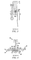
- FIG. 3 is a half-sized, sectional view, along plane 3 - 3 of FIG. 2A ;
- FIG. 4 is a half-sized, sectional view, along plane 4 - 4 of FIG. 2B .
- a clamp which embodies the invention has a metal ground clamp with a hexagonal pocket with a thru hole formed in the rear section of the body's flange.
- the pocket will receive the base section of an internal, female, metal ball stud.
- the opposite side will accept a male metal ball stud which can feed through the hold and thread into the internal ball stud.
- the clamp enables the female ball stud to seat into the body of the clamp, and be non-rotatable relative to the clamp, and the male ball stud to feed through from the opposite side of the clamp.
- the male ball stud provides a mechanism to tighten the studs to the clamp.
- a Salisbury internal ball stud such as No. 24082 can threadably engage a Salisbury ball stud No. 21191.
- the figures illustrate various aspects of embodiments of the invention. Section 4 - 4 illustrates the internal treaded engagement of the internal ball stud and the male ball stud. Section 3 - 3 illustrates the hexagonal shape of a portion of the body of the female ball stud.
- a C-type clamp 10 has first and second spaced apart body sections 12 a,b joined by center section 12 c.
- a through-hole 14 a extends through the section 12 c.
- a multi-sided, hexagonal for example, socket or pocket 14 b is formed in a region 12 d of the center section 12 c, best seen in FIG. 1B .
- the socket 14 b does not extend entirely through central section 12 a as does the through-hole 14 a .
- both the through-hole 14 a and the socket 14 b have a common central axis, A, best see in FIG. 4 .
- First and second ball studs, 20 , 24 are carried by clamp 10 .
- the ball studs 20 , 24 threadably engage one another.
- ball stud 20 has an exterior spherical end 20 a, a cylindrical stem 20 b and a multi-sided hexagonal collar 20 c which slidably engages the depression 14 b with the mating shape.
- the ball stud 20 carries internal threads 20 d.
- the ball stud 24 carries external threads 24 d which rotatably engage the internal threads 20 d trapping or, sandwiching, the clamp 10 therebetween.
- the ball stud 24 carries an external collar 24 c which slidably engages exterior surface 18 of the region 12 c as the two studs 20 , 24 are rotated toward one another.
- the frame portion 12 c blocks rotation of the stud 20 due to the interaction between depression 14 b and the exterior collar 20 c thereby providing a locked together assembly of the clamp 10 and studs 20 , 24 .
Landscapes
- Pivots And Pivotal Connections (AREA)
Abstract
Description
Claims (20)
Priority Applications (1)
| Application Number | Priority Date | Filing Date | Title |
|---|---|---|---|
| US12/884,613 US8317536B2 (en) | 2009-10-05 | 2010-09-17 | Ground clamp with ball contact stud |
Applications Claiming Priority (2)
| Application Number | Priority Date | Filing Date | Title |
|---|---|---|---|
| US24857909P | 2009-10-05 | 2009-10-05 | |
| US12/884,613 US8317536B2 (en) | 2009-10-05 | 2010-09-17 | Ground clamp with ball contact stud |
Publications (2)
| Publication Number | Publication Date |
|---|---|
| US20110081810A1 US20110081810A1 (en) | 2011-04-07 |
| US8317536B2 true US8317536B2 (en) | 2012-11-27 |
Family
ID=43823518
Family Applications (1)
| Application Number | Title | Priority Date | Filing Date |
|---|---|---|---|
| US12/884,613 Active 2031-03-19 US8317536B2 (en) | 2009-10-05 | 2010-09-17 | Ground clamp with ball contact stud |
Country Status (1)
| Country | Link |
|---|---|
| US (1) | US8317536B2 (en) |
Cited By (4)
| Publication number | Priority date | Publication date | Assignee | Title |
|---|---|---|---|---|
| US8517776B1 (en) * | 2012-03-06 | 2013-08-27 | Honeywell International Inc. | Ground clamp for use with ball stud ground conductors |
| US10230181B2 (en) | 2017-06-12 | 2019-03-12 | Hubbell Incorporated | All-angle ground clamps |
| US10673152B2 (en) | 2016-05-02 | 2020-06-02 | Quanta Associates, L.P. | Locking grounding clamp |
| US11817665B2 (en) | 2021-01-29 | 2023-11-14 | Quanta Associates, L.P. | Spring loaded ground clamp |
Families Citing this family (4)
| Publication number | Priority date | Publication date | Assignee | Title |
|---|---|---|---|---|
| US8317536B2 (en) * | 2009-10-05 | 2012-11-27 | Honeywell International Inc. | Ground clamp with ball contact stud |
| WO2018044745A1 (en) * | 2016-08-30 | 2018-03-08 | Honeywell International Inc. | Cam driven, spring loaded grounding clamp |
| CA3003977A1 (en) * | 2017-05-05 | 2018-11-05 | Huys Industries Limited | Welding ground apparatus |
| USD953157S1 (en) * | 2020-07-17 | 2022-05-31 | Honeywell International Inc. | Clamp |
Citations (6)
| Publication number | Priority date | Publication date | Assignee | Title |
|---|---|---|---|---|
| US5556299A (en) * | 1995-03-23 | 1996-09-17 | Houston Industries Incorporated | Self-latching clamp for power lines |
| US20040182593A1 (en) * | 2003-03-21 | 2004-09-23 | Larry Sumner | Electrical conductor interconnection apparatus |
| US7160142B2 (en) * | 2005-01-04 | 2007-01-09 | Cooper Technologies Company | Grounding clamp apparatus and method |
| US20080026613A1 (en) * | 2006-07-26 | 2008-01-31 | De France Robert V | Conductor Connection |
| US20090103974A1 (en) * | 2007-10-18 | 2009-04-23 | Honda Motor Co., Ltd. | Ball stud system for use within a ball joint |
| US20110081810A1 (en) * | 2009-10-05 | 2011-04-07 | Honeywell International Inc. | Ground Clamp with Ball Contact Stud |
-
2010
- 2010-09-17 US US12/884,613 patent/US8317536B2/en active Active
Patent Citations (10)
| Publication number | Priority date | Publication date | Assignee | Title |
|---|---|---|---|---|
| US5556299A (en) * | 1995-03-23 | 1996-09-17 | Houston Industries Incorporated | Self-latching clamp for power lines |
| US20040182593A1 (en) * | 2003-03-21 | 2004-09-23 | Larry Sumner | Electrical conductor interconnection apparatus |
| US6891106B2 (en) * | 2003-03-21 | 2005-05-10 | Enmax Corporation | Electrical conductor interconnection apparatus |
| US7160142B2 (en) * | 2005-01-04 | 2007-01-09 | Cooper Technologies Company | Grounding clamp apparatus and method |
| US20080026613A1 (en) * | 2006-07-26 | 2008-01-31 | De France Robert V | Conductor Connection |
| US7485014B2 (en) * | 2006-07-26 | 2009-02-03 | Fci Americas Technology, Inc. | Conductor connection |
| US20090130872A1 (en) * | 2006-07-26 | 2009-05-21 | De France Robert V | Conductor connection |
| US7614923B2 (en) * | 2006-07-26 | 2009-11-10 | Fci Americas Technology, Inc. | Conductor connection |
| US20090103974A1 (en) * | 2007-10-18 | 2009-04-23 | Honda Motor Co., Ltd. | Ball stud system for use within a ball joint |
| US20110081810A1 (en) * | 2009-10-05 | 2011-04-07 | Honeywell International Inc. | Ground Clamp with Ball Contact Stud |
Non-Patent Citations (1)
| Title |
|---|
| Hubbell Power Systems, Inc.; Personal Protective Equipment; Catalog; Copyright 2008; pp. 8-1 to 8-11; Section 8; Hubbell Incorporated; www.hubbellpowersystems.com; hpsliterature@hps.hubbell.com. |
Cited By (4)
| Publication number | Priority date | Publication date | Assignee | Title |
|---|---|---|---|---|
| US8517776B1 (en) * | 2012-03-06 | 2013-08-27 | Honeywell International Inc. | Ground clamp for use with ball stud ground conductors |
| US10673152B2 (en) | 2016-05-02 | 2020-06-02 | Quanta Associates, L.P. | Locking grounding clamp |
| US10230181B2 (en) | 2017-06-12 | 2019-03-12 | Hubbell Incorporated | All-angle ground clamps |
| US11817665B2 (en) | 2021-01-29 | 2023-11-14 | Quanta Associates, L.P. | Spring loaded ground clamp |
Also Published As
| Publication number | Publication date |
|---|---|
| US20110081810A1 (en) | 2011-04-07 |
Similar Documents
| Publication | Publication Date | Title |
|---|---|---|
| US8317536B2 (en) | Ground clamp with ball contact stud | |
| US8864504B1 (en) | Intersystem grounding clamp with serrated gripping surfaces and a plurality of grounding terminals | |
| US8047868B1 (en) | Stud-type junction block | |
| US10230181B2 (en) | All-angle ground clamps | |
| CN111009747B (en) | Amp wire clamp | |
| US8517776B1 (en) | Ground clamp for use with ball stud ground conductors | |
| MX2009007716A (en) | Locking pin. | |
| AU2017305418A1 (en) | Tap clamp | |
| JP4881954B2 (en) | Battery cable connector device | |
| DE102018208029B4 (en) | Connection device | |
| US10637164B2 (en) | Bonding connectors | |
| US10454191B2 (en) | Connectors for electrical jumper cables | |
| JP5312432B2 (en) | Power cable connection device and method for assembling the same | |
| KR101723951B1 (en) | Elbow with internal assembly system | |
| CN204012078U (en) | The multi-functional grounding wire device of using | |
| US6891106B2 (en) | Electrical conductor interconnection apparatus | |
| JP2005203178A (en) | Battery terminal connection structure | |
| US20150072572A1 (en) | Locking Electrical Connector | |
| EP3058620A1 (en) | Battery terminal | |
| US9021923B2 (en) | Torque wrench adaptor tool assembly and methods of operating the same | |
| CN103629223B (en) | Power connection structure | |
| US3369215A (en) | Battery terminal clamp for emergency and/or permanent cable connection | |
| US10236621B2 (en) | Electrical connector with conduit adapter | |
| CN203644959U (en) | Wiring Sets and Wiring Plugs | |
| CN103236598A (en) | Terminal Connection Structure of Stainless Steel Composite Ground Lead |
Legal Events
| Date | Code | Title | Description |
|---|---|---|---|
| AS | Assignment |
Owner name: HONEYWELL INTERNATIONAL INC., NEW JERSEY Free format text: ASSIGNMENT OF ASSIGNORS INTEREST;ASSIGNOR:FLOJO, ALFRED R., MR.;REEL/FRAME:025211/0519 Effective date: 20101019 |
|
| STCF | Information on status: patent grant |
Free format text: PATENTED CASE |
|
| FPAY | Fee payment |
Year of fee payment: 4 |
|
| MAFP | Maintenance fee payment |
Free format text: PAYMENT OF MAINTENANCE FEE, 8TH YEAR, LARGE ENTITY (ORIGINAL EVENT CODE: M1552); ENTITY STATUS OF PATENT OWNER: LARGE ENTITY Year of fee payment: 8 |
|
| MAFP | Maintenance fee payment |
Free format text: PAYMENT OF MAINTENANCE FEE, 12TH YEAR, LARGE ENTITY (ORIGINAL EVENT CODE: M1553); ENTITY STATUS OF PATENT OWNER: LARGE ENTITY Year of fee payment: 12 |
|
| AS | Assignment |
Owner name: HONEYWELL SAFETY PRODUCTS USA, INC., NORTH CAROLINA Free format text: ASSIGNMENT OF ASSIGNORS INTEREST;ASSIGNOR:HONEYWELL INTERNATIONAL INC.;REEL/FRAME:070538/0643 Effective date: 20250203 |
|
| AS | Assignment |
Owner name: GOLDMAN SACHS BANK USA, TEXAS Free format text: SECURITY INTEREST;ASSIGNORS:PROTECTIVE INDUSTRIAL PRODUCTS, INC.;WORLDWIDE PROTECTIVE PRODUCTS, LLC;HEAROS, LLC;AND OTHERS;REEL/FRAME:071342/0241 Effective date: 20250522 Owner name: JPMORGAN CHASE BANK, N.A., ILLINOIS Free format text: SECURITY INTEREST;ASSIGNORS:PROTECTIVE INDUSTRIAL PRODUCTS, INC.;WORLDWIDE PROTECTIVE PRODUCTS, LLC;HEAROS, LLC;AND OTHERS;REEL/FRAME:071346/0679 Effective date: 20250522 |