EP1972914A2 - Verfahren zur Verhinderung eines Übertemperaturzustands in einem Gasturbinenmotor - Google Patents
Verfahren zur Verhinderung eines Übertemperaturzustands in einem Gasturbinenmotor Download PDFInfo
- Publication number
- EP1972914A2 EP1972914A2 EP07123238A EP07123238A EP1972914A2 EP 1972914 A2 EP1972914 A2 EP 1972914A2 EP 07123238 A EP07123238 A EP 07123238A EP 07123238 A EP07123238 A EP 07123238A EP 1972914 A2 EP1972914 A2 EP 1972914A2
- Authority
- EP
- European Patent Office
- Prior art keywords
- fuse
- condition
- signal tube
- engine
- signal
- Prior art date
- Legal status (The legal status is an assumption and is not a legal conclusion. Google has not performed a legal analysis and makes no representation as to the accuracy of the status listed.)
- Withdrawn
Links
- 238000000034 method Methods 0.000 title claims abstract description 17
- 239000012530 fluid Substances 0.000 claims abstract description 17
- 230000003068 static effect Effects 0.000 claims abstract description 7
- 230000037361 pathway Effects 0.000 claims description 19
- 239000007789 gas Substances 0.000 description 7
- 239000000463 material Substances 0.000 description 5
- 239000002184 metal Substances 0.000 description 5
- 239000002131 composite material Substances 0.000 description 2
- 239000000155 melt Substances 0.000 description 2
- 230000002787 reinforcement Effects 0.000 description 2
- 230000016776 visual perception Effects 0.000 description 2
- 238000005219 brazing Methods 0.000 description 1
- 150000001875 compounds Chemical class 0.000 description 1
- 238000001514 detection method Methods 0.000 description 1
- 238000002845 discoloration Methods 0.000 description 1
- 231100001261 hazardous Toxicity 0.000 description 1
- -1 i.e. Substances 0.000 description 1
- 238000009413 insulation Methods 0.000 description 1
- 238000012423 maintenance Methods 0.000 description 1
- 238000002844 melting Methods 0.000 description 1
- 230000008018 melting Effects 0.000 description 1
- 230000000007 visual effect Effects 0.000 description 1
- 238000011179 visual inspection Methods 0.000 description 1
Images


Classifications
-
- G—PHYSICS
- G01—MEASURING; TESTING
- G01K—MEASURING TEMPERATURE; MEASURING QUANTITY OF HEAT; THERMALLY-SENSITIVE ELEMENTS NOT OTHERWISE PROVIDED FOR
- G01K11/00—Measuring temperature based upon physical or chemical changes not covered by groups G01K3/00, G01K5/00, G01K7/00 or G01K9/00
- G01K11/06—Measuring temperature based upon physical or chemical changes not covered by groups G01K3/00, G01K5/00, G01K7/00 or G01K9/00 using melting, freezing, or softening
-
- F—MECHANICAL ENGINEERING; LIGHTING; HEATING; WEAPONS; BLASTING
- F01—MACHINES OR ENGINES IN GENERAL; ENGINE PLANTS IN GENERAL; STEAM ENGINES
- F01D—NON-POSITIVE DISPLACEMENT MACHINES OR ENGINES, e.g. STEAM TURBINES
- F01D17/00—Regulating or controlling by varying flow
- F01D17/02—Arrangement of sensing elements
- F01D17/08—Arrangement of sensing elements responsive to condition of working-fluid, e.g. pressure
-
- F—MECHANICAL ENGINEERING; LIGHTING; HEATING; WEAPONS; BLASTING
- F01—MACHINES OR ENGINES IN GENERAL; ENGINE PLANTS IN GENERAL; STEAM ENGINES
- F01D—NON-POSITIVE DISPLACEMENT MACHINES OR ENGINES, e.g. STEAM TURBINES
- F01D21/00—Shutting-down of machines or engines, e.g. in emergency; Regulating, controlling, or safety means not otherwise provided for
- F01D21/12—Shutting-down of machines or engines, e.g. in emergency; Regulating, controlling, or safety means not otherwise provided for responsive to temperature
-
- F—MECHANICAL ENGINEERING; LIGHTING; HEATING; WEAPONS; BLASTING
- F01—MACHINES OR ENGINES IN GENERAL; ENGINE PLANTS IN GENERAL; STEAM ENGINES
- F01D—NON-POSITIVE DISPLACEMENT MACHINES OR ENGINES, e.g. STEAM TURBINES
- F01D21/00—Shutting-down of machines or engines, e.g. in emergency; Regulating, controlling, or safety means not otherwise provided for
- F01D21/14—Shutting-down of machines or engines, e.g. in emergency; Regulating, controlling, or safety means not otherwise provided for responsive to other specific conditions
-
- F—MECHANICAL ENGINEERING; LIGHTING; HEATING; WEAPONS; BLASTING
- F02—COMBUSTION ENGINES; HOT-GAS OR COMBUSTION-PRODUCT ENGINE PLANTS
- F02C—GAS-TURBINE PLANTS; AIR INTAKES FOR JET-PROPULSION PLANTS; CONTROLLING FUEL SUPPLY IN AIR-BREATHING JET-PROPULSION PLANTS
- F02C7/00—Features, components parts, details or accessories, not provided for in, or of interest apart form groups F02C1/00 - F02C6/00; Air intakes for jet-propulsion plants
- F02C7/24—Heat or noise insulation
- F02C7/25—Fire protection or prevention
-
- F—MECHANICAL ENGINEERING; LIGHTING; HEATING; WEAPONS; BLASTING
- F05—INDEXING SCHEMES RELATING TO ENGINES OR PUMPS IN VARIOUS SUBCLASSES OF CLASSES F01-F04
- F05D—INDEXING SCHEME FOR ASPECTS RELATING TO NON-POSITIVE-DISPLACEMENT MACHINES OR ENGINES, GAS-TURBINES OR JET-PROPULSION PLANTS
- F05D2270/00—Control
- F05D2270/01—Purpose of the control system
- F05D2270/09—Purpose of the control system to cope with emergencies
-
- F—MECHANICAL ENGINEERING; LIGHTING; HEATING; WEAPONS; BLASTING
- F05—INDEXING SCHEMES RELATING TO ENGINES OR PUMPS IN VARIOUS SUBCLASSES OF CLASSES F01-F04
- F05D—INDEXING SCHEME FOR ASPECTS RELATING TO NON-POSITIVE-DISPLACEMENT MACHINES OR ENGINES, GAS-TURBINES OR JET-PROPULSION PLANTS
- F05D2270/00—Control
- F05D2270/30—Control parameters, e.g. input parameters
- F05D2270/301—Pressure
-
- F—MECHANICAL ENGINEERING; LIGHTING; HEATING; WEAPONS; BLASTING
- F05—INDEXING SCHEMES RELATING TO ENGINES OR PUMPS IN VARIOUS SUBCLASSES OF CLASSES F01-F04
- F05D—INDEXING SCHEME FOR ASPECTS RELATING TO NON-POSITIVE-DISPLACEMENT MACHINES OR ENGINES, GAS-TURBINES OR JET-PROPULSION PLANTS
- F05D2270/00—Control
- F05D2270/30—Control parameters, e.g. input parameters
- F05D2270/303—Temperature
-
- Y—GENERAL TAGGING OF NEW TECHNOLOGICAL DEVELOPMENTS; GENERAL TAGGING OF CROSS-SECTIONAL TECHNOLOGIES SPANNING OVER SEVERAL SECTIONS OF THE IPC; TECHNICAL SUBJECTS COVERED BY FORMER USPC CROSS-REFERENCE ART COLLECTIONS [XRACs] AND DIGESTS
- Y02—TECHNOLOGIES OR APPLICATIONS FOR MITIGATION OR ADAPTATION AGAINST CLIMATE CHANGE
- Y02T—CLIMATE CHANGE MITIGATION TECHNOLOGIES RELATED TO TRANSPORTATION
- Y02T50/00—Aeronautics or air transport
- Y02T50/60—Efficient propulsion technologies, e.g. for aircraft
Definitions
- This invention relates generally to systems and apparatuses for preventing over temperature conditions in a non-fire zone of an aircraft engine, and more specifically to an over temperature fuse in a signal tube.
- the full authority digital electronics control (FADEC) for a gas turbine engine utilizes a pressure signal from the combustor for control of the engine. Because a broken signal tube could allow hot air to enter the fan compartment, a non-fire zone, the FADEC shuts down the engine in a broken signal tube condition.
- the broken signal tube could be due to, for example, improper maintenance, tube fatigue, or foreign object damage from the aircraft to the engine.
- the signal tube is usually not insulated in the non-fire zone. Additionally, many engine programs use composites in the fan and nacelle compartments where leaking high temperature air can do damage. Temperature sensors and shut-off valves could be used to minimize the risk of leakage, but reliability, cost, and weight are negative factors.
- a method in an exemplary embodiment, includes providing a signal tube extending generally from an engine component disposed on a hot side of a firewall in a gas turbine engine to at least one engine control mechanism disposed on a cool side of the firewall.
- a first portion of the signal tube is generally disposed on the hot side and a second portion of the signal tube is generally disposed on the cool side.
- the method includes providing a fuse in the first portion, wherein the signal tube includes a flow path therethrough at least partly defined by a pathway through the fuse.
- a method includes providing at least one engine control mechanism disposed on a cool side of a firewall in a gas turbine engine, wherein the engine control mechanism is operative to selectively control the gas turbine engine according to a first operating logic or a second operating logic, wherein the first operating logic utilizes a pressure signal, and wherein the second operating logic does not utilize the pressure signal.
- the method includes providing a signal tube extending generally from an engine component disposed on a hot side of the firewall in a gas turbine engine to the at least one engine control mechanism, wherein a first portion of the signal tube is generally disposed on the hot side and a second portion of the signal tube is generally disposed on the cool side.
- the method further includes providing a fuse in a first portion of a signal tube, wherein the signal tube includes a flow path therethrough at least partly defined by a pathway through the fuse.
- the pathway is substantially unobstructed such that the signal tube is operable to provide the pressure signal related to a static pressure of a fluid in the signal tube to the at least one engine control mechanism, and when the fuse is in a second condition, the pathway is substantially obstructed so that the signal tube does not provide the pressure signal to the at least one engine control mechanism.
- FIG. 1 is a schematic representation of a prior art system for delivering a pressure signal from a combustor to a full authority digital electronic control (FADEC).
- FADEC full authority digital electronic control
- FIG. 2 is a schematic representation of a system including a fuse in the pressure signal tube.
- FIG. 3 is a partial cross-sectional view of a signal tube showing a fuse in a first condition having an unobstructed pathway therethrough.
- FIG. 4 is a partial cross-sectional view of a signal tube showing a fuse in a second condition wherein the pathway is obstructed.
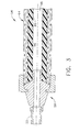
- FIG. 5 illustrates an alternate fitting for a fuse.
- an apparatus 10 such as a gas turbine engine for an aircraft, includes an engine component 12, such as a combustor.
- a signal tube 20 generally extends from the component 12 to the control mechanism 14.
- the signal tube may be operative, for example, to provide information concerning the pressure in the combustor.
- the signal tube contains generally static fluid, i.e., air.
- the pressure from the signal tube is input to the engine control or FADEC. Under current operating protocol, a loss of pressure signal to the engine control mechanism initiates an engine shutdown operation.
- an aircraft engine may employ one or more firewalls 22 to separate a fire-zone ("hot side") from a non-fire zone ("cool side").
- Aviation regulations and other requirements mandate that hot air or other gases should not enter the non-fire zone.
- some components on the cool side are formed of composite materials that are not rated for high temperature exposure.
- some components disposed on the cool side do not have insulation or other fire protection.
- the control mechanism or FADEC is disposed in a non-fire zone. In such designs, the signal tube 20 extends from the combustor on the hot side, to the control mechanism on the cool side.
- the static fluid in the signal tube 20 is generally at ambient temperature. If a break or other breach (improper connections, etc) were to occur in the signal tube 20, the usually static fluid contained therein would leak to the surroundings and hot fluid (air) from the combustor would begin flowing in the tube and leaking through the breach. If the break or other breach occurs in the non-fire zone, the leaking fluid would exceed allowable temperature requirements.
- engine 30 includes a signal tube 40 that extends between an engine component 42 on a hot side of a firewall 44 and an engine control mechanism 46 on a cool side of firewall 44.
- the exemplary signal tube 40 defines a flow path 48 therein.
- the signal tube 40 includes at least a first portion 50 extending on the hot side and a second portion 52 extending on the cool side.
- the signal tube 40 comprises shaped metal tubing 53 in operative connection with a substantially tubular fuse 54.
- Fuse 54 defines an inner pathway 56 forming a part of flow path 48.
- fuse 54 includes fittings 58 at each end which are adapted to engage fuse 54 with the metal tubing 53. Many options are available for engaging the fuse with the metal tubing and the fittings 58 are merely exemplary.
- An exemplary fuse 54 includes at least one inner member 60 disposed adjacent the flow path 48.
- the inner member 60 comprises a hose formed of a temperature-sensitive material.
- the temperature-sensitive material is deformable upon exposure to temperatures greater than a predetermined temperature.
- an exemplary temperature-sensitive material comprises polytetrafloroethylene (PTFE) which melts upon exposures greater than 600 °F (326 °C).
- the inner member 60 may comprise other temperature-sensitive materials such as brazing compounds.
- the inner member 60 is operative to deform or melt at temperatures less than typical temperatures of air in a combustor.
- the inner member 60 should melt or deform at temperatures less than about 1000 °F (538 °C). The melting or deforming temperature must be high enough that the inner member 60 remains intact during exposure to the ambient temperatures on the hot side.
- fuse 54 includes an outer member 64 substantially enclosing inner member 60.
- the outer member 64 comprises a metal braid so as to provide reinforcement and flexibility for fuse 54.
- the outer member 64 is operative to provide information about a condition of the fuse 54. For example, in an exemplary embodiment, an observer is able to perceive a condition of the fuse 54 upon visual perception of the outer member 64. Visual perception of the outer member 64 as shown in FIG. 3 shows that the fuse 54 is in a first condition having an operable pathway therethrough.
- the signal tube 40 when operable, provides a pressure signal to at least one engine control mechanism 46 or FADEC.
- the signal tube 40 essentially contains static fluid (air) at ambient temperature along the length of flow path 48.
- the second portion 52 which extends on the cool side of the firewall 44, is able to meet the imposed temperature requirements. If a break or other breach 70, shown in phantom, occurs in the signal tube 40, hot fluid (air) at about 1000°F (or greater) will flow through the signal tube 40 from the engine component 42, i.e., combustor, toward the breach.
- the inner member 60 if the breach is downstream of the fuse 54, eventually the inner member 60 will be exposed to temperatures greater than the predetermined temperature, i.e., about 600 °F (316 °C). Upon exposure to the elevated temperatures, the temperature-sensitive inner member 60 deforms (melts) and blocks fluid flow through flow path 48.
- the hot fluid flows through the outer member 64 into the surrounding environment on the hot side of the firewall 44.
- the outer member 64 exhibits discoloration or scorching 72 due to the passage of the hot fluid therethrough. Thus, visual inspection of the outer member 64 provides information about the condition of the fuse 54. In a second condition, the pathway 56 is obstructed.
- some melted material 74 may seep through the metal braid to provide visual information about the condition of the fuse 54. Because the hot fluid cannot flow to the second portion 52 of the signal tube, but is discharged on the hot side of the firewall, the second portion 52 (on the cool side) does not exceed temperature requirements.
- the engine control mechanism 46 is operable to use an alternative operating logic.
- the alternative operating logic allows engine operation without the pressure input from signal tube 40.
- FIG. 5 illustrates an alternate fitting 80 that may be employed in exemplary embodiments of fuse 54.
- a fitting 80 is merely exemplary and other alternative fittings may be used as will be appreciated by those with skill in the art.
- alternate logic may be employed in other situations where the pressure signal is not received. For example, frozen moisture in the signal tube may prevent receipt of the pressure signal. Rather than engine shut down, the engine could be operated under the alternate operating logic. Such alternate logics are currently known and may be utilized within the scope of this disclosure.
Landscapes
- Engineering & Computer Science (AREA)
- Mechanical Engineering (AREA)
- General Engineering & Computer Science (AREA)
- Chemical & Material Sciences (AREA)
- Combustion & Propulsion (AREA)
- Physics & Mathematics (AREA)
- General Physics & Mathematics (AREA)
- Fire-Extinguishing By Fire Departments, And Fire-Extinguishing Equipment And Control Thereof (AREA)
- Control Of Turbines (AREA)
Applications Claiming Priority (1)
| Application Number | Priority Date | Filing Date | Title |
|---|---|---|---|
| US11/646,003 US7434451B2 (en) | 2006-12-27 | 2006-12-27 | Method for preventing an over temperature condition in a gas turbine engine |
Publications (2)
| Publication Number | Publication Date |
|---|---|
| EP1972914A2 true EP1972914A2 (de) | 2008-09-24 |
| EP1972914A3 EP1972914A3 (de) | 2014-04-30 |
Family
ID=39551487
Family Applications (1)
| Application Number | Title | Priority Date | Filing Date |
|---|---|---|---|
| EP07123238.3A Withdrawn EP1972914A3 (de) | 2006-12-27 | 2007-12-14 | Verfahren zur Verhinderung eines Übertemperaturzustands in einem Gasturbinenmotor |
Country Status (4)
| Country | Link |
|---|---|
| US (1) | US7434451B2 (de) |
| EP (1) | EP1972914A3 (de) |
| JP (1) | JP5138358B2 (de) |
| CA (1) | CA2614417C (de) |
Families Citing this family (8)
| Publication number | Priority date | Publication date | Assignee | Title |
|---|---|---|---|---|
| US9482157B2 (en) | 2013-02-28 | 2016-11-01 | United Technologies Corporation | Bifurcation fire purge system for a gas turbine engine |
| GB201317924D0 (en) | 2013-10-10 | 2013-11-27 | Rolls Royce Plc | Gas turbine engine |
| US10047676B2 (en) | 2016-04-25 | 2018-08-14 | United Technologies Corporation | Electronic module mounting to vibration isolating structure |
| US10156188B2 (en) | 2016-04-25 | 2018-12-18 | United Technologies Corporation | Electronic module location for mechanical components |
| US10267236B2 (en) * | 2016-04-25 | 2019-04-23 | United Technologies Corporation | Electronic module mounting to vibration isolating structure |
| US10801361B2 (en) | 2016-09-09 | 2020-10-13 | General Electric Company | System and method for HPT disk over speed prevention |
| US20200248580A1 (en) * | 2019-02-05 | 2020-08-06 | United Technologies Corporation | Duct rupture detection system |
| US20210277782A1 (en) * | 2019-11-26 | 2021-09-09 | Solar Turbines Incorporated | Pressure capture canister |
Family Cites Families (7)
| Publication number | Priority date | Publication date | Assignee | Title |
|---|---|---|---|---|
| US2621239A (en) * | 1950-08-22 | 1952-12-09 | Photoswitch Inc | Heat detector for aircraft |
| US4194357A (en) * | 1976-07-13 | 1980-03-25 | The Garrett Corporation | Auto ignition temperature control system |
| US4657386A (en) * | 1985-11-14 | 1987-04-14 | United Technologies Corporation | In-flight engine control optical pyrometer |
| GB9017715D0 (en) * | 1990-08-13 | 1990-09-26 | Ici Plc | Low energy fuse |
| US5828797A (en) * | 1996-06-19 | 1998-10-27 | Meggitt Avionics, Inc. | Fiber optic linked flame sensor |
| US7437871B2 (en) * | 2002-05-31 | 2008-10-21 | General Electric Company | Automatic engine protection system for use when electronic parts of a control system are exposed to overtemperature conditions |
| US7191084B2 (en) * | 2005-04-20 | 2007-03-13 | General Electric Company | Method and apparatus for gas turbine engine ignition systems |
-
2006
- 2006-12-27 US US11/646,003 patent/US7434451B2/en active Active
-
2007
- 2007-12-13 CA CA2614417A patent/CA2614417C/en not_active Expired - Fee Related
- 2007-12-14 EP EP07123238.3A patent/EP1972914A3/de not_active Withdrawn
- 2007-12-26 JP JP2007333396A patent/JP5138358B2/ja not_active Expired - Fee Related
Non-Patent Citations (1)
| Title |
|---|
| None * |
Also Published As
| Publication number | Publication date |
|---|---|
| US7434451B2 (en) | 2008-10-14 |
| JP2008169833A (ja) | 2008-07-24 |
| US20080156089A1 (en) | 2008-07-03 |
| CA2614417C (en) | 2015-11-24 |
| JP5138358B2 (ja) | 2013-02-06 |
| EP1972914A3 (de) | 2014-04-30 |
| CA2614417A1 (en) | 2008-06-27 |
Similar Documents
| Publication | Publication Date | Title |
|---|---|---|
| CA2614434C (en) | Apparatus and system having an over temperature fuse in a signal tube for a gas turbine engine | |
| CA2614417C (en) | Method for preventing an over temperature condition in a gas turbine engine | |
| CN101443237B (zh) | 用于防止飞行器的引气供应系统过热的线路布置和包括这种线路布置的引气供应系统 | |
| US20100207379A1 (en) | Fluid conduit coupling with leakage detection | |
| EP4105468B1 (de) | Strömungsstrukturen für brennstoffsysteme | |
| EP2157298B1 (de) | Verfahren zur Erkennung von Überdruck in einer Kammer, die mit einer Gasturbinentriebwerksgondel verbunden ist | |
| CA2591454C (en) | Low-cost frangible cable for gas turbine engine | |
| JP6585699B2 (ja) | 密閉手段を含んだ航空機タービンエンジンに設置される加圧空気を供給するためのシステム | |
| CN107109959A (zh) | 检测涡轮机中流体泄漏的方法及流体分配系统 | |
| EP3858736B1 (de) | Pneumatisches flugzeugsystem | |
| EP3693557B1 (de) | System zur detektion von kanalbrüchen | |
| EP3954877B1 (de) | System und verfahren zur erkennung von übermässiger strömung in einem flüssigkeitssystem | |
| US20110020543A1 (en) | Method For Installing Function Monitoring Means In A Flow Machine Installation | |
| EP3171144A1 (de) | Instrumentierungsadapter für einen gasturbinenmotor | |
| US12523175B1 (en) | Flame protection seals for gas turbine engines | |
| GB2635150A (en) | Aeroengine and process of operating an aeroengine | |
| US20110060482A1 (en) | Control assembly | |
| JPH11336928A (ja) | ガス保安システム | |
| ARP1796 | REV. A | |
| JPH11339146A (ja) | ガス保安システム |
Legal Events
| Date | Code | Title | Description |
|---|---|---|---|
| PUAI | Public reference made under article 153(3) epc to a published international application that has entered the european phase |
Free format text: ORIGINAL CODE: 0009012 |
|
| AK | Designated contracting states |
Kind code of ref document: A2 Designated state(s): AT BE BG CH CY CZ DE DK EE ES FI FR GB GR HU IE IS IT LI LT LU LV MC MT NL PL PT RO SE SI SK TR |
|
| AX | Request for extension of the european patent |
Extension state: AL BA HR MK RS |
|
| RIC1 | Information provided on ipc code assigned before grant |
Ipc: G01K 11/06 20060101AFI20140213BHEP |
|
| RIC1 | Information provided on ipc code assigned before grant |
Ipc: G01K 11/06 20060101AFI20140214BHEP |
|
| PUAL | Search report despatched |
Free format text: ORIGINAL CODE: 0009013 |
|
| RIC1 | Information provided on ipc code assigned before grant |
Ipc: G01K 11/06 20060101AFI20140317BHEP |
|
| AK | Designated contracting states |
Kind code of ref document: A3 Designated state(s): AT BE BG CH CY CZ DE DK EE ES FI FR GB GR HU IE IS IT LI LT LU LV MC MT NL PL PT RO SE SI SK TR |
|
| AX | Request for extension of the european patent |
Extension state: AL BA HR MK RS |
|
| 17P | Request for examination filed |
Effective date: 20141030 |
|
| RBV | Designated contracting states (corrected) |
Designated state(s): AT BE BG CH CY CZ DE DK EE ES FI FR GB GR HU IE IS IT LI LT LU LV MC MT NL PL PT RO SE SI SK TR |
|
| AKX | Designation fees paid |
Designated state(s): DE FR GB |
|
| AXX | Extension fees paid |
Extension state: MK Extension state: BA Extension state: AL Extension state: HR Extension state: RS |
|
| 17Q | First examination report despatched |
Effective date: 20171027 |
|
| STAA | Information on the status of an ep patent application or granted ep patent |
Free format text: STATUS: THE APPLICATION IS DEEMED TO BE WITHDRAWN |
|
| 18D | Application deemed to be withdrawn |
Effective date: 20180307 |