EP1972828A2 - Drehschwingungsdämpfer - Google Patents
Drehschwingungsdämpfer Download PDFInfo
- Publication number
- EP1972828A2 EP1972828A2 EP08003332A EP08003332A EP1972828A2 EP 1972828 A2 EP1972828 A2 EP 1972828A2 EP 08003332 A EP08003332 A EP 08003332A EP 08003332 A EP08003332 A EP 08003332A EP 1972828 A2 EP1972828 A2 EP 1972828A2
- Authority
- EP
- European Patent Office
- Prior art keywords
- damping
- torsional vibration
- vibration damper
- plastic
- hub
- Prior art date
- Legal status (The legal status is an assumption and is not a legal conclusion. Google has not performed a legal analysis and makes no representation as to the accuracy of the status listed.)
- Granted
Links
Images




Classifications
-
- F—MECHANICAL ENGINEERING; LIGHTING; HEATING; WEAPONS; BLASTING
- F16—ENGINEERING ELEMENTS AND UNITS; GENERAL MEASURES FOR PRODUCING AND MAINTAINING EFFECTIVE FUNCTIONING OF MACHINES OR INSTALLATIONS; THERMAL INSULATION IN GENERAL
- F16F—SPRINGS; SHOCK-ABSORBERS; MEANS FOR DAMPING VIBRATION
- F16F15/00—Suppression of vibrations in systems; Means or arrangements for avoiding or reducing out-of-balance forces, e.g. due to motion
- F16F15/10—Suppression of vibrations in rotating systems by making use of members moving with the system
- F16F15/12—Suppression of vibrations in rotating systems by making use of members moving with the system using elastic members or friction-damping members, e.g. between a rotating shaft and a gyratory mass mounted thereon
- F16F15/121—Suppression of vibrations in rotating systems by making use of members moving with the system using elastic members or friction-damping members, e.g. between a rotating shaft and a gyratory mass mounted thereon using springs as elastic members, e.g. metallic springs
- F16F15/123—Wound springs
- F16F15/1238—Wound springs with pre-damper, i.e. additional set of springs between flange of main damper and hub
Definitions
- the invention relates to a torsional vibration damper having a main damping device and a pre-damping device which is effective up to a pre-damping angle and comprises a pre-damping flange, which is coupled on the one hand to first coupling points with pre-damping spring elements and on the other hand to a hub device at second coupling points.
- the object of the invention is to provide a torsional vibration damper according to the preamble of claim 1, which has a longer life than conventional torsional vibration damper.
- the object is achieved in a torsional vibration damper with a main damping device and a pre-damping device which is effective up to a pre-damping angle and a Vordämpfungsflansch coupled on the one hand at first coupling points with Vordämpfungsfeder instituten and on the other hand at second coupling points with a hub device, achieved in that the friction pairings of Contact partner at the first and / or second coupling points are optimized in terms of friction.
- the torque is introduced from the pre-damping device via the pre-damping spring elements and the pre-damping flange into the hub device.
- the torque is introduced into the hub device only via the main damping device, preferably past the pre-damping device.
- the wear can be significantly reduced without compromising the strength of the pre-damper flange, which could be the case, for example, with an embodiment of the plastic pre-damper flange.
- a preferred embodiment of the torsional vibration damper is characterized in that in each case at least one of the contact partners is formed at the first and / or second coupling points of a low-friction material, in particular of plastic.
- low-friction means that in a friction pairing of the low-friction material with a relatively hard material, such as steel, only low friction occurs.
- the friction pairing is preferably designed so that the friction coefficient is significantly reduced in comparison with a steel / steel friction pairing.
- the friction pairings are designed as plastic / steel friction pairings.
- a further preferred embodiment of the torsional vibration damper is characterized in that the pre-damping flange made of metal, in particular of steel, formed and reinforced at the first and / or second coupling points with plastic.
- the plastic reinforcement prevents two steel contact partners from coming into contact with each other.
- a further preferred embodiment of the torsional vibration damper is characterized in that the pre-damping flange has an internal toothing, which engages in an external toothing of the hub device and is surrounded by a plastic part, in particular a plastic ring.
- the plastic part or the plastic ring may also be provided on the hub device.
- a further preferred embodiment of the torsional vibration damper is characterized in that the plastic part or the plastic ring is clipped into the internal toothing of the pre-damping flange.
- the shape of the plastic part or the plastic ring is adapted to the shape of the internal toothing of the pre-damping flange.
- a further preferred embodiment of the torsional vibration damper is characterized in that the internal toothing of the pre-damping flange is encapsulated in plastic. Preferably, only the areas of the internal toothing of the pre-damping flange are encapsulated with plastic, to which a contact partner made of steel comes into contact.
- the torsional vibration damper is characterized in that the pre-damping flange for coupling with the pre-damping spring elements has windows which are reinforced with plastic at the first coupling points.
- a plastic element may be clipped into the windows.
- the windows can also, at least partially, be encapsulated in plastic.
- a further preferred embodiment of the torsional vibration damper is characterized in that the pre-damping spring elements made of metal, in particular spring steel, formed and reinforced at the first coupling points with plastic.
- the ends of the pre-damping spring elements, which come into contact with the pre-damping flange, are reinforced with plastic.
- a further preferred embodiment of the torsional vibration damper is characterized in that plastic cups are attached to the pre-damping spring elements.
- the pre-damping spring elements are preferably helical compression springs.
- the plastic cups are clipped into the ends of the helical compression springs.
- a further preferred embodiment of the torsional vibration damper is characterized in that the torsional vibration damper comprises two side parts which are non-rotatably connected and between which at least one intermediate part, in particular two intermediate parts, is or are arranged, which limits or relative to the side parts against the spring action of spring devices are rotatable.
- the pre-damping device can be constructed symmetrically or asymmetrically.
- the pre-damping device may comprise a plurality of pre-attenuation stages. The pre-damping device develops its effect up to a certain angle of rotation, which is referred to as pre-attenuation angle. At the pre-attenuation angle a certain moment acts.
- the pre-damping device After exceeding the pre-damping angle, the pre-damping device switches off and the spring devices, which are also referred to as the main damping device, develop their main damping effect up to a main damping angle.
- the main damping device By combining the main damping device with the pre-damping device, the damping behavior can be significantly improved.
- the spring means of the main damping device are arranged in the torsional vibration damper according to the invention within windows which are recessed in both the side parts and in the intermediate part or the intermediate parts.
- the windows in the intermediate parts have in the circumferential direction on one side in each case a guide nose and on the other side in each case a recess in which a guide nose of the respective other intermediate part is arranged.
- the guide lugs unfold their guiding effect only in one load direction, that is to say under tensile or shear loading.
- the recesses allow a simple way a movement of the intermediate parts with the guide lugs relative to each other.
- the guide lugs allow a wear-free guidance of the spring means of the main damping device.
- the spring devices are preferably compression springs, which are designed as helical compression springs. According to one essential aspect of the invention, the concept of wear-free spring guide is combined with a pre-damping device.
- a preferred embodiment of the torsional vibration damper is characterized in that in each case a spacer pin, which is fixedly connected to the side parts, extends through the recesses of the window.
- the spacer bolts serve to arrange the side parts in the axial direction at a defined distance from each other. About the standoffs torque is transmitted from the side parts depending on the load direction on one of the intermediate parts.
- the spacer bolts form a stop for each intermediate part in the circumferential direction.
- the shape of the recesses is adapted to the shape of the spacer bolts.
- the intermediate parts each comprise a hub flange which is coupled to a hub.
- the hub is non-rotatably connected to a transmission input shaft.
- a further preferred embodiment of the torsional vibration damper is characterized in that the hub is provided with an external toothing, which cooperates with an internal toothing of the intermediate parts. This allows the transmission of torque from the intermediate parts to the hub.
- a further preferred embodiment of the torsional vibration damper is characterized in that between the outer toothing of the hub and the internal teeth of the intermediate parts in the circumferential direction a defined game is present.
- the hub is rotatably connected with its outer teeth with one or the other intermediate part.
- a further preferred embodiment of the torsional vibration damper is characterized in that the guide projections each extend from a plane in which the associated intermediate part expands in the direction of a longitudinal axis of the associated spring device.
- a further preferred exemplary embodiment of the torsional vibration damper is characterized in that the spring devices each comprise at least one helical spring element with two ends, in each of which one of the guide lugs engages.
- the coil spring element can also be encompassed externally by a guide element.
- a further preferred embodiment of the torsional vibration damper is characterized in that the spring means each comprise an outer and an inner coil spring element with two ends, in each of which engages one of the guide lugs.
- the outer coil spring element is guided over the inner coil spring element by the guide lugs.
- a further preferred embodiment of the torsional vibration damper is characterized in that the guide lugs are integrally connected to the associated intermediate part.
- the intermediate part is preferably a sheet metal part from which the guide lugs are stamped out.
- a further preferred exemplary embodiment of the torsional vibration damper is characterized in that the pre-damping device comprises an intermediate hub which can be connected in a rotationally fixed manner to one or the hub with a defined pre-damping twisting lash.
- the intermediate hub is arranged in the radial direction between the hub and the intermediate part or the intermediate parts.
- a further preferred embodiment of the torsional vibration damper is characterized in that the defined pre-damping twisting play corresponds to twice the value of the pre-damping angle.
- the pre-attenuation angle is the same in both directions of rotation.
- a further preferred embodiment of the torsional vibration damper is characterized in that the defined pre-damping twisting play is provided between an external toothing of the hub and an internal toothing of the intermediate hub. After overcoming the defined Vordämpfungsverfitspiels the gears of the hub and the intermediate hub come together in abutment so that a rotationally fixed connection between the hub and the intermediate hub is created.
- a further preferred embodiment of the torsional vibration damper is characterized in that the intermediate hub with a defined clearance angle rotation with at least one of the intermediate parts is connectable.
- the clearance angle results from the difference between the or a main damping angle and the pre-damping angle.
- a further preferred embodiment of the torsional vibration damper is characterized in that the clearance angle is predetermined by a main damping twisting clearance between an external toothing of the intermediate hub and an internal toothing of the at least one intermediate part. After overcoming the clearance angle or the Hauptdämpfungsverfitspiels the teeth of the intermediate hub and the at least one intermediate part come into abutment against each other so that a rotationally fixed connection between the intermediate hub and the at least one intermediate part is created.
- a further preferred embodiment of the torsional vibration damper is characterized in that the pre-damping device comprises a pre-damping housing, in which a pre-damping flange is coupled to the pre-damping housing with the interposition of pre-damping spring elements. At angles of rotation smaller than the pre-damping angle, the moment is transmitted from the pre-damper housing to the pre-damper flange via the pre-damper spring elements.
- a further preferred embodiment of the torsional vibration damper is characterized in that the pre-damping flange is connected to the hub with virtually no play. In this case, it means virtually no play, that there is at most a small joining game. For angles of rotation greater than the pre-attenuation angle, torque is transmitted directly from the intermediate hub to the hub.
- a further preferred embodiment of the torsional vibration damper is characterized in that the pre-damping flange has an internal toothing, which is in engagement with one or the outer toothing of the hub.
- the teeth of the gears of the hub and the pre-damping flange are distributed uniformly over the circumference.
- Another preferred embodiment of the torsional vibration damper is characterized in that the pre-damper housing virtually without circumferential play with the intermediate hub connected is. In this case, it means virtually no play, that there is at most a small joining game.
- a further preferred embodiment of the torsional vibration damper is characterized in that the pre-damping housing comprises two pre-damping cages which are non-rotatably connected to one another.
- the pre-damping cages are preferably designed as identical parts to save tooling costs. But the pre-damping cages can also be designed differently and are, for example by pins and holes, preferably positively connected to each other.
- a further preferred embodiment of the torsional vibration damper is characterized in that one of the pre-damping cages has an internal toothing, which is in engagement with an external toothing of the intermediate hub.
- the teeth of the teeth of the intermediate hub and the pre-damping cage are distributed uniformly over the circumference.
- a further preferred embodiment of the torsional vibration damper is characterized in that the pre-damping device is arranged between one of the side parts and the intermediate part or one of the intermediate parts that in a main damping operation in a load direction, in particular tensile load, more friction points than in the other load direction, in particular at Shear load, are effective.
- a larger friction damping / hysteresis is possible in the train operation.
- a better vibration isolation is possible in overrun mode.
- a further preferred embodiment of the torsional vibration damper is characterized in that the pre-damping device is arranged between one of the side parts and the intermediate part or one of the intermediate parts such that in a main damping operation in a load direction, in particular under tensile load, twice as many friction points as in the other load direction, especially under shear load, are effective.
- On specially integrated friction control discs can be omitted.
- four friction points are effective in the case of tensile load and two friction points in the case of shear loading.
- the invention further relates to a clutch disc with a previously described torsional vibration damper.
- the invention is particularly suitable for clutch discs of commercial vehicles and passenger cars with heavy main damper springs.
- FIG. 1 is in a Cartesian coordinate diagram transmitted from the clutch disc torque M in Nm above the angle of rotation ⁇ in degrees in Plotted form of a characteristic.
- the characteristic curve is shown in a twisting direction.
- the characteristic curve can be symmetrical or asymmetrical in both directions of rotation.
- the characteristic in the illustrated direction of rotation comprises a first characteristic section I, in which a pre-damping device is integrated, which is integrated in the clutch disc.
- the pre-damping device develops its effect up to a pre-damping angle ⁇ 1 .
- the moment M1 acts, which is also referred to as pre-damping torque.
- the pre-damping device switches off and acts as a main damping device integrated into the clutch disc.
- the main damping device acts up to a main damping angle ⁇ 2 .
- the associated stop torque is designated M2.
- FIGS. 2 and 3 is a clutch disc 1 with wear-free main damper guide and integrated pre-damping device in plan view and shown in section.
- a torsional vibration damper 2 is integrated.
- Radially inside the clutch disc 1 comprises a hub device 3, which comprises a hub 4 with an internal toothing 5.
- the internal toothing 5 serves to connect the clutch disc 1 in the drive train of a motor vehicle rotatably with a transmission input shaft.
- the hub device 3 comprises, in addition to the hub 4, an intermediate hub 6.
- the intermediate hub 6 is designed as a separate component.
- the hub device 3 is rotatably connected to two intermediate parts 11, 12 connectable.
- the intermediate parts 11, 12 extend in a flange-like manner in the radial direction and are therefore also referred to as hub flanges or short flanges.
- the terms radial, axial and in the circumferential direction in the context of the present invention refer to a rotation axis 13 of the clutch disc 1.
- bearing means 14, 15 are two side parts 21, 22 relative to the hub device 3 and the intermediate parts 11, 12 against the action of at least one spring means 23 rotatable limited, which is also referred to as the main damping device.
- the spring device 23 comprises in the circumferential direction evenly distributed four spring elements 24, 25, 26 and 27.
- the twist angle is limited by spacer bolts 28 which are fixed to the side parts 21, 22 and extend through the intermediate parts 11, 12 therethrough.
- the spacer bolts 28 are preferably designed as a stepped bolt and riveted to the side parts 21, 22.
- the intermediate parts 11, 12 are arranged in the axial direction between the side parts 21, 22.
- a pad carrier disk 30 with two friction lining halves 31, 32 is attached radially on the outside.
- the friction device 40 comprises at least one disc spring and at least one friction ring.
- a pre-damping device 44 is integrated into the clutch disk 1 or the torsional vibration damping device 2.
- the pre-damping device 44 comprises a pre-damping housing 45, which is arranged in the axial direction between the side part 21 and the intermediate part 11.
- a pre-damping flange 46 is arranged in the pre-damping housing 45.
- the pre-damping flange 46 is rotatable relative to two pre-damping cages 48, 49 which form the pre-damper housing 45.
- the pre-damping flange 46 is rotatable against the action of a pre-damper spring means 50 disposed in the pre-damper housing 45.
- FIG. 8 is the view of a section along the line VIII-VIII FIG. 7 represented by the FIG. 6 equivalent.
- the intermediate hub 6 has an outer toothing 51, which cooperates with an internal toothing 52, which is provided on the intermediate part 11.
- an internal toothing 52 which is provided on the intermediate part 11.
- a further internal toothing 53 is provided, which also cooperates with the external toothing 51 of the intermediate hub 6.
- FIG. 9 is a section of FIG. 8 shown enlarged.
- the backlash which is provided between the outer teeth 51 of the intermediate hub 6 and the internal teeth 52 of the intermediate part 11.
- the torsional backlash 55 results from the difference between the main damping angle ⁇ 2 and the pre-damping angle ⁇ 1 .
- the springs 24, 25, 26, 27 in FIG. 8 are also referred to as main damper compression springs and serve to transmit the moment depending on the direction of rotation on one of the intermediate parts 11, 12.
- the intermediate parts 11, 12 are coupled together by the main damper springs 24 to 27.
- a pre-damping device 104 according to the invention is shown in cross-section and in longitudinal section.
- the pre-damper 104 includes a pre-damper housing 105 in which a pre-damper flange 106 is disposed.
- the pre-damping flange 106 is rotatable relative to two pre-damping cages 108, 109 that form the pre-damper housing 105.
- the pre-damper flange 106 is rotatable against the action of a pre-damper spring device 110 disposed in the pre-damper housing 105.
- the pre-damping spring device 110 comprises four pre-damping spring elements 116, 117, 118 and 119. At angles of rotation that are smaller than the pre-damping angle, the torque is transmitted via the pre-damping spring elements 116 to 119, which are preferably designed as helical compression springs, on the pre-damping flange 106, the quasi backlash-free rotation with the hub (4 in the FIGS. 3 to 8 ) connected is. For angles of rotation greater than the pre-attenuation angle, the moment is measured directly from the intermediate hub (6 in FIGS FIGS. 3 to 8 ) transferred to the hub.
- the two pre-damping cages 108, 109 transmit the moment to the pre-damping spring elements 116 to 119.
- the pre-damping spring elements 116 to 119 are reinforced at their ends with Kunststoffnäpfen 128, 129.
- the pre-damping spring elements 116 to 119 are preferably helical compression springs made of spring steel.
- the pre-damping flange 106 is preferably formed of steel.
- the plastic cups 128, 129 transmit the moment to the pre-damping flange 106.
- plastic inserts can also be clipped or sprayed into the windows of the pre-damping flange 106.
- a likewise toothed and advantageously provided with approximately constant wall thickness plastic part 124 is clipped or injected into the internal teeth 122 of the pre-damping flange 106.
- the plastic part 124 serves to produce a low-friction contact with the hub teeth.
- FIG. 12 is the pre-damper 104 from the FIGS. 10 and 11 shown in exploded view.
- the measures described above which relate to the reinforcement of steel parts with plastic, serve to reduce the micro-movements caused contact wear between the pre-damping flange 106 and its contact partners.
Landscapes
- Engineering & Computer Science (AREA)
- General Engineering & Computer Science (AREA)
- Physics & Mathematics (AREA)
- Acoustics & Sound (AREA)
- Aviation & Aerospace Engineering (AREA)
- Mechanical Engineering (AREA)
- Mechanical Operated Clutches (AREA)
Abstract
Description
- Die Erfindung betrifft einen Drehschwingungsdämpfer mit einer Hauptdämpfungseinrichtung und einer Vordämpfungseinrichtung, die bis zu einem Vordämpfungswinkel wirksam ist und einen Vordämpfungsflansch umfasst, der einerseits an ersten Kopplungsstellen mit Vordämpfungsfederelementen und andererseits an zweiten Kopplungsstellen mit einer Nabeneinrichtung gekoppelt ist.
- Aufgabe der Erfindung ist es, einen Drehschwingungsdämpfer gemäß dem Oberbegriff des Anspruchs 1 zu schaffen, der eine längere Lebensdauer als herkömmliche Drehschwingungsdämpfer aufweist.
- Die Aufgabe ist bei einem Drehschwingungsdämpfer mit einer Hauptdämpfungseinrichtung und einer Vordämpfungseinrichtung, die bis zu einem Vordämpfungswinkel wirksam ist und einen Vordämpfungsflansch umfasst, der einerseits an ersten Kopplungsstellen mit Vordämpfungsfederelementen und andererseits an zweiten Kopplungsstellen mit einer Nabeneinrichtung gekoppelt ist, dadurch gelöst, dass die Reibpaarungen der Kontaktpartner an den ersten und/oder zweiten Kopplungsstellen im Hinblick auf Reibung optimiert sind. Bei Verdrehwinkeln, die kleiner als ein Vordämpfungswinkel sind, wird das Moment von der Vordämpfungseinrichtung über die Vordämpfungsfederelemente und den Vordämpfungsflansch in die Nabeneinrichtung eingeleitet. Bei Verdrehwinkeln, die größer als der Vordämpfungswinkel sind, wird das Moment nur über die Hauptdämpfungseinrichtung, vorzugsweise an der Vordämpfungseinrichtung vorbei, in die Nabeneinrichtung eingeleitet. Durch die Optimierung der Reibpaarungen der Kontaktpartner kann der Verschleiß deutlich reduziert werden, ohne dass die Festigkeit des Vordämpfungsflanschs beeinträchtigt wird, was zum Beispiel bei einer Ausführung des Vordämpfungsflanschs aus Kunststoff der Fall sein könnte.
- Ein bevorzugtes Ausführungsbeispiel des Drehschwingungsdämpfers ist dadurch gekennzeichnet, dass jeweils mindestens einer der Kontaktpartner an den ersten und/oder zweiten Kopplungsstellen aus einem reibungsarmen Material, insbesondere aus Kunststoff, gebildet ist. Dabei bedeutet reibungsarm, dass bei einer Reibpaarung des reibungsarmen Materials mit einem relativ harten Material, wie Stahl, nur geringe Reibung auftritt. Die Reibpaarung wird vorzugsweise so ausgelegt, dass der Reibungskoeffizient im Vergleich mit einer Stahl/Stahl-Reibpaarung deutlich reduziert ist. Besonders bevorzugt sind die Reibpaarungen als Kunststoff/Stahl-Reibpaarungen ausgeführt.
- Ein weiteres bevorzugtes Ausführungsbeispiel des Drehschwingungsdämpfers ist dadurch gekennzeichnet, dass der Vordämpfungsflansch aus Metall, insbesondere aus Stahl, gebildet und an den ersten und/oder zweiten Kopplungsstellen mit Kunststoff bewehrt ist. Durch die Kunststoffbewehrung wird verhindert, dass zwei Kontaktpartner aus Stahl aneinander zur Anlage kommen.
- Ein weiteres bevorzugtes Ausführungsbeispiel des Drehschwingungsdämpfers ist dadurch gekennzeichnet, dass der Vordämpfungsflansch eine Innenverzahnung aufweist, die in eine Außenverzahnung der Nabeneinrichtung eingreift und mit einem Kunststoffteil, insbesondere einem Kunststoffring, umgeben ist. Alternativ kann das Kunststoffteil oder der Kunststoffring auch an der Nabeneinrichtung vorgesehen sein.
- Ein weiteres bevorzugtes Ausführungsbeispiel des Drehschwingungsdämpfers ist dadurch gekennzeichnet, dass das Kunststoffteil oder der Kunststoffring in die Innenverzahnung des Vordämpfungsflanschs eingeklipst ist. Vorzugsweise ist die Gestalt Kunststoffteils oder des Kunststoffrings an die Gestalt der Innenverzahnung des Vordämpfungsflanschs angepasst.
- Ein weiteres bevorzugtes Ausführungsbeispiel des Drehschwingungsdämpfers ist dadurch gekennzeichnet, dass die Innenverzahnung des Vordämpfungsflanschs mit Kunststoff umspritzt ist. Vorzugsweise sind nur die Bereiche der Innenverzahnung des Vordämpfungsflanschs mit Kunststoff umspritzt, an denen ein Kontaktpartner aus Stahl zur Anlage kommt.
- Ein weiteres bevorzugtes Ausführungsbeispiel des Drehschwingungsdämpfers ist dadurch gekennzeichnet, dass der Vordämpfungsflansch zur Kopplung mit den Vordämpfungsfederelementen Fenster aufweist, die an den ersten Kopplungsstellen mit Kunststoff bewehrt sind. Zu diesem Zweck kann ein Kunststoffelement in die Fenster eingeklipst sein. Die Fenster können aber auch, zumindest teilweise, mit Kunststoff umspritzt sein.
- Ein weiteres bevorzugtes Ausführungsbeispiel des Drehschwingungsdämpfers ist dadurch gekennzeichnet, dass die Vordämpfungsfederelemente aus Metall, insbesondere aus Federstahl, gebildet und an den ersten Kopplungsstellen mit Kunststoff bewehrt sind. Vorzugsweise sind die Enden der Vordämpfungsfederelemente, die mit dem Vordämpfungsflansch in Kontakt kommen, mit Kunststoff bewehrt.
- Ein weiteres bevorzugtes Ausführungsbeispiel des Drehschwingungsdämpfers ist dadurch gekennzeichnet, dass an den Vordämpfungsfederelementen Kunststoffnäpfe befestigt sind. Bei den Vordämpfungsfederelementen handelt es sich vorzugsweise um Schraubendruckfedern. Vorzugsweise sind die Kunststoffnäpfe in die Enden der Schraubendruckfedern eingeklipst.
- Ein weiteres bevorzugtes Ausführungsbeispiel des Drehschwingungsdämpfers ist dadurch gekennzeichnet, dass der Drehschwingungsdämpfer zwei Seitenteile umfasst, die drehfest miteinander verbunden und zwischen denen mindestens ein Zwischenteil, insbesondere zwei Zwischenteile, angeordnet ist beziehungsweise sind, das beziehungsweise die relativ zu den Seitenteilen entgegen der Federwirkung von Federeinrichtungen begrenzt verdrehbar sind. Die Vordämpfungseinrichtung kann symmetrisch oder unsymmetrisch aufgebaut sein. Des Weiteren kann die Vordämpfungseinrichtung mehrere Vordämpfungsstufen umfassen. Die Vordämpfungseinrichtung entfaltet ihre Wirkung bis zu einem bestimmten Verdrehwinkel, der als Vordämpfungswinkel bezeichnet wird. Bei dem Vordämpfungswinkel wirkt ein bestimmtes Moment. Nach Überschreiten des Vordämpfungswinkels schaltet die Vordämpfungseinrichtung ab und die Federeinrichtungen, die auch als Hauptdämpfungseinrichtung bezeichnet werden, entfalten bis zu einem Hauptdämpfungswinkel ihre Hauptdämpfungswirkung. Durch die Kombination der Hauptdämpfungseinrichtung mit der Vordämpfungseinrichtung kann das Dämpfungsverhalten deutlich verbessert werden.
- Vorzugsweise sind die Federeinrichtungen der Hauptdämpfungseinrichtung bei dem erfindungsgemäßen Drehschwingungsdämpfer innerhalb von Fenstern angeordnet, die sowohl in den Seitenteilen als auch in dem Zwischenteil beziehungsweise den Zwischenteilen ausgespart sind. Die Fenster in den Zwischenteilen weisen in Umfangsrichtung auf der einen Seite jeweils eine Führungsnase und auf der anderen Seite jeweils eine Ausnehmung auf, in der eine Führungsnase des jeweils anderen Zwischenteils angeordnet ist. Die Führungsnasen entfalten ihre Führungswirkung jeweils nur in einer Lastrichtung, das heißt bei Zug- oder Schubbelastung. Die Ausnehmungen ermöglichen auf einfache Art und Weise eine Bewegung der Zwischenteile mit den Führungsnasen relativ zueinander. Die Führungsnasen ermöglichen eine verschleißfreie Führung der Federeinrichtungen der Hauptdämpfungseinrichtung. Bei den Federeinrichtungen handelt es sich vorzugsweise um Druckfedern, die als Schraubendruckfedern ausgeführt sind. Gemäß einem wesentlichen Aspekt der Erfindung wird das Konzept der verschleißfreien Federführung mit einer Vordämpfungseinrichtung kombiniert.
- Ein bevorzugtes Ausführungsbeispiel des Drehschwingungsdämpfers ist dadurch gekennzeichnet, dass sich jeweils ein Abstandsbolzen, der fest mit den Seitenteilen verbunden ist, durch die Ausnehmungen der Fenster hindurch erstreckt. Die Abstandbolzen dienen dazu, die Seitenteile in axialer Richtung in einem definierten Abstand zueinander anzuordnen. Über die Abstandsbolzen wird ein Drehmoment von den Seitenteilen in Abhängigkeit von der Lastrichtung auf eines der Zwischenteile übertragen.
- Ein weiteres bevorzugtes Ausführungsbeispiel des Drehschwingungsdämpfers ist dadurch gekennzeichnet, dass die Abstandsbolzen in Umfangsrichtung einen Anschlag für jeweils ein Zwischenteil bilden. Vorzugsweise ist die Gestalt der Ausnehmungen an die Gestalt der Abstandsbolzen angepasst.
- Ein weiteres bevorzugtes Ausführungsbeispiel des Drehschwingungsdämpfers ist dadurch gekennzeichnet, dass die Zwischenteile jeweils einen Nabenflansch umfassen, der mit einer Nabe gekoppelt ist. Vorzugsweise ist die Nabe drehfest mit einer Getriebeeingangswelle verbunden.
- Ein weiteres bevorzugtes Ausführungsbeispiel des Drehschwingungsdämpfers ist dadurch gekennzeichnet, dass die Nabe mit einer Außenverzahnung versehen ist, die mit einer Innenverzahnung der Zwischenteile zusammenwirkt. Dadurch wird die Übertragung eines Drehmoments von den Zwischenteilen auf die Nabe ermöglicht.
- Ein weiteres bevorzugtes Ausführungsbeispiel des Drehschwingungsdämpfers ist dadurch gekennzeichnet, dass zwischen der Außenverzahnung der Nabe und der Innenverzahnung der Zwischenteile in Umfangsrichtung ein definiertes Spiel vorhanden ist. Je nach Lastrichtung ist die Nabe mit ihrer Außenverzahnung mit dem einen oder dem anderen Zwischenteil drehfest verbunden.
- Ein weiteres bevorzugtes Ausführungsbeispiel des Drehschwingungsdämpfers ist dadurch gekennzeichnet, dass sich die Führungsnasen jeweils aus einer Ebene, in der sich das zugehörige Zwischenteil ausdehnt, in Richtung einer Längsachse der zugehörigen Federeinrichtung erstreckt. Dadurch können Axialkraftkomponenten, die durch einen außermittigen Kraftangriff auf die Federeinrichtungen entstehen und zu einem seitlichen Auswandern/Ausknicken der Federeinrichtungen führen könnten, kompensiert werden.
- Ein weiteres bevorzugtes Ausführungsbeispiel des Drehschwingungsdämpfers ist dadurch gekennzeichnet, dass die Federeinrichtungen jeweils mindestens ein Schraubenfederelement mit zwei Enden umfassen, in die jeweils eine der Führungsnasen eingreift. Alternativ kann das Schraubenfederelement auch außen von einem Führungselement umgriffen werden.
- Ein weiteres bevorzugtes Ausführungsbeispiel des Drehschwingungsdämpfers ist dadurch gekennzeichnet, dass die Federeinrichtungen jeweils ein äußeres und ein inneres Schraubenfederelement mit zwei Enden umfassen, in die jeweils eine der Führungsnasen eingreift. Das äußere Schraubenfederelement ist über das innere Schraubenfederelement durch die Führungsnasen geführt.
- Ein weiteres bevorzugtes Ausführungsbeispiel des Drehschwingungsdämpfers ist dadurch gekennzeichnet, dass die Führungsnasen einstückig mit dem zugehörigen Zwischenteil verbunden sind. Bei dem Zwischenteil handelt es sich vorzugsweise um ein Blechteil, aus dem die Führungsnasen herausgeprägt sind.
- Ein weiteres bevorzugtes Ausführungsbeispiel des Drehschwingungsdämpfers ist dadurch gekennzeichnet, dass die Vordämpfungseinrichtung eine Zwischennabe umfasst, die mit einem definierten Vordämpfungsverdrehspiel drehfest mit einer beziehungsweise der Nabe verbindbar ist. Die Zwischennabe ist in radialer Richtung zwischen der Nabe und dem Zwischenteil beziehungsweise den Zwischenteilen angeordnet.
- Ein weiteres bevorzugtes Ausführungsbeispiel des Drehschwingungsdämpfers ist dadurch gekennzeichnet, dass das definierte Vordämpfungsverdrehspiel dem zweifachen Wert des Vordämpfungswinkels entspricht. Vorzugsweise ist der Vordämpfungswinkel in beiden Drehrichtungen gleich.
- Ein weiteres bevorzugtes Ausführungsbeispiel des Drehschwingungsdämpfers ist dadurch gekennzeichnet, dass das definierte Vordämpfungsverdrehspiel zwischen einer Außenverzahnung der Nabe und einer Innenverzahnung der Zwischennabe vorgesehen ist. Nach Überwinden des definierten Vordämpfungsverdrehspiels kommen die Verzahnungen der Nabe und der Zwischennabe aneinander so in Anschlag, dass eine drehfeste Verbindung zwischen der Nabe und der Zwischennabe geschaffen wird.
- Ein weiteres bevorzugtes Ausführungsbeispiel des Drehschwingungsdämpfers ist dadurch gekennzeichnet, dass die Zwischennabe mit einem definierten Freiwinkel drehfest mit mindestens einem der Zwischenteile verbindbar ist. Der Freiwinkel ergibt sich aus der Differenz zwischen dem beziehungsweise einem Hauptdämpfungswinkel und dem Vordämpfungswinkel.
- Ein weiteres bevorzugtes Ausführungsbeispiel des Drehschwingungsdämpfers ist dadurch gekennzeichnet, dass der Freiwinkel durch ein Hauptdämpfungsverdrehspiel zwischen einer Außenverzahnung der Zwischennabe und einer Innenverzahnung des mindestens einen Zwischenteils vorgegeben ist. Nach Überwinden des Freiwinkels beziehungsweise des Hauptdämpfungsverdrehspiels kommen die Verzahnungen der Zwischennabe und des mindestens einen Zwischenteils aneinander so in Anschlag, dass eine drehfeste Verbindung zwischen der Zwischennabe und dem mindestens einen Zwischenteil geschaffen wird.
- Ein weiteres bevorzugtes Ausführungsbeispiel des Drehschwingungsdämpfers ist dadurch gekennzeichnet, dass die Vordämpfungseinrichtung ein Vordämpfungsgehäuse umfasst, in welchem ein Vordämpfungsflansch unter Zwischenschaltung von Vordämpfungsfederelementen mit dem Vordämpfungsgehäuse gekoppelt ist. Bei Verdrehwinkeln, die kleiner als der Vordämpfungswinkel sind, wird das Moment von dem Vordämpfungsgehäuse über die Vordämpfungsfederelemente auf den Vordämpfungsflansch übertragen.
- Ein weiteres bevorzugtes Ausführungsbeispiel des Drehschwingungsdämpfers ist dadurch gekennzeichnet, dass der Vordämpfungsflansch quasi umfangsspielfrei mit der Nabe verbunden ist. Dabei bedeutet quasi umfangsspielfrei, dass maximal ein geringes Fügespiel vorhanden ist. Bei Verdrehwinkeln, die größer als der Vordämpfungswinkel sind, wird das Moment direkt von der Zwischennabe auf die Nabe übertragen.
- Ein weiteres bevorzugtes Ausführungsbeispiel des Drehschwingungsdämpfers ist dadurch gekennzeichnet, dass der Vordämpfungsflansch eine Innenverzahnung aufweist, die sich in Eingriff mit einer beziehungsweise der Außenverzahnung der Nabe befindet. Vorzugsweise sind die Zähne der Verzahnungen der Nabe und des Vordämpfungsflanschs gleichmäßig über den Umfang verteilt.
- Ein weiteres bevorzugtes Ausführungsbeispiel des Drehschwingungsdämpfers ist dadurch gekennzeichnet, dass das Vordämpfungsgehäuse quasi umfangsspielfrei mit der Zwischennabe verbunden ist. Dabei bedeutet quasi umfangsspielfrei, dass maximal ein geringes Fügespiel vorhanden ist.
- Ein weiteres bevorzugtes Ausführungsbeispiel des Drehschwingungsdämpfers ist dadurch gekennzeichnet, dass das Vordämpfungsgehäuse zwei Vordämpfungskäfige umfasst, die drehfest miteinander verbunden sind. Die Vordämpfungskäfige sind vorzugsweise als Gleichteile ausgeführt, um Werkzeugkosten zu sparen. Die Vordämpfungskäfige können aber auch unterschiedlich ausgeführt sein und sind, zum Beispiel durch Stifte und Bohrungen, vorzugsweise formschlüssig miteinander verbunden.
- Ein weiteres bevorzugtes Ausführungsbeispiel des Drehschwingungsdämpfers ist dadurch gekennzeichnet, dass einer der Vordämpfungskäfige eine Innenverzahnung aufweist, die sich in Eingriff mit einer Außenverzahnung der Zwischennabe befindet. Vorzugsweise sind die Zähne der Verzahnungen der Zwischennabe und des Vordämpfungskäfigs gleichmäßig über den Umfang verteilt.
- Ein weiteres bevorzugtes Ausführungsbeispiel des Drehschwingungsdämpfers ist dadurch gekennzeichnet, dass die Vordämpfungseinrichtung so zwischen einem der Seitenteile und dem Zwischenteil beziehungsweise einem der Zwischenteile angeordnet ist, dass in einem Hauptdämpfungsbetrieb in einer Lastrichtung, insbesondere bei Zugbelastung, mehr Reibstellen als in der anderen Lastrichtung, insbesondere bei Schubbelastung, wirksam sind. Dadurch wird im Zugbetrieb eine größere Reibungsdämpfung/Hysterese ermöglicht. Gleichzeitig wird im Schubbetrieb eine bessere Schwingungsisolation ermöglicht.
- Ein weiteres bevorzugtes Ausführungsbeispiel des Drehschwingungsdämpfers ist dadurch gekennzeichnet, dass die Vordämpfungseinrichtung so zwischen einem der Seitenteile und dem Zwischenteil beziehungsweise einem der Zwischenteile angeordnet ist, dass in einem Hauptdämpfungsbetrieb in einer Lastrichtung, insbesondere bei Zugbelastung, doppelt so viele Reibstellen wie in der anderen Lastrichtung, insbesondere bei Schubbelastung, wirksam sind. Auf speziell integrierte Reibsteuerscheiben kann verzichtet werden. Vorzugsweise sind bei Zugbelastung vier und bei Schubbelastung zwei Reibstellen wirksam.
- Die Erfindung betrifft des Weiteren eine Kupplungsscheibe mit einem vorab beschrieben Drehschwingungsdämpfer. Die Erfindung eignet sich besonders für Kupplungsscheiben von Nutzfahrzeugen und von Personenkraftwagen mit schweren Hauptdämpferfedern.
- Weitere Vorteile, Merkmale und Einzelheiten der Erfindung ergeben sich aus der nachfolgenden Beschreibung, in der unter Bezugnahme auf die Zeichnung verschiedene Ausführungsbeispiele im Einzelnen beschrieben sind. Es zeigen:
- Figur 1
- ein kartesisches Koordinatendiagramm, in dem eine Drehschwingungsdämpferkennlinie einer Kupplungsscheibe mit einer Vordämpfungseinrichtung dargestellt ist;
- Figur 2
- eine Kupplungsscheibe mit einem integrierten Drehschwingungsdämpfer und einer Vordämpfungseinrichtung in der Draufsicht;
- Figur 3
- die Kupplungsscheibe aus
Figur 2 im Schnitt; - Figur 4
- einen vergrößerten Ausschnitt aus
Figur 3 ; - Figur 5
- eine ähnliche Schnittansicht wie in
Figur 4 an einer anderen Stelle der Kupplungsscheibe; - Figuren 6 und 7
- jeweils einen vergrößerten Ausschnitt aus
Figur 5 ; - Figur 8
- die Ansicht eines Schnitts entlang der Linie VIII-VIII aus
Figur 7 ; - Figur 9
- einen vergrößerten Ausschnitt aus
Figur 8 ; - Figur 10
- eine erfindungsgemäße Vordämpfungseinrichtung im Querschnitt;
- Figur 11
- die Vordämpfungseinrichtung aus
Figur 10 im Längsschnitt und - Figur 12
- die Vordämpfungseinrichtung aus den
Figuren 10 und 11 in Explosionsdarstellung. - In
Figur 1 ist in einem kartesischen Koordinatendiagramm das von der erfindungsgemäßen Kupplungsscheibe übertragene Drehmoment M in Nm über dem Verdrehwinkel α in Grad in Form einer Kennlinie aufgetragen. Dabei ist die Kennlinie in einer Verdrehrichtung dargestellt. Die Kennlinie kann in beiden Drehrichtungen symmetrisch oder unsymmetrisch verlaufen. Die Kennlinie in der dargestellten Verdrehrichtung umfasst einen ersten Kennlinienabschnitt I, in dem eine Vordämpfungseinrichtung wirksam ist, die in die Kupplungsscheibe integriert ist. Die Vordämpfungseinrichtung entfaltet ihre Wirkung bis zu einem Vordämpfungswinkel α1. Bei dem Vordämpfungswinkel α1 wirkt das Moment M1, das auch als Vordämpfungsmoment bezeichnet wird. Bei Erreichen des Vordämpfungswinkels α1 schaltet die Vordämpfungseinrichtung ab und wirkt eine in die Kupplungsscheibe integrierte Hauptdämpfungseinrichtung. Die Hauptdämpfungseinrichtung wirkt bis zu einem Hauptdämpfungswinkel α2. Das zugehörige Anschlagmoment ist mit M2 bezeichnet. - In den
Figuren 2 und 3 ist eine Kupplungsscheibe 1 mit verschleißfreier Hauptdämpferführung und integrierter Vordämpfungseinrichtung in der Draufsicht und im Schnitt dargestellt. In die Kupplungsscheibe 1 ist ein Drehschwingungsdämpfer 2 integriert. Radial innen umfasst die Kupplungsscheibe 1 eine Nabeneinrichtung 3, die eine Nabe 4 mit einer Innenverzahnung 5 umfasst. Die Innenverzahnung 5 dient dazu, die Kupplungsscheibe 1 im Antriebsstrang eines Kraftfahrzeugs drehfest mit einer Getriebeeingangswelle zu verbinden. Gemäß einem wesentlichen Aspekt der Erfindung umfasst die Nabeneinrichtung 3 zusätzlich zu der Nabe 4 eine Zwischennabe 6. Die Zwischennabe 6 ist als separates Bauteil ausgeführt. Die Nabeneinrichtung 3 ist drehfest mit zwei Zwischenteilen 11, 12 verbindbar. Die Zwischenteile 11, 12 erstrecken sich flanschartig in radialer Richtung und werden daher auch als Nabenflansche oder kurz Flansche bezeichnet. Die Begriffe radial, axial und in Umfangsrichtung beziehen sich im Rahmen der vorliegenden Erfindung auf eine Drehachse 13 der Kupplungsscheibe 1. - Durch Lagereinrichtungen 14, 15 sind zwei Seitenteile 21, 22 relativ zu der Nabeneinrichtung 3 beziehungsweise den Zwischenteilen 11, 12 gegen die Wirkung mindestens einer Federeinrichtung 23 begrenzt verdrehbar, die auch als Hauptdämpfungseinrichtung bezeichnet wird. Die Federeinrichtung 23 umfasst in Umfangsrichtung gleichmäßig verteilt vier Federelemente 24, 25, 26 und 27. Der Verdrehwinkel wird durch Abstandsbolzen 28 begrenzt, die an den Seitenteilen 21, 22 befestigt sind und sich durch die Zwischenteile 11, 12 hindurch erstrecken. Die Abstandsbolzen 28 sind vorzugsweise als Stufenbolzen ausgeführt und mit den Seitenteilen 21, 22 vernietet. Die Zwischenteile 11, 12 sind in axialer Richtung zwischen den Seitenteilen 21, 22 angeordnet. An dem Seitenteil 11 ist radial außen eine Belagträgerscheibe 30 mit zwei Reibbelaghälften 31, 32 befestigt. In der Schnittansicht der
Figur 3 sieht man, dass innerhalb des als Schraubendruckfeder ausgeführten Federelements 24 zwei weitere Schraubendruckfedern 34, 35 angeordnet sind. In der Nähe der Lagereinrichtung 15 ist eine Reibeinrichtung 40 in die Kupplungsscheibe 1 integriert. Die Reibeinrichtung 40 umfasst mindestens eine Tellerfeder und mindestens einen Reibring. - In den
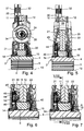
Figuren 4 bis 6 sind verschiedene Schnittansichten vergrößert dargestellt. In der Nähe der Lagereinrichtung 14 ist eine Vordämpfungseinrichtung 44 in die Kupplungsscheibe 1 beziehungsweise die Drehschwingungsdämpfungseinrichtung 2 integriert. Die Vordämpfungseinrichtung 44 umfasst ein Vordämpfungsgehäuse 45, das in axialer Richtung zwischen dem Seitenteil 21 und dem Zwischenteil 11 angeordnet ist. In dem Vordämpfungsgehäuse 45 ist ein Vordämpfungsflansch 46 angeordnet. Der Vordämpfungsflansch 46 ist relativ zu zwei Vordämpfungskäfigen 48, 49 drehbar, die das Vordämpfungsgehäuse 45 bilden. Der Vordämpfungsflansch 46 ist gegen die Wirkung einer Vordämpfungsfedereinrichtung 50 verdrehbar, die in dem Vordämpfungsgehäuse 45 angeordnet ist. - In
Figur 8 ist die Ansicht eines Schnitts entlang der Linie VIII-VIII ausFigur 7 dargestellt, die derFigur 6 entspricht. InFigur 8 sieht man, dass die Zwischennabe 6 eine Außenverzahnung 51 aufweist, die mit einer Innenverzahnung 52 zusammenwirkt, die an dem Zwischenteil 11 vorgesehen ist. An dem Zwischenteil 12 ist eine weitere Innenverzahnung 53 vorgesehen, die ebenfalls mit der Außenverzahnung 51 der Zwischennabe 6 zusammenwirkt. - In
Figur 9 ist ein Ausschnitt ausFigur 8 vergrößert dargestellt. InFigur 9 ist durch einen Doppelpfeil 55 das Verdrehspiel angedeutet, das zwischen der Außenverzahnung 51 der Zwischennabe 6 und der Innenverzahnung 52 des Zwischenteils 11 vorgesehen ist. Das Verdrehspiel 55 ergibt sich aus der Differenz zwischen dem Hauptdämpfungswinkel α2 und dem Vordämpfungswinkel α1. Die Federn 24, 25, 26, 27 inFigur 8 werden auch als Hauptdämpferdruckfedern bezeichnet und dienen dazu, das Moment je nach Drehrichtung auf eines der Zwischenteile 11, 12 zu übertragen. Die Zwischenteile 11, 12 sind durch die Hauptdämpferdruckfedern 24 bis 27 miteinander gekoppelt. - In den
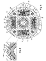
Figuren 10 und 11 ist eine erfindungsgemäße Vordämpfungseinrichtung 104 im Quer- und im Längsschnitt dargestellt. Die Vordämpfungseinrichtung 104 umfasst ein Vordämpfungsgehäuse 105, in dem ein Vordämpfungsflansch 106 angeordnet ist. Der Vordämpfungsflansch 106 ist relativ zu zwei Vordämpfungskäfigen 108, 109 drehbar, die das Vordämpfungsgehäuse 105 bilden. Der Vordämpfungsflansch 106 ist gegen die Wirkung einer Vordämpfungsfedereinrichtung 110 verdrehbar, die in dem Vordämpfungsgehäuse 105 angeordnet ist. - In
Figur 10 sieht man, dass die Vordämpfungsfedereinrichtung 110 vier Vordämpfungsfederelemente 116, 117, 118 und 119 umfasst. Bei Verdrehwinkeln, die kleiner als der Vordämpfungswinkel sind, wird das Moment über die Vordämpfungsfederelemente 116 bis 119, die vorzugsweise als Schraubendruckfedern ausgeführt sind, auf den Vordämpfungsflansch 106 übertragen, der quasi spielfrei drehfest mit der Nabe (4 in denFiguren 3 bis 8 ) verbunden ist. Bei Verdrehwinkeln, die größer als der Vordämpfungswinkel sind, wird das Moment direkt von der Zwischennabe (6 in denFiguren 3 bis 8 ) auf die Nabe übertragen. - Die beiden Vordämpfungskäfige 108, 109 übertragen das Moment auf die Vordämpfungsfederelemente 116 bis 119. Gemäß einem wesentlichen Aspekt der Erfindung sind die Vordämpfungsfederelemente 116 bis 119 an ihren Enden jeweils mit Kunststoffnäpfen 128, 129 bewehrt. Bei den Vordämpfungsfederelementen 116 bis 119 handelt es sich vorzugsweise um Schraubendruckfedern aus Federstahl. Der Vordämpfungsflansch 106 ist vorzugsweise aus Stahl gebildet. Die Kunststoffnäpfe 128, 129 übertragen das Moment auf den Vordämpfungsflansch 106. Alternativ können anstelle der Kunststoffnäpfe 128, 129 auch Kunststoffeinsätze in die Fenster des Vordämpfungsflanschs 106 eingeklipst oder gespritzt werden.
- Radial innen ist der Vordämpfungsflansch 106 mit einer Innenverzahnung 122 ausgestattet. Die Innenverzahnung 122 ist im zusammengebauten Zustand der Kupplungsscheibe umfangsspielfrei, drehfest mit der Nabe (4 in den
Figuren 3 bis 8 ) verbunden. Gemäß einem weiteren wesentlichen Aspekt der Erfindung ist ein ebenfalls verzahntes und vorteilhaft mit etwa konstanter Wandstärke versehenes Kunststoffteil 124 in die Innenverzahnung 122 des Vordämpfungsflanschs 106 eingeklipst oder gespritzt. Das Kunststoffteil 124 dient dazu, einen reibungsarmen Kontakt zu der Nabenverzahnung herzustellen. - In
Figur 12 ist die Vordämpfungseinrichtung 104 aus denFiguren 10 und 11 in Explosionsdarstellung gezeigt. Die vorab beschriebenen Maßnahmen, welche die Bewehrung von Stahlteilen mit Kunststoff betreffen, dienen der Reduzierung des durch Mikrobewegungen hervorgerufenen Kontaktverschleißes zwischen dem Vordämpfungsflansch 106 und seinen Kontaktpartnern. -
1. Kupplungsscheibe 50. Vordämpfungsfedereinrichtung 2. Drehschwingungsdämpfer 51. Außenverzahnung 3. Nabeneinrichtung 52. Innenverzahnung 4. Nabe 53. Innenverzahnung 5. Innenverzahnung 55. Doppelpfeil 6. Zwischennabe 104. Vordämpfungseinrichtung 11. Zwischenteil 105. Vordämpfungsgehäuse 12. Zwischenteil 106. Vordämpfungsflansch 13. Drehachse 108. Vordämpfungskäfig 14. Lagereinrichtung 109. Vordämpfungskäfig 15. Lagereinrichtung 110. Vordämpfungsfedereinrichtung 21. Seitenteil 116. Vordämpfungsfederelement 22. Seitenteil 117. Vordämpfungsfederelement 23. Federeinrichtung 118. Vordämpfungsfederelement 24. Federelement 119. Vordämpfungsfederelement 25. Federelement 122. Innenverzahnung 26. Federelement 124. Kunststoffteil 27. Federelement 128. Kunststoffnapf 28. Abstandsbolzen 129. Kunststoffnapf 30. Belagträgerscheibe 31. Reibbelaghälfte 32. Reibbelaghälfte 34. Schraubendruckfeder 35. Schraubendruckfeder 40. Reibeinrichtung 44. Vordämpfungseinrichtung 45. Vordämpfungsgehäuse 46. Vordämpfungsflansch 48. Vordämpfungskäfig 49. Vordämpfungskäfig
Claims (10)
- Drehschwingungsdämpfer mit einer Hauptdämpfungseinrichtung und einer Vordämpfungseinrichtung (44;104), die bis zu einem Vordämpfungswinkel (α1) wirksam ist und einen Vordämpfungsflansch (46; 106) umfasst, der einerseits an ersten Kopplungsstellen mit Vordämpfungsfederelementen (116-119) und andererseits an zweiten Kopplungsstellen mit einer Nabeneinrichtung (3) gekoppelt ist, dadurch gekennzeichnet, dass die Reibpaarungen der Kontaktpartner an den ersten und/oder zweiten Kopplungsstellen im Hinblick auf Reibung optimiert sind.
- Drehschwingungsdämpfer nach Anspruch 1, dadurch gekennzeichnet, dass jeweils mindestens einer der Kontaktpartner an den ersten und/oder zweiten Kopplungsstellen aus einem reibungsarmen Material, insbesondere aus Kunststoff, gebildet ist.
- Drehschwingungsdämpfer nach Anspruch 2, dadurch gekennzeichnet, dass der Vordämpfungsflansch (46;106) aus Metall, insbesondere aus Stahl, gebildet und an den ersten und/oder zweiten Kopplungsstellen mit Kunststoff bewehrt ist.
- Drehschwingungsdämpfer nach Anspruch 3, dadurch gekennzeichnet, dass der Vordämpfungsflansch (46;106) eine Innenverzahnung (122) aufweist, die in eine Außenverzahnung der Nabeneinrichtung (3,6) eingreift und mit einem Kunststoffteil (124) umgeben ist.
- Drehschwingungsdämpfer nach Anspruch 4, dadurch gekennzeichnet, dass das Kunststoffteil (124) in die Innenverzahnung (122) des Vordämpfungsflanschs (106) eingeklipst ist.
- Drehschwingungsdämpfer nach Anspruch 4, dadurch gekennzeichnet, dass die Innenverzahnung (122) des Vordämpfungsflanschs (106) mit Kunststoff umspritzt ist.
- Drehschwingungsdämpfer nach einem der Ansprüche 2 bis 6, dadurch gekennzeichnet, dass der Vordämpfungsflansch (106) zur Kopplung mit den Vordämpfungsfederelementen (116-119) Fenster aufweist, die an den ersten Kopplungsstellen mit Kunststoff bewehrt sind.
- Drehschwingungsdämpfer nach einem der Ansprüche 2 bis 7, dadurch gekennzeichnet, dass die Vordämpfungsfederelemente (116-119) aus Metall, insbesondere aus Federstahl, gebildet und an den ersten Kopplungsstellen mit Kunststoff bewehrt sind.
- Drehschwingungsdämpfer nach dem vorhergehenden Anspruch, dadurch gekennzeichnet, dass an den Vordämpfungsfederelementen (116-119) Kunststoffnäpfe (128,129) befestigt sind.
- Kupplungsscheibe mit einem Drehschwingungsdämpfer nach einem der vorhergehenden Ansprüche.
Applications Claiming Priority (1)
| Application Number | Priority Date | Filing Date | Title |
|---|---|---|---|
| DE102007013791 | 2007-03-22 |
Publications (3)
| Publication Number | Publication Date |
|---|---|
| EP1972828A2 true EP1972828A2 (de) | 2008-09-24 |
| EP1972828A3 EP1972828A3 (de) | 2010-07-28 |
| EP1972828B1 EP1972828B1 (de) | 2012-08-29 |
Family
ID=39269331
Family Applications (1)
| Application Number | Title | Priority Date | Filing Date |
|---|---|---|---|
| EP20080003332 Active EP1972828B1 (de) | 2007-03-22 | 2008-02-25 | Drehschwingungsdämpfer |
Country Status (3)
| Country | Link |
|---|---|
| EP (1) | EP1972828B1 (de) |
| CN (1) | CN101270793B (de) |
| DE (1) | DE102008010996A1 (de) |
Cited By (3)
| Publication number | Priority date | Publication date | Assignee | Title |
|---|---|---|---|---|
| CN110905972A (zh) * | 2019-11-18 | 2020-03-24 | 华域动力总成部件系统(上海)有限公司 | 集成预减振的飞轮减振器 |
| WO2020228899A1 (de) * | 2019-05-10 | 2020-11-19 | Schaeffler Technologies AG & Co. KG | Drehschwingungsdämpfer mit mehrflanschdämpfer und vordämpfer sowie system und kupplungsscheibe mit drehschwingungsdämpfer |
| CN113557370A (zh) * | 2019-07-01 | 2021-10-26 | 舍弗勒技术股份两合公司 | 离合器从动盘及离合器 |
Families Citing this family (4)
| Publication number | Priority date | Publication date | Assignee | Title |
|---|---|---|---|---|
| CN103975145B (zh) * | 2011-12-05 | 2019-05-10 | 舍弗勒技术股份两合公司 | 传动系 |
| DE102014016569A1 (de) * | 2014-11-08 | 2016-05-12 | Borgwarner Inc. | Drehschwingungstilger |
| DE102016219773B4 (de) * | 2016-10-12 | 2018-09-20 | Schaeffler Technologies AG & Co. KG | Kupplungsscheibe, Reibungskupplungseinrichtung und Antriebsstrang |
| CN114623195A (zh) * | 2020-12-10 | 2022-06-14 | 舍弗勒技术股份两合公司 | 减振装置 |
Family Cites Families (6)
| Publication number | Priority date | Publication date | Assignee | Title |
|---|---|---|---|---|
| JPS5884257A (ja) * | 1981-11-12 | 1983-05-20 | Matsushita Electric Works Ltd | 歯車 |
| FR2652399B1 (fr) * | 1989-09-26 | 1994-06-24 | Valeo | Dispositif amortisseur de torsion a patins de frottement, notamment pour vehicule automobile. |
| US5711407A (en) * | 1994-06-30 | 1998-01-27 | Luk Lamellen Und Kupplungsbau Gmbh | Torsional vibration damper |
| FR2733809B1 (fr) * | 1995-05-02 | 1997-06-13 | Valeo | Amortisseur de torsion a rondelle de commande, notamment friction d'embrayage pour vehicule automobile |
| US6135890A (en) * | 1996-12-11 | 2000-10-24 | Luk Lamellen Und Kupplungsbau Gmbh | Torsional vibration damper |
| FR2797010B1 (fr) * | 1999-07-30 | 2001-11-02 | Valeo | Amortisseur de torsion pour embrayage, en particulier pour vehicule automobile |
-
2008
- 2008-02-25 DE DE102008010996A patent/DE102008010996A1/de not_active Withdrawn
- 2008-02-25 EP EP20080003332 patent/EP1972828B1/de active Active
- 2008-03-21 CN CN2008100882092A patent/CN101270793B/zh not_active Expired - Fee Related
Non-Patent Citations (1)
| Title |
|---|
| None |
Cited By (3)
| Publication number | Priority date | Publication date | Assignee | Title |
|---|---|---|---|---|
| WO2020228899A1 (de) * | 2019-05-10 | 2020-11-19 | Schaeffler Technologies AG & Co. KG | Drehschwingungsdämpfer mit mehrflanschdämpfer und vordämpfer sowie system und kupplungsscheibe mit drehschwingungsdämpfer |
| CN113557370A (zh) * | 2019-07-01 | 2021-10-26 | 舍弗勒技术股份两合公司 | 离合器从动盘及离合器 |
| CN110905972A (zh) * | 2019-11-18 | 2020-03-24 | 华域动力总成部件系统(上海)有限公司 | 集成预减振的飞轮减振器 |
Also Published As
| Publication number | Publication date |
|---|---|
| DE102008010996A1 (de) | 2008-09-25 |
| CN101270793A (zh) | 2008-09-24 |
| EP1972828A3 (de) | 2010-07-28 |
| EP1972828B1 (de) | 2012-08-29 |
| CN101270793B (zh) | 2012-10-10 |
Similar Documents
| Publication | Publication Date | Title |
|---|---|---|
| EP1972828B1 (de) | Drehschwingungsdämpfer | |
| WO2008019641A1 (de) | Drehschwingungsdämpfer | |
| WO2008113316A1 (de) | Drehschwingungsdämpfer | |
| EP2027397B1 (de) | Drehmomentübertragungseinrichtung zum schwingungsreduzierten übertragen von drehmomenten über wenigstens eine welle | |
| DE112008002225B4 (de) | Drehschwingungsdämpfer | |
| EP2228564A1 (de) | Scherenzahnrad mit einem an einem drehmomentübertragenden Hauptzahnrad elastisch abgestützten Hilfszahnrad | |
| DE102009046080A1 (de) | Getriebe-Antriebseinheit | |
| EP2344779A1 (de) | Dämpfereinheit für eine welle | |
| EP1916439B1 (de) | Verfahren zum Herstellen eines Schlingenfederkupplungselements und Torsionsschwingungsdämpfer | |
| EP2505862A1 (de) | Gleichlaufgelenk und Gelenkwelle | |
| DE102017104598A1 (de) | Welle-Nabe-Verbindung mit radial nach außen weisenden Sicherungshaken an einem Federblech und Antriebsstrang | |
| DE10205767A1 (de) | Lamellen-Kupplungseinrichtung mit einer eingangseitigen Dämpfungs- oder/und Federelementanordnung | |
| DE10056342A1 (de) | Torsionsdämpfer für eine Reibungskupplung, insbesondere für Kraftfahrzeuge | |
| DE102010029097B3 (de) | Scherenzahnrad mit einem gegenüber einem drehmomentübertragenden Hauptzahnrad elastisch abgestützten Hilfszahnrad | |
| EP2466163A2 (de) | Lastdrehmomentsperre für eine Getriebe-Antriebseinheit und Aggregat mit einer Lastdrehmomentsperre | |
| DE102006054175A1 (de) | Verbundkupplungswellenaufbau | |
| WO2014114285A2 (de) | Homokinetisches festgelenk mit crashfunktion | |
| DE102012223998A1 (de) | Drehmitnahmeeinrichtung und Reibungskupplung mit dieser | |
| WO2018196960A1 (de) | Wellenverbindung und antriebswelle mit einer solchen wellenverbindung | |
| DE102020107872A1 (de) | Riemenscheibenentkoppler | |
| DE102006059054A1 (de) | Torsionsschwingungsdämpfer mit Endschuhen | |
| DE102010051616A1 (de) | Stirnverzahnte Radlagereinheit mit Innenhärtung | |
| DE102013213747A1 (de) | Schwingungsdämpfer | |
| DE102011003503B4 (de) | Torsionsschwingungsdämpfer, insbesondere für einen hydrodynamischen Drehmomentwandler | |
| DE202017102048U1 (de) | Getriebeeinheit |
Legal Events
| Date | Code | Title | Description |
|---|---|---|---|
| PUAI | Public reference made under article 153(3) epc to a published international application that has entered the european phase |
Free format text: ORIGINAL CODE: 0009012 |
|
| AK | Designated contracting states |
Kind code of ref document: A2 Designated state(s): AT BE BG CH CY CZ DE DK EE ES FI FR GB GR HR HU IE IS IT LI LT LU LV MC MT NL NO PL PT RO SE SI SK TR |
|
| AX | Request for extension of the european patent |
Extension state: AL BA MK RS |
|
| PUAL | Search report despatched |
Free format text: ORIGINAL CODE: 0009013 |
|
| AK | Designated contracting states |
Kind code of ref document: A3 Designated state(s): AT BE BG CH CY CZ DE DK EE ES FI FR GB GR HR HU IE IS IT LI LT LU LV MC MT NL NO PL PT RO SE SI SK TR |
|
| AX | Request for extension of the european patent |
Extension state: AL BA MK RS |
|
| 17P | Request for examination filed |
Effective date: 20110128 |
|
| AKX | Designation fees paid |
Designated state(s): AT BE BG CH CY CZ DE DK EE ES FI FR GB GR HR HU IE IS IT LI LT LU LV MC MT NL NO PL PT RO SE SI SK TR |
|
| RAP1 | Party data changed (applicant data changed or rights of an application transferred) |
Owner name: SCHAEFFLER TECHNOLOGIES GMBH & CO. KG |
|
| 17Q | First examination report despatched |
Effective date: 20110413 |
|
| REG | Reference to a national code |
Ref country code: DE Ref legal event code: R079 Ref document number: 502008008037 Country of ref document: DE Free format text: PREVIOUS MAIN CLASS: F16F0015129000 Ipc: F16F0015123000 |
|
| RAP1 | Party data changed (applicant data changed or rights of an application transferred) |
Owner name: SCHAEFFLER TECHNOLOGIES AG & CO. KG |
|
| RIC1 | Information provided on ipc code assigned before grant |
Ipc: F16F 15/123 20060101AFI20120203BHEP Ipc: F16F 15/139 20060101ALI20120203BHEP Ipc: F16F 15/129 20060101ALI20120203BHEP |
|
| GRAP | Despatch of communication of intention to grant a patent |
Free format text: ORIGINAL CODE: EPIDOSNIGR1 |
|
| GRAS | Grant fee paid |
Free format text: ORIGINAL CODE: EPIDOSNIGR3 |
|
| GRAA | (expected) grant |
Free format text: ORIGINAL CODE: 0009210 |
|
| AK | Designated contracting states |
Kind code of ref document: B1 Designated state(s): AT BE BG CH CY CZ DE DK EE ES FI FR GB GR HR HU IE IS IT LI LT LU LV MC MT NL NO PL PT RO SE SI SK TR |
|
| REG | Reference to a national code |
Ref country code: GB Ref legal event code: FG4D Free format text: NOT ENGLISH |
|
| REG | Reference to a national code |
Ref country code: CH Ref legal event code: EP |
|
| REG | Reference to a national code |
Ref country code: AT Ref legal event code: REF Ref document number: 573243 Country of ref document: AT Kind code of ref document: T Effective date: 20120915 |
|
| REG | Reference to a national code |
Ref country code: IE Ref legal event code: FG4D Free format text: LANGUAGE OF EP DOCUMENT: GERMAN |
|
| REG | Reference to a national code |
Ref country code: DE Ref legal event code: R096 Ref document number: 502008008037 Country of ref document: DE Effective date: 20121025 |
|
| REG | Reference to a national code |
Ref country code: NL Ref legal event code: VDEP Effective date: 20120829 |
|
| REG | Reference to a national code |
Ref country code: LT Ref legal event code: MG4D Effective date: 20120829 |
|
| PG25 | Lapsed in a contracting state [announced via postgrant information from national office to epo] |
Ref country code: IS Free format text: LAPSE BECAUSE OF FAILURE TO SUBMIT A TRANSLATION OF THE DESCRIPTION OR TO PAY THE FEE WITHIN THE PRESCRIBED TIME-LIMIT Effective date: 20121229 Ref country code: HR Free format text: LAPSE BECAUSE OF FAILURE TO SUBMIT A TRANSLATION OF THE DESCRIPTION OR TO PAY THE FEE WITHIN THE PRESCRIBED TIME-LIMIT Effective date: 20120829 Ref country code: FI Free format text: LAPSE BECAUSE OF FAILURE TO SUBMIT A TRANSLATION OF THE DESCRIPTION OR TO PAY THE FEE WITHIN THE PRESCRIBED TIME-LIMIT Effective date: 20120829 Ref country code: NO Free format text: LAPSE BECAUSE OF FAILURE TO SUBMIT A TRANSLATION OF THE DESCRIPTION OR TO PAY THE FEE WITHIN THE PRESCRIBED TIME-LIMIT Effective date: 20121129 Ref country code: LT Free format text: LAPSE BECAUSE OF FAILURE TO SUBMIT A TRANSLATION OF THE DESCRIPTION OR TO PAY THE FEE WITHIN THE PRESCRIBED TIME-LIMIT Effective date: 20120829 Ref country code: CY Free format text: LAPSE BECAUSE OF FAILURE TO SUBMIT A TRANSLATION OF THE DESCRIPTION OR TO PAY THE FEE WITHIN THE PRESCRIBED TIME-LIMIT Effective date: 20120829 |
|
| PG25 | Lapsed in a contracting state [announced via postgrant information from national office to epo] |
Ref country code: SE Free format text: LAPSE BECAUSE OF FAILURE TO SUBMIT A TRANSLATION OF THE DESCRIPTION OR TO PAY THE FEE WITHIN THE PRESCRIBED TIME-LIMIT Effective date: 20120829 Ref country code: SI Free format text: LAPSE BECAUSE OF FAILURE TO SUBMIT A TRANSLATION OF THE DESCRIPTION OR TO PAY THE FEE WITHIN THE PRESCRIBED TIME-LIMIT Effective date: 20120829 Ref country code: LV Free format text: LAPSE BECAUSE OF FAILURE TO SUBMIT A TRANSLATION OF THE DESCRIPTION OR TO PAY THE FEE WITHIN THE PRESCRIBED TIME-LIMIT Effective date: 20120829 Ref country code: GR Free format text: LAPSE BECAUSE OF FAILURE TO SUBMIT A TRANSLATION OF THE DESCRIPTION OR TO PAY THE FEE WITHIN THE PRESCRIBED TIME-LIMIT Effective date: 20121130 Ref country code: PT Free format text: LAPSE BECAUSE OF FAILURE TO SUBMIT A TRANSLATION OF THE DESCRIPTION OR TO PAY THE FEE WITHIN THE PRESCRIBED TIME-LIMIT Effective date: 20121231 |
|
| PG25 | Lapsed in a contracting state [announced via postgrant information from national office to epo] |
Ref country code: CZ Free format text: LAPSE BECAUSE OF FAILURE TO SUBMIT A TRANSLATION OF THE DESCRIPTION OR TO PAY THE FEE WITHIN THE PRESCRIBED TIME-LIMIT Effective date: 20120829 Ref country code: RO Free format text: LAPSE BECAUSE OF FAILURE TO SUBMIT A TRANSLATION OF THE DESCRIPTION OR TO PAY THE FEE WITHIN THE PRESCRIBED TIME-LIMIT Effective date: 20120829 Ref country code: DK Free format text: LAPSE BECAUSE OF FAILURE TO SUBMIT A TRANSLATION OF THE DESCRIPTION OR TO PAY THE FEE WITHIN THE PRESCRIBED TIME-LIMIT Effective date: 20120829 Ref country code: EE Free format text: LAPSE BECAUSE OF FAILURE TO SUBMIT A TRANSLATION OF THE DESCRIPTION OR TO PAY THE FEE WITHIN THE PRESCRIBED TIME-LIMIT Effective date: 20120829 Ref country code: ES Free format text: LAPSE BECAUSE OF FAILURE TO SUBMIT A TRANSLATION OF THE DESCRIPTION OR TO PAY THE FEE WITHIN THE PRESCRIBED TIME-LIMIT Effective date: 20121210 Ref country code: NL Free format text: LAPSE BECAUSE OF FAILURE TO SUBMIT A TRANSLATION OF THE DESCRIPTION OR TO PAY THE FEE WITHIN THE PRESCRIBED TIME-LIMIT Effective date: 20120829 |
|
| PG25 | Lapsed in a contracting state [announced via postgrant information from national office to epo] |
Ref country code: SK Free format text: LAPSE BECAUSE OF FAILURE TO SUBMIT A TRANSLATION OF THE DESCRIPTION OR TO PAY THE FEE WITHIN THE PRESCRIBED TIME-LIMIT Effective date: 20120829 Ref country code: PL Free format text: LAPSE BECAUSE OF FAILURE TO SUBMIT A TRANSLATION OF THE DESCRIPTION OR TO PAY THE FEE WITHIN THE PRESCRIBED TIME-LIMIT Effective date: 20120829 Ref country code: IT Free format text: LAPSE BECAUSE OF FAILURE TO SUBMIT A TRANSLATION OF THE DESCRIPTION OR TO PAY THE FEE WITHIN THE PRESCRIBED TIME-LIMIT Effective date: 20120829 |
|
| PLBE | No opposition filed within time limit |
Free format text: ORIGINAL CODE: 0009261 |
|
| STAA | Information on the status of an ep patent application or granted ep patent |
Free format text: STATUS: NO OPPOSITION FILED WITHIN TIME LIMIT |
|
| PG25 | Lapsed in a contracting state [announced via postgrant information from national office to epo] |
Ref country code: BG Free format text: LAPSE BECAUSE OF FAILURE TO SUBMIT A TRANSLATION OF THE DESCRIPTION OR TO PAY THE FEE WITHIN THE PRESCRIBED TIME-LIMIT Effective date: 20121129 |
|
| 26N | No opposition filed |
Effective date: 20130530 |
|
| BERE | Be: lapsed |
Owner name: SCHAEFFLER TECHNOLOGIES A.G. & CO. KG Effective date: 20130228 |
|
| REG | Reference to a national code |
Ref country code: DE Ref legal event code: R097 Ref document number: 502008008037 Country of ref document: DE Effective date: 20130530 |
|
| PG25 | Lapsed in a contracting state [announced via postgrant information from national office to epo] |
Ref country code: MC Free format text: LAPSE BECAUSE OF NON-PAYMENT OF DUE FEES Effective date: 20130228 |
|
| REG | Reference to a national code |
Ref country code: CH Ref legal event code: PL |
|
| GBPC | Gb: european patent ceased through non-payment of renewal fee |
Effective date: 20130225 |
|
| PG25 | Lapsed in a contracting state [announced via postgrant information from national office to epo] |
Ref country code: CH Free format text: LAPSE BECAUSE OF NON-PAYMENT OF DUE FEES Effective date: 20130228 Ref country code: LI Free format text: LAPSE BECAUSE OF NON-PAYMENT OF DUE FEES Effective date: 20130228 |
|
| REG | Reference to a national code |
Ref country code: IE Ref legal event code: MM4A |
|
| PG25 | Lapsed in a contracting state [announced via postgrant information from national office to epo] |
Ref country code: GB Free format text: LAPSE BECAUSE OF NON-PAYMENT OF DUE FEES Effective date: 20130225 Ref country code: BE Free format text: LAPSE BECAUSE OF NON-PAYMENT OF DUE FEES Effective date: 20130228 Ref country code: IE Free format text: LAPSE BECAUSE OF NON-PAYMENT OF DUE FEES Effective date: 20130225 |
|
| REG | Reference to a national code |
Ref country code: DE Ref legal event code: R081 Ref document number: 502008008037 Country of ref document: DE Owner name: SCHAEFFLER TECHNOLOGIES AG & CO. KG, DE Free format text: FORMER OWNER: SCHAEFFLER TECHNOLOGIES AG & CO. KG, 91074 HERZOGENAURACH, DE Effective date: 20140213 Ref country code: DE Ref legal event code: R081 Ref document number: 502008008037 Country of ref document: DE Owner name: SCHAEFFLER TECHNOLOGIES GMBH & CO. KG, DE Free format text: FORMER OWNER: SCHAEFFLER TECHNOLOGIES AG & CO. KG, 91074 HERZOGENAURACH, DE Effective date: 20140213 |
|
| REG | Reference to a national code |
Ref country code: AT Ref legal event code: MM01 Ref document number: 573243 Country of ref document: AT Kind code of ref document: T Effective date: 20130225 |
|
| PG25 | Lapsed in a contracting state [announced via postgrant information from national office to epo] |
Ref country code: AT Free format text: LAPSE BECAUSE OF NON-PAYMENT OF DUE FEES Effective date: 20130225 |
|
| PGFP | Annual fee paid to national office [announced via postgrant information from national office to epo] |
Ref country code: FR Payment date: 20140226 Year of fee payment: 7 |
|
| PG25 | Lapsed in a contracting state [announced via postgrant information from national office to epo] |
Ref country code: MT Free format text: LAPSE BECAUSE OF FAILURE TO SUBMIT A TRANSLATION OF THE DESCRIPTION OR TO PAY THE FEE WITHIN THE PRESCRIBED TIME-LIMIT Effective date: 20120829 |
|
| REG | Reference to a national code |
Ref country code: DE Ref legal event code: R081 Ref document number: 502008008037 Country of ref document: DE Owner name: SCHAEFFLER TECHNOLOGIES AG & CO. KG, DE Free format text: FORMER OWNER: SCHAEFFLER TECHNOLOGIES GMBH & CO. KG, 91074 HERZOGENAURACH, DE Effective date: 20150223 |
|
| PG25 | Lapsed in a contracting state [announced via postgrant information from national office to epo] |
Ref country code: TR Free format text: LAPSE BECAUSE OF FAILURE TO SUBMIT A TRANSLATION OF THE DESCRIPTION OR TO PAY THE FEE WITHIN THE PRESCRIBED TIME-LIMIT Effective date: 20120829 |
|
| PG25 | Lapsed in a contracting state [announced via postgrant information from national office to epo] |
Ref country code: LU Free format text: LAPSE BECAUSE OF NON-PAYMENT OF DUE FEES Effective date: 20130225 Ref country code: HU Free format text: LAPSE BECAUSE OF FAILURE TO SUBMIT A TRANSLATION OF THE DESCRIPTION OR TO PAY THE FEE WITHIN THE PRESCRIBED TIME-LIMIT; INVALID AB INITIO Effective date: 20080225 |
|
| REG | Reference to a national code |
Ref country code: FR Ref legal event code: ST Effective date: 20151030 |
|
| PG25 | Lapsed in a contracting state [announced via postgrant information from national office to epo] |
Ref country code: FR Free format text: LAPSE BECAUSE OF NON-PAYMENT OF DUE FEES Effective date: 20150302 |
|
| P01 | Opt-out of the competence of the unified patent court (upc) registered |
Effective date: 20230523 |
|
| PGFP | Annual fee paid to national office [announced via postgrant information from national office to epo] |
Ref country code: DE Payment date: 20260228 Year of fee payment: 19 |