EP1972785A1 - Check valve for a vacuum pump - Google Patents
Check valve for a vacuum pump Download PDFInfo
- Publication number
- EP1972785A1 EP1972785A1 EP08200004A EP08200004A EP1972785A1 EP 1972785 A1 EP1972785 A1 EP 1972785A1 EP 08200004 A EP08200004 A EP 08200004A EP 08200004 A EP08200004 A EP 08200004A EP 1972785 A1 EP1972785 A1 EP 1972785A1
- Authority
- EP
- European Patent Office
- Prior art keywords
- valve
- valve member
- check valve
- vacuum pump
- axis
- Prior art date
- Legal status (The legal status is an assumption and is not a legal conclusion. Google has not performed a legal analysis and makes no representation as to the accuracy of the status listed.)
- Granted
Links
- 238000005086 pumping Methods 0.000 claims description 18
- 238000005461 lubrication Methods 0.000 claims description 5
- 238000004891 communication Methods 0.000 claims description 3
- 239000012530 fluid Substances 0.000 claims description 3
- 238000002485 combustion reaction Methods 0.000 claims description 2
- 230000001419 dependent effect Effects 0.000 claims 1
- 101000793686 Homo sapiens Azurocidin Proteins 0.000 description 3
- 230000005484 gravity Effects 0.000 description 2
- 230000005012 migration Effects 0.000 description 2
- 238000013508 migration Methods 0.000 description 2
- 238000007789 sealing Methods 0.000 description 2
- 230000006835 compression Effects 0.000 description 1
- 238000007906 compression Methods 0.000 description 1
- 239000000446 fuel Substances 0.000 description 1
- 239000003595 mist Substances 0.000 description 1
- 238000012986 modification Methods 0.000 description 1
- 230000004048 modification Effects 0.000 description 1
Images


Classifications
-
- F—MECHANICAL ENGINEERING; LIGHTING; HEATING; WEAPONS; BLASTING
- F04—POSITIVE - DISPLACEMENT MACHINES FOR LIQUIDS; PUMPS FOR LIQUIDS OR ELASTIC FLUIDS
- F04C—ROTARY-PISTON, OR OSCILLATING-PISTON, POSITIVE-DISPLACEMENT MACHINES FOR LIQUIDS; ROTARY-PISTON, OR OSCILLATING-PISTON, POSITIVE-DISPLACEMENT PUMPS
- F04C18/00—Rotary-piston pumps specially adapted for elastic fluids
- F04C18/30—Rotary-piston pumps specially adapted for elastic fluids having the characteristics covered by two or more of groups F04C18/02, F04C18/08, F04C18/22, F04C18/24, F04C18/48, or having the characteristics covered by one of these groups together with some other type of movement between co-operating members
- F04C18/34—Rotary-piston pumps specially adapted for elastic fluids having the characteristics covered by two or more of groups F04C18/02, F04C18/08, F04C18/22, F04C18/24, F04C18/48, or having the characteristics covered by one of these groups together with some other type of movement between co-operating members having the movement defined in group F04C18/08 or F04C18/22 and relative reciprocation between the co-operating members
- F04C18/344—Rotary-piston pumps specially adapted for elastic fluids having the characteristics covered by two or more of groups F04C18/02, F04C18/08, F04C18/22, F04C18/24, F04C18/48, or having the characteristics covered by one of these groups together with some other type of movement between co-operating members having the movement defined in group F04C18/08 or F04C18/22 and relative reciprocation between the co-operating members with vanes reciprocating with respect to the inner member
- F04C18/3441—Rotary-piston pumps specially adapted for elastic fluids having the characteristics covered by two or more of groups F04C18/02, F04C18/08, F04C18/22, F04C18/24, F04C18/48, or having the characteristics covered by one of these groups together with some other type of movement between co-operating members having the movement defined in group F04C18/08 or F04C18/22 and relative reciprocation between the co-operating members with vanes reciprocating with respect to the inner member the inner and outer member being in contact along one line or continuous surface substantially parallel to the axis of rotation
- F04C18/3442—Rotary-piston pumps specially adapted for elastic fluids having the characteristics covered by two or more of groups F04C18/02, F04C18/08, F04C18/22, F04C18/24, F04C18/48, or having the characteristics covered by one of these groups together with some other type of movement between co-operating members having the movement defined in group F04C18/08 or F04C18/22 and relative reciprocation between the co-operating members with vanes reciprocating with respect to the inner member the inner and outer member being in contact along one line or continuous surface substantially parallel to the axis of rotation the surfaces of the inner and outer member, forming the inlet and outlet opening
-
- F—MECHANICAL ENGINEERING; LIGHTING; HEATING; WEAPONS; BLASTING
- F16—ENGINEERING ELEMENTS AND UNITS; GENERAL MEASURES FOR PRODUCING AND MAINTAINING EFFECTIVE FUNCTIONING OF MACHINES OR INSTALLATIONS; THERMAL INSULATION IN GENERAL
- F16K—VALVES; TAPS; COCKS; ACTUATING-FLOATS; DEVICES FOR VENTING OR AERATING
- F16K15/00—Check valves
- F16K15/02—Check valves with guided rigid valve members
- F16K15/025—Check valves with guided rigid valve members the valve being loaded by a spring
-
- F—MECHANICAL ENGINEERING; LIGHTING; HEATING; WEAPONS; BLASTING
- F04—POSITIVE - DISPLACEMENT MACHINES FOR LIQUIDS; PUMPS FOR LIQUIDS OR ELASTIC FLUIDS
- F04C—ROTARY-PISTON, OR OSCILLATING-PISTON, POSITIVE-DISPLACEMENT MACHINES FOR LIQUIDS; ROTARY-PISTON, OR OSCILLATING-PISTON, POSITIVE-DISPLACEMENT PUMPS
- F04C2220/00—Application
- F04C2220/10—Vacuum
-
- F—MECHANICAL ENGINEERING; LIGHTING; HEATING; WEAPONS; BLASTING
- F04—POSITIVE - DISPLACEMENT MACHINES FOR LIQUIDS; PUMPS FOR LIQUIDS OR ELASTIC FLUIDS
- F04C—ROTARY-PISTON, OR OSCILLATING-PISTON, POSITIVE-DISPLACEMENT MACHINES FOR LIQUIDS; ROTARY-PISTON, OR OSCILLATING-PISTON, POSITIVE-DISPLACEMENT PUMPS
- F04C2240/00—Components
- F04C2240/60—Shafts
-
- F—MECHANICAL ENGINEERING; LIGHTING; HEATING; WEAPONS; BLASTING
- F04—POSITIVE - DISPLACEMENT MACHINES FOR LIQUIDS; PUMPS FOR LIQUIDS OR ELASTIC FLUIDS
- F04C—ROTARY-PISTON, OR OSCILLATING-PISTON, POSITIVE-DISPLACEMENT MACHINES FOR LIQUIDS; ROTARY-PISTON, OR OSCILLATING-PISTON, POSITIVE-DISPLACEMENT PUMPS
- F04C2270/00—Control; Monitoring or safety arrangements
- F04C2270/70—Safety, emergency conditions or requirements
- F04C2270/701—Cold start
Definitions
- the present invention relates to vacuum pumps having forced oil lubrication principally for automotive vehicle applications and in particular to a check valve for such a vacuum pump.
- Vehicles often comprise components that are vacuum operated, an important example being servo-assisted brakes.
- a partial vacuum is present in the part of the intake manifold downstream of the main throttle and no special steps need to be taken to provide a vacuum source.
- manifold vacuum cannot be relied upon as a vacuum source.
- any variant of a vehicle fitted with a diesel engine there is no manifold vacuum, because diesel engines operate with wide open throttle and load is varied not by throttling the air intake but by metering the quantity of fuel directly or indirectly injected into the cylinders.
- electrically driven vehicles and vehicles with hybrid drive systems may not always have a vacuum source available at all times.
- vacuum pumps for use in automotive vehicles have been proposed previously and these fall into two categories, namely engine driven pumps and electrically driven pumps.
- the check valve has a housing 2 supported by a shaft 3 connected to a rotor of a sliding vane vacuum pump.
- a positive oil supply passage 4 communicates with a valve chamber 6 defined by the housing 2 when a valve member in the form of a check valve ball 7 is moved away from its seat.
- a spring 8 located in a spring housing 9 is used to bias the check valve ball 7 against a seat as shown in Fig.6 .
- An oil inlet passage 5 is also in fluid communication with the valve chamber 6.
- the oil inlet passage 5 supplies oil to interior components of the vacuum pump and so, when the pump is operating, is maintained at a pressure of approximately minus 1 bar (relative to atmospheric pressure).
- the check valve ball is subject to the positive pressure P1 of the oil feed in the oil supply passage 4 to one side and the minus 1 bar pressure P2 (vacuum) in the inlet supply passage 5 to the other side.
- This differential pressure is sufficient to move the valve check ball 7 away from its seat so as to permit oil to flow to the interior of the vacuum pump.
- the arrangement of the check valve is such that a pressure differential of 1 bar is sufficient to lift the valve check ball 7 from its seat so that as soon as the vacuum pump starts to operate oil can be drawn in through the inlet passage 5 even if the pressure in the oil supply passage is at or close to atmospheric pressure.
- the spring may react between an end cap fastened to the valve housing and the valve member.
- the oil supply may be connected to the valve chamber by an oil supply passage and, when the valve member is in the closed position, the valve chamber may remain in fluid communication with the oil supply passage.
- a second end cap may be fastened to the valve housing to provide an end stop for the valve member thereby determining the closed position of the valve member.
- a vacuum pump for a motor vehicle driven by an oil lubricated internal combustion engine comprising a rotary pumping element, a drive means for driving the rotary pumping element, an oil supply from the engine for interior lubrication of the vacuum pump and a check valve constructed in accordance with said first aspect of the invention.
- the rotary pumping element may comprise a rotor and at least one sliding vane.
- the drive means may comprises one of a chain drive from the engine of the motor vehicle, a belt drive from the engine of the motor vehicle, a hydraulic motor, a pneumatic motor and an electric motor.
- a single vane vacuum pump 1 having a rotary pumping element comprising a rotor 10 mounted eccentrically within a housing 12 having an inner surface defining a pump chamber 16 and a single flat vane 14 slideably mounted diametrically with a close running clearance within the rotor 10.
- the shape of the pump chamber 16 is such that the opposite ends of the vane 14 make sealing contact with the surface of the pump chamber 16 in all angular positions of the rotor 10. It will be appreciated that the vacuum pump could have several vanes supported by the rotor.
- the outer surface of the rotor 10 makes sealing contact with the surface of the pump chamber 16 at the six o'clock position as shown in Fig. 1 .
- the vacuum pump 1 also has an air inlet passage 18 containing an anti-oil migration valve which, for a pump in which the rotor 10 is driven counterclockwise (as represented by the arrow in Figure 1 ), communicates with the variable volume working chamber defined to the right of the rotor 10.
- the vacuum pump 1 also has an exhaust port 20a that communicates with the working chamber to the left of the rotor as viewed and with an outlet or exhaust conduit 20 (shown in Figure 2 ).
- a non-return valve 22 (shown in Figure 2 ) is arranged in the exhaust passage 20 such that air and oil can flow out of the pump chamber 16 but cannot flow in the opposite direction.
- the air may be drawn from a brake servo of the motor vehicle and the air and oil flowing through the exhaust conduit may be returned to a sump of an engine fitted to the motor vehicle and oil is supplied to the vacuum pump 1 from a lubrication circuit of the engine.
- the vacuum pump 1 is connected to the lubrication circuit of the engine by means of a low pressure oil supply pipe 28.
- the oil from the engine passes through a check valve 50 and ultimately flows to the vacuum side of the rotor 10 where the oil is atomised into a fine mist carried by the pumped air to lubricate the moving parts of the pump 1.
- the check valve 50 is located in a support shaft 27 which forms a check valve housing and rotates with the rotor 10 about a common axis of rotation X-X.
- the support shaft 27 is rotatably supported by the pump housing 12 by one or more bearings (not shown).
- the rotatable connector 31 is rotatably connected to the oil supply passage 34 by a snap connector 33 and is sealed by a seal 32.
- the valve member 40 has an end face 42 from which extends a cylindrical projection 43 and a tubular body portion 41.
- a spring 46 is located within the tubular body portion 41 and reacts between the valve member 40 and a first end cap 38 threadingly fastened to the shaft 27 to close off one end of the valve chamber 36.
- the end cap 38 has a through vent passage 39 formed therein to ensure that the interior of the tubular body portion 41 always remains at atmospheric pressure.
- a second end cap 37 is threadingly fastened to the shaft 27 to close off the opposite end of the valve chamber 36 to the end closed by the first end cap 38.
- the second end cap 37 has a projection 44 formed therein on for co-operation with the cylindrical projection 43 on the valve member 40 so as to define an end stop defining the closed position of the valve member 40.
- the valve member 40 is slideable along a slide axis Y-Y which is in this case arranged to be at a right angle with respect to the axis of rotation X-X so as to maximise the centrifugal force applied to the valve member 40 when the shaft 27 rotates with the rotor 10.
- the slide axis Y-Y could be arranged at a different angle to the axis of rotation such as for example 45 degrees but it is preferred to arrange the slide axis at 90 degrees as this maximises the centrifugal force produced when the shaft 27 rotates.
- the force produced by the spring 46 can therefore hold the valve member 40 firmly in its closed position against the end stop in the form of the projection 44 on the second end cap 37.
- valve member 40 is then subject to both oil pressure acting on its end face 42 and to centrifugal force due to its rotation about the axis of rotation X-X.
- a force balance then exists in which if the combined force produced by the pressure on the end face and the centrifugal force exceed the force produced by the spring then the valve member 40 will move away from the end stop 44.
- the centrifugal force F on the valve member is equal to (sin ⁇ )mr ⁇ 2 .
- ⁇ is the angle between the slide axis Y-Y and the axis of rotation X-X (sin ⁇ is equal to 1.0 when this angle is 90 degrees)
- m is the mass of the valve member
- r is the distance of the centre of gravity C of the valve member 40 from the axis of rotation X-X
- w is the rotational speed of the shaft 27.
- the force Fp2 produced by oil pressure will be equal to the total area of the end face 42 multiplied by the pressure P1 in the supply passage and, when the inlet passage 35 is uncovered, the force Fp3 will be equal to the total area of the end face 42 multiplied by the pressure in the valve chamber 36 which will be a pressure lower than the pressure P1 in the supply passage 34 but higher than the pressure P2 in the inlet passage 35.
- the supply passage 34 can be arranged to be closed when the valve member 40 moves to its closed position. This can be achieved by making the supply passage 34 the same size as the inlet passage 35 or by realigning the supply passage 34. In this case, the moving of the valve member 40 away from its closed position is achieved solely by the application of centrifugal force until the supply passage 34 is uncovered.
- a low pressure oil supply pipe 28 from an engine is connected to the check valve 50 and the check valve member 50 prevents the backflow of oil from the vacuum pump, an air inlet 18 containing an anti-oil migration valve is provided and an outlet conduit 20 having a non-return valve 22 is arranged such that air and oil can flow out of the vacuum pump but cannot flow in the opposite direction.
- a further difference between this embodiment and that shown in Figs.1 and 2 is that the vacuum pump is independently driven by an electric motor 124. It will however be appreciated that the electric motor 124 could be replaced by a hydraulic motor or a pneumatic motor.
- an electric motor is that it is able to provide a high vacuum even when the engine of the motor vehicle is operating slowly.
- valve housing does not rotate with the rotor 10 but remains stationary.
- the check valve has a valve member slideably supported in a valve chamber and moved by a spring to a closed position.
- the valve member is moved against the action of the spring by the oil supply pressure acting upon an end face of the valve member in order to open the oil inlet passage to the vacuum pump.
- the valve member is arranged to be unaffected by the pressure in an oil inlet passage connected to the vacuum pump by arranging for a side of the valve member to close off the oil inlet passage.
- valve member In this way the pressure in the oil inlet passage cannot act on the end face of the valve member to affect its position until the valve member has uncovered the oil inlet passage.
- the valve member is moved to an open position solely by the action of the pressure in the valve chamber acting on the end face of the valve member.
Landscapes
- Engineering & Computer Science (AREA)
- General Engineering & Computer Science (AREA)
- Mechanical Engineering (AREA)
- Applications Or Details Of Rotary Compressors (AREA)
Abstract
Description
- The present invention relates to vacuum pumps having forced oil lubrication principally for automotive vehicle applications and in particular to a check valve for such a vacuum pump.
- Vehicles often comprise components that are vacuum operated, an important example being servo-assisted brakes. In a vehicle having a conventional spark-ignition engine, a partial vacuum is present in the part of the intake manifold downstream of the main throttle and no special steps need to be taken to provide a vacuum source. There are however several cases when manifold vacuum cannot be relied upon as a vacuum source. For example, in any variant of a vehicle fitted with a diesel engine there is no manifold vacuum, because diesel engines operate with wide open throttle and load is varied not by throttling the air intake but by metering the quantity of fuel directly or indirectly injected into the cylinders. Likewise electrically driven vehicles and vehicles with hybrid drive systems may not always have a vacuum source available at all times.
- For these reasons, vacuum pumps for use in automotive vehicles have been proposed previously and these fall into two categories, namely engine driven pumps and electrically driven pumps.
- It is known to provide an oil check valve to prevent the backflow of oil from the vacuum pump to the oil supply from the engine. Such a check valve is shown in
Fig.6 of the accompanying drawing. - The check valve has a housing 2 supported by a shaft 3 connected to a rotor of a sliding vane vacuum pump. A positive oil supply passage 4 communicates with a valve chamber 6 defined by the housing 2 when a valve member in the form of a check valve ball 7 is moved away from its seat. A spring 8 located in a spring housing 9 is used to bias the check valve ball 7 against a seat as shown in
Fig.6 . Anoil inlet passage 5 is also in fluid communication with the valve chamber 6. - The
oil inlet passage 5 supplies oil to interior components of the vacuum pump and so, when the pump is operating, is maintained at a pressure of approximately minus 1 bar (relative to atmospheric pressure). - Therefore during normal running of the vacuum pump the check valve ball is subject to the positive pressure P1 of the oil feed in the oil supply passage 4 to one side and the minus 1 bar pressure P2 (vacuum) in the
inlet supply passage 5 to the other side. This differential pressure is sufficient to move the valve check ball 7 away from its seat so as to permit oil to flow to the interior of the vacuum pump. The arrangement of the check valve is such that a pressure differential of 1 bar is sufficient to lift the valve check ball 7 from its seat so that as soon as the vacuum pump starts to operate oil can be drawn in through theinlet passage 5 even if the pressure in the oil supply passage is at or close to atmospheric pressure. - It is a problem with this arrangement that even after the pump is stopped, the pressure in the
oil inlet passage 5 can remain at minus 1 bar for a very long time. Therefore, even if the oil feed pressure P1 in the oil supply passage 4 has dropped to zero, the check valve ball 7 could still be in a partially open position for some time due to the minus 1 bar pressure (vacuum) in theinlet passage 5. The consequence of this is that oil can be drawn into the vacuum pump for a long period of time causing hydraulic lock within the vacuum pump. The next time the vacuum pump is started damage to the vacuum pump will often occur. - It is an object of this invention to provide an improved check valve for a vacuum pump.
- According to a first aspect of the invention there is provided a check valve for a vacuum pump having a rotary pumping element connected to an oil supply, the check valve is rotatable with the rotary pumping element and has a valve member moved against the action of a spring by centrifugal force when the rotary pumping element rotates so as to selectively open an oil inlet passage to the vacuum pump, characterized in that the valve member has an end face and is moved against the action of the spring by a combination of centrifugal force and the oil supply pressure acting upon the end face of the valve member.
- The rotary pumping element may be rotatable about an axis of rotation and the check valve may further comprise a valve housing rotatable about the axis of rotation, the valve member is slidingly supported in a valve chamber formed by the valve housing so as to be slideable along a slide axis, the spring biases the valve member into a closed position where it closes off the oil inlet passage to the vacuum pump and the slide axis of the check valve is inclined relative to the axis of rotation of the rotary pumping element.
- Preferably, the slide axis may be arranged at a right angle with respect to the axis of rotation so as to maximise the centrifugal force on the valve member.
- The spring may react between an end cap fastened to the valve housing and the valve member.
- The valve member may have an end face and a tubular body portion extending away from the end face and the spring may be located within the tubular body portion of the valve member.
- The end cap may have a vent passage formed therein so that the interior of the tubular body portion of the valve member is maintained at atmospheric pressure.
- The oil supply may be connected to the valve chamber by an oil supply passage and, when the valve member is in the closed position, the valve chamber may remain in fluid communication with the oil supply passage.
- A second end cap may be fastened to the valve housing to provide an end stop for the valve member thereby determining the closed position of the valve member.
- According to a second aspect of the invention there is provided a vacuum pump for a motor vehicle driven by an oil lubricated internal combustion engine, the vacuum pump comprising a rotary pumping element, a drive means for driving the rotary pumping element, an oil supply from the engine for interior lubrication of the vacuum pump and a check valve constructed in accordance with said first aspect of the invention.
- The rotary pumping element may comprise a rotor and at least one sliding vane.
- The drive means may comprises one of a chain drive from the engine of the motor vehicle, a belt drive from the engine of the motor vehicle, a hydraulic motor, a pneumatic motor and an electric motor.
- The invention will now be described by way of example with reference to the accompanying drawing of which:-
-
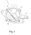
Fig.1 is a transverse section through a sliding vane vacuum pump according to the invention; -
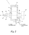
Fig.2 is a longitudinal section through the pump shown inFig.1 showing in dotted outline the location of a check valve according to the invention; -
Fig.3 is a cross-section through the check valve shown inFig.2 showing a valve member in an open position; -
Fig.4 is an enlarged cross-section similar toFig.3 , showing the valve member in a closed position; -
Fig.5 is a longitudinal cross-section similar toFig.2 showing an alternative type of vacuum pump and the location of a check valve according to the invention when used with such a pump; and -
Fig.6 is a cross-section through a prior art check valve. - Referring firstly to
Figure 1 there is shown a single vane vacuum pump 1 having a rotary pumping element comprising arotor 10 mounted eccentrically within ahousing 12 having an inner surface defining apump chamber 16 and a singleflat vane 14 slideably mounted diametrically with a close running clearance within therotor 10. The shape of thepump chamber 16 is such that the opposite ends of thevane 14 make sealing contact with the surface of thepump chamber 16 in all angular positions of therotor 10. It will be appreciated that the vacuum pump could have several vanes supported by the rotor. The outer surface of therotor 10 makes sealing contact with the surface of thepump chamber 16 at the six o'clock position as shown inFig. 1 . - The vacuum pump 1 also has an
air inlet passage 18 containing an anti-oil migration valve which, for a pump in which therotor 10 is driven counterclockwise (as represented by the arrow inFigure 1 ), communicates with the variable volume working chamber defined to the right of therotor 10. - The vacuum pump 1 also has an
exhaust port 20a that communicates with the working chamber to the left of the rotor as viewed and with an outlet or exhaust conduit 20 (shown inFigure 2 ). A non-return valve 22 (shown inFigure 2 ) is arranged in theexhaust passage 20 such that air and oil can flow out of thepump chamber 16 but cannot flow in the opposite direction. - In operation, as the
rotor 10 turns counter clockwise, the volume of the working chamber to the right of therotor 10 is bounded by therotor 10, the surface of thepump chamber 16 and thevane 14 increases and draws air in from the suction port. In the other working chamber, the same air is compressed and forced out of theexhaust port 20a past thenon-return valve 22 into theexhaust conduit 20. - In the application of such a vacuum pump to an automotive vehicle having an oil lubricated engine, the air may be drawn from a brake servo of the motor vehicle and the air and oil flowing through the exhaust conduit may be returned to a sump of an engine fitted to the motor vehicle and oil is supplied to the vacuum pump 1 from a lubrication circuit of the engine.
- Although a rotary vane pumping element is shown and described it will be appreciated that the invention can be applied to alternative designs of pump.
- As shown in
Figure 2 , the pump 1 is driven by a drive member in the form of apulley 24 which is driven by a belt or chain from the engine of the motor vehicle. Thepulley 24 is driveably connected to therotor 10 by adrive shaft 26 supported by bearings (not shown) located in thehousing 12. - The vacuum pump 1 is connected to the lubrication circuit of the engine by means of a low pressure
oil supply pipe 28. The oil from the engine passes through acheck valve 50 and ultimately flows to the vacuum side of therotor 10 where the oil is atomised into a fine mist carried by the pumped air to lubricate the moving parts of the pump 1. - The
check valve 50 is located in asupport shaft 27 which forms a check valve housing and rotates with therotor 10 about a common axis of rotation X-X. Thesupport shaft 27 is rotatably supported by thepump housing 12 by one or more bearings (not shown). - As shown in
Figure 3 , theshaft 27 forming the check valve housing defines anoil supply passage 34 connected via arotatable connector 31 to the low pressureoil supply pipe 28, anoil inlet passage 35 connected to the interior of the vacuum pump 1 and avalve chamber 36 in which is slidingly supported avalve member 40. - The
rotatable connector 31 is rotatably connected to theoil supply passage 34 by asnap connector 33 and is sealed by aseal 32. - The
valve member 40 has anend face 42 from which extends acylindrical projection 43 and atubular body portion 41. Aspring 46 is located within thetubular body portion 41 and reacts between thevalve member 40 and afirst end cap 38 threadingly fastened to theshaft 27 to close off one end of thevalve chamber 36. Theend cap 38 has a throughvent passage 39 formed therein to ensure that the interior of thetubular body portion 41 always remains at atmospheric pressure. - A
second end cap 37 is threadingly fastened to theshaft 27 to close off the opposite end of thevalve chamber 36 to the end closed by thefirst end cap 38. Thesecond end cap 37 has aprojection 44 formed therein on for co-operation with thecylindrical projection 43 on thevalve member 40 so as to define an end stop defining the closed position of thevalve member 40. - The
valve member 40 is slideable along a slide axis Y-Y which is in this case arranged to be at a right angle with respect to the axis of rotation X-X so as to maximise the centrifugal force applied to thevalve member 40 when theshaft 27 rotates with therotor 10. It will be appreciated that the slide axis Y-Y could be arranged at a different angle to the axis of rotation such as for example 45 degrees but it is preferred to arrange the slide axis at 90 degrees as this maximises the centrifugal force produced when theshaft 27 rotates. - Operation of the check valve is as follows. When, as is shown in
Fig.4 , therotor 10 is not rotating, thevalve member 40 is moved by thespring 46 to a closed position in which thecylindrical projection 43 abuts against theprojection 44. In this position thetubular body portion 41 of thecheck valve 40 closes off the entrance to theoil inlet passage 35 and so oil cannot flow to the interior of the vacuum pump 1. Note that, when thevalve member 40 closes off theinlet passage 35, the position of thevalve member 40 is unaffected by the pressure within the vacuum pump 1 because the pressure P2 in the inlet passage acts on the side oftubular body portion 41 at a right angle to the slide axis Y-Y of thevalve member 40. - When the
rotor 10 is not rotating the pressure P1 in theoil supply passage 34 will be approximately atmospheric because the engine will not be operating. That is to say, when driven by the engine, the vacuum pump 1 can only operate while the engine is running. - The force produced by the
spring 46 can therefore hold thevalve member 40 firmly in its closed position against the end stop in the form of theprojection 44 on thesecond end cap 37. - However, when the engine is started and the
rotor 10 begins to rotate a different force balance exists because thevalve member 40 is then subject to both oil pressure acting on itsend face 42 and to centrifugal force due to its rotation about the axis of rotation X-X. - A force balance then exists in which if the combined force produced by the pressure on the end face and the centrifugal force exceed the force produced by the spring then the
valve member 40 will move away from theend stop 44. - The centrifugal force F on the valve member is equal to (sin θ)mrω2 . Where θ is the angle between the slide axis Y-Y and the axis of rotation X-X (sin θ is equal to 1.0 when this angle is 90 degrees), m is the mass of the valve member, r is the distance of the centre of gravity C of the
valve member 40 from the axis of rotation X-X and w is the rotational speed of theshaft 27. It will be appreciated that as thevalve member 40 moves away from theend stop 44 the centrifugal force F will increase because r will increase. This will compensate for the increase in the force applied by thespring 46 due to its further compression as thevalve member 40 moves away from theend stop 44. It will be further appreciated that the centre of gravity C must be on the same side of the axis of rotation as the spring in order for the centrifugal force to act against thespring 46. - The force Fp applied from oil pressure in the valve chamber on the
end face 42 of thevalve member 40 is equal to the actual pressure in thevalve chamber 36 and the surface area of theend face 42. - In the example shown when the valve member is in its fully closed position this force Fp1 will be equal to the total area of the
end face 42 minus the area lost due to the contact of theprojection 43 with theend stop 44 multiplied by the pressure P1 in the supply passage. - However, when the
valve member 40 moves away from theend stop 44, the force Fp2 produced by oil pressure will be equal to the total area of theend face 42 multiplied by the pressure P1 in the supply passage and, when theinlet passage 35 is uncovered, the force Fp3 will be equal to the total area of theend face 42 multiplied by the pressure in thevalve chamber 36 which will be a pressure lower than the pressure P1 in thesupply passage 34 but higher than the pressure P2 in theinlet passage 35. - When the
shaft 27 begins to rotate the centrifugal force F produced will in combination with the force Fp1 exceed the force produced by thespring 46 and thevalve member 40 will move away from theend stop 44. - As soon as the valve member moves away from the
end stop 44 the force produced by the oil in the supply passage will increase to Fp2 thereby rapidly moving thevalve member 40 away from its closed position. - In this way it can be ensured that no oil can flow to the vacuum pump until it is rotating thereby preventing hydraulic lock from occurring within the vacuum pump 1.
- In an alternative to the above the
supply passage 34 can be arranged to be closed when thevalve member 40 moves to its closed position. This can be achieved by making thesupply passage 34 the same size as theinlet passage 35 or by realigning thesupply passage 34. In this case, the moving of thevalve member 40 away from its closed position is achieved solely by the application of centrifugal force until thesupply passage 34 is uncovered. - Referring now to
Fig.5 there is shown an alternative vacuum pump to that shown inFigs.1 and2 . The vacuum pump differs in that it is of a cantilever support type having support bearings (not shown) on only one side of therotor 10. In this case thecheck valve 50 is located in thedrive shaft 26. Thedrive shaft 26 therefore forms a housing for thecheck valve 50. Thecheck valve 50 is identical to that shown inFigs.3 and4 and operates in exactly the same manner. As before, a low pressureoil supply pipe 28 from an engine is connected to thecheck valve 50 and thecheck valve member 50 prevents the backflow of oil from the vacuum pump, anair inlet 18 containing an anti-oil migration valve is provided and anoutlet conduit 20 having anon-return valve 22 is arranged such that air and oil can flow out of the vacuum pump but cannot flow in the opposite direction. - A further difference between this embodiment and that shown in
Figs.1 and2 is that the vacuum pump is independently driven by anelectric motor 124. It will however be appreciated that theelectric motor 124 could be replaced by a hydraulic motor or a pneumatic motor. One advantage of using an electric motor is that it is able to provide a high vacuum even when the engine of the motor vehicle is operating slowly. - In an alternative design which is the same as the design shown in
Fig.2 with the exception that the valve housing does not rotate with therotor 10 but remains stationary. The check valve has a valve member slideably supported in a valve chamber and moved by a spring to a closed position. The valve member is moved against the action of the spring by the oil supply pressure acting upon an end face of the valve member in order to open the oil inlet passage to the vacuum pump. When the valve member is in a closed position, the valve member is arranged to be unaffected by the pressure in an oil inlet passage connected to the vacuum pump by arranging for a side of the valve member to close off the oil inlet passage. In this way the pressure in the oil inlet passage cannot act on the end face of the valve member to affect its position until the valve member has uncovered the oil inlet passage. The valve member is moved to an open position solely by the action of the pressure in the valve chamber acting on the end face of the valve member. - It will be appreciated by those skilled in the art that although the invention has been described by way of example with reference to one or more embodiments it is not limited to the disclosed embodiments and that one or more modifications to the disclosed embodiments or alternative embodiments could be constructed without departing from the scope of the invention.
Claims (10)
- A check valve (50) for a vacuum pump (1) having a rotary pumping element (10, 14) connected to an oil supply, the check valve (50) is rotatable with the rotary pumping element (10, 14) and has a valve member (40) moved against the action of a spring (46) by centrifugal force when the rotary pumping element rotates so as to selectively open an oil inlet passage (35) to the vacuum pump (1), characterized in that the valve member (40) has an end face (42) and is moved against the action of the spring (46) by a combination of centrifugal force and the oil supply pressure acting upon the end face (42) of the valve member (40).
- A check valve as claimed in claim 1 in which the rotary pumping element (10, 14) is rotatable about an axis of rotation and the check valve (50) further comprises a valve housing (27) rotatable about the axis of rotation, the valve member (40) is slidingly supported in a valve chamber (36) formed by the valve housing (27) so as to be slideable along a slide axis, the spring (46) biases the valve member (40) into a closed position where it closes off the oil inlet passage (35) to the vacuum pump (1) and the slide axis of the check valve (50) is inclined relative to the axis of rotation of the rotary pumping element (10, 14).
- A check valve as claimed in claim 2 wherein the slide axis is arranged at a right angle with respect to the axis of rotation so as to maximise the centrifugal force on the valve member (40).
- A check valve as claimed in claim 2 or in claim 3 wherein the spring (46) reacts between an end cap (38) fastened to the valve housing (27) and the valve member (40).
- A check valve as claimed in any of claims 2 to 4 wherein the valve member (40) has an end face and a tubular body portion (41) extending away from the end face (42) and the spring (46) is located within the tubular body portion (41) of the valve member (40).
- A check valve as claimed in claim 5 when dependent upon claim 4 wherein the end cap (38) has a vent passage (39) formed therein so that the interior of the tubular body portion (41) of the valve member (40) is maintained at atmospheric pressure.
- A check valve as claimed in any of claims 2 to 6 wherein the oil supply is connected to the valve chamber (36) by an oil supply passage (34) and, when the valve member (40) is in the closed position, the valve chamber (36) remains in fluid communication with the oil supply passage (34).
- A check valve as claimed in any of claims 2 to 7 wherein a second end cap (37) is fastened to the valve housing (27) to provide an end stop for the valve member (40) thereby determining the closed position of the valve member (40).
- A vacuum pump (1) for a motor vehicle driven by an oil lubricated internal combustion engine, the vacuum pump (1) comprising a rotary pumping element (10, 14), a drive means (24) for driving the rotary pumping element (10, 14), an oil supply from the engine for interior lubrication of the vacuum pump (1) and a check valve (50) as claimed in any of claims 1 to 8.
- A vacuum pump as claimed in claim 9 wherein the rotary pumping element comprises a rotor (10) and at least one sliding vane (14).
Applications Claiming Priority (1)
| Application Number | Priority Date | Filing Date | Title |
|---|---|---|---|
| GB0705228A GB2447627B (en) | 2007-03-20 | 2007-03-20 | A check valve for a vacuum pump |
Publications (2)
| Publication Number | Publication Date |
|---|---|
| EP1972785A1 true EP1972785A1 (en) | 2008-09-24 |
| EP1972785B1 EP1972785B1 (en) | 2011-07-20 |
Family
ID=38008674
Family Applications (1)
| Application Number | Title | Priority Date | Filing Date |
|---|---|---|---|
| EP08200004A Ceased EP1972785B1 (en) | 2007-03-20 | 2008-02-12 | Check valve for a vacuum pump |
Country Status (3)
| Country | Link |
|---|---|
| US (1) | US20080232981A1 (en) |
| EP (1) | EP1972785B1 (en) |
| GB (1) | GB2447627B (en) |
Cited By (6)
| Publication number | Priority date | Publication date | Assignee | Title |
|---|---|---|---|---|
| WO2010057690A2 (en) | 2008-11-20 | 2010-05-27 | Joma-Polytec Kunststofftechnik Gmbh | Vacuum pump |
| WO2011066817A3 (en) * | 2009-12-04 | 2013-02-21 | Ixetic Hückeswagen Gmbh | Vacuum pump |
| WO2013152300A3 (en) * | 2012-04-05 | 2013-12-27 | Lord Corporation | Motion controlled helicopter and rotation rate switched fluid lead lag damper |
| US9212662B2 (en) | 2013-04-29 | 2015-12-15 | Ford Global Technologies, Llc | Check valve for an engine vacuum pump |
| JP2016200045A (en) * | 2015-04-09 | 2016-12-01 | トヨタ自動車株式会社 | Vacuum pump |
| CN111486095A (en) * | 2020-04-16 | 2020-08-04 | 厚力德机器(杭州)有限公司 | Intelligent control lubricating system and intelligent control method for sewage collection |
Families Citing this family (5)
| Publication number | Priority date | Publication date | Assignee | Title |
|---|---|---|---|---|
| GB2523393A (en) * | 2014-02-24 | 2015-08-26 | Gm Global Tech Operations Inc | A valve for controlling piston cooling jets in an internal combustion engine |
| EP2952742B1 (en) | 2014-06-05 | 2016-10-26 | WABCO Europe BVBA | Vacuum pump and system of a vacuum pump and an engine |
| JP6317297B2 (en) * | 2015-07-22 | 2018-04-25 | トヨタ自動車株式会社 | Internal combustion engine |
| CN115324888B (en) * | 2021-05-10 | 2024-06-11 | 北京汽车动力总成有限公司 | Oil pump and car |
| CN116771641B (en) * | 2023-08-21 | 2023-11-10 | 山西冠力法兰股份有限公司 | Leakage-proof device for air pump |
Citations (10)
| Publication number | Priority date | Publication date | Assignee | Title |
|---|---|---|---|---|
| GB212228A (en) * | 1923-02-28 | 1924-05-15 | Sven Gustaf Wingquist | Improvements in or relating to hydraulic change speed gear |
| GB1265208A (en) * | 1969-04-21 | 1972-03-01 | ||
| DE3033082A1 (en) * | 1980-09-03 | 1982-04-08 | Leybold-Heraeus GmbH, 5000 Köln | Vacuum pump with oil seal - has centrifugally controlled valve to admit oil when pump runs and shut when pump stops |
| JPS62174591A (en) * | 1986-01-27 | 1987-07-31 | Tokuda Seisakusho Ltd | Device for preventing reverse flow of oil in oil sealed rotary vacuum pump |
| EP0406800A2 (en) * | 1989-07-07 | 1991-01-09 | Barmag Ag | Vane vacuum pump with dosing device |
| WO1991003646A1 (en) | 1989-09-07 | 1991-03-21 | Robert Bosch Gmbh | Blade cell compressor |
| EP0515929A1 (en) * | 1991-05-29 | 1992-12-02 | LuK Automobiltechnik GmbH & Co. KG | Vane vacuum pump |
| JP2001271771A (en) * | 2000-03-27 | 2001-10-05 | Seiko Instruments Inc | Gas compressor |
| GB2363168A (en) * | 2000-06-05 | 2001-12-12 | Ford Global Tech Inc | Engine oil lubricated servo vacuum pump |
| JP2004360571A (en) * | 2003-06-04 | 2004-12-24 | Toyota Motor Corp | Vacuum pump |
Family Cites Families (10)
| Publication number | Priority date | Publication date | Assignee | Title |
|---|---|---|---|---|
| DE1528892B1 (en) * | 1965-11-25 | 1972-04-27 | Werner & Pfleiderer | One-way check valve |
| JPS5028645B1 (en) * | 1968-08-26 | 1975-09-17 | ||
| CH505285A (en) * | 1969-02-21 | 1971-03-31 | Sulzer Ag | Safety regulator for a piston internal combustion engine |
| US3645285A (en) * | 1969-06-26 | 1972-02-29 | Nissan Motor | Fluid pressure governor valve |
| US3676023A (en) * | 1970-01-06 | 1972-07-11 | Petr Ivanovich Andrusenko | Fuel pump for internal combustion engines |
| US3788167A (en) * | 1973-08-02 | 1974-01-29 | C Gingras | Multiple-speed transmission with reverse drive |
| GB1470967A (en) * | 1974-08-12 | 1977-04-21 | Lucas Industries Ltd | Speed-responsive valves |
| YU37406B (en) * | 1980-01-07 | 1984-08-31 | Jugoturbina Inz Turb Karlovac | Hydraulic regulator of rotation speed with a rotating diaphragm |
| GB2186638A (en) * | 1986-02-05 | 1987-08-19 | Howden James & Co Ltd | Wind turbines |
| US6190149B1 (en) * | 1999-04-19 | 2001-02-20 | Stokes Vacuum Inc. | Vacuum pump oil distribution system with integral oil pump |
-
2007
- 2007-03-20 GB GB0705228A patent/GB2447627B/en not_active Expired - Fee Related
-
2008
- 2008-02-05 US US12/025,808 patent/US20080232981A1/en not_active Abandoned
- 2008-02-12 EP EP08200004A patent/EP1972785B1/en not_active Ceased
Patent Citations (10)
| Publication number | Priority date | Publication date | Assignee | Title |
|---|---|---|---|---|
| GB212228A (en) * | 1923-02-28 | 1924-05-15 | Sven Gustaf Wingquist | Improvements in or relating to hydraulic change speed gear |
| GB1265208A (en) * | 1969-04-21 | 1972-03-01 | ||
| DE3033082A1 (en) * | 1980-09-03 | 1982-04-08 | Leybold-Heraeus GmbH, 5000 Köln | Vacuum pump with oil seal - has centrifugally controlled valve to admit oil when pump runs and shut when pump stops |
| JPS62174591A (en) * | 1986-01-27 | 1987-07-31 | Tokuda Seisakusho Ltd | Device for preventing reverse flow of oil in oil sealed rotary vacuum pump |
| EP0406800A2 (en) * | 1989-07-07 | 1991-01-09 | Barmag Ag | Vane vacuum pump with dosing device |
| WO1991003646A1 (en) | 1989-09-07 | 1991-03-21 | Robert Bosch Gmbh | Blade cell compressor |
| EP0515929A1 (en) * | 1991-05-29 | 1992-12-02 | LuK Automobiltechnik GmbH & Co. KG | Vane vacuum pump |
| JP2001271771A (en) * | 2000-03-27 | 2001-10-05 | Seiko Instruments Inc | Gas compressor |
| GB2363168A (en) * | 2000-06-05 | 2001-12-12 | Ford Global Tech Inc | Engine oil lubricated servo vacuum pump |
| JP2004360571A (en) * | 2003-06-04 | 2004-12-24 | Toyota Motor Corp | Vacuum pump |
Cited By (8)
| Publication number | Priority date | Publication date | Assignee | Title |
|---|---|---|---|---|
| WO2010057690A2 (en) | 2008-11-20 | 2010-05-27 | Joma-Polytec Kunststofftechnik Gmbh | Vacuum pump |
| WO2010057690A3 (en) * | 2008-11-20 | 2010-07-15 | Joma-Polytec Kunststofftechnik Gmbh | Vacuum pump |
| WO2011066817A3 (en) * | 2009-12-04 | 2013-02-21 | Ixetic Hückeswagen Gmbh | Vacuum pump |
| WO2013152300A3 (en) * | 2012-04-05 | 2013-12-27 | Lord Corporation | Motion controlled helicopter and rotation rate switched fluid lead lag damper |
| US9212662B2 (en) | 2013-04-29 | 2015-12-15 | Ford Global Technologies, Llc | Check valve for an engine vacuum pump |
| JP2016200045A (en) * | 2015-04-09 | 2016-12-01 | トヨタ自動車株式会社 | Vacuum pump |
| US10030659B2 (en) | 2015-04-09 | 2018-07-24 | Toyota Jidosha Kabushiki Kaisha | Vacuum pump |
| CN111486095A (en) * | 2020-04-16 | 2020-08-04 | 厚力德机器(杭州)有限公司 | Intelligent control lubricating system and intelligent control method for sewage collection |
Also Published As
| Publication number | Publication date |
|---|---|
| US20080232981A1 (en) | 2008-09-25 |
| GB0705228D0 (en) | 2007-04-25 |
| GB2447627A (en) | 2008-09-24 |
| EP1972785B1 (en) | 2011-07-20 |
| GB2447627B (en) | 2011-05-25 |
Similar Documents
| Publication | Publication Date | Title |
|---|---|---|
| EP1972785B1 (en) | Check valve for a vacuum pump | |
| US8628317B2 (en) | Vacuum pump with an axial oil feed conduit | |
| JP4662668B2 (en) | Pumping equipment for fuel | |
| US8651833B2 (en) | Combined gas and liquid pump | |
| JP6518282B2 (en) | Oil supply device | |
| CN1930396B (en) | Gas impeller pump and method of operating the same | |
| US20100282204A1 (en) | Variable displacement vane pump | |
| US10371148B2 (en) | Vacuum pump | |
| RU2480627C1 (en) | Impeller pump | |
| US20020136655A1 (en) | Hydraulically balanced multi-vane hydraulic motor | |
| US9494163B2 (en) | Turbocharger | |
| US6168391B1 (en) | Oil pump apparatus | |
| JP2003049742A (en) | Radial piston pump for high pressure fuel supply in fuel injection system of internal combustion engine | |
| JPH1061520A (en) | Apparatus for transporting fuel from a storage tank to an internal combustion engine of a motor vehicle | |
| EP0810371A2 (en) | Rotor-type pump | |
| GB2069610A (en) | Vacuum pump | |
| KR100836991B1 (en) | Automotive vacuum pump | |
| JPS5821084B2 (en) | Trochoid Kozoyoushikikaiten Piston Ninenkikan | |
| WO2001094794A1 (en) | Vehicle vacuum systems | |
| CN106104000A (en) | Vacuum pumps, and systems of vacuum pumps and motors | |
| EP1820935A1 (en) | Vane pump housing | |
| CN109154294A (en) | The blade air pump of dry-running | |
| JPH076512B2 (en) | Vacuum pump | |
| US11261868B2 (en) | Vane gas pump with sliding element trmporaily completely covering the elongated fluid outlet opening | |
| KR101251668B1 (en) | A vacuum pump for vehicles |
Legal Events
| Date | Code | Title | Description |
|---|---|---|---|
| PUAI | Public reference made under article 153(3) epc to a published international application that has entered the european phase |
Free format text: ORIGINAL CODE: 0009012 |
|
| 17P | Request for examination filed |
Effective date: 20080212 |
|
| AK | Designated contracting states |
Kind code of ref document: A1 Designated state(s): AT BE BG CH CY CZ DE DK EE ES FI FR GB GR HR HU IE IS IT LI LT LU LV MC MT NL NO PL PT RO SE SI SK TR |
|
| AX | Request for extension of the european patent |
Extension state: AL BA MK RS |
|
| R17P | Request for examination filed (corrected) |
Effective date: 20080212 |
|
| AKX | Designation fees paid |
Designated state(s): DE FR |
|
| 17Q | First examination report despatched |
Effective date: 20080312 |
|
| GRAP | Despatch of communication of intention to grant a patent |
Free format text: ORIGINAL CODE: EPIDOSNIGR1 |
|
| GRAS | Grant fee paid |
Free format text: ORIGINAL CODE: EPIDOSNIGR3 |
|
| GRAA | (expected) grant |
Free format text: ORIGINAL CODE: 0009210 |
|
| AK | Designated contracting states |
Kind code of ref document: B1 Designated state(s): DE FR |
|
| REG | Reference to a national code |
Ref country code: DE Ref legal event code: R096 Ref document number: 602008008351 Country of ref document: DE Effective date: 20110915 |
|
| PLBE | No opposition filed within time limit |
Free format text: ORIGINAL CODE: 0009261 |
|
| STAA | Information on the status of an ep patent application or granted ep patent |
Free format text: STATUS: NO OPPOSITION FILED WITHIN TIME LIMIT |
|
| 26N | No opposition filed |
Effective date: 20120423 |
|
| REG | Reference to a national code |
Ref country code: DE Ref legal event code: R097 Ref document number: 602008008351 Country of ref document: DE Effective date: 20120423 |
|
| REG | Reference to a national code |
Ref country code: FR Ref legal event code: PLFP Year of fee payment: 9 |
|
| REG | Reference to a national code |
Ref country code: FR Ref legal event code: PLFP Year of fee payment: 10 |
|
| REG | Reference to a national code |
Ref country code: FR Ref legal event code: PLFP Year of fee payment: 11 |
|
| PGFP | Annual fee paid to national office [announced via postgrant information from national office to epo] |
Ref country code: DE Payment date: 20190115 Year of fee payment: 12 Ref country code: FR Payment date: 20190117 Year of fee payment: 12 |
|
| REG | Reference to a national code |
Ref country code: DE Ref legal event code: R119 Ref document number: 602008008351 Country of ref document: DE |
|
| PG25 | Lapsed in a contracting state [announced via postgrant information from national office to epo] |
Ref country code: DE Free format text: LAPSE BECAUSE OF NON-PAYMENT OF DUE FEES Effective date: 20200901 Ref country code: FR Free format text: LAPSE BECAUSE OF NON-PAYMENT OF DUE FEES Effective date: 20200229 |