EP1972314B1 - Dispositif pour la commande de la direction et de la vitesse d'une chaise roulante électronique - Google Patents
Dispositif pour la commande de la direction et de la vitesse d'une chaise roulante électronique Download PDFInfo
- Publication number
- EP1972314B1 EP1972314B1 EP07005658A EP07005658A EP1972314B1 EP 1972314 B1 EP1972314 B1 EP 1972314B1 EP 07005658 A EP07005658 A EP 07005658A EP 07005658 A EP07005658 A EP 07005658A EP 1972314 B1 EP1972314 B1 EP 1972314B1
- Authority
- EP
- European Patent Office
- Prior art keywords
- axis
- control
- electronic wheelchair
- acceleration sensors
- speed
- Prior art date
- Legal status (The legal status is an assumption and is not a legal conclusion. Google has not performed a legal analysis and makes no representation as to the accuracy of the status listed.)
- Not-in-force
Links
Images


Classifications
-
- A—HUMAN NECESSITIES
- A61—MEDICAL OR VETERINARY SCIENCE; HYGIENE
- A61G—TRANSPORT, PERSONAL CONVEYANCES, OR ACCOMMODATION SPECIALLY ADAPTED FOR PATIENTS OR DISABLED PERSONS; OPERATING TABLES OR CHAIRS; CHAIRS FOR DENTISTRY; FUNERAL DEVICES
- A61G5/00—Chairs or personal conveyances specially adapted for patients or disabled persons, e.g. wheelchairs
- A61G5/04—Chairs or personal conveyances specially adapted for patients or disabled persons, e.g. wheelchairs motor-driven
- A61G5/041—Chairs or personal conveyances specially adapted for patients or disabled persons, e.g. wheelchairs motor-driven having a specific drive-type
- A61G5/045—Rear wheel drive
-
- B—PERFORMING OPERATIONS; TRANSPORTING
- B60—VEHICLES IN GENERAL
- B60L—PROPULSION OF ELECTRICALLY-PROPELLED VEHICLES; SUPPLYING ELECTRIC POWER FOR AUXILIARY EQUIPMENT OF ELECTRICALLY-PROPELLED VEHICLES; ELECTRODYNAMIC BRAKE SYSTEMS FOR VEHICLES IN GENERAL; MAGNETIC SUSPENSION OR LEVITATION FOR VEHICLES; MONITORING OPERATING VARIABLES OF ELECTRICALLY-PROPELLED VEHICLES; ELECTRIC SAFETY DEVICES FOR ELECTRICALLY-PROPELLED VEHICLES
- B60L15/00—Methods, circuits, or devices for controlling the traction-motor speed of electrically-propelled vehicles
- B60L15/20—Methods, circuits, or devices for controlling the traction-motor speed of electrically-propelled vehicles for control of the vehicle or its driving motor to achieve a desired performance, e.g. speed, torque, programmed variation of speed
- B60L15/2009—Methods, circuits, or devices for controlling the traction-motor speed of electrically-propelled vehicles for control of the vehicle or its driving motor to achieve a desired performance, e.g. speed, torque, programmed variation of speed for braking
-
- B—PERFORMING OPERATIONS; TRANSPORTING
- B60—VEHICLES IN GENERAL
- B60L—PROPULSION OF ELECTRICALLY-PROPELLED VEHICLES; SUPPLYING ELECTRIC POWER FOR AUXILIARY EQUIPMENT OF ELECTRICALLY-PROPELLED VEHICLES; ELECTRODYNAMIC BRAKE SYSTEMS FOR VEHICLES IN GENERAL; MAGNETIC SUSPENSION OR LEVITATION FOR VEHICLES; MONITORING OPERATING VARIABLES OF ELECTRICALLY-PROPELLED VEHICLES; ELECTRIC SAFETY DEVICES FOR ELECTRICALLY-PROPELLED VEHICLES
- B60L15/00—Methods, circuits, or devices for controlling the traction-motor speed of electrically-propelled vehicles
- B60L15/20—Methods, circuits, or devices for controlling the traction-motor speed of electrically-propelled vehicles for control of the vehicle or its driving motor to achieve a desired performance, e.g. speed, torque, programmed variation of speed
- B60L15/2036—Electric differentials, e.g. for supporting steering vehicles
-
- B—PERFORMING OPERATIONS; TRANSPORTING
- B60—VEHICLES IN GENERAL
- B60L—PROPULSION OF ELECTRICALLY-PROPELLED VEHICLES; SUPPLYING ELECTRIC POWER FOR AUXILIARY EQUIPMENT OF ELECTRICALLY-PROPELLED VEHICLES; ELECTRODYNAMIC BRAKE SYSTEMS FOR VEHICLES IN GENERAL; MAGNETIC SUSPENSION OR LEVITATION FOR VEHICLES; MONITORING OPERATING VARIABLES OF ELECTRICALLY-PROPELLED VEHICLES; ELECTRIC SAFETY DEVICES FOR ELECTRICALLY-PROPELLED VEHICLES
- B60L50/00—Electric propulsion with power supplied within the vehicle
- B60L50/50—Electric propulsion with power supplied within the vehicle using propulsion power supplied by batteries or fuel cells
- B60L50/52—Electric propulsion with power supplied within the vehicle using propulsion power supplied by batteries or fuel cells characterised by DC-motors
-
- B—PERFORMING OPERATIONS; TRANSPORTING
- B62—LAND VEHICLES FOR TRAVELLING OTHERWISE THAN ON RAILS
- B62D—MOTOR VEHICLES; TRAILERS
- B62D1/00—Steering controls, i.e. means for initiating a change of direction of the vehicle
- B62D1/02—Steering controls, i.e. means for initiating a change of direction of the vehicle vehicle-mounted
- B62D1/12—Hand levers
-
- B—PERFORMING OPERATIONS; TRANSPORTING
- B62—LAND VEHICLES FOR TRAVELLING OTHERWISE THAN ON RAILS
- B62D—MOTOR VEHICLES; TRAILERS
- B62D11/00—Steering non-deflectable wheels; Steering endless tracks or the like
- B62D11/001—Steering non-deflectable wheels; Steering endless tracks or the like control systems
- B62D11/003—Electric or electronic control systems
-
- B—PERFORMING OPERATIONS; TRANSPORTING
- B62—LAND VEHICLES FOR TRAVELLING OTHERWISE THAN ON RAILS
- B62D—MOTOR VEHICLES; TRAILERS
- B62D11/00—Steering non-deflectable wheels; Steering endless tracks or the like
- B62D11/02—Steering non-deflectable wheels; Steering endless tracks or the like by differentially driving ground-engaging elements on opposite vehicle sides
- B62D11/04—Steering non-deflectable wheels; Steering endless tracks or the like by differentially driving ground-engaging elements on opposite vehicle sides by means of separate power sources
-
- G—PHYSICS
- G05—CONTROLLING; REGULATING
- G05G—CONTROL DEVICES OR SYSTEMS INSOFAR AS CHARACTERISED BY MECHANICAL FEATURES ONLY
- G05G9/00—Manually-actuated control mechanisms provided with one single controlling member co-operating with two or more controlled members, e.g. selectively, simultaneously
- G05G9/02—Manually-actuated control mechanisms provided with one single controlling member co-operating with two or more controlled members, e.g. selectively, simultaneously the controlling member being movable in different independent ways, movement in each individual way actuating one controlled member only
- G05G9/04—Manually-actuated control mechanisms provided with one single controlling member co-operating with two or more controlled members, e.g. selectively, simultaneously the controlling member being movable in different independent ways, movement in each individual way actuating one controlled member only in which movement in two or more ways can occur simultaneously
- G05G9/047—Manually-actuated control mechanisms provided with one single controlling member co-operating with two or more controlled members, e.g. selectively, simultaneously the controlling member being movable in different independent ways, movement in each individual way actuating one controlled member only in which movement in two or more ways can occur simultaneously the controlling member being movable by hand about orthogonal axes, e.g. joysticks
-
- A—HUMAN NECESSITIES
- A61—MEDICAL OR VETERINARY SCIENCE; HYGIENE
- A61G—TRANSPORT, PERSONAL CONVEYANCES, OR ACCOMMODATION SPECIALLY ADAPTED FOR PATIENTS OR DISABLED PERSONS; OPERATING TABLES OR CHAIRS; CHAIRS FOR DENTISTRY; FUNERAL DEVICES
- A61G2203/00—General characteristics of devices
- A61G2203/10—General characteristics of devices characterised by specific control means, e.g. for adjustment or steering
- A61G2203/14—Joysticks
-
- B—PERFORMING OPERATIONS; TRANSPORTING
- B60—VEHICLES IN GENERAL
- B60L—PROPULSION OF ELECTRICALLY-PROPELLED VEHICLES; SUPPLYING ELECTRIC POWER FOR AUXILIARY EQUIPMENT OF ELECTRICALLY-PROPELLED VEHICLES; ELECTRODYNAMIC BRAKE SYSTEMS FOR VEHICLES IN GENERAL; MAGNETIC SUSPENSION OR LEVITATION FOR VEHICLES; MONITORING OPERATING VARIABLES OF ELECTRICALLY-PROPELLED VEHICLES; ELECTRIC SAFETY DEVICES FOR ELECTRICALLY-PROPELLED VEHICLES
- B60L2200/00—Type of vehicles
- B60L2200/34—Wheel chairs
-
- B—PERFORMING OPERATIONS; TRANSPORTING
- B60—VEHICLES IN GENERAL
- B60L—PROPULSION OF ELECTRICALLY-PROPELLED VEHICLES; SUPPLYING ELECTRIC POWER FOR AUXILIARY EQUIPMENT OF ELECTRICALLY-PROPELLED VEHICLES; ELECTRODYNAMIC BRAKE SYSTEMS FOR VEHICLES IN GENERAL; MAGNETIC SUSPENSION OR LEVITATION FOR VEHICLES; MONITORING OPERATING VARIABLES OF ELECTRICALLY-PROPELLED VEHICLES; ELECTRIC SAFETY DEVICES FOR ELECTRICALLY-PROPELLED VEHICLES
- B60L2220/00—Electrical machine types; Structures or applications thereof
- B60L2220/40—Electrical machine applications
- B60L2220/44—Wheel Hub motors, i.e. integrated in the wheel hub
-
- B—PERFORMING OPERATIONS; TRANSPORTING
- B60—VEHICLES IN GENERAL
- B60L—PROPULSION OF ELECTRICALLY-PROPELLED VEHICLES; SUPPLYING ELECTRIC POWER FOR AUXILIARY EQUIPMENT OF ELECTRICALLY-PROPELLED VEHICLES; ELECTRODYNAMIC BRAKE SYSTEMS FOR VEHICLES IN GENERAL; MAGNETIC SUSPENSION OR LEVITATION FOR VEHICLES; MONITORING OPERATING VARIABLES OF ELECTRICALLY-PROPELLED VEHICLES; ELECTRIC SAFETY DEVICES FOR ELECTRICALLY-PROPELLED VEHICLES
- B60L2240/00—Control parameters of input or output; Target parameters
- B60L2240/10—Vehicle control parameters
- B60L2240/14—Acceleration
- B60L2240/16—Acceleration longitudinal
-
- B—PERFORMING OPERATIONS; TRANSPORTING
- B60—VEHICLES IN GENERAL
- B60L—PROPULSION OF ELECTRICALLY-PROPELLED VEHICLES; SUPPLYING ELECTRIC POWER FOR AUXILIARY EQUIPMENT OF ELECTRICALLY-PROPELLED VEHICLES; ELECTRODYNAMIC BRAKE SYSTEMS FOR VEHICLES IN GENERAL; MAGNETIC SUSPENSION OR LEVITATION FOR VEHICLES; MONITORING OPERATING VARIABLES OF ELECTRICALLY-PROPELLED VEHICLES; ELECTRIC SAFETY DEVICES FOR ELECTRICALLY-PROPELLED VEHICLES
- B60L2240/00—Control parameters of input or output; Target parameters
- B60L2240/10—Vehicle control parameters
- B60L2240/14—Acceleration
- B60L2240/18—Acceleration lateral
-
- B—PERFORMING OPERATIONS; TRANSPORTING
- B60—VEHICLES IN GENERAL
- B60L—PROPULSION OF ELECTRICALLY-PROPELLED VEHICLES; SUPPLYING ELECTRIC POWER FOR AUXILIARY EQUIPMENT OF ELECTRICALLY-PROPELLED VEHICLES; ELECTRODYNAMIC BRAKE SYSTEMS FOR VEHICLES IN GENERAL; MAGNETIC SUSPENSION OR LEVITATION FOR VEHICLES; MONITORING OPERATING VARIABLES OF ELECTRICALLY-PROPELLED VEHICLES; ELECTRIC SAFETY DEVICES FOR ELECTRICALLY-PROPELLED VEHICLES
- B60L2240/00—Control parameters of input or output; Target parameters
- B60L2240/10—Vehicle control parameters
- B60L2240/14—Acceleration
- B60L2240/20—Acceleration angular
-
- B—PERFORMING OPERATIONS; TRANSPORTING
- B60—VEHICLES IN GENERAL
- B60L—PROPULSION OF ELECTRICALLY-PROPELLED VEHICLES; SUPPLYING ELECTRIC POWER FOR AUXILIARY EQUIPMENT OF ELECTRICALLY-PROPELLED VEHICLES; ELECTRODYNAMIC BRAKE SYSTEMS FOR VEHICLES IN GENERAL; MAGNETIC SUSPENSION OR LEVITATION FOR VEHICLES; MONITORING OPERATING VARIABLES OF ELECTRICALLY-PROPELLED VEHICLES; ELECTRIC SAFETY DEVICES FOR ELECTRICALLY-PROPELLED VEHICLES
- B60L2240/00—Control parameters of input or output; Target parameters
- B60L2240/40—Drive Train control parameters
- B60L2240/42—Drive Train control parameters related to electric machines
- B60L2240/421—Speed
-
- B—PERFORMING OPERATIONS; TRANSPORTING
- B60—VEHICLES IN GENERAL
- B60L—PROPULSION OF ELECTRICALLY-PROPELLED VEHICLES; SUPPLYING ELECTRIC POWER FOR AUXILIARY EQUIPMENT OF ELECTRICALLY-PROPELLED VEHICLES; ELECTRODYNAMIC BRAKE SYSTEMS FOR VEHICLES IN GENERAL; MAGNETIC SUSPENSION OR LEVITATION FOR VEHICLES; MONITORING OPERATING VARIABLES OF ELECTRICALLY-PROPELLED VEHICLES; ELECTRIC SAFETY DEVICES FOR ELECTRICALLY-PROPELLED VEHICLES
- B60L2240/00—Control parameters of input or output; Target parameters
- B60L2240/40—Drive Train control parameters
- B60L2240/46—Drive Train control parameters related to wheels
- B60L2240/461—Speed
-
- G—PHYSICS
- G05—CONTROLLING; REGULATING
- G05G—CONTROL DEVICES OR SYSTEMS INSOFAR AS CHARACTERISED BY MECHANICAL FEATURES ONLY
- G05G9/00—Manually-actuated control mechanisms provided with one single controlling member co-operating with two or more controlled members, e.g. selectively, simultaneously
- G05G9/02—Manually-actuated control mechanisms provided with one single controlling member co-operating with two or more controlled members, e.g. selectively, simultaneously the controlling member being movable in different independent ways, movement in each individual way actuating one controlled member only
- G05G9/04—Manually-actuated control mechanisms provided with one single controlling member co-operating with two or more controlled members, e.g. selectively, simultaneously the controlling member being movable in different independent ways, movement in each individual way actuating one controlled member only in which movement in two or more ways can occur simultaneously
- G05G9/047—Manually-actuated control mechanisms provided with one single controlling member co-operating with two or more controlled members, e.g. selectively, simultaneously the controlling member being movable in different independent ways, movement in each individual way actuating one controlled member only in which movement in two or more ways can occur simultaneously the controlling member being movable by hand about orthogonal axes, e.g. joysticks
- G05G2009/0474—Manually-actuated control mechanisms provided with one single controlling member co-operating with two or more controlled members, e.g. selectively, simultaneously the controlling member being movable in different independent ways, movement in each individual way actuating one controlled member only in which movement in two or more ways can occur simultaneously the controlling member being movable by hand about orthogonal axes, e.g. joysticks characterised by means converting mechanical movement into electric signals
- G05G2009/04755—Magnetic sensor, e.g. hall generator, pick-up coil
-
- G—PHYSICS
- G05—CONTROLLING; REGULATING
- G05G—CONTROL DEVICES OR SYSTEMS INSOFAR AS CHARACTERISED BY MECHANICAL FEATURES ONLY
- G05G9/00—Manually-actuated control mechanisms provided with one single controlling member co-operating with two or more controlled members, e.g. selectively, simultaneously
- G05G9/02—Manually-actuated control mechanisms provided with one single controlling member co-operating with two or more controlled members, e.g. selectively, simultaneously the controlling member being movable in different independent ways, movement in each individual way actuating one controlled member only
- G05G9/04—Manually-actuated control mechanisms provided with one single controlling member co-operating with two or more controlled members, e.g. selectively, simultaneously the controlling member being movable in different independent ways, movement in each individual way actuating one controlled member only in which movement in two or more ways can occur simultaneously
- G05G9/047—Manually-actuated control mechanisms provided with one single controlling member co-operating with two or more controlled members, e.g. selectively, simultaneously the controlling member being movable in different independent ways, movement in each individual way actuating one controlled member only in which movement in two or more ways can occur simultaneously the controlling member being movable by hand about orthogonal axes, e.g. joysticks
- G05G2009/0474—Manually-actuated control mechanisms provided with one single controlling member co-operating with two or more controlled members, e.g. selectively, simultaneously the controlling member being movable in different independent ways, movement in each individual way actuating one controlled member only in which movement in two or more ways can occur simultaneously the controlling member being movable by hand about orthogonal axes, e.g. joysticks characterised by means converting mechanical movement into electric signals
- G05G2009/04762—Force transducer, e.g. strain gauge
-
- Y—GENERAL TAGGING OF NEW TECHNOLOGICAL DEVELOPMENTS; GENERAL TAGGING OF CROSS-SECTIONAL TECHNOLOGIES SPANNING OVER SEVERAL SECTIONS OF THE IPC; TECHNICAL SUBJECTS COVERED BY FORMER USPC CROSS-REFERENCE ART COLLECTIONS [XRACs] AND DIGESTS
- Y02—TECHNOLOGIES OR APPLICATIONS FOR MITIGATION OR ADAPTATION AGAINST CLIMATE CHANGE
- Y02T—CLIMATE CHANGE MITIGATION TECHNOLOGIES RELATED TO TRANSPORTATION
- Y02T10/00—Road transport of goods or passengers
- Y02T10/60—Other road transportation technologies with climate change mitigation effect
- Y02T10/64—Electric machine technologies in electromobility
-
- Y—GENERAL TAGGING OF NEW TECHNOLOGICAL DEVELOPMENTS; GENERAL TAGGING OF CROSS-SECTIONAL TECHNOLOGIES SPANNING OVER SEVERAL SECTIONS OF THE IPC; TECHNICAL SUBJECTS COVERED BY FORMER USPC CROSS-REFERENCE ART COLLECTIONS [XRACs] AND DIGESTS
- Y02—TECHNOLOGIES OR APPLICATIONS FOR MITIGATION OR ADAPTATION AGAINST CLIMATE CHANGE
- Y02T—CLIMATE CHANGE MITIGATION TECHNOLOGIES RELATED TO TRANSPORTATION
- Y02T10/00—Road transport of goods or passengers
- Y02T10/60—Other road transportation technologies with climate change mitigation effect
- Y02T10/70—Energy storage systems for electromobility, e.g. batteries
-
- Y—GENERAL TAGGING OF NEW TECHNOLOGICAL DEVELOPMENTS; GENERAL TAGGING OF CROSS-SECTIONAL TECHNOLOGIES SPANNING OVER SEVERAL SECTIONS OF THE IPC; TECHNICAL SUBJECTS COVERED BY FORMER USPC CROSS-REFERENCE ART COLLECTIONS [XRACs] AND DIGESTS
- Y02—TECHNOLOGIES OR APPLICATIONS FOR MITIGATION OR ADAPTATION AGAINST CLIMATE CHANGE
- Y02T—CLIMATE CHANGE MITIGATION TECHNOLOGIES RELATED TO TRANSPORTATION
- Y02T10/00—Road transport of goods or passengers
- Y02T10/60—Other road transportation technologies with climate change mitigation effect
- Y02T10/72—Electric energy management in electromobility
-
- Y—GENERAL TAGGING OF NEW TECHNOLOGICAL DEVELOPMENTS; GENERAL TAGGING OF CROSS-SECTIONAL TECHNOLOGIES SPANNING OVER SEVERAL SECTIONS OF THE IPC; TECHNICAL SUBJECTS COVERED BY FORMER USPC CROSS-REFERENCE ART COLLECTIONS [XRACs] AND DIGESTS
- Y10—TECHNICAL SUBJECTS COVERED BY FORMER USPC
- Y10S—TECHNICAL SUBJECTS COVERED BY FORMER USPC CROSS-REFERENCE ART COLLECTIONS [XRACs] AND DIGESTS
- Y10S180/00—Motor vehicles
- Y10S180/907—Motorized wheelchairs
Definitions
- the invention relates to a direction and speed control device, more particularly to a direction and speed control device for an electronic wheelchair.
- a conventional direction control device for an electronic wheelchair includes a control stick that is manually operated to actuate switches, thereby resulting in signals provided to a controller for controlling moving direction of the electronic wheelchair.
- the switches are only capable of providing indication of a desired direction and are not capable of indicating extent of movement of the control stick, control of the electronic wheelchair for making slight turns is not possible.
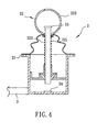
- another conventional electronic wheelchair 1 includes a direction controller 11 for sending signals to a driving control unit (not shown) to control driving operation of a wheel driving unit (not shown) in order to control in turn moving direction of the electronic wheelchair 1.
- the direction controller 11 includes a hollow base member 111, a circuit board 112 disposed in the base member 111, four angularly spaced apart lower sensing coils 113 disposed on the circuit board 112, a control stick 114 that extends pivotably through the base member 111 and that is disposed above and spaced apart from the circuit board 112, an upper sensing coil 115 mounted on a bottom end of the control stick 114, and a restoring spring 116 for biasing the control stick 114 to an initial non-operated position.
- the circuit board 112 generates direction signals corresponding to tilt of the upper sensing coil 115 relative to the lower sensing coils 113.
- the upper sensing coil 115 on the bottom end of the control stick 114 moves rearward relative to the lower sensing coils 113 on the circuit board 112, thereby enabling the circuit board 112 to generate a forward direction signal for driving forward movement of the electronic wheelchair 1.
- the upper sensing coil 115 on the bottom end of the control stick 114 moves forward relative to the lower sensing coils 113, thereby enabling the circuit board 112 to generate a rearward direction signal for driving rearward movement of the electronic wheelchair 1.
- the circuit board 112 generates one of left and right direction signals in the same manner upon pushing the control stick 114 to the left or to the right.
- the circuit board 112 is able to generate appropriate direction signals corresponding to magnitude and direction of tilt of the upper sensing coil 115 relative to the lower sensing coils 113 so that control of the electronic wheelchair 1 for making slight turns is possible.
- the power output of the wheel driving unit is not adjusted to correspond to actual road conditions.
- the power output of the wheel driving unit is not increased when the electronic wheelchair 1 is moving uphill and is not reduced when the electronic wheelchair 1 is moving downhill.
- use of the sensing coils 115, 113 results in a bulky design and complicates the manufacturing process.
- D1 discloses a direction and speed control device including all the technical features of the preamble of claim 1.
- the object of the present invention is to provide a direction and speed control device for an electronic wheelchair as claimed that can overcome the aforesaid drawbacks associated with the prior art.
- a direction and speed control device for an electronic wheelchair that includes a wheel unit, a wheel driving unit coupled to and driving rotation of the wheel unit, and a driving control circuit connected to and controlling driving operation of the wheel driving unit.
- the direction and speed control device comprises a base member, a manually operable pointing unit, first and second three-axis g acceleration sensors, and a control unit.
- the base member is adapted to be mounted on the electronic wheelchair.
- the pointing unit is mounted on the base member, and includes a control stick pivotable relative to the base member.
- the first three-axis g acceleration sensor is mounted on the control stick, and is operable to generate a voltage output indicative of tilt of the control stick in three orthogonal axes.
- the second three-axis g acceleration sensor is mounted on the base member, and is operable to generate a voltage output indicative of tilt of the base member in the three orthogonal axes.
- the control unit is coupled to the first and second three-axis g acceleration sensors so as to receive the voltage outputs thereof, and is operable so as to process the voltage outputs of the first and second three-axis g acceleration sensors to generate corresponding control signals for enabling the driving control circuit to control the driving operation of the wheel driving unit in order to control in turn rotation direction and speed of the wheel unit.
- the first preferred embodiment of a direction and speed control device 2 is adapted for application to an electronic wheelchair 3.
- the electronic wheelchair 3 includes a wheel unit 33, a wheel driving unit 32 coupled to and driving rotation of the wheel unit 33, and a driving control circuit 35 connected to and controlling driving operation of the wheel driving unit 32.
- the driving control circuit 35 includes a first driving circuit 351 and a second driving circuit 352.
- the wheel unit 33 includes a left rear wheel 331, a right rear wheel 333, a left front wheel 332, and a right front wheel 334.
- the wheel driving unit 32 includes a first motor 321 and a second motor 322.
- the direction and speed control device 2 includes a hollow base member 21 adapted to be mounted on the electronic wheelchair 3, a manually operable pointing unit 22 mounted on the base member 21 and including a control stick 221 pivotable relative to the base member 21, a first three-axis g acceleration sensor 23 mounted on the control stick 221 and operable to generate a voltage output indicative of tilt of the control stick 221 in three orthogonal axes, a second three-axis g acceleration sensor 24 mounted on the base member 21 and operable to generate a voltage output indicative of tilt of the base member 21 in the three orthogonal axes, and a control unit 34 coupled to the first and second three-axis g acceleration sensors 23, 24 so as to receive the voltage outputs thereof, and operable so as to process the voltage outputs of the first and second three-axis g acceleration sensors 23, 24 to generate corresponding control signals for enabling the first and second driving circuits 351, 352 of the driving control circuit 35 to control the driving operation of the first and second motors 321, 322 of
- the first and second three-axis g acceleration sensors 23, 24 are G acceleration sensors available from Freescale Inc. under Model No. MMA7260Q.
- the first and second three-axis g acceleration sensors 23, 24 are capable of sensing on the X, Y and Z orthogonal axes, have an operating current of 3 ⁇ A in a sleep mode and 500 ⁇ A in a normal operating mode, and a working voltage ranging between 2.2 and 3.6 volts.
- the package profile of each of the first and second three-axis g acceleration sensors 23, 24 in this embodiment is 6 ⁇ 6 ⁇ 1.45 mm.
- the pointing unit 22 further includes a hollow handle 222 mounted on a top end of the control stick 221, and a restoring spring 223 sleeved on the control stick 221.
- the restoring spring 223 biases the control stick 221 to an initial non-operated position, and accumulates a restoring force when the control stick 221 pivots away from the initial non-operated position.
- the first three-axis g acceleration sensor 23 is disposed in the hollow handle 222, and the second three-axis g acceleration sensor 24 is disposed in the base member 21 under and spaced apart from the bottom end of the control stick 221.
- the voltage output components that indicate tilt of the control stick 221 and the base member 21 in the three orthogonal axes and that are generated by the first and second three-axis g acceleration sensors 23, 24 are represented by X1-Y1-Z1 and X2-Y2-Z2, respectively.
- the base voltage of each of the first and second three-axis g acceleration sensors 23, 24 is 2.5 volts.
- the control unit 34 processes the three-dimensional voltage outputs of the first and second three-axis g acceleration sensors 23, 24, and generates control signals corresponding to a vector difference of the X-axes (X1, X2) or a vector difference of the Y-axes (Y1, Y2) and a sign of the vector difference.
- the control signals are provided to the first and second driving circuits 351, 352 for driving the first motor 321 to rotate the left rear wheel 331 and for driving the second motor 322 to rotate the right rear wheel 333.
- the left front wheel 332 and the right front wheel 334 are passively driven through the left rear wheel 331 and the right rear wheel 333, and are not driven directly by the first and second motors 321, 322.
- the control unit 34 generates the control signals for causing the electronic wheelchair 3 to turn in a desired one of left and right directions according to the X-axis components of the voltage outputs of the first and second three-axis g acceleration sensors 23, 24. For instance, when the control stick 221 is pivoted toward the right, the first three-axis g acceleration sensor 23 disposed at the top end of the control stick 221 will also tilt to the right relative to the second three-axis g acceleration sensor 24. That is, the X1 voltage component ranges between 2.5 and 3 volts, while the X2 voltage component remains at the base voltage of 2.5 volts.
- control unit 34 is able to determine that the difference (X1-X2) between the X-axis voltage components of the voltage outputs of the first and second three-axis g acceleration sensors 23, 24 has a positive value (i.e., 0 ⁇ X1-X2 ⁇ 0.5 volt).
- the control unit 34 When (X1-X2) is between 0 and 0.25 volt, the control unit 34 is able to determine that the control stick 221 was moved slightly to the right, and sends corresponding control signals to the first and second driving circuits 351, 352 such that the first driving circuit 351 drives the first motor 321 to increase its motor speed while the second driving circuit 352 drives the second motor 322 to decrease its motor speed.
- the rotation speed of the left rear wheel 331 is increased, while the rotation speed of the right rear wheel 333 is decreased, thereby resulting in gradual turning of the electronic wheelchair 3 to the right.
- the smaller the difference between X1 and X2 the slower will be the turning speed of the electronic wheelchair 3.
- the control unit 34 When (X1-X2) is between 0.25 and 0. 5 volt, the control unit 34 is able to determine that the control stick 221 was moved to the right to a larger extent, and sends corresponding control signals to the first and second driving circuits 351, 352 such that the first driving circuit 351 drives the first motor 321 to rotate in the normal direction while the second driving circuit 352 drives the second motor 322 to rotate in the reverse direction.
- the left rear wheel 331 rotates in the normal direction while the right rear wheel 333 rotates in the reverse direction so as to result in faster turning of the electronic wheelchair 3 to the right.
- the larger the difference between X1 and X2 the faster will be the turning speed of the electronic wheelchair 3.
- the first three-axis g acceleration sensor 23 disposed at the top end of the control stick 221 will also tilt to the left relative to the second three-axis g acceleration sensor 24. That is, the X1 voltage component ranges between 2 and 2.5 volts, while the X2 voltage component remains at the base voltage of 2.5 volts.
- the control unit 34 is able to determine that the difference (X1-X2) between the X-axis voltage components of the voltage outputs of the first and second three-axis g acceleration sensors 23, 24 has a negative value (i.e., -0.5 volt ⁇ X1-X2 ⁇ 0).
- the control unit 34 When (X1- X2) is between -0. 25 and 0 volt, the control unit 34 is able to determine that the control stick 221 was moved slightly to the left, and sends corresponding control signals to the first and second driving circuits 351, 352 such that the first driving circuit 351 drives the first motor 321 to decrease its motor speed while the second driving circuit 352 drives the second motor 322 to increase its motor speed.
- the rotation speed of the left rear wheel 331 is decreased, while the rotation speed of the right rear wheel 333 is increased, thereby resulting in gradual turning of the electronic wheelchair 3 to the left.
- the smaller the difference between X1 and X2 the slower will be the turning speed of the electronic wheelchair 3.
- the control unit 34 When (X1-X2) is between -0.5 and -0.25 volt, the control unit 34 is able to determine that the control stick 221 was moved to the left to a larger extent, and sends corresponding control signals to the first and second driving circuits 351, 352 such that the first driving circuit 351 drives the first motor 321 to rotate in the reverse direction while the second driving circuit 352 drives the second motor 322 to rotate in the normal direction.
- the left rear wheel 331 rotates in the reverse direction while the right rear wheel 333 rotates in the normal direction so as to result in faster turning of the electronic wheelchair 3 to the left.
- the larger the difference between X1 and X2 the faster will be the turning speed of the electronic wheelchair 3.
- the control unit 34 generates the control signals for causing the electronic wheelchair 3 to move in a desired one of forward and rearward directions according to the Y-axis components of the voltage outputs of the first and second three-axis g acceleration sensors 23, 24.
- the first three-axis g acceleration sensor 23 disposed at the top end of the control stick 221 will also tilt forward relative to the second three-axis g acceleration sensor 24. That is, the Y1 voltage component ranges between 2.5 and 3 volts, while the Y2 voltage component remains at the base voltage of 2.5 volts.
- control unit 34 is able to determine that the difference (Y1-Y2) between the Y-axis voltage components of the voltage outputs of the first and second three-axis g acceleration sensors 23, 24 has a positive value (i.e., 0 ⁇ Y1-Y2 ⁇ 0.5 volt).
- control unit 34 sends corresponding control signals to the first and second driving circuits 351, 352 for driving the first and second motors 321, 322 to rotate in the normal direction, thereby causing the electronic wheelchair 3 to the move forward.
- the first three-axis g acceleration sensor 23 disposed at the top end of the control stick 221 will also tilt rearward relative to the second three-axis g acceleration sensor 24. That is, the Y1 voltage component ranges between 2 and 2.5 volts, while the Y2 voltage component remains at the base voltage of 2.5 volts.
- the control unit 34 is able to determine that the difference (Y1-Y2) between the Y-axis voltage components of the voltage outputs of the first and second three-axis g acceleration sensors 23, 24 has a negative value (i.e., -0.5 volt ⁇ Y1-Y2 ⁇ 0).
- control unit 34 sends corresponding control signals to the first and second driving circuits 351, 352 for driving the first and second motors 321, 322 to rotate in the reverse direction, thereby causing the electronic wheelchair 3 to the move rearward.
- the control unit 34 determines that the electronic wheelchair 3 is moving uphill when the Z-axis component of the voltage output of each of the first and second three-axis g acceleration sensors 23, 24 is larger than a base Z-axis voltage (2.5 volts), i.e., Z1 and Z2 have values ranging between 2.5 and 3 volts.
- the control unit 34 sends corresponding control signals to the first and second driving circuits 351, 352 to increase rotation speed so as to result in sufficient motive power for the electronic wheelchair 3 to go uphill.
- control unit 34 determines that the electronic wheelchair 3 is moving downhill when the Z-axis component of the voltage output of each of the first and second three-axis g acceleration sensors 23, 24 is smaller than the base Z-axis voltage, i.e., Z1 and Z2 have values ranging between 2 and 2.5 volts.
- control unit 34 sends control signals to the first and second driving circuits 351, 352 to decrease rotation speed so as to reduce motive power for the electronic wheelchair 3 when the latter moves downhill.
- the Y-axis component (Y1, Y2) of the voltage output of each of the first and second three-axis g acceleration sensors 23, 24 will undesirably deviate from the base Y-axis voltage (2.5 volts) when the electronic wheelchair 3 is moving uphill or downhill.
- the control unit 34 is able to detect uphill or downhill movement of the electronic wheelchair 3 from the Z-axis component (Z1, Z2) of the voltage output of each of the first and second three-axis g acceleration sensors 23, 24, the control unit 34 is able to determine that the deviations in the Y-axis components (Y1, Y2) are due to uphill or downhill movement so as to avoid undesired changes in moving speed of the electronic wheelchair 3.
- the control unit 34 When the electronic wheelchair 3 is overturned, the control unit 34 is able to detect that the Z-axis component of the voltage output of each of the first and second three-axis g acceleration sensors 23, 24 is outside a normal operating voltage range (2 to 3 volts) . That is, both Z1, Z2 are either smaller than 2 volts or larger than 3 volts. In this case, the control unit 34 sends control signals to the first and second driving circuits 351, 352 to stop operation of the first and second motors 321, 322, thereby interrupting supply of motive power automatically when the electronic wheelchair 3 is overturned.
- the restoring spring 223 accumulates a restoring force whenever the control stick 221 is moved away from the initial non-operatedposition.
- the control stick 221 can be restored automatically to the non-operated position once the control stick 221 is released, thereby resulting in termination of the supply of motive power in the electronic wheelchair 3 when the control stick 3 is released to promote user safety.
- first and second three-axis g acceleration sensors 23, 24 operate under low current conditions (such as 500 ⁇ A)
- power consumption can be kept low in the direction and speed control device 2 of this invention.
- the second preferred embodiment of this invention is shown to differ from the previous embodiment in that the first three-axis g acceleration sensor 23 is mounted on a bottom end 2211 of the control stick 221.
- the direction of movement of the first three-axis g acceleration sensor 23 is opposite to that of the handle 222 on the control stick 221. Therefore, the control signals sent by the control unit 34 in this embodiment are opposite to those sent in the previous embodiment.
- the control unit 34 of this embodiment will send left turn control signals instead of right turn control signals.
- the control unit 34 of this embodiment will send right turn control signals instead of left turn control signals.
- the control unit 34 of this embodiment will send rearward control signals instead of forward control signals.
- (Y1-Y2) has a negative value
- the control unit 34 of this embodiment will send forward control signals instead of rearward control signals.
Claims (13)
- Dispositif (2) de commande de direction et de vitesse pour un fauteuil roulant électronique (3), le fauteuil roulant électronique (3) comprenant une unité de roues (33), une unité (32) d'entraînement de roues couplée à l'unité de roues (33) et l'entraînant en rotation, et un circuit (35) de commande d'entraînement connecté à et commandant l'opération d'entraînement de l'unité (32) d'entraînement de roues, ledit dispositif de commande (2) comportant :un élément de base (21) conçu pour être monté sur le fauteuil roulant électronique (3) ;une unité (22) de braquage pouvant être manoeuvrée manuellement, montée sur ledit élément de base (21) et comprenant une manette de commande (221) pouvant pivoter par rapport audit élément de base (21) ;caractérisé par :un premier capteur (23) d'accélération g à trois axes monté sur ladite manette de commande (221) et pouvant être actionné pour générer une tension de sortie représentative d'une inclinaison de ladite manette de commande (221) dans trois axes orthogonaux ;un deuxième capteur (24) d'accélération g à trois axes monté sur ledit élément de base (21) et pouvant être actionné pour générer une tension de sortie représentative d'une inclinaison dudit élément de base (21) dans les trois axe orthogonaux ; etune unité de commande (34) couplée auxdits premier et deuxième capteurs (23, 24) d'accélération g à trois axes afin d'en recevoir les tensions de sortie, et pouvant être mise en oeuvre afin de traiter les tensions de sortie desdits premier et deuxième capteurs (23, 24) d'accélération g à trois axes pour générer des signaux de commande correspondants afin de permettre au circuit (35) de commande d'entraînement de commander l'opération d'entraînement de l'unité (32) d'entraînement de roues pour commander, à son tour, la direction et la vitesse de rotation de l'unité de roues (33).
- Dispositif (2) de commande de direction et de vitesse selon la revendication 1, caractérisé en ce que ladite unité de commande (34) détermine que le fauteuil roulant électronique (3) se déplace en montant lorsqu'une composante d'axe Z de la tension de sortie de chacun desdits premier et second capteurs (23, 24) d'accélération g à trois axes est plus grande qu'une tension d'axe Z de base, et détermine en outre que le fauteuil roulant électronique (3) se déplace en descendant lorsque la composante d'axe Z de la tension de sortie de chacun desdits premier et deuxième capteurs (23, 24) d'accélération g à trois axes est inférieure à la tension d'axe Z de base.
- Dispositif (2) de commande de direction et de vitesse selon l'une des revendications 1 et 2, caractérisé en ce que ladite unité de commande (34) génère les signaux de commande pour amener le fauteuil roulant électronique (3) à tourner dans l'une, souhaitée, de directions de gauche et de droite conformément à des composantes d'axes X des tensions de sortie desdits premier et deuxième capteurs (23, 24) d'accélération g à trois axes.
- Dispositif (2) de commande de direction et de vitesse selon la revendication 3, caractérisé en outre en ce que ladite unité de commande (34) génère les signaux de commande pour amener le fauteuil roulant électronique (3) à tourner vers la droite lorsqu'une différence entre les composantes d'axes X des tensions de sortie desdits premier et deuxième capteurs (23, 24) d'accélération g à trois axes a une valeur positive, et génère en outre les signaux de commande pour amener le fauteuil roulant électronique (3) à tourner à gauche lorsque la différence entre les composantes d'axes X des tensions de sortie desdits premier et deuxième capteurs (23, 24) d'accélération g à trois axes a une valeur négative.
- Dispositif (2) de commande de direction et de vitesse selon la revendication 4, caractérisé en outre en ce que ladite unité de commande (34) génère les signaux de commande pour commander la vitesse à laquelle tourne le fauteuil roulant électronique (3) dans l'une, souhaitée, des directions de gauche et de droite conformément à une grandeur d'une valeur absolue de la différence entre les composantes d'axes X des tensions de sortie desdits premier et deuxième capteurs (23, 24) d'accélération g à trois axes.
- Dispositif (2) de commande de direction et de vitesse selon la revendication 5, caractérisé en outre en ce que ladite unité de commande (34) génère les signaux de commande pour augmenter la vitesse à laquelle tourne le fauteuil roulant électronique (3) dans l'une, souhaitée, des directions de gauche et de droite lorsque la grandeur de la valeur absolue de la différence entre les composantes d'axes X des tensions de sortie desdits premier et deuxième capteurs (23, 24) d'accélération g à trois axes augmente, et génère en outre les signaux de commande pour réduire la vitesse à laquelle tourne le fauteuil roulant électronique (3) dans l'une, souhaitée, des directions de gauche et de droite lorsque la grandeur de la valeur absolue de la différence entre les composantes d'axes X des tensions de sortie desdits premier et deuxième capteurs (23, 24) d'accélération g à trois axes diminue.
- Dispositif (2) de commande de direction et de vitesse selon l'une quelconque des revendications 1 à 6, caractérisé en ce que ladite unité de commande (34) génère les signaux de commande pour amener la fauteuil roulant électronique (3) à se déplacer dans l'une, souhaitée, de directions avant et arrière conformément à des composantes d'axes Y des tensions de sortie desdits premier et deuxième capteurs (23, 24) d'accélération g à trois axes.
- Dispositif (2) de commande de direction et de vitesse selon la revendication 7, caractérisé en outre en ce que ladite unité de commande (34) génère les signaux de commande pour amener le fauteuil roulant électronique (3) à se déplacer vers l'avant lorsqu'une différence entre les composantes d'axes Y des tensions de sortie desdits premier et deuxième capteurs (23, 24) d'accélération g à trois axes à une valeur positive, et génère en outre les signaux de commande pour amener le fauteuil roulant électronique (3) à se déplacer vers l'arrière lorsque la différence entre les composantes d'axes Y des tensions de sortie desdits premier et deuxième capteurs (23, 24) d'accélération g à trois axes a une valeur négative.
- Dispositif (2) de commande de direction et de vitesse selon la revendication 8, caractérisé en outre en ce que ladite unité de commande (34) génère les signaux de commande pour commander la vitesse de déplacement du fauteuil roulant électronique (3) dans l'une, souhaitée, des directions avant et arrière conformément à la grandeur d'une valeur absolue de la différence entre les composantes d'axes Y des tensions de sortie desdits premier et deuxième capteurs (23, 24) d'accélération g à trois axes.
- Dispositif (2) de commande de direction et de vitesse selon la revendication 9, caractérisé en outre en ce que ladite unité de commande (34) génère les signaux de commande pour augmenter la vitesse de déplacement du fauteuil roulant électronique (3) dans l'une, souhaitée, des directions avant et arrière lorsque la grandeur de la valeur absolue de la différence entre les composantes d'axes Y des tensions de sortie desdits premier et deuxième capteurs (23, 24) d'accélération g à trois axes augmente, et génère en outre les signaux de commande pour réduire la vitesse de déplacement du fauteuil roulant électronique (3) dans l'une, souhaitée, des directions avant et arrière lorsque la grandeur de la valeur absolue de la différence entre les composantes d'axes Y des tensions de sortie desdits premier et deuxième capteurs (23, 24) d'accélération g à trois axes diminue.
- Dispositif (2) de commande de direction et de vitesse selon l'une quelconque des revendications 1 à 10, caractérisé en ce que ladite unité de braquage (22) pouvant être manoeuvrée manuellement comprend en outre une poignée creuse (222) montée sur une extrémité supérieure de ladite manette de commande (221) et dans laquelle est disposé ledit premier capteur (23) d'accélération g à trois axes.
- Dispositif (2) de commande de direction et de vitesse selon l'une quelconque des revendications 1 à 10, caractérisé en ce que ledit premier capteur (23) d'accélération g à trois axes est monté sur une extrémité inférieure (2211) de ladite manette de commande (221).
- Dispositif (2) de commande de direction et de vitesse selon la revendication 11 ou la revendication 12, caractérisé en ce que ladite unité de braquage (22) pouvant être manoeuvrée manuellement comprend en outre un ressort de rappel (223) destiné à rappeler ladite manette de commande (221) vers une position initiale non actionnée.
Priority Applications (4)
| Application Number | Priority Date | Filing Date | Title |
|---|---|---|---|
| DE200760001231 DE602007001231D1 (de) | 2007-03-20 | 2007-03-20 | Richtungs- und Geschwindigkeitskontrollvorrichtung für einen elektronischen Rollstuhl |
| EP07005658A EP1972314B1 (fr) | 2006-12-25 | 2007-03-20 | Dispositif pour la commande de la direction et de la vitesse d'une chaise roulante électronique |
| AT07005658T ATE432681T1 (de) | 2006-12-25 | 2007-03-20 | Richtungs- und geschwindigkeitskontrollvorrichtung für einen elektronischen rollstuhl |
| US12/002,018 US7974753B2 (en) | 2006-12-25 | 2007-12-14 | Direction and speed control device for an electronic wheelchair |
Applications Claiming Priority (2)
| Application Number | Priority Date | Filing Date | Title |
|---|---|---|---|
| TW95148752A TW200826912A (en) | 2006-12-25 | 2006-12-25 | Direction/speed controller of electrically-driven wheelchair |
| EP07005658A EP1972314B1 (fr) | 2006-12-25 | 2007-03-20 | Dispositif pour la commande de la direction et de la vitesse d'une chaise roulante électronique |
Publications (2)
| Publication Number | Publication Date |
|---|---|
| EP1972314A1 EP1972314A1 (fr) | 2008-09-24 |
| EP1972314B1 true EP1972314B1 (fr) | 2009-06-03 |
Family
ID=40174826
Family Applications (1)
| Application Number | Title | Priority Date | Filing Date |
|---|---|---|---|
| EP07005658A Not-in-force EP1972314B1 (fr) | 2006-12-25 | 2007-03-20 | Dispositif pour la commande de la direction et de la vitesse d'une chaise roulante électronique |
Country Status (3)
| Country | Link |
|---|---|
| US (1) | US7974753B2 (fr) |
| EP (1) | EP1972314B1 (fr) |
| AT (1) | ATE432681T1 (fr) |
Families Citing this family (11)
| Publication number | Priority date | Publication date | Assignee | Title |
|---|---|---|---|---|
| US7931101B2 (en) * | 2006-10-13 | 2011-04-26 | Invacare Corporation | Proportional joystick with integral switch |
| EP1972486A1 (fr) | 2007-03-19 | 2008-09-24 | Invacare International Sàrl | Fauteuil roulant motorisé |
| US8315770B2 (en) * | 2007-11-19 | 2012-11-20 | Invacare Corporation | Motorized wheelchair |
| DE102009042091A1 (de) * | 2009-09-18 | 2011-03-24 | Spohn+Burkhardt Gmbh & Co. | Schalthebel mit Beschleunigungssensor |
| GB2478957B (en) * | 2010-03-24 | 2014-07-09 | Penny & Giles Controls Ltd | A controller and control method for a motorised vehicle |
| US20130038179A1 (en) * | 2011-08-08 | 2013-02-14 | Honeywell International Inc. | Landing gear with integrated electric motor for electric taxi system |
| US10384558B2 (en) * | 2016-09-27 | 2019-08-20 | STG Consulting Co., Ltd. | Cruise control system for electrical mobility scooter and electrical mobility scooter therewith |
| US10864127B1 (en) | 2017-05-09 | 2020-12-15 | Pride Mobility Products Corporation | System and method for correcting steering of a vehicle |
| JP6791014B2 (ja) * | 2017-05-29 | 2020-11-25 | トヨタ自動車株式会社 | 電動車椅子操作装置及びその車両操作方法 |
| US11628105B2 (en) | 2020-06-25 | 2023-04-18 | Toyota Motor North America, Inc. | Powered wheelchairs and methods for maintaining a powered wheelchair in a pre-selected position |
| US20220236760A1 (en) * | 2021-01-27 | 2022-07-28 | Curtis Instruments Inc. | Joystick with Adjustable Operating Force for Electrical Wheelchair Devices |
Family Cites Families (6)
| Publication number | Priority date | Publication date | Assignee | Title |
|---|---|---|---|---|
| US4387325A (en) * | 1981-04-15 | 1983-06-07 | Invacare Corporation | Electric wheelchair with speed control circuit |
| US6615937B2 (en) * | 1999-07-30 | 2003-09-09 | Invacare Corporation | Motorized wheelchairs |
| US6202773B1 (en) * | 1999-07-30 | 2001-03-20 | Invacare Corporation | Motorized wheelchairs |
| DE60319847T2 (de) * | 2002-08-29 | 2009-09-10 | Department Of Veterans Affairs, Rehabilitation R&D Service | Joystick mit variabler nachgiebigkeit mit kompensationsalgorithmen |
| US7404463B2 (en) * | 2004-09-30 | 2008-07-29 | Honda Motor Co., Ltd. | Motorcycle radiator arranging construction |
| TWI285547B (en) * | 2005-02-16 | 2007-08-21 | Kwang Yang Motor Co | Fixed speed control device of electric wheelchair |
-
2007
- 2007-03-20 AT AT07005658T patent/ATE432681T1/de not_active IP Right Cessation
- 2007-03-20 EP EP07005658A patent/EP1972314B1/fr not_active Not-in-force
- 2007-12-14 US US12/002,018 patent/US7974753B2/en not_active Expired - Fee Related
Also Published As
| Publication number | Publication date |
|---|---|
| ATE432681T1 (de) | 2009-06-15 |
| US7974753B2 (en) | 2011-07-05 |
| US20080154463A1 (en) | 2008-06-26 |
| EP1972314A1 (fr) | 2008-09-24 |
Similar Documents
| Publication | Publication Date | Title |
|---|---|---|
| EP1972314B1 (fr) | Dispositif pour la commande de la direction et de la vitesse d'une chaise roulante électronique | |
| US9457861B2 (en) | Inverted pendulum type vehicle | |
| WO2019184983A1 (fr) | Tondeuse à gazon à conducteur porté et son dispositif d'actionnement | |
| US8352170B2 (en) | Traveling apparatus and method of controlling parallel two-wheeled vehicle | |
| US8447506B2 (en) | Traveling device and its control method | |
| EP2664528B1 (fr) | Véhicule à pendule inversé | |
| WO2009008292A1 (fr) | Corps mobile de type à roue inversée et son procédé de commande | |
| US9474678B2 (en) | Pushcart | |
| JP2005022631A5 (fr) | ||
| JP2003011863A (ja) | 自動二輪車 | |
| JP2011201386A (ja) | 移動体及び移動体の制御方法 | |
| WO2011013217A1 (fr) | Système de commande de direction | |
| JP2015128991A (ja) | 手押し車 | |
| JP5113138B2 (ja) | 電子玩具及びその移動方法 | |
| KR101878690B1 (ko) | 주차 동작 제어 장치 및 그 제어 방법 | |
| JP6559939B2 (ja) | 電動補助自転車 | |
| CN107902031B (zh) | 一种电子刹车方法、车架、动力驱动组件及车辆 | |
| CN106476964B (zh) | 一种通过姿态转向的电动车 | |
| JP2007118833A (ja) | 操舵制御装置及びステアリング保持位置検出装置 | |
| JP2016049950A (ja) | 倒立二輪型移動体及びその制御方法 | |
| CN219651333U (zh) | 一种体感车的底盘装置 | |
| US9701358B2 (en) | Inverted moving body | |
| CN115384671B (zh) | 一种可单脚操控的两轮电动平衡车及操作方法 | |
| CN115320766A (zh) | 一种可单脚操控的两轮电动平衡车及操作方法 | |
| JP6699443B2 (ja) | 走行装置 |
Legal Events
| Date | Code | Title | Description |
|---|---|---|---|
| PUAI | Public reference made under article 153(3) epc to a published international application that has entered the european phase |
Free format text: ORIGINAL CODE: 0009012 |
|
| AK | Designated contracting states |
Kind code of ref document: A1 Designated state(s): AT BE BG CH CY CZ DE DK EE ES FI FR GB GR HU IE IS IT LI LT LU LV MC MT NL PL PT RO SE SI SK TR |
|
| AX | Request for extension of the european patent |
Extension state: AL BA HR MK RS |
|
| 17P | Request for examination filed |
Effective date: 20080912 |
|
| GRAP | Despatch of communication of intention to grant a patent |
Free format text: ORIGINAL CODE: EPIDOSNIGR1 |
|
| GRAS | Grant fee paid |
Free format text: ORIGINAL CODE: EPIDOSNIGR3 |
|
| GRAA | (expected) grant |
Free format text: ORIGINAL CODE: 0009210 |
|
| AKX | Designation fees paid |
Designated state(s): AT BE BG CH CY CZ DE DK EE ES FI FR GB GR HU IE IS IT LI LT LU LV MC MT NL PL PT RO SE SI SK TR |
|
| AK | Designated contracting states |
Kind code of ref document: B1 Designated state(s): AT BE BG CH CY CZ DE DK EE ES FI FR GB GR HU IE IS IT LI LT LU LV MC MT NL PL PT RO SE SI SK TR |
|
| REG | Reference to a national code |
Ref country code: GB Ref legal event code: FG4D |
|
| REG | Reference to a national code |
Ref country code: CH Ref legal event code: EP |
|
| REG | Reference to a national code |
Ref country code: IE Ref legal event code: FG4D |
|
| REF | Corresponds to: |
Ref document number: 602007001231 Country of ref document: DE Date of ref document: 20090716 Kind code of ref document: P |
|
| PG25 | Lapsed in a contracting state [announced via postgrant information from national office to epo] |
Ref country code: LT Free format text: LAPSE BECAUSE OF FAILURE TO SUBMIT A TRANSLATION OF THE DESCRIPTION OR TO PAY THE FEE WITHIN THE PRESCRIBED TIME-LIMIT Effective date: 20090603 Ref country code: AT Free format text: LAPSE BECAUSE OF FAILURE TO SUBMIT A TRANSLATION OF THE DESCRIPTION OR TO PAY THE FEE WITHIN THE PRESCRIBED TIME-LIMIT Effective date: 20090603 Ref country code: FI Free format text: LAPSE BECAUSE OF FAILURE TO SUBMIT A TRANSLATION OF THE DESCRIPTION OR TO PAY THE FEE WITHIN THE PRESCRIBED TIME-LIMIT Effective date: 20090603 |
|
| NLV1 | Nl: lapsed or annulled due to failure to fulfill the requirements of art. 29p and 29m of the patents act | ||
| PG25 | Lapsed in a contracting state [announced via postgrant information from national office to epo] |
Ref country code: LV Free format text: LAPSE BECAUSE OF FAILURE TO SUBMIT A TRANSLATION OF THE DESCRIPTION OR TO PAY THE FEE WITHIN THE PRESCRIBED TIME-LIMIT Effective date: 20090603 Ref country code: SE Free format text: LAPSE BECAUSE OF FAILURE TO SUBMIT A TRANSLATION OF THE DESCRIPTION OR TO PAY THE FEE WITHIN THE PRESCRIBED TIME-LIMIT Effective date: 20090903 Ref country code: SI Free format text: LAPSE BECAUSE OF FAILURE TO SUBMIT A TRANSLATION OF THE DESCRIPTION OR TO PAY THE FEE WITHIN THE PRESCRIBED TIME-LIMIT Effective date: 20090603 Ref country code: PL Free format text: LAPSE BECAUSE OF FAILURE TO SUBMIT A TRANSLATION OF THE DESCRIPTION OR TO PAY THE FEE WITHIN THE PRESCRIBED TIME-LIMIT Effective date: 20090603 Ref country code: NL Free format text: LAPSE BECAUSE OF FAILURE TO SUBMIT A TRANSLATION OF THE DESCRIPTION OR TO PAY THE FEE WITHIN THE PRESCRIBED TIME-LIMIT Effective date: 20090603 |
|
| PG25 | Lapsed in a contracting state [announced via postgrant information from national office to epo] |
Ref country code: EE Free format text: LAPSE BECAUSE OF FAILURE TO SUBMIT A TRANSLATION OF THE DESCRIPTION OR TO PAY THE FEE WITHIN THE PRESCRIBED TIME-LIMIT Effective date: 20090603 Ref country code: CZ Free format text: LAPSE BECAUSE OF FAILURE TO SUBMIT A TRANSLATION OF THE DESCRIPTION OR TO PAY THE FEE WITHIN THE PRESCRIBED TIME-LIMIT Effective date: 20090603 Ref country code: ES Free format text: LAPSE BECAUSE OF FAILURE TO SUBMIT A TRANSLATION OF THE DESCRIPTION OR TO PAY THE FEE WITHIN THE PRESCRIBED TIME-LIMIT Effective date: 20090914 Ref country code: RO Free format text: LAPSE BECAUSE OF FAILURE TO SUBMIT A TRANSLATION OF THE DESCRIPTION OR TO PAY THE FEE WITHIN THE PRESCRIBED TIME-LIMIT Effective date: 20090603 Ref country code: IS Free format text: LAPSE BECAUSE OF FAILURE TO SUBMIT A TRANSLATION OF THE DESCRIPTION OR TO PAY THE FEE WITHIN THE PRESCRIBED TIME-LIMIT Effective date: 20091003 |
|
| PG25 | Lapsed in a contracting state [announced via postgrant information from national office to epo] |
Ref country code: SK Free format text: LAPSE BECAUSE OF FAILURE TO SUBMIT A TRANSLATION OF THE DESCRIPTION OR TO PAY THE FEE WITHIN THE PRESCRIBED TIME-LIMIT Effective date: 20090603 Ref country code: BE Free format text: LAPSE BECAUSE OF FAILURE TO SUBMIT A TRANSLATION OF THE DESCRIPTION OR TO PAY THE FEE WITHIN THE PRESCRIBED TIME-LIMIT Effective date: 20090603 |
|
| PG25 | Lapsed in a contracting state [announced via postgrant information from national office to epo] |
Ref country code: PT Free format text: LAPSE BECAUSE OF FAILURE TO SUBMIT A TRANSLATION OF THE DESCRIPTION OR TO PAY THE FEE WITHIN THE PRESCRIBED TIME-LIMIT Effective date: 20091003 Ref country code: BG Free format text: LAPSE BECAUSE OF FAILURE TO SUBMIT A TRANSLATION OF THE DESCRIPTION OR TO PAY THE FEE WITHIN THE PRESCRIBED TIME-LIMIT Effective date: 20090903 |
|
| PLBE | No opposition filed within time limit |
Free format text: ORIGINAL CODE: 0009261 |
|
| STAA | Information on the status of an ep patent application or granted ep patent |
Free format text: STATUS: NO OPPOSITION FILED WITHIN TIME LIMIT |
|
| PG25 | Lapsed in a contracting state [announced via postgrant information from national office to epo] |
Ref country code: DK Free format text: LAPSE BECAUSE OF FAILURE TO SUBMIT A TRANSLATION OF THE DESCRIPTION OR TO PAY THE FEE WITHIN THE PRESCRIBED TIME-LIMIT Effective date: 20090603 |
|
| 26N | No opposition filed |
Effective date: 20100304 |
|
| PG25 | Lapsed in a contracting state [announced via postgrant information from national office to epo] |
Ref country code: MC Free format text: LAPSE BECAUSE OF NON-PAYMENT OF DUE FEES Effective date: 20100331 Ref country code: GR Free format text: LAPSE BECAUSE OF FAILURE TO SUBMIT A TRANSLATION OF THE DESCRIPTION OR TO PAY THE FEE WITHIN THE PRESCRIBED TIME-LIMIT Effective date: 20090904 |
|
| REG | Reference to a national code |
Ref country code: IE Ref legal event code: MM4A |
|
| REG | Reference to a national code |
Ref country code: FR Ref legal event code: ST Effective date: 20101130 |
|
| PG25 | Lapsed in a contracting state [announced via postgrant information from national office to epo] |
Ref country code: FR Free format text: LAPSE BECAUSE OF NON-PAYMENT OF DUE FEES Effective date: 20100331 Ref country code: IE Free format text: LAPSE BECAUSE OF NON-PAYMENT OF DUE FEES Effective date: 20100320 |
|
| PG25 | Lapsed in a contracting state [announced via postgrant information from national office to epo] |
Ref country code: DE Free format text: LAPSE BECAUSE OF NON-PAYMENT OF DUE FEES Effective date: 20101001 |
|
| PG25 | Lapsed in a contracting state [announced via postgrant information from national office to epo] |
Ref country code: IT Free format text: LAPSE BECAUSE OF FAILURE TO SUBMIT A TRANSLATION OF THE DESCRIPTION OR TO PAY THE FEE WITHIN THE PRESCRIBED TIME-LIMIT Effective date: 20090603 |
|
| PG25 | Lapsed in a contracting state [announced via postgrant information from national office to epo] |
Ref country code: MT Free format text: LAPSE BECAUSE OF FAILURE TO SUBMIT A TRANSLATION OF THE DESCRIPTION OR TO PAY THE FEE WITHIN THE PRESCRIBED TIME-LIMIT Effective date: 20090603 |
|
| REG | Reference to a national code |
Ref country code: CH Ref legal event code: PL |
|
| PG25 | Lapsed in a contracting state [announced via postgrant information from national office to epo] |
Ref country code: CH Free format text: LAPSE BECAUSE OF NON-PAYMENT OF DUE FEES Effective date: 20110331 Ref country code: LI Free format text: LAPSE BECAUSE OF NON-PAYMENT OF DUE FEES Effective date: 20110331 |
|
| PG25 | Lapsed in a contracting state [announced via postgrant information from national office to epo] |
Ref country code: CY Free format text: LAPSE BECAUSE OF FAILURE TO SUBMIT A TRANSLATION OF THE DESCRIPTION OR TO PAY THE FEE WITHIN THE PRESCRIBED TIME-LIMIT Effective date: 20090603 |
|
| PG25 | Lapsed in a contracting state [announced via postgrant information from national office to epo] |
Ref country code: LU Free format text: LAPSE BECAUSE OF NON-PAYMENT OF DUE FEES Effective date: 20100320 Ref country code: HU Free format text: LAPSE BECAUSE OF FAILURE TO SUBMIT A TRANSLATION OF THE DESCRIPTION OR TO PAY THE FEE WITHIN THE PRESCRIBED TIME-LIMIT Effective date: 20091204 |
|
| PG25 | Lapsed in a contracting state [announced via postgrant information from national office to epo] |
Ref country code: TR Free format text: LAPSE BECAUSE OF FAILURE TO SUBMIT A TRANSLATION OF THE DESCRIPTION OR TO PAY THE FEE WITHIN THE PRESCRIBED TIME-LIMIT Effective date: 20090603 |
|
| PGFP | Annual fee paid to national office [announced via postgrant information from national office to epo] |
Ref country code: GB Payment date: 20130204 Year of fee payment: 7 |
|
| GBPC | Gb: european patent ceased through non-payment of renewal fee |
Effective date: 20140320 |
|
| PG25 | Lapsed in a contracting state [announced via postgrant information from national office to epo] |
Ref country code: GB Free format text: LAPSE BECAUSE OF NON-PAYMENT OF DUE FEES Effective date: 20140320 |