EP1972178B1 - Electrostatic loudspeakers - Google Patents
Electrostatic loudspeakers Download PDFInfo
- Publication number
- EP1972178B1 EP1972178B1 EP06820693.7A EP06820693A EP1972178B1 EP 1972178 B1 EP1972178 B1 EP 1972178B1 EP 06820693 A EP06820693 A EP 06820693A EP 1972178 B1 EP1972178 B1 EP 1972178B1
- Authority
- EP
- European Patent Office
- Prior art keywords
- membrane
- loudspeaker according
- membranes
- loudspeaker
- outer membranes
- Prior art date
- Legal status (The legal status is an assumption and is not a legal conclusion. Google has not performed a legal analysis and makes no representation as to the accuracy of the status listed.)
- Active
Links
- 239000012528 membrane Substances 0.000 claims description 55
- 239000000463 material Substances 0.000 claims description 4
- 239000011159 matrix material Substances 0.000 claims description 2
- 238000005513 bias potential Methods 0.000 claims 3
- 230000008901 benefit Effects 0.000 description 5
- 238000001465 metallisation Methods 0.000 description 4
- 239000000123 paper Substances 0.000 description 4
- 229920005597 polymer membrane Polymers 0.000 description 4
- 230000005236 sound signal Effects 0.000 description 3
- 238000010276 construction Methods 0.000 description 2
- 238000010586 diagram Methods 0.000 description 2
- 230000005684 electric field Effects 0.000 description 2
- 230000005284 excitation Effects 0.000 description 2
- 238000000034 method Methods 0.000 description 2
- 239000011148 porous material Substances 0.000 description 2
- 230000008569 process Effects 0.000 description 2
- 230000004044 response Effects 0.000 description 2
- 239000010409 thin film Substances 0.000 description 2
- RYGMFSIKBFXOCR-UHFFFAOYSA-N Copper Chemical compound [Cu] RYGMFSIKBFXOCR-UHFFFAOYSA-N 0.000 description 1
- 239000004411 aluminium Substances 0.000 description 1
- XAGFODPZIPBFFR-UHFFFAOYSA-N aluminium Chemical compound [Al] XAGFODPZIPBFFR-UHFFFAOYSA-N 0.000 description 1
- 229910052782 aluminium Inorganic materials 0.000 description 1
- 239000005030 aluminium foil Substances 0.000 description 1
- 239000002801 charged material Substances 0.000 description 1
- 239000011248 coating agent Substances 0.000 description 1
- 238000000576 coating method Methods 0.000 description 1
- 239000011889 copper foil Substances 0.000 description 1
- 208000018999 crinkle Diseases 0.000 description 1
- 238000000151 deposition Methods 0.000 description 1
- 230000008021 deposition Effects 0.000 description 1
- 238000006073 displacement reaction Methods 0.000 description 1
- 230000000694 effects Effects 0.000 description 1
- 230000005686 electrostatic field Effects 0.000 description 1
- 239000004744 fabric Substances 0.000 description 1
- 239000011888 foil Substances 0.000 description 1
- 239000011084 greaseproof paper Substances 0.000 description 1
- 230000007246 mechanism Effects 0.000 description 1
- 239000003973 paint Substances 0.000 description 1
- 239000004033 plastic Substances 0.000 description 1
- 229920000642 polymer Polymers 0.000 description 1
- 229920006254 polymer film Polymers 0.000 description 1
- 230000009467 reduction Effects 0.000 description 1
- 239000011435 rock Substances 0.000 description 1
- 238000007650 screen-printing Methods 0.000 description 1
- 238000000926 separation method Methods 0.000 description 1
- 125000006850 spacer group Chemical group 0.000 description 1
- 238000013316 zoning Methods 0.000 description 1
Images
Classifications
-
- H—ELECTRICITY
- H04—ELECTRIC COMMUNICATION TECHNIQUE
- H04R—LOUDSPEAKERS, MICROPHONES, GRAMOPHONE PICK-UPS OR LIKE ACOUSTIC ELECTROMECHANICAL TRANSDUCERS; DEAF-AID SETS; PUBLIC ADDRESS SYSTEMS
- H04R19/00—Electrostatic transducers
- H04R19/02—Loudspeakers
-
- H—ELECTRICITY
- H04—ELECTRIC COMMUNICATION TECHNIQUE
- H04R—LOUDSPEAKERS, MICROPHONES, GRAMOPHONE PICK-UPS OR LIKE ACOUSTIC ELECTROMECHANICAL TRANSDUCERS; DEAF-AID SETS; PUBLIC ADDRESS SYSTEMS
- H04R29/00—Monitoring arrangements; Testing arrangements
Definitions
- Loudspeakers can generally be grouped into three classes of device, namely electrostatic (coil and magnet), piezoelectric and capacitative. Electromagnetic loudspeakers are used in many applications, such as hi-fi systems, radios, televisions and computers. They generate high quality sound and are cheap to produce and are well established, however they suffer from the fact that they are relatively bulky and heavy, and have limited control over the directionality of the generated sound. Whilst electromagnetic loudspeakers can be made which cover the range of frequency from sub-audio (10 Hz) to the top of the hearing range (20 kHz), it is usual for two or three separate loudspeakers to be used together to span the whole audio frequency range if high fidelity reproduction is required.
- Loudspeakers based on piezoelectric principles are currently of considerable interest as they can be used to produce flat loudspeakers which are relatively thin (several mm), and are particularly advantageous where space is at a premium, for example in aircraft or in cars.
- loudspeakers can be relatively expensive to produce and are inflexible, limiting their flexibility of use.
- Piezoelectric sound sources with very low sound quality
- an example of this class of piezoelectric sound source is the "unimorph" used in singing Christmas cards.
- Electrostatic loudspeakers are often considered to give the highest quality audio reproduction.
- such loudspeakers use an electrically conducting thin membrane between two electrode planes.
- the membrane is electrostatically charged with a high (DC) polarising voltage.
- AC AC
- a varying electric field will be established which will have the effect of causing the diaphragm to move back and forth at the frequency of this voltage generating sound.
- loudspeakers use very high voltages (1000V and above) and require a bulky enclosure. They also have reduced low-frequency (bass) response.
- US3942029 describes an electrostatic transducer based on an electret diaphragm clamped between two fixed and rigid electrodes.
- the electret diaphragm is spaced apart from the fixed electrodes by an annular spacer and support rings, which produces an air gap between the electret diaphragm and the fixed electrodes. Only the electret diaphragm vibrates to generate acoustic sound within the air gap.
- DE2330800 describes a three terminal electroacoustic transducer in which the vibrating diaphragm (or electret) is electrically conducting and is tensioned and clamped between the two spaced apart fixed electrodes. A signal generator is electrically connected to the two fixed electrodes and the vibrating diaphragm.
- GB 356778 describes another electrostatic transducer comprising a rigid frame over which is tensioned a dielectric sheet with an electrode coating and an electrode sheet.
- the sheets have to be manually tensioned using a threaded bushing and knob. The result is a large and inflexible electrostatic transducer.
- WO02/19764 discloses an electrostatic audio loudspeaker comprising a multi-layer panel incorporating an electrically insulating middle layer sandwiched between first and second electrically conducting outer layers, at least one of the layers having a profiled surface where it contacts the surface of another of the layers, and signal means for applying an alternating electrical voltage across the first and second layers to initiate vibration due to variation of the electrostatic forces acting between the layers.
- a loudspeaker operates satisfactorily in many applications, but does not provide the best quality sound reproduction, or the loudest output for a given drive voltage.
- an electrostatic audio loudspeaker comprising a flexible multi-layer panel incorporating a flexible electrically insulating middle membrane, a first flexible electrically conducting outer membrane, and a second flexible electrically conducting outer membrane, where the middle membrane is sandwiched between first and second electrically conducting outer membranes, and signal generating means for applying an alternating electrical voltage across the first and second electrically conducting outer membranes to initiate vibration due to variation of the electrostatic forces acting between the first and second outer membranes, wherein the first and second electrically conducting outer membranes are electrically connected to the signal generating means and the three membranes are sandwiched so as to be capable of vibrating relative to one another and at least one of the first and second outer membranes being permeable to air displaced by such vibration.
- One (or more) of the outer membranes may be manufactured from a porous material, such as a mesh. Furthermore one or more of the membranes may be profiled to increase sound output and quality, although this is not always necessary.
- Such a loudspeaker can serve as a low cost audio loudspeaker which can be made lightweight and flexible so as to render it suitable for a wide range of applications.
- a loudspeaker may be in the form of a large area sheet which can be directly mounted on or close to a wall to provide sound reproduction in a home environment without the need for a bulky enclosure, or in a public address system such as may be required in a railway station.
- a loudspeaker would be particularly suitable for use in applications where space is at a particular premium, for example in a notebook computer or mobile telephone, or integrated into a thin-film flexible display. Since the loudspeaker may also be made transparent or translucent, it would be possible to incorporate it in a computer screen or in a car side window. Because such a loudspeaker can be produced at low cost, it may also be suitable for novelty items, such as noisy posters and talking or singing cards.
- a large, flat area source may produce a directional beam of sound, which may be desirable in an airport for zoning messages, i.e. only giving sound messages in a particular area. or in a supermarket for advertising a product only in the area in which the product is being displayed.
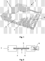
- the loudspeaker 1 comprises a multi-layer panel consisting essentially of three or more layers of thin, flexible material, and more particularly an electrically insulating middle layer 2 sandwiched between top and bottom electrically conducting outer layers 3 and 4.
- the middle layer 2 is a polymer membrane optionally having a profiled surface having circular pits (not shown) in contact with the top outer layer 3.
- the top outer layer 3 comprises a thin polymer membrane provided with a layer of metallisation applied to its outer surface by a known metallisation process, such as vapour deposition. Although the top outer layer 3 is shown as a separate layer in Figure 1 , this outer layer 3 may be replaced by a layer of metallisation applied to the back surface of the middle layer 2 by a conventional metallisation process.
- the top outer layer 3 may be made from, for example, domestic aluminium foil, metallised foil, paper coated with a layer of conducting paint or copper foil.
- a thin polymer membrane provided with a layer of metalisation on its outer surface is preferred. This has a very low mass and is therefore better able to couple its motion to the air generating the sound.
- the display itself can be used as a layer in the loudspeaker.
- the middle layer 2 may be made from, for example, paper, greaseproof paper, cloth or plastic. However it would appear that the output is optimised if a polymer membrane is used. Usually this middle layer 2 does not require any kind of profiling in order to optimise the audio reproduction. However profiling of this layer is not excluded. This layer may be permanently electrostatically charged to eliminate or minimise the applied DC bias.
- the bottom outer layer 4 is a thin porous conducting membrane comprising a regular matrix of holes extending through the layer 4.
- the use of a porous bottom layer 4 helps facilitate the movement of the membranes of the loudspeaker as it ensures the other membranes are not constrained against any forward movement by a pressure imbalance, in the form of a partial vacuum behind the insulating middle layer 2.
- the porous bottom layer 4 may, by way of example, be formed from an interwoven mesh of aluminium wire of 0.1 mm diameter comprising parallel strands of wire extending in one direction woven together with strands of wire extending in a perpendicular direction using a twill weave pattern (a twill weave is formed by individual strands going over two strands and then under two strands).
- the size of the aperture between the wires is typically 0.11 mm and the number of wires used per inch is typically 120.
- the percentage of open area, governed by the gauge of the wire, is approximately 27%.
- a d.c. power supply 7 is provided for supplying a d.c. potential, of, for example, 300V across the top and bottom conducting layers 3 and 4.
- a signal generator 8 is connected across the top and bottom conducting layers 3 and 4 for applying an alternating signal to drive the loudspeaker 1.
- capacitative decoupling may be used to separate the d.c. and a.c. voltages.
- the d.c. potential causes the top outer layer 3 to be drawn onto the bottom layer 4.
- the audio (AC) signal is applied by the signal generator 8 across the outer layers 3 and 4
- the electrostatic forces acting between the layers 3 and 2 are caused to vary and this in turn causes the layers to vibrate and the air immediately above it generates the required sound.
- the construction of the speaker is also key to the quality of the reproduced sound.
- both conducting layers will vibrate as a rigid piston across the entire area to produce sound.
- the application of the DC bias causes the top layer to be drawn onto the middle layer which in turn is drawn onto the bottom layer.
- the electrostatic forces acting between the layers are caused to vary and this in turn causes the layers to vibrate.
- the layers move as a whole in operation it is important for the layers to be uniform across their surfaces. Any slight deviation caused, for example, by a crease or crinkle will alter the force felt by the layers at that point, thus altering the motion and leading to distortion in the reproduced audio signal.
- Such a loudspeaker does not require the large voltages required by conventional electrostatic loudspeakers since the electrostatic field is large because the separation of the electrodes is small.
- a reasonably small voltage (for example 36V) may therefore be used to produce such an electric field, although higher voltages of 300V may be required in some cases to generate larger acoustic amplitudes.
- the first outer layer 3 may be profiled instead of (or in addition to) the middle layer 2.
- the d.c. supply may be eliminated completely by using a permanently charged material for the membrane and/or the middle layer 2.
- the middle layer is formed by a sheet of a thin porous material, such as paper or tissue. Use of a porous middle layer 2 helps the movement of the top layer in that it is not constrained against movement in the forward direction (i.e. away from the middle layer) by a pressure imbalance, in the form of a partial vacuum behind the layer. This is particularly so for lower acoustic frequencies which require greater displacements, and would generate a greater partial vacuum.
- the compressibility of a material such as paper or tissue provides a resilient force which complements or replaces the drumskin tensional forces described previously.
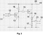
- Figure 3 shows a drive circuit, which may be used to drive such a loudspeaker, having an audio input 10 for receiving an audio input signal to be amplified by a preamplifier 12.
- the signal is then applied to a pair of MOSFET's 13, 14 which are biased by resistors 18, 19 and supplied with power from a voltage supply rail 20, which is typically connected to a +200V supply.
- the output 15 from this circuit is connected to drive the loudspeakers.
- resistors 16, 17, 21 the output can be adjusted to have a suitable d.c. bias voltage, as well as an a.c. signal voltage.
- the loudspeakers in accordance with the invention described above are not only very thin, i.e. less than 0.5 mm, but are also flexible allowing them to be easily contoured.
- Such contouring can either be used to fit the loudspeaker to suit its environment, for example to fit within a room with curved walls or within a curved computer casing or screen, or to modify the emitted acoustic field, for example by being made concave to focus the sound or convex to spread the sound.
- Such a loudspeaker can be adapted very easily to have a frequency bandwidth in air well above the audible range, up to 2 MHz. Whilst such loudspeaker may have poorer low-frequency response, this can be improved by careful design of the loudspeaker components.
- the loudspeakers are inherently efficient at generating sound from electrical signals and can consequently be considered to be low power. This is of particular advantage where power consumption is at a premium, for example with battery powered devices such as notebook computers, novelty Christmas cards, or even novel audio advertising posters. There are advantages in having high electrical efficiency loudspeakers with very-high power public address systems, such as are heard at rock concerts.
- the ability to produce large areas of loudspeaker at relatively low cost using such a construction also offers novel applications for home audio systems, allowing loudspeakers to be hung as wallpaper on walls or ceilings.
- large area sound sources have potential advantages for the sound field of such audio systems.
- a permanently charged polymer film is attached to the rear of the loudspeaker, the resulting electrostatic forces can be used to stick the loudspeaker to the wall, enabling the loudspeaker to be rolled up and moved to a new location when required.
- a further application of the invention is to noise cancellation systems in which ambient noise is cancelled by the generation of anti-noise by a loudspeaker component in accordance with the invention.
Landscapes
- Physics & Mathematics (AREA)
- Engineering & Computer Science (AREA)
- Acoustics & Sound (AREA)
- Signal Processing (AREA)
- Piezo-Electric Transducers For Audible Bands (AREA)
- Electrostatic, Electromagnetic, Magneto- Strictive, And Variable-Resistance Transducers (AREA)
Applications Claiming Priority (2)
| Application Number | Priority Date | Filing Date | Title |
|---|---|---|---|
| GBGB0600014.5A GB0600014D0 (en) | 2006-01-03 | 2006-01-03 | Electrostatic loudspeakers |
| PCT/GB2006/050468 WO2007077438A1 (en) | 2006-01-03 | 2006-12-19 | Electrostatic loudspeakers |
Publications (2)
| Publication Number | Publication Date |
|---|---|
| EP1972178A1 EP1972178A1 (en) | 2008-09-24 |
| EP1972178B1 true EP1972178B1 (en) | 2019-06-19 |
Family
ID=35841433
Family Applications (1)
| Application Number | Title | Priority Date | Filing Date |
|---|---|---|---|
| EP06820693.7A Active EP1972178B1 (en) | 2006-01-03 | 2006-12-19 | Electrostatic loudspeakers |
Country Status (6)
| Country | Link |
|---|---|
| US (1) | US8416973B2 (enExample) |
| EP (1) | EP1972178B1 (enExample) |
| JP (1) | JP5075836B2 (enExample) |
| CN (1) | CN101395957B (enExample) |
| GB (1) | GB0600014D0 (enExample) |
| WO (1) | WO2007077438A1 (enExample) |
Families Citing this family (24)
| Publication number | Priority date | Publication date | Assignee | Title |
|---|---|---|---|---|
| US8625824B2 (en) | 2007-09-04 | 2014-01-07 | Industrial Technology Research Institute | Flat speaker unit and speaker device therewith |
| TWI330500B (en) * | 2007-09-04 | 2010-09-11 | Ind Tech Res Inst | Speaker structure |
| CN101494810B (zh) * | 2008-01-22 | 2013-02-06 | 普诚科技股份有限公司 | 声音播放装置及其方法 |
| EP2312868A3 (en) * | 2009-09-30 | 2014-01-01 | Yamaha Corporation | Electrostatic speaker |
| US8831253B2 (en) | 2009-10-22 | 2014-09-09 | Industrial Technology Research Institute | Electroacoustic apparatus with optical energy conversion function |
| TW201204062A (en) * | 2010-07-15 | 2012-01-16 | Taiwan Electrets Electronics Co Ltd | Electrostatic speaker and manufacturing method thereof and conducting plate of the speaker |
| GB2490930A (en) | 2011-05-19 | 2012-11-21 | Warwick Audio Technologies Ltd | A switching amplifier arrangement providing both signal drive and a high bias voltage for an electrostatic loudspeaker |
| GB2490931A (en) | 2011-05-19 | 2012-11-21 | Warwick Audio Technologies Ltd | Electrostatic acoustic transducer |
| US9417213B1 (en) * | 2011-07-11 | 2016-08-16 | The Boeing Company | Non-destructive evaluation system for aircraft |
| RU2547897C2 (ru) * | 2013-07-26 | 2015-04-10 | Открытое акционерное общество "Военно-промышленная корпорация "Научно-производственное объединение машиностроения" | Электростатический громкоговоритель с широкой диаграммой направленности |
| DE102013225046A1 (de) * | 2013-12-05 | 2015-06-11 | Lufthansa Technik Ag | Flugzeugtriebwerk, Passagierflugzeug, Verfahren zur aktiven Geräuschminderung und Verfahren zum Nachrüsten eines Gasturbinen-Flugzeugtriebwerks |
| GB2522931A (en) | 2014-02-11 | 2015-08-12 | Warwick Audio Technologies Ltd | Improved electrostatic transducer |
| GB2522932A (en) | 2014-02-11 | 2015-08-12 | Warwick Audio Technologies Ltd | Improved electrostatic transducer |
| KR102369124B1 (ko) | 2014-12-26 | 2022-03-03 | 삼성디스플레이 주식회사 | 영상 표시 장치 |
| US9725047B2 (en) * | 2015-06-22 | 2017-08-08 | Ford Global Technologies, Llc | Loudspeaker arrangement in a vehicle |
| CN105228065A (zh) * | 2015-11-02 | 2016-01-06 | 李崇 | 具有良好音质效果的薄膜扬声器 |
| CN106454667B (zh) * | 2016-08-24 | 2022-04-22 | 深圳市炜鼎科技有限公司 | 静电扬声器系统 |
| KR102691540B1 (ko) | 2016-11-04 | 2024-08-05 | 삼성전자주식회사 | 평면형 마그넷 스피커 |
| JP7410935B2 (ja) | 2018-05-24 | 2024-01-10 | ザ リサーチ ファウンデーション フォー ザ ステイト ユニバーシティー オブ ニューヨーク | 容量性センサ |
| US11153690B2 (en) * | 2018-08-22 | 2021-10-19 | Dsp Group Ltd. | Electrostatic speaker and a method for generating acoustic signals |
| CN110087175A (zh) * | 2019-04-17 | 2019-08-02 | 海菲曼(天津)科技有限公司 | 一种静电扬声器定子极板及静电扬声器 |
| GB201906425D0 (en) | 2019-05-07 | 2019-06-19 | Warwick Acoustics Ltd | Electrostatic transducer and diaphragm |
| WO2024257668A1 (ja) * | 2023-06-14 | 2024-12-19 | 旭化成株式会社 | 可撓性薄型スピーカーを含む自動車内装材 |
| TWI870019B (zh) * | 2023-09-13 | 2025-01-11 | 英業達股份有限公司 | 將靜電喇叭設置在筆記型電腦的方法 |
Citations (2)
| Publication number | Priority date | Publication date | Assignee | Title |
|---|---|---|---|---|
| US1764008A (en) * | 1928-10-24 | 1930-06-17 | United Reproducers Patents Cor | Push-pull electrostatic sound reproducer |
| GB2245451A (en) * | 1990-04-13 | 1992-01-02 | Sansui Electric Co | Diaphragm for speaker |
Family Cites Families (13)
| Publication number | Priority date | Publication date | Assignee | Title |
|---|---|---|---|---|
| US1759809A (en) * | 1929-04-03 | 1930-05-20 | Ephraim Banning | Acoustic condenser |
| DE2330800C3 (de) * | 1973-06-16 | 1981-10-01 | Sennheiser Electronic Kg, 3002 Wedemark | Elektroakustischer Wandler nach dem elektrostatischen Prinzip und Verfahren zu dessen Herstellung |
| JPS5419172B2 (enExample) | 1973-07-23 | 1979-07-13 | ||
| US4515997A (en) * | 1982-09-23 | 1985-05-07 | Stinger Jr Walter E | Direct digital loudspeaker |
| US4533794A (en) * | 1983-05-23 | 1985-08-06 | Beveridge Harold N | Electrode for electrostatic transducer |
| AT386505B (de) * | 1986-12-09 | 1988-09-12 | Akg Akustische Kino Geraete | Elektroakustischer oder elektromechanischer wandler nach dem elektrostatischen umwandlungsprinzip |
| JP3246685B2 (ja) * | 1993-02-18 | 2002-01-15 | フオスター電機株式会社 | 電気音響変換器 |
| JP3502524B2 (ja) * | 1997-02-19 | 2004-03-02 | 日本碍子株式会社 | トランスデューサアレイ |
| USRE40860E1 (en) | 2000-09-02 | 2009-07-21 | University Of Warwick | Electrostatic audio loudspeakers |
| JP3662505B2 (ja) * | 2001-03-16 | 2005-06-22 | シャープ株式会社 | 透明スピーカ及びマイク一体型時刻表示装置 |
| DE10300063A1 (de) | 2003-01-03 | 2004-07-22 | W.L. Gore & Associates Gmbh | Membran für akustische Wandler |
| US6943448B2 (en) * | 2003-01-23 | 2005-09-13 | Akustica, Inc. | Multi-metal layer MEMS structure and process for making the same |
| JP3873990B2 (ja) * | 2004-06-11 | 2007-01-31 | セイコーエプソン株式会社 | 超音波トランスデューサ及びこれを用いた超音波スピーカ |
-
2006
- 2006-01-03 GB GBGB0600014.5A patent/GB0600014D0/en not_active Ceased
- 2006-12-19 US US12/159,882 patent/US8416973B2/en active Active
- 2006-12-19 WO PCT/GB2006/050468 patent/WO2007077438A1/en not_active Ceased
- 2006-12-19 EP EP06820693.7A patent/EP1972178B1/en active Active
- 2006-12-19 JP JP2008549054A patent/JP5075836B2/ja active Active
- 2006-12-19 CN CN200680053688.3A patent/CN101395957B/zh active Active
Patent Citations (2)
| Publication number | Priority date | Publication date | Assignee | Title |
|---|---|---|---|---|
| US1764008A (en) * | 1928-10-24 | 1930-06-17 | United Reproducers Patents Cor | Push-pull electrostatic sound reproducer |
| GB2245451A (en) * | 1990-04-13 | 1992-01-02 | Sansui Electric Co | Diaphragm for speaker |
Also Published As
| Publication number | Publication date |
|---|---|
| GB0600014D0 (en) | 2006-02-08 |
| JP2009522899A (ja) | 2009-06-11 |
| JP5075836B2 (ja) | 2012-11-21 |
| US20090016552A1 (en) | 2009-01-15 |
| EP1972178A1 (en) | 2008-09-24 |
| WO2007077438A1 (en) | 2007-07-12 |
| CN101395957B (zh) | 2013-03-20 |
| US8416973B2 (en) | 2013-04-09 |
| CN101395957A (zh) | 2009-03-25 |
Similar Documents
| Publication | Publication Date | Title |
|---|---|---|
| EP1972178B1 (en) | Electrostatic loudspeakers | |
| JP2009522899A5 (enExample) | ||
| USRE40860E1 (en) | Electrostatic audio loudspeakers | |
| CN101656904B (zh) | 扬声系统 | |
| US4246448A (en) | Electromechanical transducer | |
| US3345469A (en) | Electrostatic loudspeakers | |
| US6188772B1 (en) | Electrostatic speaker with foam stator | |
| KR100574711B1 (ko) | 스피커 장치 및 음파 에너지 전파 방법 | |
| CN1997243A (zh) | 可挠式扬声器及其制法 | |
| CN102082987B (zh) | 音响致动装置及音响致动装置系统 | |
| JP3502524B2 (ja) | トランスデューサアレイ | |
| CN110505557A (zh) | 一种扬声器及终端设备 | |
| US6819769B1 (en) | Electrolytic loudspeaker assembly | |
| Klug et al. | Design, fabrication, and customized driving of dielectric loudspeaker arrays | |
| EP3105941B1 (en) | Improved electrostatic transducer | |
| JP2002535945A (ja) | 複合電解式スピーカ集成体 | |
| JP6495866B2 (ja) | スピーカーユニット | |
| JP4862700B2 (ja) | 静電型スピーカ | |
| Ko et al. | Study and application of free-form electret actuators | |
| KR102855978B1 (ko) | 장력조절을 통한 멤브레인 동특성 변경이 가능한 음향발생장치 | |
| US8085957B2 (en) | Method for converting electric signals into acoustic oscillations and an electric gas-kinetic transducer | |
| RU2287913C2 (ru) | Электростатический акустический преобразователь | |
| JP2007274342A (ja) | 静電型スピーカ | |
| CN101778326A (zh) | 柔性冷光电声致动器及使用该电声致动器的电子装置 | |
| JP2013051665A (ja) | 電気音響変換器および電気音響変換器用カバー |
Legal Events
| Date | Code | Title | Description |
|---|---|---|---|
| PUAI | Public reference made under article 153(3) epc to a published international application that has entered the european phase |
Free format text: ORIGINAL CODE: 0009012 |
|
| 17P | Request for examination filed |
Effective date: 20080724 |
|
| AK | Designated contracting states |
Kind code of ref document: A1 Designated state(s): AT BE BG CH CY CZ DE DK EE ES FI FR GB GR HU IE IS IT LI LT LU LV MC NL PL PT RO SE SI SK TR |
|
| 17Q | First examination report despatched |
Effective date: 20120201 |
|
| DAX | Request for extension of the european patent (deleted) | ||
| RAP1 | Party data changed (applicant data changed or rights of an application transferred) |
Owner name: WARWICK AUDIO TECHNOLOGIES LIMITED |
|
| STAA | Information on the status of an ep patent application or granted ep patent |
Free format text: STATUS: EXAMINATION IS IN PROGRESS |
|
| GRAP | Despatch of communication of intention to grant a patent |
Free format text: ORIGINAL CODE: EPIDOSNIGR1 |
|
| STAA | Information on the status of an ep patent application or granted ep patent |
Free format text: STATUS: GRANT OF PATENT IS INTENDED |
|
| INTG | Intention to grant announced |
Effective date: 20190103 |
|
| RAP1 | Party data changed (applicant data changed or rights of an application transferred) |
Owner name: WARWICK ACOUSTICS LIMITED |
|
| GRAS | Grant fee paid |
Free format text: ORIGINAL CODE: EPIDOSNIGR3 |
|
| GRAA | (expected) grant |
Free format text: ORIGINAL CODE: 0009210 |
|
| STAA | Information on the status of an ep patent application or granted ep patent |
Free format text: STATUS: THE PATENT HAS BEEN GRANTED |
|
| AK | Designated contracting states |
Kind code of ref document: B1 Designated state(s): AT BE BG CH CY CZ DE DK EE ES FI FR GB GR HU IE IS IT LI LT LU LV MC NL PL PT RO SE SI SK TR |
|
| REG | Reference to a national code |
Ref country code: GB Ref legal event code: FG4D |
|
| REG | Reference to a national code |
Ref country code: CH Ref legal event code: EP |
|
| REG | Reference to a national code |
Ref country code: IE Ref legal event code: FG4D |
|
| REG | Reference to a national code |
Ref country code: DE Ref legal event code: R096 Ref document number: 602006058181 Country of ref document: DE |
|
| REG | Reference to a national code |
Ref country code: AT Ref legal event code: REF Ref document number: 1147041 Country of ref document: AT Kind code of ref document: T Effective date: 20190715 |
|
| REG | Reference to a national code |
Ref country code: NL Ref legal event code: MP Effective date: 20190619 |
|
| PG25 | Lapsed in a contracting state [announced via postgrant information from national office to epo] |
Ref country code: FI Free format text: LAPSE BECAUSE OF FAILURE TO SUBMIT A TRANSLATION OF THE DESCRIPTION OR TO PAY THE FEE WITHIN THE PRESCRIBED TIME-LIMIT Effective date: 20190619 Ref country code: LT Free format text: LAPSE BECAUSE OF FAILURE TO SUBMIT A TRANSLATION OF THE DESCRIPTION OR TO PAY THE FEE WITHIN THE PRESCRIBED TIME-LIMIT Effective date: 20190619 Ref country code: SE Free format text: LAPSE BECAUSE OF FAILURE TO SUBMIT A TRANSLATION OF THE DESCRIPTION OR TO PAY THE FEE WITHIN THE PRESCRIBED TIME-LIMIT Effective date: 20190619 |
|
| REG | Reference to a national code |
Ref country code: LT Ref legal event code: MG4D |
|
| PG25 | Lapsed in a contracting state [announced via postgrant information from national office to epo] |
Ref country code: GR Free format text: LAPSE BECAUSE OF FAILURE TO SUBMIT A TRANSLATION OF THE DESCRIPTION OR TO PAY THE FEE WITHIN THE PRESCRIBED TIME-LIMIT Effective date: 20190920 Ref country code: BG Free format text: LAPSE BECAUSE OF FAILURE TO SUBMIT A TRANSLATION OF THE DESCRIPTION OR TO PAY THE FEE WITHIN THE PRESCRIBED TIME-LIMIT Effective date: 20190919 Ref country code: LV Free format text: LAPSE BECAUSE OF FAILURE TO SUBMIT A TRANSLATION OF THE DESCRIPTION OR TO PAY THE FEE WITHIN THE PRESCRIBED TIME-LIMIT Effective date: 20190619 |
|
| REG | Reference to a national code |
Ref country code: AT Ref legal event code: MK05 Ref document number: 1147041 Country of ref document: AT Kind code of ref document: T Effective date: 20190619 |
|
| PG25 | Lapsed in a contracting state [announced via postgrant information from national office to epo] |
Ref country code: SK Free format text: LAPSE BECAUSE OF FAILURE TO SUBMIT A TRANSLATION OF THE DESCRIPTION OR TO PAY THE FEE WITHIN THE PRESCRIBED TIME-LIMIT Effective date: 20190619 Ref country code: EE Free format text: LAPSE BECAUSE OF FAILURE TO SUBMIT A TRANSLATION OF THE DESCRIPTION OR TO PAY THE FEE WITHIN THE PRESCRIBED TIME-LIMIT Effective date: 20190619 Ref country code: PT Free format text: LAPSE BECAUSE OF FAILURE TO SUBMIT A TRANSLATION OF THE DESCRIPTION OR TO PAY THE FEE WITHIN THE PRESCRIBED TIME-LIMIT Effective date: 20191021 Ref country code: AT Free format text: LAPSE BECAUSE OF FAILURE TO SUBMIT A TRANSLATION OF THE DESCRIPTION OR TO PAY THE FEE WITHIN THE PRESCRIBED TIME-LIMIT Effective date: 20190619 Ref country code: NL Free format text: LAPSE BECAUSE OF FAILURE TO SUBMIT A TRANSLATION OF THE DESCRIPTION OR TO PAY THE FEE WITHIN THE PRESCRIBED TIME-LIMIT Effective date: 20190619 Ref country code: RO Free format text: LAPSE BECAUSE OF FAILURE TO SUBMIT A TRANSLATION OF THE DESCRIPTION OR TO PAY THE FEE WITHIN THE PRESCRIBED TIME-LIMIT Effective date: 20190619 Ref country code: CZ Free format text: LAPSE BECAUSE OF FAILURE TO SUBMIT A TRANSLATION OF THE DESCRIPTION OR TO PAY THE FEE WITHIN THE PRESCRIBED TIME-LIMIT Effective date: 20190619 |
|
| PG25 | Lapsed in a contracting state [announced via postgrant information from national office to epo] |
Ref country code: IT Free format text: LAPSE BECAUSE OF FAILURE TO SUBMIT A TRANSLATION OF THE DESCRIPTION OR TO PAY THE FEE WITHIN THE PRESCRIBED TIME-LIMIT Effective date: 20190619 Ref country code: ES Free format text: LAPSE BECAUSE OF FAILURE TO SUBMIT A TRANSLATION OF THE DESCRIPTION OR TO PAY THE FEE WITHIN THE PRESCRIBED TIME-LIMIT Effective date: 20190619 Ref country code: IS Free format text: LAPSE BECAUSE OF FAILURE TO SUBMIT A TRANSLATION OF THE DESCRIPTION OR TO PAY THE FEE WITHIN THE PRESCRIBED TIME-LIMIT Effective date: 20191019 |
|
| PG25 | Lapsed in a contracting state [announced via postgrant information from national office to epo] |
Ref country code: TR Free format text: LAPSE BECAUSE OF FAILURE TO SUBMIT A TRANSLATION OF THE DESCRIPTION OR TO PAY THE FEE WITHIN THE PRESCRIBED TIME-LIMIT Effective date: 20190619 |
|
| PG25 | Lapsed in a contracting state [announced via postgrant information from national office to epo] |
Ref country code: PL Free format text: LAPSE BECAUSE OF FAILURE TO SUBMIT A TRANSLATION OF THE DESCRIPTION OR TO PAY THE FEE WITHIN THE PRESCRIBED TIME-LIMIT Effective date: 20190619 Ref country code: DK Free format text: LAPSE BECAUSE OF FAILURE TO SUBMIT A TRANSLATION OF THE DESCRIPTION OR TO PAY THE FEE WITHIN THE PRESCRIBED TIME-LIMIT Effective date: 20190619 |
|
| PG25 | Lapsed in a contracting state [announced via postgrant information from national office to epo] |
Ref country code: IS Free format text: LAPSE BECAUSE OF FAILURE TO SUBMIT A TRANSLATION OF THE DESCRIPTION OR TO PAY THE FEE WITHIN THE PRESCRIBED TIME-LIMIT Effective date: 20200224 |
|
| REG | Reference to a national code |
Ref country code: DE Ref legal event code: R097 Ref document number: 602006058181 Country of ref document: DE |
|
| PLBE | No opposition filed within time limit |
Free format text: ORIGINAL CODE: 0009261 |
|
| STAA | Information on the status of an ep patent application or granted ep patent |
Free format text: STATUS: NO OPPOSITION FILED WITHIN TIME LIMIT |
|
| PG2D | Information on lapse in contracting state deleted |
Ref country code: IS |
|
| REG | Reference to a national code |
Ref country code: CH Ref legal event code: PL |
|
| 26N | No opposition filed |
Effective date: 20200603 |
|
| REG | Reference to a national code |
Ref country code: BE Ref legal event code: MM Effective date: 20191231 |
|
| PG25 | Lapsed in a contracting state [announced via postgrant information from national office to epo] |
Ref country code: MC Free format text: LAPSE BECAUSE OF FAILURE TO SUBMIT A TRANSLATION OF THE DESCRIPTION OR TO PAY THE FEE WITHIN THE PRESCRIBED TIME-LIMIT Effective date: 20190619 Ref country code: SI Free format text: LAPSE BECAUSE OF FAILURE TO SUBMIT A TRANSLATION OF THE DESCRIPTION OR TO PAY THE FEE WITHIN THE PRESCRIBED TIME-LIMIT Effective date: 20190619 |
|
| PG25 | Lapsed in a contracting state [announced via postgrant information from national office to epo] |
Ref country code: LU Free format text: LAPSE BECAUSE OF NON-PAYMENT OF DUE FEES Effective date: 20191219 Ref country code: IE Free format text: LAPSE BECAUSE OF NON-PAYMENT OF DUE FEES Effective date: 20191219 |
|
| PG25 | Lapsed in a contracting state [announced via postgrant information from national office to epo] |
Ref country code: BE Free format text: LAPSE BECAUSE OF NON-PAYMENT OF DUE FEES Effective date: 20191231 Ref country code: CH Free format text: LAPSE BECAUSE OF NON-PAYMENT OF DUE FEES Effective date: 20191231 Ref country code: LI Free format text: LAPSE BECAUSE OF NON-PAYMENT OF DUE FEES Effective date: 20191231 |
|
| PG25 | Lapsed in a contracting state [announced via postgrant information from national office to epo] |
Ref country code: CY Free format text: LAPSE BECAUSE OF FAILURE TO SUBMIT A TRANSLATION OF THE DESCRIPTION OR TO PAY THE FEE WITHIN THE PRESCRIBED TIME-LIMIT Effective date: 20190619 |
|
| PG25 | Lapsed in a contracting state [announced via postgrant information from national office to epo] |
Ref country code: HU Free format text: LAPSE BECAUSE OF FAILURE TO SUBMIT A TRANSLATION OF THE DESCRIPTION OR TO PAY THE FEE WITHIN THE PRESCRIBED TIME-LIMIT; INVALID AB INITIO Effective date: 20061219 |
|
| PGFP | Annual fee paid to national office [announced via postgrant information from national office to epo] |
Ref country code: DE Payment date: 20241210 Year of fee payment: 19 |
|
| PGFP | Annual fee paid to national office [announced via postgrant information from national office to epo] |
Ref country code: GB Payment date: 20241010 Year of fee payment: 19 |
|
| PGFP | Annual fee paid to national office [announced via postgrant information from national office to epo] |
Ref country code: FR Payment date: 20241223 Year of fee payment: 19 |