EP1970699A2 - Vorrichtung und Verfahren zur Erfassung von Verunreinigungen auf einem transparenten Substrat - Google Patents
Vorrichtung und Verfahren zur Erfassung von Verunreinigungen auf einem transparenten Substrat Download PDFInfo
- Publication number
- EP1970699A2 EP1970699A2 EP08102500A EP08102500A EP1970699A2 EP 1970699 A2 EP1970699 A2 EP 1970699A2 EP 08102500 A EP08102500 A EP 08102500A EP 08102500 A EP08102500 A EP 08102500A EP 1970699 A2 EP1970699 A2 EP 1970699A2
- Authority
- EP
- European Patent Office
- Prior art keywords
- substrate
- source
- line
- hollow cylindrical
- shaped
- Prior art date
- Legal status (The legal status is an assumption and is not a legal conclusion. Google has not performed a legal analysis and makes no representation as to the accuracy of the status listed.)
- Granted
Links
- 239000000758 substrate Substances 0.000 title claims abstract description 93
- 239000012535 impurity Substances 0.000 title claims abstract description 20
- 238000000034 method Methods 0.000 title claims abstract description 16
- 239000011521 glass Substances 0.000 claims description 37
- 230000035622 drinking Effects 0.000 claims description 25
- 230000005670 electromagnetic radiation Effects 0.000 claims description 10
- 230000005855 radiation Effects 0.000 claims description 7
- 238000001514 detection method Methods 0.000 claims description 6
- 238000011109 contamination Methods 0.000 claims description 2
- 238000005286 illumination Methods 0.000 abstract description 22
- 230000004308 accommodation Effects 0.000 abstract 1
- 238000004851 dishwashing Methods 0.000 description 13
- 238000005259 measurement Methods 0.000 description 10
- 230000005540 biological transmission Effects 0.000 description 8
- 239000003599 detergent Substances 0.000 description 7
- 238000011156 evaluation Methods 0.000 description 4
- 239000003795 chemical substances by application Substances 0.000 description 3
- 238000004140 cleaning Methods 0.000 description 2
- 238000013461 design Methods 0.000 description 2
- 230000003287 optical effect Effects 0.000 description 2
- 239000004094 surface-active agent Substances 0.000 description 2
- XLYOFNOQVPJJNP-UHFFFAOYSA-N water Substances O XLYOFNOQVPJJNP-UHFFFAOYSA-N 0.000 description 2
- 241000722921 Tulipa gesneriana Species 0.000 description 1
- 238000010521 absorption reaction Methods 0.000 description 1
- 238000011511 automated evaluation Methods 0.000 description 1
- 235000013405 beer Nutrition 0.000 description 1
- 238000000576 coating method Methods 0.000 description 1
- 239000000356 contaminant Substances 0.000 description 1
- 238000011161 development Methods 0.000 description 1
- 230000000694 effects Effects 0.000 description 1
- 230000007257 malfunction Effects 0.000 description 1
- 239000002184 metal Substances 0.000 description 1
- 229920000642 polymer Polymers 0.000 description 1
- 229910052573 porcelain Inorganic materials 0.000 description 1
- 238000012545 processing Methods 0.000 description 1
- 238000011158 quantitative evaluation Methods 0.000 description 1
- 239000002689 soil Substances 0.000 description 1
- 239000007787 solid Substances 0.000 description 1
- 238000012360 testing method Methods 0.000 description 1
- 230000000007 visual effect Effects 0.000 description 1
- 238000005406 washing Methods 0.000 description 1
Images
Classifications
-
- G—PHYSICS
- G01—MEASURING; TESTING
- G01N—INVESTIGATING OR ANALYSING MATERIALS BY DETERMINING THEIR CHEMICAL OR PHYSICAL PROPERTIES
- G01N21/00—Investigating or analysing materials by the use of optical means, i.e. using sub-millimetre waves, infrared, visible or ultraviolet light
- G01N21/84—Systems specially adapted for particular applications
- G01N21/88—Investigating the presence of flaws or contamination
- G01N21/90—Investigating the presence of flaws or contamination in a container or its contents
- G01N21/9018—Dirt detection in containers
-
- G—PHYSICS
- G01—MEASURING; TESTING
- G01N—INVESTIGATING OR ANALYSING MATERIALS BY DETERMINING THEIR CHEMICAL OR PHYSICAL PROPERTIES
- G01N21/00—Investigating or analysing materials by the use of optical means, i.e. using sub-millimetre waves, infrared, visible or ultraviolet light
- G01N21/84—Systems specially adapted for particular applications
- G01N21/88—Investigating the presence of flaws or contamination
- G01N21/90—Investigating the presence of flaws or contamination in a container or its contents
- G01N21/909—Investigating the presence of flaws or contamination in a container or its contents in opaque containers or opaque container parts, e.g. cans, tins, caps, labels
-
- G—PHYSICS
- G01—MEASURING; TESTING
- G01N—INVESTIGATING OR ANALYSING MATERIALS BY DETERMINING THEIR CHEMICAL OR PHYSICAL PROPERTIES
- G01N21/00—Investigating or analysing materials by the use of optical means, i.e. using sub-millimetre waves, infrared, visible or ultraviolet light
- G01N21/84—Systems specially adapted for particular applications
- G01N21/88—Investigating the presence of flaws or contamination
- G01N21/8806—Specially adapted optical and illumination features
- G01N2021/8822—Dark field detection
-
- G—PHYSICS
- G01—MEASURING; TESTING
- G01N—INVESTIGATING OR ANALYSING MATERIALS BY DETERMINING THEIR CHEMICAL OR PHYSICAL PROPERTIES
- G01N21/00—Investigating or analysing materials by the use of optical means, i.e. using sub-millimetre waves, infrared, visible or ultraviolet light
- G01N21/84—Systems specially adapted for particular applications
- G01N21/8422—Investigating thin films, e.g. matrix isolation method
Definitions
- the present invention relates to a device for detecting impurities on an at least partially transparent substrate and to a corresponding method.
- Modern dishwashing detergents are multifunctional products which, in addition to cleaning soiled dishes in a dishwasher, also perform rinsing and water softening through the addition of special surfactants and polymers suitable for this purpose.
- the rinsing performance is crucial.
- the surfactants present in the dishwashing detergents are primarily responsible. These should develop their full effect only in the final rinse cycle despite the addition to the dishwashing detergent already in the main cleaning cycle. If malfunctions occur in the course of machine dishwashing or if the dishwashing agent used does not meet the requirements set out, small stains, referred to as spotting, and film-like coatings, referred to as filming, are visible on the dishes after completion of the rinsing process.
- EP 1 635 167 A1 is a method for the quantitative measurement of deposits on solid surfaces known, wherein the surface to be measured is formed as a plump sample, for example in the form of a rectangular or round plate, and with visible light a light source is irradiated, wherein the light reflected and / or scattered by the specimen is received by a camera and the resulting image is computer-aided quantitatively evaluated.
- this prior art document discloses both measurements in reflection and in transmission.
- planar elements are used both for illuminating the substrate and for detecting the radiation reflected or scattered by the substrate.
- the automated evaluation methods known from the prior art are based on the optical detection of the reflection and scattering processes on spotting and filming on test substrates after the automatic dishwashing process.
- Only flat substrates are used as models for dishes made of metal, porcelain and glass.
- these plan models are not able to adequately reflect the actual washing performance of the dishwashing detergents, in particular for glasses.
- Especially the rinsing of drinking glasses is a serious problem in machine dishwashing, which is caused inter alia by the curvature of the surfaces to be cleaned due to the hollow cylindrical basic shape of drinking glasses.
- the planar substrates used in the prior art are comparatively easy to measure, they represent an excessively simplistic model with regard to drinking glasses.
- a device for detecting impurities on an at least partially transparent substrate with a source and a line-shaped detector array for electromagnetic radiation and with a substrate holder for a curved substrate, which is arranged so that a received therein curved substrate extends at least in sections between the source and the detector array is provided.
- the source of electromagnetic radiation is a line-shaped source.
- linear is understood to mean a planar expansion of the source and of the detector arrangement, which is significantly greater in a first direction than in a second direction perpendicular to the first direction.
- An example of a line-shaped source according to the invention is an arrangement of a plurality of radiation sources arranged side by side, preferably in a row, preferably light-emitting diodes.
- An example of a line detector array according to the present invention is a CCD or CMOS line scan camera.
- the line-shaped design of source and detector arrangement makes it possible to detect impurities on a curved substrate, without having to take into account artifacts due to the curvature of the substrate separately numerically.
- the line-shaped detector arrangement extends substantially parallel to the axis of a substantially hollow-cylindrical substrate, then only one, ideally very small, angular section of the surface of the curved substrate is detected whose curvature is then negligibly small for the considered area, so that in this Range from the detection of a nearly planar substrate can be assumed.
- a hollow-cylindrical substrate is a substrate with an axis of symmetry which has a curved surface at least around the axis of symmetry, such as e.g. a drinking glass.
- a hollow cylindrical substrate may also have a curvature in a second direction, e.g. in a beer tulip, have.
- the apparatus comprises a substrate holder which is arranged so that a substrate received therein extends between the light source and the detector array, i. a measurement is made in transmission through the substrate.
- An embodiment of the device according to the invention is particularly suitable for the detection of contaminants on drinking glasses, wherein the substrate holder is designed so that it allows the inclusion of a substantially hollow cylindrical substrate, wherein the source or the line-shaped detector arrangement in the operation of the device in the hollow cylindrical substrate located. In this way, only a very small section of the hollow cylinder is detected by means of the line-shaped detector arrangement in transmission.
- an embodiment of the invention is expedient in which the substrate holder has an axis of rotation and is rotatable so that a substantially hollow cylindrical substrate received in the substrate holder is substantially concentric about the line-shaped substrate Source or the line-shaped detector array is rotatable around.
- an embodiment of the invention is expedient in which the line of the source and / or the detector arrangement extends substantially parallel to the axis of rotation of the substrate holder.
- the section of the substrate detected by the line-shaped detector arrangement is illuminated only indirectly.
- the source has a spatial radiation with a spatial intensity maximum, the spatial intensity maximum of the source being opposite a connection line between the source and the detector arrangement, i. the direct line of sight, is tilted.
- this tilting is in a range of 1 ° to 90 °, preferably in a range of 30 ° to 40 ° and particularly preferably at about 35 °. This is particularly advantageous for embodiments of the invention in which the source is disposed inside a hollow cylindrical substrate received in the substrate holder.
- the tilting of the emission maximum from the direct line of sight between the source and the detector array prevents overradiation, i. a saturation of the detector arrangement.
- the image-forming mechanism differs significantly from a pure transmission measurement in a measurement with indirect illumination.
- the substrate is at least partially directly illuminated, so that the spatial intensity maximum of the source is emitted substantially in the direction of the connecting line (line of sight) between the source and detector line. Therefore, impurities on a transparent substrate, particularly spotting and filming on a glass, which are in a portion of the substrate cut from the line connecting the source and the detector, result in a reduction in transmission through the transparent substrate due to absorption, scattering and Reflection on the impurities. These Reduction of the transmission is detected by the detector arrangement as obscuring certain areas. These changes in transmission are small compared to the power transmitted through the substrate.
- indirect illumination in one embodiment of the invention results in substantially no radiation directly on a clean substrate, ie, along the line connecting the source and the detector is transmitted through the substrate.
- impurities on the substrate which lie in the field of the image field of the detector array, lead to a scattering of radiation emitted from the source and reflected or scattered at a lying outside the field of view of the detector portion of the substrate in the image field of the line-shaped detector array , Therefore, in such an indirect illumination arrangement, impurities appear on the substrate as bright areas in the image taken by the detector array. Since no radiation is incident on the detector arrangement with a clean substrate, even small impurities lead to a marked contrast of the impurities with respect to the clean areas of the substrate.
- a spatial intensity maximum tilted with respect to the connecting line between the source and the detector arrangement is diffusely scattered or reflected at the substrate surface of a substantially hollow cylindrical substrate received in the substrate holder, so that the detector arrangement arranged outside the substrate controls the line-shaped source as diffuse and homogeneous illumination Substrates perceives.
- the source is composed of a plurality of sources arranged side by side, preferably in a row, for example light-emitting diodes.
- the source is a source of electromagnetic radiation in a wavelength range of 350 nm to 500 nm, preferably 435 nm.
- This wavelength range enables the most homogeneous possible illumination of the substrate cutout detected by the line-shaped detector arrangement, ie a uniform spatial intensity distribution of the covered area. It also provides the best contrasts for contamination on glass surfaces, since in the said wavelength range, the impurities on the substrate, in particular residues of a dishwashing agent show the strongest scattering.
- the present object is further achieved by a method for detecting impurities on an at least partially transparent substrate, wherein impurities on a curved substrate surface, preferably the surface of a drinking glass by means of a source of electromagnetic radiation and a line-shaped detector array are detected.
- an embodiment of the method is expedient in which the substantially hollow cylindrical substrate is rotated during the detection about its cylinder axis in order to detect the entire surface of a substrate, for example a drinking glass, as a development.
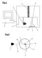
- FIG. 1 shows a side schematic view of an embodiment of the device according to the invention.
- FIG. 2 shows a schematic sectional view of the device FIG. 1 in a plane perpendicular to the in FIG. 1 shown view.
- FIG. 1 an embodiment of the device according to the invention is shown schematically.
- Basic elements of the device are a line camera 1 and a line-shaped illumination source 2. While the line scan camera 1 is arranged outside a substrate to be tested, here a drinking glass 3, the line-shaped illumination source 2 is arranged such that the line-shaped source is concentric with a drinking glass 3 to be detected is surrounded. In this case, the line extends substantially parallel to the axis of symmetry of the glass 3.
- the arrangement of the illumination source 2 and the line camera 1 by means of a linear adjuster 5 can be adjusted in height, so that after placing a drinking glass 3 on the substrate holder 4, the line-shaped illumination 2 automatically in the Drinking glass 3 can be lowered and after completion of the measurement can be pulled out of this again.
- an optical measuring sensor is provided at the lower end 7 of the illumination 2, which prevents in cooperation with the control of the device that the illumination 2 abuts against the bottom of the drinking glass 3.
- the measuring arrangement of line scan camera 1 and illumination 2 is surrounded by a height-adjustable flare cabin 11 which can be moved with the arrangement in height, which in operation, i. during a measurement, which prevents outside light from falling in and also absorbs scattered light from the source 2.
- the illustrated substrate holder 4 consists of a to the line-shaped lighting 2 concentrically mounted and driven about this axis by a motor, rotatable disc on which a drinking glass 3 can be accommodated.
- the substrate holder In order to enable a centered recording of drinking glasses 3 with different diameters on the foot, the substrate holder has concentric conical depressions about the axis of rotation, the depth of which increases from the edge of the substrate holder 4 towards the axis of rotation. As a result, glasses arranged on the substrate holder 4 are themselves centered. In the illustrated embodiment, this conical recess is stepped, so that the conical shape is realized only approximated. This step-shaped design allows a good fixation of glasses with different diameters.
- FIG. 2 is a schematic plan view of the in FIG. 1 shown arrangement to describe the alignment of the camera line and the illumination source and the structure of the illumination source in more detail.
- the line-shaped illumination source 2 within the drinking glass 3 to be measured, wherein the illumination source 2 coincides approximately with the axis of symmetry of the hollow cylindrical drinking glass 3 and the axis of rotation of the substrate holder 4.
- the light-emitting diodes 8 used have a spatial emission characteristic for the generated electromagnetic radiation with a maximum forward.
- the direction of the spatial intensity maximum is in FIG. 2 represented by the line marked I.
- the direct line connecting line-shaped illumination source 2 and line-shaped detector arrangement or camera 1 in FIG FIG. 2 denoted by V.
- the radiated spatial intensity maximum with respect to the connecting line V is rotated by 35 °. In this way it will be in the Image of the detector array 1 located glass cutout 10 of the lighting device 2 is illuminated substantially substantially indirectly.
- the maximum intensity emitted in the direction I is reflected and scattered on the inner surface of the drinking glass 3 and indirectly, but homogeneously, illuminates the glass cut-out 10 which is detected by the camera 1.
- Detergent residues on the drinking glass 3 is first a calibration measurement with an identical drinking glass, but which has no residues carried out. During each measurement, the drinking glass 3 to be measured is rotated about its axis, during which rotation the camera line 1 respectively captures the image section of the drinking glass lying on the connecting line V and thus measures cut-out by section of the glass. The control of the device and the quantitative evaluation of the detected processing of the contaminated drinking glass 3 is carried out by means of a personal computer. 6
Landscapes
- Physics & Mathematics (AREA)
- Health & Medical Sciences (AREA)
- Life Sciences & Earth Sciences (AREA)
- Chemical & Material Sciences (AREA)
- Analytical Chemistry (AREA)
- Biochemistry (AREA)
- General Health & Medical Sciences (AREA)
- General Physics & Mathematics (AREA)
- Immunology (AREA)
- Pathology (AREA)
- Investigating Or Analysing Materials By Optical Means (AREA)
- Investigating Materials By The Use Of Optical Means Adapted For Particular Applications (AREA)
Abstract
Description
- Die vorliegende Erfindung betrifft eine Vorrichtung zur Erfassung von Verunreinigungen auf einem zumindest teilweise transparenten Substrat sowie ein entsprechendes Verfahren.
- Moderne Geschirreinigungsmittel sind multifunktionale Produkte, die neben der Reinigung verschmutzten Geschirrs in einer Spülmaschine gleichzeitig auch das Klarspülen und die Wasserenthärtung durch den Zusatz spezieller dafür geeigneter Tenside und Polymere leisten.
- Für die Beurteilung der Leistungsfähigkeit eines solchen multifunktionalen Geschirrspülmittels für die maschinelle Geschirreinigung ist unter anderem die Klarspülleistung, insbesondere für Gläser, ausschlaggebend. Für diese Klarspülleistung sind in erster Linie die in den Geschirrspülmitteln vorhandenen Tenside verantwortlich. Diese sollen trotz der Zudosierung zu dem Geschirrspülmittel bereits im Hauptreinigungsgang ihre volle Wirkung erst im Klarspülgang entfalten. Kommt es im Ablauf der maschinellen Geschirreinigung zu Störungen oder entspricht das verwendete Geschirreinigungsmittel nicht den gestellten Anforderungen, so sind auf dem Geschirr nach dem Abschluß des Spülvorgangs kleine Flecken, als Spotting bezeichnet, sowie filmartige Beläge, als Filming bezeichnet, visuell wahrnehmbar.
- Zur Bewertung der Spülleistung der entsprechenden Geschirrspülmittel werden im Stand der Technik primär visuelle Verfahren verwendet. Dafür wird je nach Anforderung unter ausgewählten Bedingungen (z. B. Wasserhärte, Ballastschmutz, Dosierung etc.) eine verbraucherrelevante Geschirrbeladung in einer Haushaltsspülmaschine mit dem zu testenden Produkt gespült, und anschließend wird das derart gespülte Geschirr durch Personen visuell beurteilt. Trotz standardisierter Auswerteverfahren, die insbesondere auf schematischen Auswertebögen basieren, kann es in Abhängigkeit von der Routine und Erfahrung der jeweiligen Testperson zu deutlichen Schwankungen bei der Beurteilung der Leistungsfähigkeit der Geschirrspülmittel kommen.
- Aus der
EP 1 635 167 A1 ist ein Verfahren zur quantitativen Messung von Ablagerungen auf festen Oberflächen bekannt, wobei die zu messende Oberfläche als planer Prüfling ausgebildet ist, beispielsweise in Form einer rechteckigen oder runden Platte, und mit sichtbarem Licht aus einer Lichtquelle bestrahlt wird, wobei das von dem Prüfling reflektierte und/oder gestreute Licht von einer Kamera aufgenommen wird und das so gewonnene Bild computergestützt quantitativ ausgewertet wird. Dabei offenbart dieses Dokument aus dem Stand der Technik sowohl Messungen in Reflexion als auch in Transmission. Dabei werden sowohl zur Beleuchtung des Substrates als auch zur Erfassung der vom Substrat reflektierten oder gestreuten Strahlung flächige Elemente eingesetzt. - Die aus dem Stand der Technik bekannten automatisierten Bewertungsverfahren beruhen auf der optischen Erfassung der Reflexions- und Streuprozesse an Spotting und Filming auf Testsubstraten nach dem maschinellen Geschirrspülvorgang. Dabei werden ausschließlich plane Substrate als Modelle für Geschirr aus Metall, Porzellan und Glas verwendet. Diese planen Modelle vermögen jedoch die tatsächliche Spülleistung der Geschirrspülmittel insbesondere für Gläser nur ungenügend wiederzugeben. Gerade das Klarspülen von Trinkgläsern stellt aber bei der maschinellen Geschirreinigung ein ernsthaftes Problem dar, welches unter anderem durch die aufgrund der hohlzylindrischen Grundform von Trinkgläsern bedingte Krümmung der zu reinigenden Oberflächen hervorgerufen wird. Die im Stand der Technik verwendeten planen Substrate sind zwar vergleichsweise einfach zu messen, stellen jedoch in Bezug auf Trinkgläser ein zu stark vereinfachendes Modell dar.
- Daher ist es Aufgabe der vorliegenden Erfindung gegenüber dem Stand der Technik, eine Vorrichtung und ein Verfahren zur Verfügung zu stellen, welches es ermöglicht, Verunreinigungen auf gekrümmten transparenten Oberflächen, insbesondere auf Trinkgläsern quantitativ zu erfassen.
- Diese Aufgabe wird erfindungsgemäß dadurch gelöst, daß eine Vorrichtung zur Erfassung von Verunreinigungen auf einem zumindest teilweise transparenten Substrat, mit einer Quelle und einer zeilenförmigen Detektoranordnung für elektromagnetische Strahlung und mit einem Substrathalter für ein gekrümmtes Substrat, der so angeordnet ist, daß sich ein darin aufgenommenes gekrümmtes Substrat zumindest abschnittsweise zwischen der Quelle und der Detektoranordnung erstreckt, bereitgestellt wird.
- In einer Ausführungsform der Erfindung ist die Quelle für elektromagnetische Strahlung eine zeilenförmige Quelle.
- Dabei wird im Sinne der vorliegenden Erfindung unter "zeilenförmig" eine flächige Ausdehnung der Quelle und der Detektoranordnung verstanden, die in einer ersten Richtung deutlich größer ist als in einer zweiten zu der ersten Richtung senkrechten Richtung.
- Ein Beispiel für eine erfindungsgemäße zeilenförmige Quelle ist eine Anordnung einer Mehrzahl von nebeneinander, vorzugsweise in einer Reihe angeordneten Strahlungsquellen, vorzugsweise Leuchtdioden.
- Ein Beispiel für eine zeilenförmige Detektoranordnung gemäß der vorliegenden Erfindung ist eine CCD- oder CMOS-Zeilenkamera.
- Die zeilenförmige Ausgestaltung von Quelle und Detektoranordnung ermöglicht es, Verunreinigungen auf einem gekrümmten Substrat zu erfassen, ohne Artefakte aufgrund der Krümmung des Substrates gesondert numerisch berücksichtigen zu müssen.
- Erstreckt sich die zeilenförmige Detektoranordnung im Wesentlichen parallel zu der Achse eines im Wesentlichen hohlzylinderförmigen Substrates, so wird immer nur ein, idealerweise sehr kleiner, Winkelausschnitt der Oberfläche des gekrümmten Substrates erfaßt, dessen Krümmung dann für den betrachteten Bereich vernachlässigbar klein ist, so daß in diesem Bereich von der Erfassung eines nahezu planen Substrates ausgegangen werden kann.
- Dabei ist ein hohlzylinderförmiges Substrat im Sinne dieser Anmeldung ein Substrat mit einer Symmetrieachse, das eine zumindest um die Symmetrieachse herum gekrümmte Oberfläche aufweist, wie z.B. ein Trinkglases. Ein solches hohlzylindrisches Substrat kann darüber hinaus eine Krümmung in einer zweiten Richtung, wie z.B. bei einer Biertulpe, aufweisen.
- In einer Ausführungsform der Erfindung weist die Vorrichtung einen Substrathalter auf, der so angeordnet ist, daß sich ein darin aufgenommenes Substrat zwischen der Lichtquelle und der Detektoranordnung erstreckt, d.h. eine Messung in Transmission durch das Substrat erfolgt.
- Eine Ausführungsform der erfindungsgemäßen Vorrichtung ist insbesondere für die Erfassung von Verunreinigungen auf Trinkgläsern geeignet, wobei der Substrathalter so ausgestaltet ist, daß er die Aufnahme eines im Wesentlichen hohlzylindrischen Substrates ermöglicht, wobei sich die Quelle oder die zeilenförmige Detektoranordnung im Betrieb der Vorrichtung in dem hohlzylindrischen Substrat befindet. Auf diese Weise wird in Transmission nur ein sehr kleiner Ausschnitt des Hohlzylinders mit Hilfe der zeilenförmigen Detektoranordnung erfaßt.
- Um dennoch die gesamte Substratoberfläche eines in dem Substrathalter aufgenommenen Substrates erfassen zu können, ist eine Ausführungsform der Erfindung zweckmäßig, bei welcher der Substrathalter eine Drehachse aufweist und so drehbar ist, daß ein in dem Substrathalter aufgenommenes im Wesentlichen hohlzylindrisches Substrat im Wesentlichen konzentrisch um die zeilenförmige Quelle oder die zeilenförmige Detektoranordnung herum drehbar ist.
- Insbesondere ist eine Ausführungsform der Erfindung zweckmäßig, bei der sich die Zeile der Quelle und/oder der Detektoranordnung im Wesentlichen parallel zur Drehachse des Substrathalters erstreckt.
- In einer Ausführungsform der Erfindung wird der von der zeilenförmigen Detektoranordnung erfaßte Ausschnitt des Substrates nur indirekt beleuchtet.
- In einer Ausführungsform der Erfindung weist die Quelle daher eine räumliche Abstrahlung mit einem räumlichen Intensitätsmaximum auf, wobei das räumliche Intensitätsmaximum der Quelle gegenüber einer Verbindungslinie zwischen der Quelle und der Detektoranordnung, d.h. der direkten Sichtverbindung, verkippt ist. Vorteilhafterweise liegt diese Verkippung in einem Bereich von 1° bis 90°, bevorzugt in einem Bereich von 30° bis 40° und besonders bevorzugt bei etwa 35°. Dies ist insbesondere vorteilhaft für Ausführungsformen der Erfindung, bei welchen die Quelle im Inneren eines hohlzylindrischen Substrates angeordnet ist, das in dem Substrathalter aufgenommen ist.
- Die Verkippung des Abstrahlungsmaximums aus der direkten Sichtverbindung zwischen Quelle und Detektoranordnung verhindert ein Überstrahlen, d.h. eine Sättigung der Detektoranordnung.
- Darüber hinaus unterscheidet sich der bilderzeugende Mechanismus bei einer Messung mit indirekter Beleuchtung deutlich von einer reinen Transmissionsmessung. Bei einer reinen Transmissionsmessung wird das Substrat zumindest ausschnittsweise direkt beleuchtet, so daß das räumliche Intensitätsmaximum der Quelle im Wesentlichen in Richtung der Verbindungslinie (Sichtlinie) zwischen Quelle und Detektorzeile abgestrahlt wird. Daher führen Verunreinigungen auf einem transparenten Substrat, insbesondere Spotting und Filming auf einem Glas, die in einem Abschnitt des Substrats liegen, der von der Verbindungslinie zwischen Quelle und Detektor geschnitten wird, zu einer Verringerung der Transmission durch das transparente Substrat aufgrund von Absorption, Streuung und Reflexion an den Verunreinigungen. Diese Verringerung der Transmission wird von der Detektoranordnung als Verdunklung bestimmter Bereiche erfaßt. Diese Änderungen der Transmission sind verglichen mit der durch das Substrat transmittierten Leistung gering.
- Demgegenüber führt eine indirekte Beleuchtung in einer Ausführungsform der Erfindung, beispielsweise durch Verkippen des räumlichen Intensitätsmaximums der Quelle gegenüber der Verbindungslinie zwischen Quelle und Detektor, dazu, daß bei einem sauberen Substrat im Wesentlichen keine Strahlung direkt, d.h entlang der Verbindungslinie zwischen der Quelle und dem Detektor, durch das Substrat transmittiert wird. Erst Verunreinigungen auf dem Substrat, die im Bereich des Bildfeldes der Detektoranordnung liegen, führen zu einer Streuung von Strahlung, die von der Quelle abgestrahlt und an einem außerhalb des Sichtfeldes des Detektors liegenden Abschnitt des Substrates reflektiert oder gestreut wird, in das Bildfeld der zeilenförmigen Detektoranordnung. Daher erscheinen Verunreinigungen auf dem Substrat bei einer solchen Anordnung mit indirekter Beleuchtung in dem von der Detektoranordnung aufgenommenen Bild als helle Bereiche. Da bei einem sauberen Substrat keine Strahlung auf die Detektoranordnung fällt, führen bereits geringe Verunreinigungen zu einem deutlichen Kontrast der Verunreinigungen gegenüber den sauberen Bereichen des Substrats.
- Darüber hinaus wird ein gegenüber der Verbindungslinie zwischen Quelle und Detektoranordnung verkipptes räumliches Intensitätsmaximum an der Substratoberfläche eines in dem Substrathalter aufgenommenen, im Wesentlichen hohlzylindrischen Substrats diffus gestreut bzw. reflektiert, so daß die außerhalb des Substrates angeordnete Detektoranordnung die zeilenförmige Quelle als diffuse und homogene Beleuchtung des Substrates wahrnimmt.
- In einer Ausführungsform ist die Quelle aus einer Mehrzahl von nebeneinander, vorzugsweise in einer Reihe, angeordneten Quellen, beispielsweise Leuchtdioden, aufgebaut.
- Gemäß einer weiteren Ausführungsform der Erfindung ist die Quelle eine Quelle für elektromagnetische Strahlung in einem Wellenlängenbereich von 350 nm bis 500 nm, vorzugsweise bei 435 nm. Dieser Wellenlängenbereich ermöglicht eine möglichst homogene Ausleuchtung des von der zeilenförmigen Detektoranordnung erfaßten Substratausschnittes, d.h. eine gleichmäßige räumliche Intensitätsverteilung des erfaßten Bereichs. Er liefert darüber hinaus die besten Kontraste für Verunreinigung auf Glasoberflächen, da in dem genannten Wellenlängenbereich die Verunreinigungen auf dem Substrat, insbesondere Rückstände eines Geschirrspülmittels die stärkste Streuung zeigen.
- Die vorliegende Aufgabe wird darüber hinaus durch ein Verfahren zur Erfassung von Verunreinigungen auf einem zumindest teilweise transparenten Substrat gelöst, wobei Verunreinigungen auf einer gekrümmten Substratoberfläche, vorzugsweise der Oberfläche eines Trinkglases mit Hilfe einer Quelle für elektromagnetische Strahlung und einer zeilenförmige Detektoranordnung erfaßt werden.
- Dabei ist eine Ausführungsform des Verfahrens zweckmäßig, bei welchem das im Wesentlichen hohlzylinderförmige Substrat während der Erfassung um seine Zylinderachse gedreht wird, um die gesamte Oberfläche eines Substrates, beispielsweise eines Trinkglases, als Abwicklung zu erfassen.
- Weitere Vorteile, Merkmale und Anwendungsmöglichkeiten der vorliegenden Erfindung werden anhand der folgenden Beschreibung einer bevorzugten Ausführungsform und der dazugehörigen Figuren deutlich.
-
Figur 1 zeigt eine seitliche schematische Ansicht einer Ausführungsform der erfindungsgemäßen Vorrichtung. -
Figur 2 zeigt eine schematische Schnittansicht der Vorrichtung ausFigur 1 in einer Ebene senkrecht zu der inFigur 1 gezeigten Ansicht. - In
Figur 1 ist eine Ausführungsform der erfindungsgemäßen Vorrichtung schematisch dargestellt. Grundelemente der Vorrichtung sind eine Zeilenkamera 1 sowie eine zeilenförmige Beleuchtungsquelle 2. Während die Zeilenkamera 1 außerhalb eines zu testenden Substrats, hier eines Trinkglases 3, angeordnet ist, ist die zeilenförmige Beleuchtungsquelle 2 so angeordnet, daß die zeilenförmige Quelle konzentrisch von einem zu erfassenden Trinkglas 3 umgeben ist. Dabei erstreckt sich die Zeile im Wesentlichen parallel zur Symmetrieachse des Glases 3. - Um einen automatisierten Betrieb der Vorrichtung zu ermöglichen, kann die Anordnung aus der Beleuchtungsquelle 2 und der Zeilenkamera 1 mit Hilfe eines Linearverstellers 5 in der Höhe eingestellt werden, so daß nach dem Aufstellen eines Trinkglases 3 auf den Substrathalter 4 die zeilenförmige Beleuchtung 2 automatisch in das Trinkglas 3 abgesenkt werden kann und nach Abschluß der Messung wieder aus diesem herausgezogen werden kann. Dabei ist am unteren Ende 7 der Beleuchtung 2 ein optischer Meßsensor vorgesehen, der im Zusammenwirken mit der Steuerung der Vorrichtung verhindert, daß die Beleuchtung 2 gegen den Boden des Trinkglases 3 stößt.
- Die Meßanordnung aus Zeilenkamera 1 und Beleuchtung 2 ist von einer mit der Anordnung in der Höhe bewegbaren Streulichtkabine 11 umgeben, welche im Betrieb, d.h. während einer Messung, das Einfallen von Streulicht von außen verhindert und darüber hinaus Streulicht der Quelle 2 absorbiert.
- Der dargestellte Substrathalter 4 besteht aus einer zu der zeilenförmigen Beleuchtung 2 konzentrisch montierten und um diese Achse durch einen Motor angetriebenen, drehbaren Scheibe, auf der ein Trinkglas 3 aufgenommen werden kann.
- Um eine zentrierte Aufnahme von Trinkgläsern 3 mit unterschiedlichen Durchmessern am Fuß zu ermöglichen, weist die Substrataufnahme um die Drehachse konzentrische konische Vertiefungen auf, deren Tiefe vom Rand des Substrathalters 4 hin zur Drehachse zunimmt. Dadurch werden auf dem Substrathalter 4 angeordnete Gläser selbst zentriert. In der dargestellten Ausführungsform ist diese konische Ausnehmung stufenförmig ausgeführt, so daß die konische Form nur genähert realisiert ist. Diese stufenförmige Ausgestaltung ermöglicht eine gute Fixierung von Gläsern mit unterschiedlichem Durchmesser.
- In
Figur 2 ist schematisch eine Draufsicht auf die inFigur 1 dargestellte Anordnung gezeigt, um die Ausrichtung der Kamerazeile und der Beleuchtungsquelle sowie den Aufbau der Beleuchtungsquelle detaillierter zu beschreiben. - Deutlich zu erkennen ist die Anordnung der zeilenförmigen Beleuchtungsquelle 2 innerhalb des zu messenden Trinkglases 3, wobei die Beleuchtungsquelle 2 in etwa mit der Symmetrieachse des hohlzylinderförmigen Trinkglases 3 und der Drehachse des Substrathalters 4 zusammenfällt.
- In der dargestellten Ausführungsform ist die zeilenförmige Beleuchtung aus einer Reihe von nebeneinander angeordneten Leuchtdioden 8, die an einem Träger 9 befestigt sind, aufgebaut. Die verwendeten Leuchtdioden 8 weisen eine räumliche Abstrahlcharakteristik für die erzeugte elektromagnetische Strahlung mit einem Maximum nach vorne auf. Dabei ist die Richtung des räumlichen Intensitätsmaximums in
Figur 2 durch die mit I gekennzeichnete Linie dargestellt. Demgegenüber ist die direkte Verbindungslinie zwischen zeilenförmiger Beleuchtungsquelle 2 und zeilenförmiger Detektoranordnung bzw. Kamera 1 inFigur 2 mit V bezeichnet. Deutlich ist erkennbar, daß in der dargestellten Ausführungsform das abgestrahlte räumliche Intensitätsmaximum gegenüber der Verbindungslinie V um 35° verdreht ist. Auf diese Weise wird der sich im Bildfeld der Detektoranordnung 1 befindliche Glasausschnitt 10 von der Beleuchtungsanordnung 2 im Wesentlichen indirekt beleuchtet. Die in Richtung I abgestrahlte maximale Intensität wird an der Innenfläche des Trinkglases 3 reflektiert und gestreut und beleuchtet indirekt, aber homogen, den Glasausschnitt 10, der von der Kamera 1 erfaßt wird. - Für eine quantitative Erfassung von Flecken und Filmen, d.h. Spülmittelrückständen, auf dem Trinkglas 3 wird zunächst eine Kalibrierungsmessung mit einem identischen Trinkglas, das jedoch keine Rückstände aufweist, durchgeführt. Bei jeder Messung wird das zu messende Trinkglas 3 um seine Achse gedreht, wobei während der Drehung die Kamerazeile 1 jeweils den auf der Verbindungslinie V liegenden Bildausschnitt des Trinkglases erfaßt und so Ausschnitt für Ausschnitt eine Abwicklung des Glases mißt. Die Steuerung der Vorrichtung sowie die quantitative Auswertung der erfaßten Abwicklung des verunreinigten Trinkglases 3 erfolgt mit Hilfe eines Personalcomputers 6.
- Für Zwecke der ursprünglichen Offenbarung wird darauf hingewiesen, daß sämtliche Merkmale, wie sie sich aus der vorliegenden Beschreibung, den Zeichnungen und den Ansprüchen für einen Fachmann erschließen, auch wenn sie konkret nur im Zusammenhang mit bestimmten weiteren Merkmalen beschrieben wurden, sowohl einzeln als auch in beliebigen Zusammenstellungen mit anderen der hier offenbarten Merkmale oder Merkmalsgruppen kombinierbar sind, soweit dies nicht ausdrücklich ausgeschlossen wurde oder technische Gegebenheiten derartige Kombinationen unmöglich oder sinnlos machen. Auf die umfassende, explizite Darstellung sämtlicher denkbarer Merkmalskombinationen wird hier nur der Kürze und der Lesbarkeit der Beschreibung wegen verzichtet.
- Während die vorangegangene Beschreibung viele Einzelheiten enthält, sollen diese nicht als Beschränkungen des Schutzbereiches der Erfindung verstanden werden, sondern vielmehr als eine beispielhafte Beschreibung einer bevorzugten Ausführungsform der Erfindung. Viele andere Varianten sind möglich. Entsprechend sollte der Schutzbereich der Erfindung nicht durch die dargestellte Ausführungsform sondern durch die beigefügten Ansprüche und ihre rechtlichen Äquivalente definiert werden.
-
- 1
- Zeilenkamera
- 2
- zeilenförmige Beleuchtungsquelle
- 3
- Trinkglas
- 4
- Substrathalter
- 5
- Linearversteller
- 6
- Personalcomputer
- 7
- unteres Ende der Beleuchtung
- 8
- Leuchtdiode
- 9
- Träger
- 10
- Glasausschnitt im Gesichtsfeld der Zeilenkamera
- 11
- Streulichtkabine
Claims (13)
- Vorrichtung zur Erfassung von Verunreinigungen auf einem zumindest teilweise transparenten Substrat, mit einer Quelle (2) und einer zeilenförmigen Detektoranordnung (1) für elektromagnetische Strahlung und mit einem Substrathalter (4) für ein gekrümmtes Substrat, der so angeordnet ist, daß sich ein darin aufgenommenes gekrümmtes Substrat zumindest abschnittsweise zwischen der Quelle (2) und der Detektoranordnung (1) erstreckt.
- Vorrichtung nach Anspruch 1, dadurch gekennzeichnet, daß die Quelle für elektromagnetische Strahlung eine zeilenförmige Quelle (2) ist.
- Vorrichtung nach Anspruch 1 oder 2, dadurch gekennzeichnet, daß der Substrathalter (4) so ausgestaltet ist, daß er die Aufnahme eines im Wesentlichen hohlzylindrischen Substrates ermöglicht, und daß der Substrathalter (4) so angeordnet ist, daß sich die Quelle oder die zeilenförmige Detektoranordnung (1) im Betrieb der Vorrichtung in dem hohlzylindrischen Substrat befindet.
- Vorrichtung nach einem der Ansprüche 1 bis 3, dadurch gekennzeichnet, daß der Substrathalter (4) um eine Drehachse drehbar ist, wobei ein im Wesentlichen hohlzylindrisches, in dem Substrathalter aufgenommenes Substrat im Wesentlichen konzentrisch um die Quelle oder die zeilenförmige Detektoranordnung (1) herum drehbar ist.
- Vorrichtung nach Anspruch 4, dadurch gekennzeichnet, daß sich die Zeile der Quelle (2) und/oder der Detektoranordnung (1) im Wesentlichen parallel zur Drehachse des Substrathalters erstreckt.
- Vorrichtung nach einem der Ansprüche 1 bis 5, dadurch gekennzeichnet, daß die Quelle (2) für elektromagnetische Strahlung eine Mehrzahl von nebeneinander, vorzugsweise in einer Reihe angeordneten Strahlungsquellen (8), vorzugsweise Leuchtdioden, aufweist.
- Vorrichtung nach einem der Ansprüche 1 bis 6, dadurch gekennzeichnet, daß die Quelle (2) eine räumliche Abstrahlung mit einem räumlichen Intensitätsmaximum aufweist, wobei das räumliche Intensitätsmaximum der Quelle (2) gegenüber einer Verbindungslinie (V) zwischen der Quelle (2) und der Detektoranordnung (1) verkippt ist und zwar vorzugsweise um 30° bis 40° und besonders bevorzugt um etwa 35°.
- Vorrichtung nach einem der Ansprüche 1 bis 7, dadurch gekennzeichnet, daß die Quelle (1) eine Quelle für elektromagnetische Strahlung in einem Wellenlängenbereich von 350 nm bis 500 nm, vorzugsweise bei etwa 435 nm ist.
- Verfahren zur Erfassung von Verunreinigungen auf einem zumindest teilweise transparenten Substrat, dadurch gekennzeichnet, daß Verunreinigungen auf einem zumindest teilweise gekrümmten Substrat mit Hilfe einer Quelle (2) für elektromagnetische Strahlung und einer zeilenförmigen Detektoranordnung (1) erfaßt werden.
- Verfahren nach Anspruch 9, dadurch gekennzeichnet, daß Verunreinigungen auf einem hohlzylinderförmigen Substrat erfaßt werden.
- Verfahren nach Anspruch 9 oder 10, dadurch gekennzeichnet, daß Verunreinigungen auf einem im Wesentlichen hohlzylinderförmigen Substrat erfaßt werden, wobei das hohlzylinderförmige Substrat im Wesentlichen konzentrisch um die Quelle (2) oder um die zeilenförmige Detektoranordnung (1) herum angeordnet ist.
- Verfahren nach einem der Ansprüche 9 bis 11, dadurch gekennzeichnet, daß das im Wesentlichen hohlzylinderförmige Substrat (3) während der Erfassung um seine Zylinderachse gedreht wird.
- Verwendung einer Vorrichtung nach einem der Ansprüche 1 bis 8, dadurch gekennzeichnet, daß sie zur Erfassung von Verunreinigungen auf einem Trinkglas verwendet wird.
Applications Claiming Priority (1)
| Application Number | Priority Date | Filing Date | Title |
|---|---|---|---|
| DE102007013086A DE102007013086A1 (de) | 2007-03-14 | 2007-03-14 | Vorrichtung und Verfahren zur Erfassung von Verunreinigungen auf einem transparenten Substrat |
Publications (3)
| Publication Number | Publication Date |
|---|---|
| EP1970699A2 true EP1970699A2 (de) | 2008-09-17 |
| EP1970699A3 EP1970699A3 (de) | 2008-12-10 |
| EP1970699B1 EP1970699B1 (de) | 2010-02-17 |
Family
ID=39473197
Family Applications (1)
| Application Number | Title | Priority Date | Filing Date |
|---|---|---|---|
| EP08102500A Not-in-force EP1970699B1 (de) | 2007-03-14 | 2008-03-11 | Vorrichtung und Verfahren zur Erfassung von Verunreinigungen auf einem transparenten Substrat |
Country Status (4)
| Country | Link |
|---|---|
| EP (1) | EP1970699B1 (de) |
| AT (1) | ATE458193T1 (de) |
| DE (2) | DE102007013086A1 (de) |
| RU (1) | RU2461816C2 (de) |
Citations (1)
| Publication number | Priority date | Publication date | Assignee | Title |
|---|---|---|---|---|
| GB1041798A (en) | 1962-09-06 | 1966-09-07 | Fords Ltd | Apparatus for detecting dirt in transparent bottles |
Family Cites Families (10)
| Publication number | Priority date | Publication date | Assignee | Title |
|---|---|---|---|---|
| GB758850A (en) * | 1954-02-16 | 1956-10-10 | Gen Electric Co Ltd | Improvements in or relating to methods of detecting dirty transparent containers |
| DE3108234A1 (de) * | 1981-03-05 | 1982-09-30 | Fraunhofer-Gesellschaft zur Förderung der angewandten Forschung e.V., 8000 München | "verfahren zur beurteilung der qualitaet von kfz-scheiben" |
| DE4022733C1 (en) * | 1989-12-19 | 1991-05-08 | Elpatronic Ag, Zug, Ch | Three=dimensional cavity inspection appts. - uses matrix or line camera to receive reflected light via gp. of four mirrors and deflecting mirror |
| DK17791D0 (da) * | 1991-02-01 | 1991-02-01 | Novo Nordisk As | Beholderinspektion |
| DE19806559B4 (de) * | 1998-02-17 | 2015-10-29 | BSH Hausgeräte GmbH | Verfahren und Vorrichtung zur Behandlung von Geschirr in Spülmaschinen |
| DE19904280B4 (de) * | 1999-02-03 | 2005-08-18 | BSH Bosch und Siemens Hausgeräte GmbH | Vorrichtung und Verfahren zur Ermittlung von Ablagerungen an Glasoberflächen in Spülmaschinen |
| FR2798995B1 (fr) * | 1999-09-27 | 2002-04-12 | Bsn | Installation pour determiner les caracteristiques de transmission lumineuse du materiau constitutif d'un recipient |
| DE10208214B4 (de) * | 2002-02-26 | 2004-09-30 | BSH Bosch und Siemens Hausgeräte GmbH | Vorrichtung zur Überprüfung der Belagbildung und wasserführendes Gerät |
| US7342654B2 (en) * | 2003-12-19 | 2008-03-11 | International Business Machines Corporation | Detection of impurities in cylindrically shaped transparent media |
| ES2295749T3 (es) * | 2004-09-10 | 2008-04-16 | Cognis Ip Management Gmbh | Procedimiento para la medida cuantitativa de los depositos sobre superficies solidas. |
-
2007
- 2007-03-14 DE DE102007013086A patent/DE102007013086A1/de not_active Withdrawn
-
2008
- 2008-03-11 DE DE502008000365T patent/DE502008000365D1/de active Active
- 2008-03-11 AT AT08102500T patent/ATE458193T1/de active
- 2008-03-11 EP EP08102500A patent/EP1970699B1/de not_active Not-in-force
- 2008-03-13 RU RU2008109311/28A patent/RU2461816C2/ru not_active IP Right Cessation
Patent Citations (1)
| Publication number | Priority date | Publication date | Assignee | Title |
|---|---|---|---|---|
| GB1041798A (en) | 1962-09-06 | 1966-09-07 | Fords Ltd | Apparatus for detecting dirt in transparent bottles |
Also Published As
| Publication number | Publication date |
|---|---|
| EP1970699B1 (de) | 2010-02-17 |
| DE102007013086A1 (de) | 2008-09-18 |
| ATE458193T1 (de) | 2010-03-15 |
| RU2008109311A (ru) | 2009-09-20 |
| EP1970699A3 (de) | 2008-12-10 |
| DE502008000365D1 (de) | 2010-04-01 |
| RU2461816C2 (ru) | 2012-09-20 |
Similar Documents
| Publication | Publication Date | Title |
|---|---|---|
| EP1982159B1 (de) | Messvorrichtung zur bestimmung der grösse, grössenverteilung und menge von partikeln im nanoskopischen bereich | |
| DE102007006525B4 (de) | Verfahren und Vorrichtung zur Detektierung von Defekten | |
| EP2551663B1 (de) | Vorrichtung und Verfahren zur Untersuchung von Beschichtungen mit Effektpigmenten | |
| DE102012101377B4 (de) | Verfahren bei der Vorbereitung von Proben zum Mikroskopieren und Vorrichtung zum Überprüfen der Eindeckqualität von Proben | |
| DE102008047085B4 (de) | Beleuchtungsvorrichtung | |
| DE202010018630U1 (de) | Vorrichtung zur Detektion von Rissen in Halbleitersubstraten | |
| DE3516752A1 (de) | System zur erfassung von selektiven lichtbrechenden defekten in transparenten gegenstaenden | |
| EP2390656A2 (de) | Einrichtung und Verfahren zur optischen Überprüfung | |
| WO2005116616A1 (de) | Vorrichtung und verfahren zur detektion von kratzern | |
| DE102005014415B3 (de) | Vorrichtung und Verfahren zur Untersuchung einer gewölbten Oberfläche | |
| DE202009011911U1 (de) | Vorrichtung zur Prüfung des Innenschraubgewindes einer Schraubenmutter | |
| DE102006008840B4 (de) | Beleuchtungsvorrichtung für zylindrische Objekte, damit durchgeführtes Oberflächenuntersuchungsverfahren und Computerprogrammprodukt | |
| EP1970699B1 (de) | Vorrichtung und Verfahren zur Erfassung von Verunreinigungen auf einem transparenten Substrat | |
| DE10208214B4 (de) | Vorrichtung zur Überprüfung der Belagbildung und wasserführendes Gerät | |
| DE19713973C2 (de) | Verfahren und Vorrichtung zum optischen Prüfen der Mantelfläche zylindrischer Körper | |
| WO2010015696A1 (de) | Inspektionsvorrichtung- und verfahren für die optische untersuchung von objektoberflächen, insbesondere einer wafernotch | |
| DE102008018096A1 (de) | Vorrichtung zum Untersuchen von Oberflächeneigenschaften von Objekten | |
| DE10157244B4 (de) | Verfahren und Vorrichtung zur Defektanalyse von Wafern | |
| DE102015105128B4 (de) | Verfahren und Vorrichtung zur Messung des Glanzgrads und/oder der Mattheit von Gegenständen | |
| DE60115064T2 (de) | Analyseeinrichtung und -verfahren für flüssigkeitshaltige substanzen | |
| DE112009001936B4 (de) | Inspektionsvorrichtung- und Verfahren für die optische Untersuchung von Objektoberflächen, insbesondere von Waferkanten | |
| DE9421343U1 (de) | Vorrichtung zum Einkoppeln von Licht in einen Lichtleiter | |
| DE102019101734B4 (de) | Beleuchtungseinrichtung für ein abbildendes optisches Gerät sowie Verfahren zur optischen Analyse eines Objektes | |
| DE10356765A1 (de) | Optische Messvorrichtung und optisches Messverfahren | |
| EP3754324B1 (de) | Verfahren und vorrichtung zum klassifizieren einer partikelartigen verunreinigung auf einer oberfläche |
Legal Events
| Date | Code | Title | Description |
|---|---|---|---|
| PUAI | Public reference made under article 153(3) epc to a published international application that has entered the european phase |
Free format text: ORIGINAL CODE: 0009012 |
|
| AK | Designated contracting states |
Kind code of ref document: A2 Designated state(s): AT BE BG CH CY CZ DE DK EE ES FI FR GB GR HR HU IE IS IT LI LT LU LV MC MT NL NO PL PT RO SE SI SK TR |
|
| AX | Request for extension of the european patent |
Extension state: AL BA MK RS |
|
| PUAL | Search report despatched |
Free format text: ORIGINAL CODE: 0009013 |
|
| AK | Designated contracting states |
Kind code of ref document: A3 Designated state(s): AT BE BG CH CY CZ DE DK EE ES FI FR GB GR HR HU IE IS IT LI LT LU LV MC MT NL NO PL PT RO SE SI SK TR |
|
| AX | Request for extension of the european patent |
Extension state: AL BA MK RS |
|
| 17P | Request for examination filed |
Effective date: 20090326 |
|
| 17Q | First examination report despatched |
Effective date: 20090507 |
|
| AKX | Designation fees paid |
Designated state(s): AT BE BG CH CY CZ DE DK EE ES FI FR GB GR HR HU IE IS IT LI LT LU LV MC MT NL NO PL PT RO SE SI SK TR |
|
| GRAP | Despatch of communication of intention to grant a patent |
Free format text: ORIGINAL CODE: EPIDOSNIGR1 |
|
| GRAS | Grant fee paid |
Free format text: ORIGINAL CODE: EPIDOSNIGR3 |
|
| GRAA | (expected) grant |
Free format text: ORIGINAL CODE: 0009210 |
|
| AK | Designated contracting states |
Kind code of ref document: B1 Designated state(s): AT BE BG CH CY CZ DE DK EE ES FI FR GB GR HR HU IE IS IT LI LT LU LV MC MT NL NO PL PT RO SE SI SK TR |
|
| REG | Reference to a national code |
Ref country code: GB Ref legal event code: FG4D Free format text: NOT ENGLISH |
|
| REG | Reference to a national code |
Ref country code: CH Ref legal event code: EP |
|
| REG | Reference to a national code |
Ref country code: IE Ref legal event code: FG4D Free format text: LANGUAGE OF EP DOCUMENT: GERMAN |
|
| REF | Corresponds to: |
Ref document number: 502008000365 Country of ref document: DE Date of ref document: 20100401 Kind code of ref document: P |
|
| REG | Reference to a national code |
Ref country code: NL Ref legal event code: VDEP Effective date: 20100217 |
|
| LTIE | Lt: invalidation of european patent or patent extension |
Effective date: 20100217 |
|
| PG25 | Lapsed in a contracting state [announced via postgrant information from national office to epo] |
Ref country code: NO Free format text: LAPSE BECAUSE OF FAILURE TO SUBMIT A TRANSLATION OF THE DESCRIPTION OR TO PAY THE FEE WITHIN THE PRESCRIBED TIME-LIMIT Effective date: 20100517 Ref country code: LT Free format text: LAPSE BECAUSE OF FAILURE TO SUBMIT A TRANSLATION OF THE DESCRIPTION OR TO PAY THE FEE WITHIN THE PRESCRIBED TIME-LIMIT Effective date: 20100217 Ref country code: IS Free format text: LAPSE BECAUSE OF FAILURE TO SUBMIT A TRANSLATION OF THE DESCRIPTION OR TO PAY THE FEE WITHIN THE PRESCRIBED TIME-LIMIT Effective date: 20100617 Ref country code: HR Free format text: LAPSE BECAUSE OF FAILURE TO SUBMIT A TRANSLATION OF THE DESCRIPTION OR TO PAY THE FEE WITHIN THE PRESCRIBED TIME-LIMIT Effective date: 20100217 Ref country code: ES Free format text: LAPSE BECAUSE OF FAILURE TO SUBMIT A TRANSLATION OF THE DESCRIPTION OR TO PAY THE FEE WITHIN THE PRESCRIBED TIME-LIMIT Effective date: 20100528 |
|
| PG25 | Lapsed in a contracting state [announced via postgrant information from national office to epo] |
Ref country code: SI Free format text: LAPSE BECAUSE OF FAILURE TO SUBMIT A TRANSLATION OF THE DESCRIPTION OR TO PAY THE FEE WITHIN THE PRESCRIBED TIME-LIMIT Effective date: 20100217 Ref country code: PL Free format text: LAPSE BECAUSE OF FAILURE TO SUBMIT A TRANSLATION OF THE DESCRIPTION OR TO PAY THE FEE WITHIN THE PRESCRIBED TIME-LIMIT Effective date: 20100217 Ref country code: LV Free format text: LAPSE BECAUSE OF FAILURE TO SUBMIT A TRANSLATION OF THE DESCRIPTION OR TO PAY THE FEE WITHIN THE PRESCRIBED TIME-LIMIT Effective date: 20100217 Ref country code: FI Free format text: LAPSE BECAUSE OF FAILURE TO SUBMIT A TRANSLATION OF THE DESCRIPTION OR TO PAY THE FEE WITHIN THE PRESCRIBED TIME-LIMIT Effective date: 20100217 |
|
| REG | Reference to a national code |
Ref country code: IE Ref legal event code: FD4D |
|
| BERE | Be: lapsed |
Owner name: SGS INSTITUT FRESENIUS G.M.B.H. Effective date: 20100331 |
|
| PG25 | Lapsed in a contracting state [announced via postgrant information from national office to epo] |
Ref country code: SE Free format text: LAPSE BECAUSE OF FAILURE TO SUBMIT A TRANSLATION OF THE DESCRIPTION OR TO PAY THE FEE WITHIN THE PRESCRIBED TIME-LIMIT Effective date: 20100217 Ref country code: RO Free format text: LAPSE BECAUSE OF FAILURE TO SUBMIT A TRANSLATION OF THE DESCRIPTION OR TO PAY THE FEE WITHIN THE PRESCRIBED TIME-LIMIT Effective date: 20100217 Ref country code: MC Free format text: LAPSE BECAUSE OF NON-PAYMENT OF DUE FEES Effective date: 20100331 Ref country code: CY Free format text: LAPSE BECAUSE OF FAILURE TO SUBMIT A TRANSLATION OF THE DESCRIPTION OR TO PAY THE FEE WITHIN THE PRESCRIBED TIME-LIMIT Effective date: 20100217 Ref country code: EE Free format text: LAPSE BECAUSE OF FAILURE TO SUBMIT A TRANSLATION OF THE DESCRIPTION OR TO PAY THE FEE WITHIN THE PRESCRIBED TIME-LIMIT Effective date: 20100217 Ref country code: GR Free format text: LAPSE BECAUSE OF FAILURE TO SUBMIT A TRANSLATION OF THE DESCRIPTION OR TO PAY THE FEE WITHIN THE PRESCRIBED TIME-LIMIT Effective date: 20100518 Ref country code: IE Free format text: LAPSE BECAUSE OF FAILURE TO SUBMIT A TRANSLATION OF THE DESCRIPTION OR TO PAY THE FEE WITHIN THE PRESCRIBED TIME-LIMIT Effective date: 20100217 Ref country code: NL Free format text: LAPSE BECAUSE OF FAILURE TO SUBMIT A TRANSLATION OF THE DESCRIPTION OR TO PAY THE FEE WITHIN THE PRESCRIBED TIME-LIMIT Effective date: 20100217 |
|
| PG25 | Lapsed in a contracting state [announced via postgrant information from national office to epo] |
Ref country code: CZ Free format text: LAPSE BECAUSE OF FAILURE TO SUBMIT A TRANSLATION OF THE DESCRIPTION OR TO PAY THE FEE WITHIN THE PRESCRIBED TIME-LIMIT Effective date: 20100217 Ref country code: BG Free format text: LAPSE BECAUSE OF FAILURE TO SUBMIT A TRANSLATION OF THE DESCRIPTION OR TO PAY THE FEE WITHIN THE PRESCRIBED TIME-LIMIT Effective date: 20100517 Ref country code: SK Free format text: LAPSE BECAUSE OF FAILURE TO SUBMIT A TRANSLATION OF THE DESCRIPTION OR TO PAY THE FEE WITHIN THE PRESCRIBED TIME-LIMIT Effective date: 20100217 |
|
| PLBE | No opposition filed within time limit |
Free format text: ORIGINAL CODE: 0009261 |
|
| STAA | Information on the status of an ep patent application or granted ep patent |
Free format text: STATUS: NO OPPOSITION FILED WITHIN TIME LIMIT |
|
| 26N | No opposition filed |
Effective date: 20101118 |
|
| PG25 | Lapsed in a contracting state [announced via postgrant information from national office to epo] |
Ref country code: DK Free format text: LAPSE BECAUSE OF FAILURE TO SUBMIT A TRANSLATION OF THE DESCRIPTION OR TO PAY THE FEE WITHIN THE PRESCRIBED TIME-LIMIT Effective date: 20100217 |
|
| PG25 | Lapsed in a contracting state [announced via postgrant information from national office to epo] |
Ref country code: BE Free format text: LAPSE BECAUSE OF NON-PAYMENT OF DUE FEES Effective date: 20100331 |
|
| PG25 | Lapsed in a contracting state [announced via postgrant information from national office to epo] |
Ref country code: IT Free format text: LAPSE BECAUSE OF FAILURE TO SUBMIT A TRANSLATION OF THE DESCRIPTION OR TO PAY THE FEE WITHIN THE PRESCRIBED TIME-LIMIT Effective date: 20100217 |
|
| PG25 | Lapsed in a contracting state [announced via postgrant information from national office to epo] |
Ref country code: MT Free format text: LAPSE BECAUSE OF FAILURE TO SUBMIT A TRANSLATION OF THE DESCRIPTION OR TO PAY THE FEE WITHIN THE PRESCRIBED TIME-LIMIT Effective date: 20100217 |
|
| PG25 | Lapsed in a contracting state [announced via postgrant information from national office to epo] |
Ref country code: PT Free format text: LAPSE BECAUSE OF FAILURE TO SUBMIT A TRANSLATION OF THE DESCRIPTION OR TO PAY THE FEE WITHIN THE PRESCRIBED TIME-LIMIT Effective date: 20100717 Ref country code: HU Free format text: LAPSE BECAUSE OF FAILURE TO SUBMIT A TRANSLATION OF THE DESCRIPTION OR TO PAY THE FEE WITHIN THE PRESCRIBED TIME-LIMIT Effective date: 20100818 Ref country code: LU Free format text: LAPSE BECAUSE OF NON-PAYMENT OF DUE FEES Effective date: 20100311 |
|
| PG25 | Lapsed in a contracting state [announced via postgrant information from national office to epo] |
Ref country code: TR Free format text: LAPSE BECAUSE OF FAILURE TO SUBMIT A TRANSLATION OF THE DESCRIPTION OR TO PAY THE FEE WITHIN THE PRESCRIBED TIME-LIMIT Effective date: 20100217 |
|
| REG | Reference to a national code |
Ref country code: CH Ref legal event code: PL |
|
| PG25 | Lapsed in a contracting state [announced via postgrant information from national office to epo] |
Ref country code: LI Free format text: LAPSE BECAUSE OF NON-PAYMENT OF DUE FEES Effective date: 20120331 Ref country code: CH Free format text: LAPSE BECAUSE OF NON-PAYMENT OF DUE FEES Effective date: 20120331 |
|
| PGFP | Annual fee paid to national office [announced via postgrant information from national office to epo] |
Ref country code: GB Payment date: 20130321 Year of fee payment: 6 Ref country code: FR Payment date: 20130408 Year of fee payment: 6 |
|
| REG | Reference to a national code |
Ref country code: AT Ref legal event code: MM01 Ref document number: 458193 Country of ref document: AT Kind code of ref document: T Effective date: 20130311 |
|
| PG25 | Lapsed in a contracting state [announced via postgrant information from national office to epo] |
Ref country code: AT Free format text: LAPSE BECAUSE OF NON-PAYMENT OF DUE FEES Effective date: 20130311 |
|
| PGFP | Annual fee paid to national office [announced via postgrant information from national office to epo] |
Ref country code: DE Payment date: 20140510 Year of fee payment: 7 |
|
| GBPC | Gb: european patent ceased through non-payment of renewal fee |
Effective date: 20140311 |
|
| REG | Reference to a national code |
Ref country code: FR Ref legal event code: ST Effective date: 20141128 |
|
| PG25 | Lapsed in a contracting state [announced via postgrant information from national office to epo] |
Ref country code: GB Free format text: LAPSE BECAUSE OF NON-PAYMENT OF DUE FEES Effective date: 20140311 Ref country code: FR Free format text: LAPSE BECAUSE OF NON-PAYMENT OF DUE FEES Effective date: 20140331 |
|
| REG | Reference to a national code |
Ref country code: DE Ref legal event code: R119 Ref document number: 502008000365 Country of ref document: DE |
|
| PG25 | Lapsed in a contracting state [announced via postgrant information from national office to epo] |
Ref country code: DE Free format text: LAPSE BECAUSE OF NON-PAYMENT OF DUE FEES Effective date: 20151001 |