EP1970616A1 - Vehicle lamp - Google Patents
Vehicle lamp Download PDFInfo
- Publication number
- EP1970616A1 EP1970616A1 EP08004828A EP08004828A EP1970616A1 EP 1970616 A1 EP1970616 A1 EP 1970616A1 EP 08004828 A EP08004828 A EP 08004828A EP 08004828 A EP08004828 A EP 08004828A EP 1970616 A1 EP1970616 A1 EP 1970616A1
- Authority
- EP
- European Patent Office
- Prior art keywords
- light
- guide lens
- light source
- light guide
- vehicle lamp
- Prior art date
- Legal status (The legal status is an assumption and is not a legal conclusion. Google has not performed a legal analysis and makes no representation as to the accuracy of the status listed.)
- Granted
Links
Images


Classifications
-
- G—PHYSICS
- G02—OPTICS
- G02B—OPTICAL ELEMENTS, SYSTEMS OR APPARATUS
- G02B6/00—Light guides; Structural details of arrangements comprising light guides and other optical elements, e.g. couplings
- G02B6/0001—Light guides; Structural details of arrangements comprising light guides and other optical elements, e.g. couplings specially adapted for lighting devices or systems
- G02B6/0011—Light guides; Structural details of arrangements comprising light guides and other optical elements, e.g. couplings specially adapted for lighting devices or systems the light guides being planar or of plate-like form
- G02B6/0033—Means for improving the coupling-out of light from the light guide
- G02B6/0035—Means for improving the coupling-out of light from the light guide provided on the surface of the light guide or in the bulk of it
- G02B6/0038—Linear indentations or grooves, e.g. arc-shaped grooves or meandering grooves, extending over the full length or width of the light guide
-
- F—MECHANICAL ENGINEERING; LIGHTING; HEATING; WEAPONS; BLASTING
- F21—LIGHTING
- F21S—NON-PORTABLE LIGHTING DEVICES; SYSTEMS THEREOF; VEHICLE LIGHTING DEVICES SPECIALLY ADAPTED FOR VEHICLE EXTERIORS
- F21S43/00—Signalling devices specially adapted for vehicle exteriors, e.g. brake lamps, direction indicator lights or reversing lights
- F21S43/10—Signalling devices specially adapted for vehicle exteriors, e.g. brake lamps, direction indicator lights or reversing lights characterised by the light source
- F21S43/13—Signalling devices specially adapted for vehicle exteriors, e.g. brake lamps, direction indicator lights or reversing lights characterised by the light source characterised by the type of light source
- F21S43/14—Light emitting diodes [LED]
-
- F—MECHANICAL ENGINEERING; LIGHTING; HEATING; WEAPONS; BLASTING
- F21—LIGHTING
- F21S—NON-PORTABLE LIGHTING DEVICES; SYSTEMS THEREOF; VEHICLE LIGHTING DEVICES SPECIALLY ADAPTED FOR VEHICLE EXTERIORS
- F21S43/00—Signalling devices specially adapted for vehicle exteriors, e.g. brake lamps, direction indicator lights or reversing lights
- F21S43/20—Signalling devices specially adapted for vehicle exteriors, e.g. brake lamps, direction indicator lights or reversing lights characterised by refractors, transparent cover plates, light guides or filters
- F21S43/235—Light guides
- F21S43/236—Light guides characterised by the shape of the light guide
- F21S43/239—Light guides characterised by the shape of the light guide plate-shaped
-
- F—MECHANICAL ENGINEERING; LIGHTING; HEATING; WEAPONS; BLASTING
- F21—LIGHTING
- F21S—NON-PORTABLE LIGHTING DEVICES; SYSTEMS THEREOF; VEHICLE LIGHTING DEVICES SPECIALLY ADAPTED FOR VEHICLE EXTERIORS
- F21S43/00—Signalling devices specially adapted for vehicle exteriors, e.g. brake lamps, direction indicator lights or reversing lights
- F21S43/20—Signalling devices specially adapted for vehicle exteriors, e.g. brake lamps, direction indicator lights or reversing lights characterised by refractors, transparent cover plates, light guides or filters
- F21S43/235—Light guides
- F21S43/242—Light guides characterised by the emission area
- F21S43/243—Light guides characterised by the emission area emitting light from one or more of its extremities
-
- F—MECHANICAL ENGINEERING; LIGHTING; HEATING; WEAPONS; BLASTING
- F21—LIGHTING
- F21S—NON-PORTABLE LIGHTING DEVICES; SYSTEMS THEREOF; VEHICLE LIGHTING DEVICES SPECIALLY ADAPTED FOR VEHICLE EXTERIORS
- F21S43/00—Signalling devices specially adapted for vehicle exteriors, e.g. brake lamps, direction indicator lights or reversing lights
- F21S43/20—Signalling devices specially adapted for vehicle exteriors, e.g. brake lamps, direction indicator lights or reversing lights characterised by refractors, transparent cover plates, light guides or filters
- F21S43/235—Light guides
- F21S43/249—Light guides with two or more light sources being coupled into the light guide
-
- F—MECHANICAL ENGINEERING; LIGHTING; HEATING; WEAPONS; BLASTING
- F21—LIGHTING
- F21S—NON-PORTABLE LIGHTING DEVICES; SYSTEMS THEREOF; VEHICLE LIGHTING DEVICES SPECIALLY ADAPTED FOR VEHICLE EXTERIORS
- F21S43/00—Signalling devices specially adapted for vehicle exteriors, e.g. brake lamps, direction indicator lights or reversing lights
- F21S43/30—Signalling devices specially adapted for vehicle exteriors, e.g. brake lamps, direction indicator lights or reversing lights characterised by reflectors
-
- F—MECHANICAL ENGINEERING; LIGHTING; HEATING; WEAPONS; BLASTING
- F21—LIGHTING
- F21V—FUNCTIONAL FEATURES OR DETAILS OF LIGHTING DEVICES OR SYSTEMS THEREOF; STRUCTURAL COMBINATIONS OF LIGHTING DEVICES WITH OTHER ARTICLES, NOT OTHERWISE PROVIDED FOR
- F21V7/00—Reflectors for light sources
- F21V7/04—Optical design
- F21V7/09—Optical design with a combination of different curvatures
-
- G—PHYSICS
- G02—OPTICS
- G02B—OPTICAL ELEMENTS, SYSTEMS OR APPARATUS
- G02B6/00—Light guides; Structural details of arrangements comprising light guides and other optical elements, e.g. couplings
- G02B6/0001—Light guides; Structural details of arrangements comprising light guides and other optical elements, e.g. couplings specially adapted for lighting devices or systems
- G02B6/0011—Light guides; Structural details of arrangements comprising light guides and other optical elements, e.g. couplings specially adapted for lighting devices or systems the light guides being planar or of plate-like form
- G02B6/0013—Means for improving the coupling-in of light from the light source into the light guide
- G02B6/0023—Means for improving the coupling-in of light from the light source into the light guide provided by one optical element, or plurality thereof, placed between the light guide and the light source, or around the light source
- G02B6/0031—Reflecting element, sheet or layer
Definitions
- the present invention relates to a vehicle lamp to be used as various types of lamps intended for an automobile, such as a car position lamp.
- Vehicle lamps to be mounted on near the four corners of the car body are therefore shaped to wrap around even the fender area of the car body. Accordingly, even if light guide lenses are provided on the light sources, this structure has made it difficult for the outermost ends (outside ends) of the light guide lenses of the vehicle lamps to emit light.
- Vehicle lamps using a light guide lens are also disclosed, for example, in Japanese Patent Application Laid-Open Nos. 2002-324418 (corresponding to US6652129B2 ) and 2006-164908 (corresponding to US2006146555A1 ).
- both the vehicle lamps disclosed therein are configured so that light emitted forward from a light source is led by means of the light guide lens to the back of the light source so that the light guide lens emits light.
- the amount of light incident on the light guide lens is small, and therefore the light guide lens looks dim when the light guide lens is observed from outside.
- prisms intended to emit light sideways by utilizing total reflection inside the light guide lens may be used.
- these prisms look like a reflecting surface when observed from the light emission side, it is difficult for conventional light guide lenses to provide a crystalline look.
- an object of the present invention is to provide a vehicle lamp which can suppress dimensions in the depth direction and provide a large emission area with a simple configuration.
- a vehicle lamp can include a light source unit and a light guide lens.
- the light source unit can include at least one light source, and a converting part configured to convert light emitted from the light source to light having a predetermined narrow width.
- the conversion unit can include: a pair of primary reflecting mirrors configured to reflect part of light emitted from the light source to respective predetermined directions with respect to a center section of an emission area of the light source about an optical axis thereof, the primary reflecting mirrors being arranged in the emission area excluding the center section; and a pair of secondary reflecting mirrors configured to reflect light from the primary reflecting mirrors into a direction of light projection parallel to the optical axis, the secondary reflecting mirrors being arranged generally in parallel with the respective primary reflecting mirrors, on the respective predetermined direction sides from the primary reflecting mirrors with respect to the optical axis.
- the conversion part can have an emission area for emitting the converted light.
- the light guide lens can includes: one end face having a shape corresponding to the shape of the emission area of the conversion part, serving as an incident surface; a thin plate-like light guiding portion configured to guide the incident light; and another end face being a farthest part of the light guiding portion away from the incident surface.
- the light guide lens can have a thin plate-like configuration. The light guide lens can guide the incident light from the incident surface toward the other end face and emit the guided light from a predetermined surface thereof on the way.
- the thin plate-like light guiding portion may have a wide width side and a narrow width side, and the predetermined surface from which the guided light is emitted may be the wide width side.
- the predetermined surface from which the guided light is emitted may be the narrow width side.
- the thin plate-like light guiding portion of the light guide lens can extend in a direction of emission of light from the light source and can be formed in a curved shape with respect to a direction orthogonal to the optical axis.
- the thin plate-like light guiding portion of the light guide lens can have a plurality of thickness changing portions in a surface on a side different from the predetermined surface for emitting light.
- the thickness changing portions can be formed to increase in thickness gradually from the light-source side so as to correspond to the curved shape.
- the other end face and end faces located along edges of the predetermined surface for emitting light of the light guiding portion of the light guide lens excluding the incident surface can be tilted with respect to the predetermined surface at a predetermined angle.
- the other end face and the end faces of the light guiding portion of the light guide lens may be tilted by approximately 45° with respect to the predetermined surface for emitting light.
- the light emitted from a part excluding the center section about the optical axis, out of the light emitted from each light source, is reflected by the primary reflecting mirrors of the conversion part in predetermined directions with respect to the center section.
- the secondary reflecting mirrors are located on the corresponding positions.
- the secondary reflecting mirrors reflect the light from the primary reflecting mirrors into the direction of light projection parallel to the optical axis. Then, this reflected light is emitted in the direction of light projection from an outlet of oblong shape that is not surrounded by the primary reflecting mirrors and the secondary reflecting mirrors.
- the light from the secondary reflecting mirrors and the direct light emitted from the center section about the optical axis, out of the light emitted from each light source, are also emitted in the direction of light projection from the outlet of oblong shape that is not surrounded by the primary reflecting mirrors and the secondary reflecting mirrors.
- the direct light and the reflected light emitted in the direction of light emission are incident on the light guide lens of thin plate-like configuration corresponding to the shape of the outlet.
- the direct light and the reflected light travel inside the light guide portion of the light guide lens of thin plate-like configuration in the longitudinal direction with total reflection, and are emitted outside from the lateral surface.
- the light of oblong shape emitted by the primary reflecting mirrors and the secondary reflecting mirrors of the conversion part of the light source unit is passed through the light guide lens of thin plate-like configuration and emitted from the surface of this light guide lens.
- This vehicle lamp is thus provided with no such component as a reflecting surface behind the light emitting surface as ordinary lamps are.
- the vehicle lamp of the present invention it is therefore possible to provide a large emission area while suppressing the dimensions of the components other than the light-emitting parts.
- the light guide lens extends in the direction of emission of light from the light source unit and is shaped to curve with respect to a direction orthogonal to the optical axis, and in particular, in a horizontal direction.
- the light guide lens also has a plurality of thickness changing portions along its shape.
- the thickness changing portions are formed to increase in thickness gradually from the light-source side so as to correspond to the curved shape.
- the light guide lens is formed in the curved shape, which makes it possible for the light guide lens to emit light up to the end even with a car body having such a form that four corners are cut away largely and obliquely.
- the light traveling inside the light guide lens with total reflection produces a prismatic effect at the thickness changing portions which have differences in lens thickness. Because of these thickness changing portions, the present invention consequently provides a solid-looking and crystalline-looking appearance when the lamp is off.
- the surface ends corresponding to the thickness changing portions can emit light to provide a block-like plurality of light emissions which have been unavailable from conventional lamps.
- the light guide lens can guide incident light to outside through total reflection when its end faces excluding the incident surface opposed to the light source unit are tilted with respect to the outlet surface, by a tilt angle of approximately 45° in particular. Consequently, the present invention can reduce light loss at the end faces.
- the light guide lens guides the light emitted from the light source unit in its longitudinal direction and emits the light from the longitudinal surface of the light guide portion, and its end faces extending in the direction of light emission are oblique, have a curvature, and are composed of a step-like combination of flat surfaces for emitting the light from the light source unit to the front in the direction of the optical axis and flat surfaces for causing total reflection inside the light guide lens and emitting the light sideways with respect to the optical axis, then it can be formed to have step-like prism cuts. As a result, the light is emitted outside through these prism cuts, so that the emission surface looks shining. In addition, when the lamp is off, incident light from outside is reflected by the prism cuts to provide a crystalline-looking appearance.
- Figs. 1 and 4 show the configuration of a first exemplary embodiment of the vehicle lamp according to the present invention.
- the vehicle lamp 10 is a signal lamp such as a car position lamp, and can include a light source unit 11 and a light guide lens 12.
- the light source unit 11 can be composed of at least one (one, in the shown example) LED light source 21 and a pair of fitting members 22 and 23 which constitute a conversion part.
- the LED light source 21 can be a commercially available general-purpose LED light source. As shown in Fig. 6 , the LED light source 21 is configured as a generally square package of so-called high output type, having a distribution control lens for giving directivity in front of the LED chip.
- the LED light source 21 may be a typical LED light source of bullet type.
- the LED light source 21 can be mounted on a metal circuit board 21a. Through this metal circuit board 21a, a drive voltage is applied as appropriate for lighting.
- the fitting members 22 and 23 of the conversion part may be formed in mutually identical shapes, and are provided with first and second reflecting mirrors 24 and 25, which serve as primary reflecting mirrors, and third and fourth reflecting mirrors 26 and 27, which serve as secondary reflecting mirrors, corresponding to the LED light source 21, respectively.
- the fitting members 22 and 23 are each made of a resin or a metal such as die-cast.
- the reflecting mirrors 24, 25, 26, and 27 are formed on respective inner surfaces of the fitting members 22 and 23.
- a thin-film surface treatment may be applied thereto through vapor deposition, sputtering, or the like of glossy metal such as aluminum and silver, thereby making reflecting surfaces.
- the fitting member 22 shall have the first reflecting mirror 24 and the fourth reflecting mirror 27.
- the fitting member 23 shall have the third reflecting mirror 26 and the second reflecting mirror 25.
- these fitting members 22 and 23 can be combined with each other and assembled by vibration welding or other welding, thermal caulking, screw cramping, bonding, or the like to complete the conversion part.
- the metal circuit board 21a having the foregoing LED light source 21 mounted thereon is positioned to a predetermined location on the back of the fitting members 22 and 23, and fixed and held by screw cramping, thermal caulking, vibration welding, or the like.
- the respective fitting members 22 and 23 combined with each other can define an opening on the optical axis of the LED light source 21 as a light outlet 28 of horizontally-long slit shape.
- the fitting members 22 and 23 thus have mutually identical shapes, being horizontally divided into equal halves from the foregoing assembled state.
- the first reflecting mirror 24 can be made of a plane mirror (or a convex or concave mirror having a large curvature), for example. Its reflecting surface is opposed to the light-emitting surface of the corresponding LED light source 21.
- the first reflecting mirror 24 is arranged in an emission area in front of the LED light source 21 in the direction of the optical axis (the direction of the arrow A) excluding the center section about the optical axis. Specifically, the first reflecting mirror 24 is arranged obliquely toward the front from one side, or the left in Fig. 7 , to the right side at an angle of approximately 45°, for example, and slightly downward at 1° to 30°, for example. At the same time, the first reflecting mirror 24 is arranged across an area wider than the width of the LED light source 21 so as to correspond to a top section of one third the vertical width when the light-emitting surface of the LED light source 21 is vertically divided into three.
- the first reflecting mirror 24 is thus configured to reflect part of the light emitted from the LED light source 21 to one direction (in the shown example, to the right side) with respect to the foregoing center section.
- the third reflecting mirror 26 can be made of a plane mirror (or a convex or concave mirror having a large curvature), for example. Its reflecting surface is directed in the direction of light projection, and opposed to the reflecting surface of the first reflecting mirror 24.
- the third reflecting mirror 26 is arranged generally in parallel with the first reflecting mirror 24, on one side from the first reflecting mirror with respect to the optical axis. Specifically, the third reflecting mirror 26 is arranged in front of the corresponding LED light source 21 in parallel with this first reflecting mirror 24, i.e., obliquely toward the front from one side (the left in Fig. 7 ) to the other side (right side) at an angle of approximately 45°, for example, like the first reflecting mirror 24 and slightly upward at 1° to 30°, for example, so as to correspond to the center section of one third the vertical width when the light-emitting surface of the LED light source 21 is vertically divided into three.
- the third reflecting mirror 26 is thus configured to reflect the light from the first reflecting mirror 24 forward in the direction of light projection parallel to the optical axis.
- the second reflecting mirror 25 and the fourth reflecting mirror 27 are formed in a configuration and arrangement rotationally symmetrical to the first reflecting mirror 24 and the third reflecting mirror 26 as described above with respect to the optical axis of the LED light source 21, i.e., as rotated 180° about the optical axis.
- the light outlet 28 of the light source unit 11 is arranged so as to be horizontally long in Figs. 5 to 8 , in the vehicle lamp 10 of Figs. 1 to 4 , the light outlet 28 is arranged vertically long.
- the light guide lens 12 is made of a translucent material in the form of thin plate. It is arranged with one end 12a of thin plate shape opposed to the vertically-arranged light outlet 28 of the light source unit 11 so as to match it along the lengthwise direction.
- the one end 12a of the light guide lens 12 is designed to be greater than the light outlet 28 of the light source unit 11, such as 12 mm or more in vertical dimension and 4 mm or more in horizontal dimension (thickness).
- the light guide lens 12 is also formed so that its end faces excluding the one end 12a, the incident surface, or namely the other end 12b and the top and bottom ends (corresponding to the other end faces) in the drawing are cut away obliquely 45° into slopes at the curved inside, thereby forming a trapezoidal section on the whole.
- the light guide lens 12 is shaped to curve to one side (the left in Fig. 2 ) along the longitudinal direction from the one end 12a to the other end 12b.
- the light guide lens 12 has, in its curved inside, a plurality of recesses 12c which are arranged in line in the longitudinal direction.
- the recesses 12c each can have a depth of 1 mm or more.
- these recesses 12c are made of generally perpendicular surfaces of minimum draft angles for molding. As will be detailed in Fig. 4 , vertically long recesses and short recesses are formed alternately.
- the recesses 12c are thereby formed to increase in depth gradually toward the other end 12b, giving some accent to the appearance design of the light guide lens 12.
- the light guide lens 12 is also formed so that the curved outside surface has a curvature in the vertical direction (widthwise curvature). This gives the light guide lens 12 a solid look in appearance.
- the vehicle lamp 10 according to the exemplary embodiment of the present invention is configured as described above.
- a description will be given of the state of light emission from the light source unit and the light guiding state of light by means of the light guide lens.
- Figs. 5 to 8 are referred to as regard to the light source unit while Figs. 1 to 4 are referred to as regard to the light guide lens.
- the directions are determined on the basis of the state as shown in each drawing.
- light L2 that is emitted from the top section of the light-emitting surface having one third the vertical width, out of the light emitted from the LED light source 21, is incident on the first reflecting mirror 24, is reflected to one side (right side in the shown example) slightly downward, and travels toward the third reflecting mirror 26.
- the light L2 incident on the third reflecting mirror 26 is generally horizontally reflected toward the front by this third reflecting mirror 26 for forward projection.
- light L3 emitted from the bottom section of the light-emitting surface having one third the vertical width is incident on the second reflecting mirror 25, is reflected to the other side (left side in the shown example) slightly downward, and travels toward the fourth reflecting mirror 27.
- the light L3 incident on the fourth reflecting mirror 27 is generally horizontally reflected toward the front by this fourth reflecting mirror 27 for forward projection.
- the light from the top one-third section of the light-emitting surface of the LED light source 21 is reflected twice by the first reflecting mirror 24 and the third reflecting mirror 26, and is thus projected forward as shifted to one side (right side in the shown example) in the center area of one-third height of the light-emitting surface of the LED light source 21.
- the light from the bottom one-third area of the light-emitting surface of the LED light source 21 is reflected twice by the second reflecting mirror 25 and the fourth reflecting mirror 27, and is thus projected forward as shifted to the other side (left side in the shown example) in the center area of one-third height of the light-emitting surface of the LED light source 21.
- the light emitted from each area of the LED light source 21 falls on the center one-third area of the light-emitting surface of the LED light source 21.
- the vertical width of the light-emitting surface corresponds to approximately one third the vertical width of the light-emitting surface of the LED light source 21, thereby providing a light-emitting surface of so-called narrow width.
- the light outlet may have a vertical width of 1.5 mm and a horizontal width of approximately 13.5 mm.
- the light source unit 11 as described above When the light source unit 11 as described above is installed in the vehicle light, it is arranged vertically long. Then, the vertically-long narrow light emitted from the light source unit 11 is incident on the one end 12a of the light guide lens 12 and is guided toward the other end 12b with total reflection at both side surfaces of the light guide lens 12.
- the respective recesses 12c are formed to increase in depth gradually toward the other end 12b, so that the light beams emitted outside from the respective recesses 12c have generally uniform intensities.
- the vertically-long narrow light emitted from the light source unit 11 is guided to curve to the direction of light emission along the light guide lens 12, so that a part of it is totally reflected by the recesses 12c and the top and bottom ends and emitted sideways while the other part is totally reflected by the other end 12b and emitted toward the front.
- the light guide lens 12 described above is arranged to wrap around the fender area of a car body, it is possible to make the entire curved outside surface of the light guide lens 12 emit light by using the light source unit 11 which is located behind the one end 12a of the light guide lens 12.
- the light guide lens 12 since the light guide lens 12 has the low-profile configuration (thin plate-like shape), it can be arranged along near the surface of the fender area of the car body. Furthermore, the light source unit 11 has the vertically-long light-emitting surface of narrow width, and thus requires an extremely small installation space inside the fender area of the car body. This can suppress interference with others such as a headlamp effectively, and increases layout and design flexibilities.
- the light guide lens 12 leaves space inside its curved portion, it is possible to install other lamps and the like in this inside space.
- light emitted from the other lamps can also be passed through the light guide lens 12 and projected forward in the direction of light projection. This makes it possible to configure a small-sized lamp of innovative design.
- Figs. 9 through 12 show the configuration of a second exemplary embodiment of the vehicle lamp according to the present invention.
- the vehicle lamp 30 can include a light source unit 31 and a light guide lens 32.
- the light source unit 31 has the same configuration as that of the light source unit 11 in the vehicle lamp 10 shown in Figs. 5 to 8 , with the only difference in that the light outlet 28 is situated horizontally long.
- the light guide lens 32 is vertically thinly made of a translucent material. One end 32a of the lens 32 is arranged to be opposed to the horizontally-arranged light outlet (not shown) of the light source unit 31.
- the end 32a of the light guide lens 32 may be designed to be greater than the light outlet 28 of the light source unit 31 both vertically and horizontally, such as 4 mm or more in vertical dimension (thickness).
- the light guide lens 32 is also shaped to curve generally to one side (the left in Fig. 10 ) along the longitudinal direction from the one end 32a to the other end 32b. More specifically, as shown in Fig. 10 , the outside surface is formed as a prism cut area of step-like configuration at intervals of 3 mm or less, i.e., by combining flat surfaces perpendicular to the optical axis of the light source unit 31 and flat surfaces parallel to the optical axis.
- the curved inner end of the light guide lens 32 is formed to extend obliquely with respect to the optical axis so that it totally reflects light from the light source unit 31.
- the horizontally-long narrow light emitted from the light source unit 31 enters the light guide lens 32 from the one end 32a and is guided toward the other end 32b with total reflection at both side surfaces of the light guide lens 32.
- the outside surface having the prism cut area emits light.
- the light source units 11 and 31 each have a single LED light source 21.
- a plurality of LED light sources 21 may be arranged in line along the direction of narrow width, i.e., vertically or horizontally.
- a plurality of light guide lenses 12 and 32 may be arranged accordingly in line corresponding to the respective LED light sources 21.
- the light source units 11 and 31 are arranged with their light outlet vertically long or horizontally long. This is not restrictive, however, and they may obviously be arranged so that the light outlet extends obliquely.
- the oblique arrangement of the light source configuration of narrow width can thus provide even more innovative designs.
- the LED light source 21 is used as the light source. This is not restrictive, however, and it is understood that other types of light-emitting devices and other types of lamps may also be used as the light source.
- the present invention has dealt with the exemplary embodiments where it is simply applied to a vehicle lamp such as a position lamp.
- a vehicle lamp such as a position lamp.
- This is not restrictive, however, and it may be applied to various signal lamps and other vehicle lamps, including tail lamps, stop lamps, center high-mount stop lamps, backup lamps, front turn lamps, rear turn lamps, and side marker lamps.
- the present invention it is possible to provide a truly excellent vehicle lamp which is configured so that it can suppress dimensions in the depth direction and provide a wide light-emitting area with a simple configuration, and has a light-emitting surface of wraparound configuration with impressive appearance for excellent beauty.
Landscapes
- Engineering & Computer Science (AREA)
- General Engineering & Computer Science (AREA)
- Physics & Mathematics (AREA)
- Optics & Photonics (AREA)
- General Physics & Mathematics (AREA)
- Microelectronics & Electronic Packaging (AREA)
- Non-Portable Lighting Devices Or Systems Thereof (AREA)
Abstract
Description
- The present invention relates to a vehicle lamp to be used as various types of lamps intended for an automobile, such as a car position lamp.
- In recent years, automobile designs have been shifted to such forms that the four corners of a car body are cut away obliquely and largely as compared to before.
- Vehicle lamps to be mounted on near the four corners of the car body are therefore shaped to wrap around even the fender area of the car body. Accordingly, even if light guide lenses are provided on the light sources, this structure has made it difficult for the outermost ends (outside ends) of the light guide lenses of the vehicle lamps to emit light.
- Besides, in order to differentiate the vehicle lamps from conventional lamps in appearance, demand has been increasing for vehicle-lamp designs using a so-called solid-looking lens and crystalline-looking lens.
- Vehicle lamps that can satisfy such demand, however, are actually hard to configure.
- Vehicle lamps using a light guide lens are also disclosed, for example, in Japanese Patent Application Laid-Open Nos.
2002-324418 US6652129B2 ) and2006-164908 (corresponding toUS2006146555A1 ). - In view of installation space, both the vehicle lamps disclosed therein are configured so that light emitted forward from a light source is led by means of the light guide lens to the back of the light source so that the light guide lens emits light.
- Nevertheless, in the vehicle lamps of such configurations, the amount of light incident on the light guide lens is small, and therefore the light guide lens looks dim when the light guide lens is observed from outside.
- In addition to this, with the structure of utilizing total reflection inside the light guide lens to emit light in a lateral direction with respect to the direction of incidence of the light from the light source, light loss increases since the light emitted from the end face of the light guide lens is unused.
- As for the demand for vehicle-lamp designs using a solid-looking lens or crystalline-looking lens, prisms intended to emit light sideways by utilizing total reflection inside the light guide lens may be used. However, since these prisms look like a reflecting surface when observed from the light emission side, it is difficult for conventional light guide lenses to provide a crystalline look.
- Furthermore, since such light guide lenses are intended for uniform light emission or so-called plane emission, it is difficult to provide a distinctive appearance in light emission.
- In view of the foregoing problems, an object of the present invention is to provide a vehicle lamp which can suppress dimensions in the depth direction and provide a large emission area with a simple configuration.
- Moreover, in view of the foregoing, it is a second object of the present invention to provide a vehicle lamp which has a light-emitting surface of wraparound configuration with impressive appearance for excellent beauty.
- According to one aspect of the present invention, a vehicle lamp can include a light source unit and a light guide lens. The light source unit can include at least one light source, and a converting part configured to convert light emitted from the light source to light having a predetermined narrow width. The conversion unit can include: a pair of primary reflecting mirrors configured to reflect part of light emitted from the light source to respective predetermined directions with respect to a center section of an emission area of the light source about an optical axis thereof, the primary reflecting mirrors being arranged in the emission area excluding the center section; and a pair of secondary reflecting mirrors configured to reflect light from the primary reflecting mirrors into a direction of light projection parallel to the optical axis, the secondary reflecting mirrors being arranged generally in parallel with the respective primary reflecting mirrors, on the respective predetermined direction sides from the primary reflecting mirrors with respect to the optical axis. The conversion part can have an emission area for emitting the converted light. The light guide lens can includes: one end face having a shape corresponding to the shape of the emission area of the conversion part, serving as an incident surface; a thin plate-like light guiding portion configured to guide the incident light; and another end face being a farthest part of the light guiding portion away from the incident surface. The light guide lens can have a thin plate-like configuration. The light guide lens can guide the incident light from the incident surface toward the other end face and emit the guided light from a predetermined surface thereof on the way.
- In the vehicle lamp as above, the thin plate-like light guiding portion may have a wide width side and a narrow width side, and the predetermined surface from which the guided light is emitted may be the wide width side. Alternatively, the predetermined surface from which the guided light is emitted may be the narrow width side.
- In this vehicle lamp, the thin plate-like light guiding portion of the light guide lens can extend in a direction of emission of light from the light source and can be formed in a curved shape with respect to a direction orthogonal to the optical axis.
- Furthermore, the thin plate-like light guiding portion of the light guide lens can have a plurality of thickness changing portions in a surface on a side different from the predetermined surface for emitting light. In this case, the thickness changing portions can be formed to increase in thickness gradually from the light-source side so as to correspond to the curved shape.
- Furthermore, the other end face and end faces located along edges of the predetermined surface for emitting light of the light guiding portion of the light guide lens excluding the incident surface can be tilted with respect to the predetermined surface at a predetermined angle. In a preferred mode, the other end face and the end faces of the light guiding portion of the light guide lens may be tilted by approximately 45° with respect to the predetermined surface for emitting light.
- According to the foregoing configurations, the light emitted from a part excluding the center section about the optical axis, out of the light emitted from each light source, is reflected by the primary reflecting mirrors of the conversion part in predetermined directions with respect to the center section. The secondary reflecting mirrors are located on the corresponding positions.
- In this instance, the secondary reflecting mirrors reflect the light from the primary reflecting mirrors into the direction of light projection parallel to the optical axis. Then, this reflected light is emitted in the direction of light projection from an outlet of oblong shape that is not surrounded by the primary reflecting mirrors and the secondary reflecting mirrors.
- The light from the secondary reflecting mirrors and the direct light emitted from the center section about the optical axis, out of the light emitted from each light source, are also emitted in the direction of light projection from the outlet of oblong shape that is not surrounded by the primary reflecting mirrors and the secondary reflecting mirrors.
- The direct light and the reflected light emitted in the direction of light emission are incident on the light guide lens of thin plate-like configuration corresponding to the shape of the outlet. In this instance, the direct light and the reflected light travel inside the light guide portion of the light guide lens of thin plate-like configuration in the longitudinal direction with total reflection, and are emitted outside from the lateral surface.
- Consequently, in the vehicle lamp according to the present invention, the light of oblong shape emitted by the primary reflecting mirrors and the secondary reflecting mirrors of the conversion part of the light source unit is passed through the light guide lens of thin plate-like configuration and emitted from the surface of this light guide lens. This vehicle lamp is thus provided with no such component as a reflecting surface behind the light emitting surface as ordinary lamps are.
- According to the vehicle lamp of the present invention, it is therefore possible to provide a large emission area while suppressing the dimensions of the components other than the light-emitting parts.
- Moreover, in the present invention, the light guide lens extends in the direction of emission of light from the light source unit and is shaped to curve with respect to a direction orthogonal to the optical axis, and in particular, in a horizontal direction. The light guide lens also has a plurality of thickness changing portions along its shape.
- In addition, the thickness changing portions are formed to increase in thickness gradually from the light-source side so as to correspond to the curved shape.
- According to the present invention, the light guide lens is formed in the curved shape, which makes it possible for the light guide lens to emit light up to the end even with a car body having such a form that four corners are cut away largely and obliquely.
- According to the present invention, the light traveling inside the light guide lens with total reflection produces a prismatic effect at the thickness changing portions which have differences in lens thickness. Because of these thickness changing portions, the present invention consequently provides a solid-looking and crystalline-looking appearance when the lamp is off. When the lamp is on, according to the present invention, the surface ends corresponding to the thickness changing portions can emit light to provide a block-like plurality of light emissions which have been unavailable from conventional lamps.
- Moreover, according to the present invention, the light guide lens can guide incident light to outside through total reflection when its end faces excluding the incident surface opposed to the light source unit are tilted with respect to the outlet surface, by a tilt angle of approximately 45° in particular. Consequently, the present invention can reduce light loss at the end faces.
- If the light guide lens guides the light emitted from the light source unit in its longitudinal direction and emits the light from the longitudinal surface of the light guide portion, and its end faces extending in the direction of light emission are oblique, have a curvature, and are composed of a step-like combination of flat surfaces for emitting the light from the light source unit to the front in the direction of the optical axis and flat surfaces for causing total reflection inside the light guide lens and emitting the light sideways with respect to the optical axis, then it can be formed to have step-like prism cuts. As a result, the light is emitted outside through these prism cuts, so that the emission surface looks shining. In addition, when the lamp is off, incident light from outside is reflected by the prism cuts to provide a crystalline-looking appearance.
- These and other characteristics, features, and advantages of the presently disclosed subject matter will become clear from the following description with reference to the accompanying drawings, wherein:
-
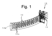
Fig. 1 is a schematic perspective view showing the configuration of a first exemplary embodiment of the vehicle lamp according to the present invention; -
Fig. 2 is a schematic plan view of the vehicle lamp ofFig. 1 ; -
Fig. 3 is a schematic front view of the vehicle lamp ofFig. 1 ; -
Fig. 4 is a schematic side view of the vehicle lamp ofFig. 1 ; -
Fig. 5 is a schematic perspective view of a light source unit in the vehicle lamp ofFig. 1 ; -
Fig. 6 is an exploded perspective view showing the configuration of the light source unit ofFig. 5 ; -
Fig. 7 is a schematic perspective view showing the state of light reflection by reflecting mirrors in the light source unit ofFig. 5 ; -
Fig. 8 is a partially enlarged front view of a light outlet pertaining to each individual LED light source in the vehicle lamp ofFig. 1 ; -
Fig. 9 is a schematic perspective view showing the configuration of a second exemplary embodiment of the vehicle lamp according to the present invention; -
Fig. 10 is a schematic plan view of the vehicle lamp ofFig. 9 ; -
Fig. 11 is a schematic front view of the vehicle lamp ofFig. 9 ; and -
Fig. 12 is a schematic side view of the vehicle lamp ofFig. 9 . - A description will now be given of preferred exemplary embodiment in accordance with the presently disclosed subject matter with reference to
Figs. 1 to 12 . - Note that in the following exemplary embodiments the vertical, horizontal, front-to-rear directions and the like are appropriately set on the basis of the respective referred drawings.
-
Figs. 1 and4 show the configuration of a first exemplary embodiment of the vehicle lamp according to the present invention. - In
Figs. 1 to 4 , thevehicle lamp 10 is a signal lamp such as a car position lamp, and can include a light source unit 11 and alight guide lens 12. - As shown in
Figs. 5 and 6 , the light source unit 11 can be composed of at least one (one, in the shown example)LED light source 21 and a pair offitting members - The
LED light source 21 can be a commercially available general-purpose LED light source. As shown inFig. 6 , theLED light source 21 is configured as a generally square package of so-called high output type, having a distribution control lens for giving directivity in front of the LED chip. - It should be appreciated that the
LED light source 21 may be a typical LED light source of bullet type. - The
LED light source 21 can be mounted on a metal circuit board 21a. Through this metal circuit board 21a, a drive voltage is applied as appropriate for lighting. - As shown in
Fig. 6 , thefitting members mirrors mirrors LED light source 21, respectively. - The
fitting members - The reflecting mirrors 24, 25, 26, and 27 are formed on respective inner surfaces of the
fitting members - Here, considering the direction of releasing the
fitting members fitting member 22 shall have the first reflectingmirror 24 and the fourth reflectingmirror 27. Thefitting member 23 shall have the third reflectingmirror 26 and the second reflectingmirror 25. - As shown by the arrows in
Fig. 6 , thesefitting members - After this assembly, the metal circuit board 21a having the foregoing
LED light source 21 mounted thereon is positioned to a predetermined location on the back of thefitting members - As a result, the respective
fitting members LED light source 21 as alight outlet 28 of horizontally-long slit shape. Thefitting members - Next, the
individual reflecting mirrors 24 to 27 will be described in detail with reference toFig. 7 . - Initially, the first reflecting
mirror 24 can be made of a plane mirror (or a convex or concave mirror having a large curvature), for example. Its reflecting surface is opposed to the light-emitting surface of the correspondingLED light source 21. - The first reflecting
mirror 24 is arranged in an emission area in front of theLED light source 21 in the direction of the optical axis (the direction of the arrow A) excluding the center section about the optical axis. Specifically, the first reflectingmirror 24 is arranged obliquely toward the front from one side, or the left inFig. 7 , to the right side at an angle of approximately 45°, for example, and slightly downward at 1° to 30°, for example. At the same time, the first reflectingmirror 24 is arranged across an area wider than the width of theLED light source 21 so as to correspond to a top section of one third the vertical width when the light-emitting surface of theLED light source 21 is vertically divided into three. - The first reflecting
mirror 24 is thus configured to reflect part of the light emitted from the LEDlight source 21 to one direction (in the shown example, to the right side) with respect to the foregoing center section. - The third reflecting
mirror 26 can be made of a plane mirror (or a convex or concave mirror having a large curvature), for example. Its reflecting surface is directed in the direction of light projection, and opposed to the reflecting surface of the first reflectingmirror 24. - The third reflecting
mirror 26 is arranged generally in parallel with the first reflectingmirror 24, on one side from the first reflecting mirror with respect to the optical axis. Specifically, the third reflectingmirror 26 is arranged in front of the correspondingLED light source 21 in parallel with this first reflectingmirror 24, i.e., obliquely toward the front from one side (the left inFig. 7 ) to the other side (right side) at an angle of approximately 45°, for example, like the first reflectingmirror 24 and slightly upward at 1° to 30°, for example, so as to correspond to the center section of one third the vertical width when the light-emitting surface of theLED light source 21 is vertically divided into three. - The third reflecting
mirror 26 is thus configured to reflect the light from the first reflectingmirror 24 forward in the direction of light projection parallel to the optical axis. - In the meantime, the second reflecting
mirror 25 and the fourth reflectingmirror 27 are formed in a configuration and arrangement rotationally symmetrical to the first reflectingmirror 24 and the third reflectingmirror 26 as described above with respect to the optical axis of theLED light source 21, i.e., as rotated 180° about the optical axis. - Consequently, when one
light outlet 28 is viewed from the front, as shown inFig. 8 , the third reflectingmirror 26 and the fourth reflectingmirror 27 fall on both sides of theLED light source 21 in the horizontally-long light outlet 28, respectively, thereby functioning as respective light-emitting parts. - It should be noted that, although the
light outlet 28 of the light source unit 11 is arranged so as to be horizontally long inFigs. 5 to 8 , in thevehicle lamp 10 ofFigs. 1 to 4 , thelight outlet 28 is arranged vertically long. - Next, the
light guide lens 12 will be described. Thelight guide lens 12 is made of a translucent material in the form of thin plate. It is arranged with oneend 12a of thin plate shape opposed to the vertically-arrangedlight outlet 28 of the light source unit 11 so as to match it along the lengthwise direction. - Here, the one
end 12a of thelight guide lens 12 is designed to be greater than thelight outlet 28 of the light source unit 11, such as 12 mm or more in vertical dimension and 4 mm or more in horizontal dimension (thickness). - The
light guide lens 12 is also formed so that its end faces excluding the oneend 12a, the incident surface, or namely theother end 12b and the top and bottom ends (corresponding to the other end faces) in the drawing are cut away obliquely 45° into slopes at the curved inside, thereby forming a trapezoidal section on the whole. - Furthermore, the
light guide lens 12 is shaped to curve to one side (the left inFig. 2 ) along the longitudinal direction from the oneend 12a to theother end 12b. - As a result, light incident on the one
end 12a of thelight guide lens 12 repeats total reflection on the sides of thelight guide lens 12 while traveling toward theother end 12b. - The
light guide lens 12 has, in its curved inside, a plurality ofrecesses 12c which are arranged in line in the longitudinal direction. In the shown example, therecesses 12c each can have a depth of 1 mm or more. - As shown in
Fig. 2 , theserecesses 12c are made of generally perpendicular surfaces of minimum draft angles for molding. As will be detailed inFig. 4 , vertically long recesses and short recesses are formed alternately. - The
recesses 12c are thereby formed to increase in depth gradually toward theother end 12b, giving some accent to the appearance design of thelight guide lens 12. - The
light guide lens 12 is also formed so that the curved outside surface has a curvature in the vertical direction (widthwise curvature). This gives thelight guide lens 12 a solid look in appearance. - The
vehicle lamp 10 according to the exemplary embodiment of the present invention is configured as described above. Hereinafter, a description will be given of the state of light emission from the light source unit and the light guiding state of light by means of the light guide lens.Figs. 5 to 8 are referred to as regard to the light source unit whileFigs. 1 to 4 are referred to as regard to the light guide lens. The directions are determined on the basis of the state as shown in each drawing. - Of the light emitted from the LED
light source 21 of the light source unit 11, light L1 that is emitted from the section of one third the vertical width at the center (emission center), when the light-emitting surface is vertically divided into three, is simply projected forward (seeFig. 7 ). - Meanwhile, light L2 that is emitted from the top section of the light-emitting surface having one third the vertical width, out of the light emitted from the LED
light source 21, is incident on the first reflectingmirror 24, is reflected to one side (right side in the shown example) slightly downward, and travels toward the third reflectingmirror 26. - The light L2 incident on the third reflecting
mirror 26 is generally horizontally reflected toward the front by this third reflectingmirror 26 for forward projection. - Moreover, light L3 emitted from the bottom section of the light-emitting surface having one third the vertical width is incident on the second reflecting
mirror 25, is reflected to the other side (left side in the shown example) slightly downward, and travels toward the fourth reflectingmirror 27. - The light L3 incident on the fourth reflecting
mirror 27 is generally horizontally reflected toward the front by this fourth reflectingmirror 27 for forward projection. - Here, the light from the top one-third section of the light-emitting surface of the
LED light source 21 is reflected twice by the first reflectingmirror 24 and the third reflectingmirror 26, and is thus projected forward as shifted to one side (right side in the shown example) in the center area of one-third height of the light-emitting surface of theLED light source 21. - Moreover, the light from the bottom one-third area of the light-emitting surface of the
LED light source 21 is reflected twice by the second reflectingmirror 25 and the fourth reflectingmirror 27, and is thus projected forward as shifted to the other side (left side in the shown example) in the center area of one-third height of the light-emitting surface of theLED light source 21. - Consequently, as shown in
Fig. 8 , the light emitted from each area of theLED light source 21 falls on the center one-third area of the light-emitting surface of theLED light source 21. Namely, the vertical width of the light-emitting surface corresponds to approximately one third the vertical width of the light-emitting surface of theLED light source 21, thereby providing a light-emitting surface of so-called narrow width. - For example, when using a ϕ4.5-mm general-purpose LED light source as the
LED light source 21, the light outlet may have a vertical width of 1.5 mm and a horizontal width of approximately 13.5 mm. - When the light source unit 11 as described above is installed in the vehicle light, it is arranged vertically long. Then, the vertically-long narrow light emitted from the light source unit 11 is incident on the one
end 12a of thelight guide lens 12 and is guided toward theother end 12b with total reflection at both side surfaces of thelight guide lens 12. - In this process, light that enters the interiors of the
recesses 12c on the way is totally reflected by the perpendicular surfaces of therecesses 12c and emitted sideways from the curved outside surface of thelight guide lens 12. - Here, the
respective recesses 12c are formed to increase in depth gradually toward theother end 12b, so that the light beams emitted outside from therespective recesses 12c have generally uniform intensities. - Moreover, light that is not incident on the
recesses 12c on the way is totally reflected by the tiltedother end 12b of thelight guide lens 12 and similarly emitted toward the front from the curved outside surface of thelight guide lens 12. - Furthermore, light that is incident on the top and bottom ends of the
light guide lens 12 on the way is totally reflected by these tilted top and bottom ends and emitted sideways. - In this way, according to the
vehicle lamp 10 of the exemplary embodiment of the present invention, the vertically-long narrow light emitted from the light source unit 11 is guided to curve to the direction of light emission along thelight guide lens 12, so that a part of it is totally reflected by therecesses 12c and the top and bottom ends and emitted sideways while the other part is totally reflected by theother end 12b and emitted toward the front. - Consequently, when the
light guide lens 12 described above is arranged to wrap around the fender area of a car body, it is possible to make the entire curved outside surface of thelight guide lens 12 emit light by using the light source unit 11 which is located behind the oneend 12a of thelight guide lens 12. - Here, since the
light guide lens 12 has the low-profile configuration (thin plate-like shape), it can be arranged along near the surface of the fender area of the car body. Furthermore, the light source unit 11 has the vertically-long light-emitting surface of narrow width, and thus requires an extremely small installation space inside the fender area of the car body. This can suppress interference with others such as a headlamp effectively, and increases layout and design flexibilities. - Moreover, since the
light guide lens 12 leaves space inside its curved portion, it is possible to install other lamps and the like in this inside space. - In this case, light emitted from the other lamps can also be passed through the
light guide lens 12 and projected forward in the direction of light projection. This makes it possible to configure a small-sized lamp of innovative design. -
Figs. 9 through 12 show the configuration of a second exemplary embodiment of the vehicle lamp according to the present invention. Thevehicle lamp 30 can include alight source unit 31 and alight guide lens 32. - Here, the
light source unit 31 has the same configuration as that of the light source unit 11 in thevehicle lamp 10 shown inFigs. 5 to 8 , with the only difference in that thelight outlet 28 is situated horizontally long. - The
light guide lens 32 is vertically thinly made of a translucent material. One end 32a of thelens 32 is arranged to be opposed to the horizontally-arranged light outlet (not shown) of thelight source unit 31. - Here, the end 32a of the
light guide lens 32 may be designed to be greater than thelight outlet 28 of thelight source unit 31 both vertically and horizontally, such as 4 mm or more in vertical dimension (thickness). - The
light guide lens 32 is also shaped to curve generally to one side (the left inFig. 10 ) along the longitudinal direction from the one end 32a to theother end 32b. More specifically, as shown inFig. 10 , the outside surface is formed as a prism cut area of step-like configuration at intervals of 3 mm or less, i.e., by combining flat surfaces perpendicular to the optical axis of thelight source unit 31 and flat surfaces parallel to the optical axis. - Meanwhile, the curved inner end of the
light guide lens 32 is formed to extend obliquely with respect to the optical axis so that it totally reflects light from thelight source unit 31. - According to the
vehicle lamp 30 of such configuration, the horizontally-long narrow light emitted from thelight source unit 31 enters thelight guide lens 32 from the one end 32a and is guided toward theother end 32b with total reflection at both side surfaces of thelight guide lens 32. - In this process, light that is incident on the step-like outside surface on the way is transmitted through the flat surfaces of this step-like prism cut area, perpendicular to the optical axis, and projected toward the front. Light that is incident on the surfaces parallel to the optical axis is totally reflected.
- Moreover, light that is incident on the inside surface on the way is totally reflected by this obliquely-extending inside surface, impinges the step-like prism cut area of the outer side at large angles with respect to the optical axis, and is emitted sideways.
- As a result, the outside surface having the prism cut area emits light.
- When the lamp is off, on the other hand, light that enters the interior of the
light guide lens 32 from outside is reflected by thelight guide lens 32 of flat shape and the prism cut area of step-like shape and is emitted outside again, thereby providing a crystalline-looking appearance. - In the
vehicle lamps light source units 11 and 31 each have a singleLED light source 21. This is not restrictive, however, and a plurality ofLED light sources 21 may be arranged in line along the direction of narrow width, i.e., vertically or horizontally. A plurality oflight guide lenses LED light sources 21. - Moreover, in the
vehicle lamps light source units 11 and 31 are arranged with their light outlet vertically long or horizontally long. This is not restrictive, however, and they may obviously be arranged so that the light outlet extends obliquely. - The oblique arrangement of the light source configuration of narrow width can thus provide even more innovative designs.
- Furthermore, in the
vehicle lamps LED light source 21 is used as the light source. This is not restrictive, however, and it is understood that other types of light-emitting devices and other types of lamps may also be used as the light source. - The present invention has dealt with the exemplary embodiments where it is simply applied to a vehicle lamp such as a position lamp. This is not restrictive, however, and it may be applied to various signal lamps and other vehicle lamps, including tail lamps, stop lamps, center high-mount stop lamps, backup lamps, front turn lamps, rear turn lamps, and side marker lamps.
- As above, according to the present invention, it is possible to provide a truly excellent vehicle lamp which is configured so that it can suppress dimensions in the depth direction and provide a wide light-emitting area with a simple configuration, and has a light-emitting surface of wraparound configuration with impressive appearance for excellent beauty.
Claims (7)
- A vehicle lamp (10), characterized by:a light source unit (11) including
at least one light source (21), and
a converting part (22) including:a pair of primary reflecting mirrors (24, 25) configured to reflect part of light emitted from the light source (21) to respective predetermined directions with respect to a center section of an emission area of the light source (21) about an optical axis thereof, the primary reflecting mirrors (24, 25) being arranged in the emission area excluding the center section; anda pair of secondary reflecting mirrors (26, 27) configured to reflect light from the primary reflecting mirrors (24, 25) into a direction of light projection parallel to the optical axis, the secondary reflecting mirrors (26, 27) being arranged generally in parallel with the respective primary reflecting mirrors (24, 25), on the respective predetermined direction sides from the primary reflecting mirrors (24, 25) with respect to the optical axis, the converting part (22) being configured to convert light emitted from the light source to light having a predetermined narrow width, the conversion part (22) having an emission area for emitting the converted light; anda light guide lens (12) includingone end face (12a) having a shape corresponding to the shape of the emission area of the conversion part (22), serving as an incident surface,a thin plate-like light guiding portion (12) configured to guide the incident light, andanother end face (12b) being a farthest part of the light guiding portion (12) away from the incident surface (12a), the light guide lens (12) having a thin plate-like configuration, the light guide lens (12) guiding the incident light from the incident surface (12a) toward the other end face (12b) and emitting the guided light from a predetermined surface thereof on the way. - The vehicle lamp (10) according to claim 1, characterized in that the thin plate-like light guiding portion (12) has a wide width side and a narrow width side, the predetermined surface from which the guided light is emitted being the wide width side.
- The vehicle lamp (30) according to claim 1, characterized in that the thin plate-like light guiding portion (32) has a wide width side and a narrow width side, the predetermined surface from which the guided light is emitted being the narrow width side.
- The vehicle lamp according to any one of claims 1 to 3, characterized in that the thin plate-like light guiding portion (12, 32) of the light guide lens extends in a direction of emission of light from the light source (11, 31) and is formed in a curved shape with respect to a direction orthogonal to the optical axis.
- The vehicle lamp according to claim 4, characterized in that the thin plate-like light guiding portion (12) of the light guide lens has a plurality of thickness changing portions (12c) in a surface on a side different from the predetermined surface for emitting light; and
the thickness changing portions (12c) are formed to increase in thickness gradually from the light-source side so as to correspond to the curved shape. - The vehicle lamp according to claim 5, characterized in that the other end face (12b) and end faces located along edges of the predetermined surface for emitting light of the light guiding portion (12) of the light guide lens excluding the incident surface (12a) are tilted with respect to the predetermined surface at a predetermined angle.
- The vehicle lamp according to claim 6, characterized in that the other end face (12b) and the end faces of the light guiding portion (12) of the light guide lens are tilted by approximately 45° with respect to the predetermined surface for emitting light.
Applications Claiming Priority (1)
| Application Number | Priority Date | Filing Date | Title |
|---|---|---|---|
| JP2007065833A JP4919041B2 (en) | 2007-03-14 | 2007-03-14 | Vehicle lighting |
Publications (2)
| Publication Number | Publication Date |
|---|---|
| EP1970616A1 true EP1970616A1 (en) | 2008-09-17 |
| EP1970616B1 EP1970616B1 (en) | 2010-06-02 |
Family
ID=39493576
Family Applications (1)
| Application Number | Title | Priority Date | Filing Date |
|---|---|---|---|
| EP08004828A Expired - Fee Related EP1970616B1 (en) | 2007-03-14 | 2008-03-14 | Vehicle lamp |
Country Status (4)
| Country | Link |
|---|---|
| US (1) | US7695175B2 (en) |
| EP (1) | EP1970616B1 (en) |
| JP (1) | JP4919041B2 (en) |
| DE (1) | DE602008001392D1 (en) |
Cited By (11)
| Publication number | Priority date | Publication date | Assignee | Title |
|---|---|---|---|---|
| ITTV20090072A1 (en) * | 2009-04-17 | 2010-10-18 | Mizar Srl | LIGHTING APPLIANCE WITH REFRACTORY DEVICE LIGHT GUIDE FOR INTERIOR AND OUTDOOR FURNISHING |
| EP2378323A3 (en) * | 2010-03-31 | 2012-08-29 | Koito Manufacturing Co., Ltd. | Vehicle lamp |
| CN102650399A (en) * | 2011-02-24 | 2012-08-29 | 株式会社小糸制作所 | Vehicular lamp |
| CN102865540A (en) * | 2011-07-05 | 2013-01-09 | 株式会社小糸制作所 | Vehicle lamp |
| CN103244882A (en) * | 2012-02-07 | 2013-08-14 | 株式会社小糸制作所 | Lamp for vehicle |
| US8632232B2 (en) | 2010-03-31 | 2014-01-21 | Koito Manufacturing Co., Ltd. | Vehicular headlamp having a columnar light guide |
| EP2816276A3 (en) * | 2013-06-22 | 2015-11-25 | Volkswagen Aktiengesellschaft | Motor vehicle with a lighting device |
| US10073205B1 (en) | 2017-05-05 | 2018-09-11 | Maxzone Vehicle Lighting Corp. | Optical module of vehicle light and light guide |
| CN110043870A (en) * | 2019-04-22 | 2019-07-23 | 大茂伟瑞柯车灯有限公司 | A kind of low cost heavy wall guide structure |
| EP2098774B1 (en) * | 2008-03-03 | 2020-07-08 | Valeo Vision | Optical system with main function for an automobile |
| CN114593397A (en) * | 2021-03-31 | 2022-06-07 | 领为视觉智能科技(宁波)有限公司 | Flat light guide for car lamp wide light emitting surface signal lamp and application |
Families Citing this family (28)
| Publication number | Priority date | Publication date | Assignee | Title |
|---|---|---|---|---|
| JP2009218076A (en) * | 2008-03-10 | 2009-09-24 | Koito Mfg Co Ltd | Vehicular lighting fixture |
| JP5603571B2 (en) * | 2009-06-05 | 2014-10-08 | 株式会社小糸製作所 | Vehicle lighting |
| US8485704B2 (en) * | 2009-10-14 | 2013-07-16 | Koito Manufacturing Co., Ltd. | Lamp unit and vehicle lamp |
| DE102009052339A1 (en) * | 2009-11-03 | 2011-05-05 | Automotive Lighting Reutlingen Gmbh | Lighting device for a motor vehicle |
| EP2325046B1 (en) * | 2009-11-17 | 2016-03-02 | SMR Patents S.à.r.l. | Method to assembly a turn signal indicator module and turn signal indicator sub-module |
| JP2011216279A (en) * | 2010-03-31 | 2011-10-27 | Koito Mfg Co Ltd | Lamp fitting for vehicle |
| JP5553214B2 (en) * | 2010-05-24 | 2014-07-16 | スタンレー電気株式会社 | Vehicle lighting |
| JP5675465B2 (en) * | 2011-03-31 | 2015-02-25 | 株式会社小糸製作所 | Vehicle lighting |
| DE102011016401A1 (en) * | 2011-04-08 | 2012-10-11 | GM Global Technology Operations LLC (n. d. Gesetzen des Staates Delaware) | Lighting device for a motor vehicle and motor vehicle |
| JP5261543B2 (en) * | 2011-06-30 | 2013-08-14 | シャープ株式会社 | Laser beam utilization apparatus and vehicle headlamp |
| JP5930630B2 (en) * | 2011-08-24 | 2016-06-08 | スタンレー電気株式会社 | Lamp |
| JP5779045B2 (en) * | 2011-08-25 | 2015-09-16 | スタンレー電気株式会社 | Vehicle lighting |
| DE102011085385A1 (en) * | 2011-10-28 | 2013-05-02 | Bayerische Motoren Werke Aktiengesellschaft | Lighting device for a motor vehicle |
| JP2013109942A (en) * | 2011-11-21 | 2013-06-06 | Koito Mfg Co Ltd | Vehicular lamp |
| US20130265791A1 (en) | 2012-04-10 | 2013-10-10 | Ford Global Technologies, Llc | Vehicle light assembly with photon recycling |
| WO2014105408A2 (en) | 2012-12-28 | 2014-07-03 | 3M Innovative Properties Company | Hybrid tailight article |
| US9464785B2 (en) | 2013-01-08 | 2016-10-11 | Ford Global Technologies, Llc | Vehicular light guides and assemblies with uniform illumination |
| JP5945238B2 (en) * | 2013-03-11 | 2016-07-05 | 株式会社豊田自動織機 | Vehicle lamp and vehicle rear panel |
| JP6085276B2 (en) * | 2014-09-29 | 2017-02-22 | 本田技研工業株式会社 | Lamp |
| JP6479412B2 (en) * | 2014-10-24 | 2019-03-06 | スタンレー電気株式会社 | Vehicle lighting |
| JP2017033777A (en) * | 2015-08-03 | 2017-02-09 | スタンレー電気株式会社 | Light guide body and vehicular lighting fixture including the same |
| KR101811433B1 (en) * | 2016-06-09 | 2017-12-21 | 현대모비스 주식회사 | Lighting apparatus for an automobile |
| US10711971B2 (en) * | 2016-10-14 | 2020-07-14 | Lumileds Llc | Vehicle light assembly comprising flexible lighting strip |
| JP6744196B2 (en) * | 2016-10-31 | 2020-08-19 | スタンレー電気株式会社 | Vehicle lighting |
| CN106931381A (en) * | 2017-03-02 | 2017-07-07 | 上海小糸车灯有限公司 | A kind of novel optical system for realizing cab signal lamp |
| GB2585687B (en) | 2019-07-11 | 2021-08-18 | Dyson Technology Ltd | Vehicle lamps |
| JP2022022651A (en) * | 2020-06-30 | 2022-02-07 | 市光工業株式会社 | Vehicular light guide body and vehicular lighting fixture |
| US11441754B1 (en) * | 2021-08-19 | 2022-09-13 | Ford Global Technologies, Llc | Vehicle lighting assembly with reflector system and light emitter |
Citations (3)
| Publication number | Priority date | Publication date | Assignee | Title |
|---|---|---|---|---|
| US6305813B1 (en) | 1999-08-11 | 2001-10-23 | North American Lighting, Inc. | Display device using a light guide for exterior automotive lighting |
| US20050088758A1 (en) | 2003-02-04 | 2005-04-28 | Light Prescriptions Innovators, Llc, A Delaware Limited Liability Company | Etendue-squeezing illumination optics |
| EP1677045A2 (en) | 2004-12-30 | 2006-07-05 | Osram Opto Semiconductors GmbH | Lighting device comprising a plurality of semi-conductor light sources |
Family Cites Families (14)
| Publication number | Priority date | Publication date | Assignee | Title |
|---|---|---|---|---|
| US4257084A (en) * | 1979-02-21 | 1981-03-17 | Reynolds Christopher H | Display device |
| FR2472135A1 (en) * | 1979-12-20 | 1981-06-26 | Cibie Projecteurs | PROJECTOR, IN PARTICULAR FOR MOTOR VEHICLES |
| US5365412A (en) * | 1993-01-07 | 1994-11-15 | Ford Motor Company | Low profile illuminator |
| JPH07130208A (en) * | 1993-10-29 | 1995-05-19 | Hayashi Telempu Co Ltd | Light source device for automobile |
| US5434754A (en) * | 1993-12-27 | 1995-07-18 | Ford Motor Company | Light manifold |
| US5590945A (en) * | 1995-07-26 | 1997-01-07 | Industrial Devices, Inc. | Illuminated line of light using point light source |
| US6168302B1 (en) * | 1997-12-09 | 2001-01-02 | Cooper Automotive Products, Inc. | Hybrid distributed lighting system for a vehicle |
| US6102559A (en) * | 1999-01-25 | 2000-08-15 | Ford Motor Company | Multi-function vehicle taillight system with unitary optic |
| EP1089034A1 (en) * | 1999-09-30 | 2001-04-04 | Valeo Vision | Lighting module comprising a light pipe for motor vehicle |
| JP3776658B2 (en) * | 1999-12-13 | 2006-05-17 | ローム株式会社 | Light guide plate, lighting device, and liquid crystal display device including the lighting device |
| JP4030728B2 (en) | 2001-04-25 | 2008-01-09 | 株式会社小糸製作所 | Vehicle headlamp |
| JP2004001710A (en) * | 2002-04-11 | 2004-01-08 | Iisamu:Kk | Side mirror cover, side mirror body, and lamp therefor |
| DE502004003296D1 (en) * | 2004-10-28 | 2007-05-03 | Delphi Tech Inc | vehicle light |
| JP4413764B2 (en) | 2004-12-10 | 2010-02-10 | 株式会社小糸製作所 | Vehicle lighting |
-
2007
- 2007-03-14 JP JP2007065833A patent/JP4919041B2/en not_active Expired - Fee Related
-
2008
- 2008-03-14 EP EP08004828A patent/EP1970616B1/en not_active Expired - Fee Related
- 2008-03-14 US US12/048,866 patent/US7695175B2/en not_active Expired - Fee Related
- 2008-03-14 DE DE602008001392T patent/DE602008001392D1/en active Active
Patent Citations (3)
| Publication number | Priority date | Publication date | Assignee | Title |
|---|---|---|---|---|
| US6305813B1 (en) | 1999-08-11 | 2001-10-23 | North American Lighting, Inc. | Display device using a light guide for exterior automotive lighting |
| US20050088758A1 (en) | 2003-02-04 | 2005-04-28 | Light Prescriptions Innovators, Llc, A Delaware Limited Liability Company | Etendue-squeezing illumination optics |
| EP1677045A2 (en) | 2004-12-30 | 2006-07-05 | Osram Opto Semiconductors GmbH | Lighting device comprising a plurality of semi-conductor light sources |
Cited By (16)
| Publication number | Priority date | Publication date | Assignee | Title |
|---|---|---|---|---|
| EP2098774B1 (en) * | 2008-03-03 | 2020-07-08 | Valeo Vision | Optical system with main function for an automobile |
| ITTV20090072A1 (en) * | 2009-04-17 | 2010-10-18 | Mizar Srl | LIGHTING APPLIANCE WITH REFRACTORY DEVICE LIGHT GUIDE FOR INTERIOR AND OUTDOOR FURNISHING |
| EP2378323A3 (en) * | 2010-03-31 | 2012-08-29 | Koito Manufacturing Co., Ltd. | Vehicle lamp |
| US8632232B2 (en) | 2010-03-31 | 2014-01-21 | Koito Manufacturing Co., Ltd. | Vehicular headlamp having a columnar light guide |
| CN102650399A (en) * | 2011-02-24 | 2012-08-29 | 株式会社小糸制作所 | Vehicular lamp |
| CN102865540A (en) * | 2011-07-05 | 2013-01-09 | 株式会社小糸制作所 | Vehicle lamp |
| EP2543925A3 (en) * | 2011-07-05 | 2014-01-22 | Koito Manufacturing Co., Ltd. | Vehicle lamp |
| US8708538B2 (en) | 2011-07-05 | 2014-04-29 | Koito Manufacturing Co., Ltd. | Vehicle lamp |
| CN102865540B (en) * | 2011-07-05 | 2016-03-09 | 株式会社小糸制作所 | Lamps apparatus for vehicle |
| CN103244882A (en) * | 2012-02-07 | 2013-08-14 | 株式会社小糸制作所 | Lamp for vehicle |
| EP2816276A3 (en) * | 2013-06-22 | 2015-11-25 | Volkswagen Aktiengesellschaft | Motor vehicle with a lighting device |
| EP3399227A1 (en) * | 2017-05-05 | 2018-11-07 | Depo Auto Parts Ind. Co., Ltd. | Optical module of vehicle light and light guide |
| US10073205B1 (en) | 2017-05-05 | 2018-09-11 | Maxzone Vehicle Lighting Corp. | Optical module of vehicle light and light guide |
| CN110043870A (en) * | 2019-04-22 | 2019-07-23 | 大茂伟瑞柯车灯有限公司 | A kind of low cost heavy wall guide structure |
| CN110043870B (en) * | 2019-04-22 | 2024-04-12 | 大茂伟瑞柯车灯有限公司 | Low-cost thick-wall light guide structure |
| CN114593397A (en) * | 2021-03-31 | 2022-06-07 | 领为视觉智能科技(宁波)有限公司 | Flat light guide for car lamp wide light emitting surface signal lamp and application |
Also Published As
| Publication number | Publication date |
|---|---|
| DE602008001392D1 (en) | 2010-07-15 |
| EP1970616B1 (en) | 2010-06-02 |
| US20080232127A1 (en) | 2008-09-25 |
| JP2008226739A (en) | 2008-09-25 |
| US7695175B2 (en) | 2010-04-13 |
| JP4919041B2 (en) | 2012-04-18 |
Similar Documents
| Publication | Publication Date | Title |
|---|---|---|
| EP1970616A1 (en) | Vehicle lamp | |
| EP2693105B1 (en) | Vehicle lighting unit | |
| EP2157363B1 (en) | Optical element for vehicle lamp | |
| US9506615B2 (en) | Motor vehicle headlamp having a multi-function projection module | |
| JP4937649B2 (en) | Vehicle lighting | |
| US8480266B2 (en) | Vehicle light unit and vehicle light | |
| JP5582379B2 (en) | Optical module and vehicle signal lamp | |
| US10690307B2 (en) | Optical part comprising a block with a dioptric interface forming a folder for two beams | |
| JP4663732B2 (en) | Vehicle light | |
| US7985011B2 (en) | Vehicle lamp | |
| US8231255B2 (en) | Vehicle light | |
| WO2016104111A1 (en) | Vehicular lighting tool | |
| US7527404B2 (en) | Lighting and/or signalling apparatus for a motor vehicle | |
| JP2014022313A (en) | Vehicular head lamp | |
| JP5168551B2 (en) | Projection lens for lamp, optical unit for vehicle, and lamp for vehicle | |
| CN111503591A (en) | Far and near light integrated car light module and car | |
| JP7278920B2 (en) | Light guide lens, lens assembly and vehicle lamp | |
| EP3135989A1 (en) | Vehicle light guide and vehicle lamp | |
| JP6498474B2 (en) | Vehicle lighting | |
| EP3712492B1 (en) | Lighting device for vehicle signal lamp | |
| JP7439516B2 (en) | Vehicle lights | |
| JP2016225254A (en) | Vehicular lighting fixture | |
| CN112219062B (en) | Lighting module for a motor vehicle, and lighting and/or signaling device provided with such a module | |
| JP7238605B2 (en) | Vehicle light guide and vehicle headlamp | |
| JP2021111446A (en) | Vehicular lighting fixture |
Legal Events
| Date | Code | Title | Description |
|---|---|---|---|
| PUAI | Public reference made under article 153(3) epc to a published international application that has entered the european phase |
Free format text: ORIGINAL CODE: 0009012 |
|
| AK | Designated contracting states |
Kind code of ref document: A1 Designated state(s): AT BE BG CH CY CZ DE DK EE ES FI FR GB GR HR HU IE IS IT LI LT LU LV MC MT NL NO PL PT RO SE SI SK TR |
|
| AX | Request for extension of the european patent |
Extension state: AL BA MK RS |
|
| 17P | Request for examination filed |
Effective date: 20090115 |
|
| 17Q | First examination report despatched |
Effective date: 20090219 |
|
| AKX | Designation fees paid |
Designated state(s): DE FR GB |
|
| GRAP | Despatch of communication of intention to grant a patent |
Free format text: ORIGINAL CODE: EPIDOSNIGR1 |
|
| RIN1 | Information on inventor provided before grant (corrected) |
Inventor name: FUTAMI, TAKASHI |
|
| GRAS | Grant fee paid |
Free format text: ORIGINAL CODE: EPIDOSNIGR3 |
|
| GRAA | (expected) grant |
Free format text: ORIGINAL CODE: 0009210 |
|
| AK | Designated contracting states |
Kind code of ref document: B1 Designated state(s): DE FR GB |
|
| REG | Reference to a national code |
Ref country code: GB Ref legal event code: FG4D |
|
| REF | Corresponds to: |
Ref document number: 602008001392 Country of ref document: DE Date of ref document: 20100715 Kind code of ref document: P |
|
| PLBE | No opposition filed within time limit |
Free format text: ORIGINAL CODE: 0009261 |
|
| STAA | Information on the status of an ep patent application or granted ep patent |
Free format text: STATUS: NO OPPOSITION FILED WITHIN TIME LIMIT |
|
| 26N | No opposition filed |
Effective date: 20110303 |
|
| REG | Reference to a national code |
Ref country code: DE Ref legal event code: R097 Ref document number: 602008001392 Country of ref document: DE Effective date: 20110302 |
|
| REG | Reference to a national code |
Ref country code: FR Ref legal event code: PLFP Year of fee payment: 9 |
|
| PGFP | Annual fee paid to national office [announced via postgrant information from national office to epo] |
Ref country code: DE Payment date: 20160308 Year of fee payment: 9 |
|
| PGFP | Annual fee paid to national office [announced via postgrant information from national office to epo] |
Ref country code: FR Payment date: 20160208 Year of fee payment: 9 Ref country code: GB Payment date: 20160309 Year of fee payment: 9 |
|
| REG | Reference to a national code |
Ref country code: DE Ref legal event code: R119 Ref document number: 602008001392 Country of ref document: DE |
|
| GBPC | Gb: european patent ceased through non-payment of renewal fee |
Effective date: 20170314 |
|
| REG | Reference to a national code |
Ref country code: FR Ref legal event code: ST Effective date: 20171130 |
|
| PG25 | Lapsed in a contracting state [announced via postgrant information from national office to epo] |
Ref country code: DE Free format text: LAPSE BECAUSE OF NON-PAYMENT OF DUE FEES Effective date: 20171003 Ref country code: FR Free format text: LAPSE BECAUSE OF NON-PAYMENT OF DUE FEES Effective date: 20170331 |
|
| PG25 | Lapsed in a contracting state [announced via postgrant information from national office to epo] |
Ref country code: GB Free format text: LAPSE BECAUSE OF NON-PAYMENT OF DUE FEES Effective date: 20170314 |