EP1970271A1 - Brake system - Google Patents
Brake system Download PDFInfo
- Publication number
- EP1970271A1 EP1970271A1 EP08152610A EP08152610A EP1970271A1 EP 1970271 A1 EP1970271 A1 EP 1970271A1 EP 08152610 A EP08152610 A EP 08152610A EP 08152610 A EP08152610 A EP 08152610A EP 1970271 A1 EP1970271 A1 EP 1970271A1
- Authority
- EP
- European Patent Office
- Prior art keywords
- fluid pressure
- cylinder
- brake fluid
- brake
- slave cylinder
- Prior art date
- Legal status (The legal status is an assumption and is not a legal conclusion. Google has not performed a legal analysis and makes no representation as to the accuracy of the status listed.)
- Granted
Links
- 239000012530 fluid Substances 0.000 claims abstract description 221
- 239000002674 ointment Substances 0.000 claims 2
- 230000002159 abnormal effect Effects 0.000 abstract description 4
- 230000014759 maintenance of location Effects 0.000 description 21
- 230000007423 decrease Effects 0.000 description 12
- 238000010586 diagram Methods 0.000 description 4
- 230000003247 decreasing effect Effects 0.000 description 3
- 238000000034 method Methods 0.000 description 3
- 238000011144 upstream manufacturing Methods 0.000 description 3
- 230000005540 biological transmission Effects 0.000 description 1
- 230000001276 controlling effect Effects 0.000 description 1
- 230000000881 depressing effect Effects 0.000 description 1
- 230000000694 effects Effects 0.000 description 1
- 239000007788 liquid Substances 0.000 description 1
- 230000001105 regulatory effect Effects 0.000 description 1
Images


Classifications
-
- B—PERFORMING OPERATIONS; TRANSPORTING
- B60—VEHICLES IN GENERAL
- B60T—VEHICLE BRAKE CONTROL SYSTEMS OR PARTS THEREOF; BRAKE CONTROL SYSTEMS OR PARTS THEREOF, IN GENERAL; ARRANGEMENT OF BRAKING ELEMENTS ON VEHICLES IN GENERAL; PORTABLE DEVICES FOR PREVENTING UNWANTED MOVEMENT OF VEHICLES; VEHICLE MODIFICATIONS TO FACILITATE COOLING OF BRAKES
- B60T8/00—Arrangements for adjusting wheel-braking force to meet varying vehicular or ground-surface conditions, e.g. limiting or varying distribution of braking force
- B60T8/32—Arrangements for adjusting wheel-braking force to meet varying vehicular or ground-surface conditions, e.g. limiting or varying distribution of braking force responsive to a speed condition, e.g. acceleration or deceleration
- B60T8/34—Arrangements for adjusting wheel-braking force to meet varying vehicular or ground-surface conditions, e.g. limiting or varying distribution of braking force responsive to a speed condition, e.g. acceleration or deceleration having a fluid pressure regulator responsive to a speed condition
- B60T8/40—Arrangements for adjusting wheel-braking force to meet varying vehicular or ground-surface conditions, e.g. limiting or varying distribution of braking force responsive to a speed condition, e.g. acceleration or deceleration having a fluid pressure regulator responsive to a speed condition comprising an additional fluid circuit including fluid pressurising means for modifying the pressure of the braking fluid, e.g. including wheel driven pumps for detecting a speed condition, or pumps which are controlled by means independent of the braking system
- B60T8/4072—Systems in which a driver input signal is used as a control signal for the additional fluid circuit which is normally used for braking
- B60T8/4081—Systems with stroke simulating devices for driver input
Definitions
- the present invention relates to a brake system comprising a master cylinder that generates brake fluid pressure by a braking operation of a driver, and a slave cylinder that generates brake fluid pressure by a driving force of an electric motor that operates according to an electrical signal which is responsive to the braking operation by the driver.
- a failsafe or failure backup process for braking is perform by supplying brake fluid pressure generated by a master cylinder to the wheel cylinder via the slave cylinder.
- the predetermined time is set to be a time period required for the brake fluid pressure generated by the master cylinder to rise to the predetermined value or higher. Therefore, when the opening and closing valve, which has been closed in order to maintain the brake fluid pressure of the wheel cylinder, opens again, the master cylinder has a sufficiently increased brake fluid pressure. Thus, it is possible to reliably prevent a decrease in the brake fluid pressure of the wheel cylinder.
- the brake system further comprises a first fluid pressure sensor for detecting brake fluid pressure generated by the master cylinder, and a second fluid pressure sensor for detecting brake fluid pressure generated by the slave cylinder, wherein the slave cylinder generates brake fluid pressure so that the brake fluid pressure detected by the second fluid pressure sensor is adjusted to a level corresponding to the brake fluid pressure detected by the first fluid pressure sensor.
- the brake system further comprises a stroke simulator connected to the master cylinder through a reaction force permission valve, wherein the stroke simulator absorbs the brake fluid pressure generated by the master cylinder by opening the reaction force permission valve when the slave cylinder operates normally; and the brake fluid pressure generated by the master cylinder is supplied to the wheel cylinder by closing the reaction force permission valve when the slave cylinder does not operate normally.
- the stroke simulator is connected to the master cylinder through the reaction force permission valve, and the brake fluid pressure generated by the master cylinder is absorbed by the stroke simulator when the reaction force permission valve is opened under normal operation of the slave cylinder. Therefore, it is possible to provide a pedal feeling equivalent to that provided by the brake fluid pressure generated by the master cylinder, thereby eliminating an uncomfortable feeling to the driver. Further, because the brake fluid pressure generated by the master cylinder is supplied to the wheel cylinder without being absorbed by the stroke simulator when the reaction force permission valve is closed when the slave cylinder does not operate normally, it is possible to perform braking by the brake fluid pressure generated by the master cylinder without any problem even when the slave cylinder becomes inoperative.
- Fluid pressure retention valves 31A, 31B and regulator valves 61 of exemplary embodiments of the invention disclosed herein correspond to the opening and closing valves of the present invention.
- FIGS. 5 and 6 show a second exemplary embodiment of the present invention wherein
- FIG. 5 is a fluid pressure circuit diagram of a vehicle brake system under normal operating conditions.
- FIG. 6 is a fluid pressure circuit diagram corresponding to FIG. 5 under abnormal operating conditions.
- FIGS. 1 to 4B A first exemplary embodiment of the present invention will be described with reference to FIGS. 1 to 4B .
- a shutoff valve 22A which is a normally open solenoid valve, is provided between the fluid passages Pa and Pb.
- a shutoff valve 22B which is a normally open solenoid valve, is provided between the fluid passages Qa and Qb.
- a slave cylinder 23 is provided between the fluid passages Pb, Qb and the fluid passages Pc, Qc.
- a reaction force permission valve 25 which is a normally closed solenoid valve, is connected between a fluid passage Ra branching from the fluid passage Qa and a fluid passage Rb.
- a stroke simulator 26 is connected to the fluid passages Ra and Rb via the reaction force permission valve 25.
- the stroke simulator 26 has a cylinder 27 and a piston 29 slidably fitted in the cylinder 27 while being urged by a spring 28.
- An actuator 51 of the slave cylinder 23 has a drive bevel gear 53 provided on the rotating shaft of an electric motor 52, a follower bevel gear 54 meshing with the drive bevel gear 53, and a ball screw mechanism 55 operated by the follower bevel gear 54.
- a sleeve 58 is rotatably supported in an actuator housing 56 via a pair of ball bearings 57.
- An output shaft 59 is coaxially arranged on an inner periphery of the sleeve 58.
- the follower bevel gear 54 is arranged on an outer periphery of the sleeve 58.
- a pair of pistons 38A and 38B urged in a retreat direction by a pair of return springs 37A and 37B are slidably disposed in a cylinder body 36 of the slave cylinder 23.
- a pair of second fluid pressure chambers 39A and 39B are defined on the front faces of the pistons 38A and 38B, respectively.
- a front end of the output shaft 59 abuts on a rear end of the rear piston 38A.
- One of the second fluid pressure chamber 39A communicates with the fluid passages Pb, Pc via ports 40A, 41A, while the other second fluid pressure chamber 39B communicates with the fluid passages Qb, Qc through ports 40B, 41B.
- the operation of the actuator 51 for the slave cylinder 23 is controlled so that the brake fluid pressure generated by the slave cylinder 23 and detected by the fluid pressure sensor Sb provided in the fluid passage Qc has a value corresponding to the brake fluid pressure generated by the master cylinder 11 and detected by the fluid pressure sensor Sa provided in the fluid passage Qa, thereby generating the braking force in the disc brake devices 14, 15, 18 and 19 according to the pushing force applied to the brake pedal 12 by the driver.
- the brake fluid pressure generated in the first fluid pressure chambers 13A and 13B of the master cylinder 11 passes the shutoff valves 22A and 22B, the second fluid pressure chambers 39A and 39B of the slave cylinder 23 and the fluid pressure retention valves 31A and 31B, without being absorbed by the stroke simulator 26, and operates the wheel cylinders 16, 17, 20 and 21 of the disc brake devices 14, 15, 18 and 19, respectively, for braking the vehicle wheels, thus generating the braking force without any problem.
- the fluid pressure retention valves 31A, 31B are closed from that point of time until a predetermined time Tc elapses.
- the predetermined time Tc is set beforehand as a time period which elapses until the brake fluid pressure generated by the master cylinder 11 (the fluid pressure of the fluid passage Qa detected by the fluid pressure sensor Sa) increases to a predetermined value or more.
- the second exemplary embodiment has no fluid pressure retention valves such as the fluid pressure retention valves 31A, 31B of the brake according to the first exemplary embodiment, and their function is provided instead by regulator valves 61, 61, which will be described later.
- Suction valves 63, 63 comprising normally closed solenoid valves are arranged in the fluid passages Pf, Qf which branch from a position between the check valves 45, 45 and the check valves 62, 62 and leads to the liquid passages Pc, Qc upstream of the regulator valves 61, 61.
- a pressure reducing operation is performed to release the brake fluid pressure in the wheel cylinder by opening the out-valve 44 to the reservoir 43 such that the transmission of the brake fluid pressure from the slave cylinder 23 is shut off by closing the in-valve 42 communicating with the wheel cylinder; and a pressure maintaining operation is subsequently performed to maintain the brake fluid pressure in the wheel cylinder by closing the out-valve 44, thereby reducing the braking force to avoid locking of the vehicle wheel.
- shutoff valves 22A and 22B are magnetized so as to be closed, thereby preventing a fluid pressure fluctuation associated with the operation of the ABS 24 from being transmitted as a kickback from the master cylinder 11 to the brake pedal 12.
- the communication between the slave cylinder 23 and the wheel cylinders 16, 17; 20, 21 is temporarily shut off by closing the regulator valves 61, 61 in FIG. 6 , thereby preventing a decrease in the brake fluid pressure of the wheel cylinders 16, 17; 20, 21.
- the regulator valves 61, 61 are opened again, thereby operating the wheel cylinders 16, 17; 20, 21 by the brake fluid pressure generated by the master cylinder 11.
- the stroke simulator 26 is separated from the master cylinder 11 by closing the reaction force permission valve 25 under abnormal operating conditions.
Landscapes
- Physics & Mathematics (AREA)
- Fluid Mechanics (AREA)
- Engineering & Computer Science (AREA)
- Transportation (AREA)
- Mechanical Engineering (AREA)
- Regulating Braking Force (AREA)
- Valves And Accessory Devices For Braking Systems (AREA)
Abstract
Description
- The present invention relates to a brake system comprising a master cylinder that generates brake fluid pressure by a braking operation of a driver, and a slave cylinder that generates brake fluid pressure by a driving force of an electric motor that operates according to an electrical signal which is responsive to the braking operation by the driver.
- Japanese Patent Application Laid-open No.
2005-343366 - If a problem occurs that renders the electric motor inoperative when an electric brake force generator (slave cylinder) of the BBW brake system is generating brake fluid pressure to operate a wheel cylinder, a failsafe or failure backup process for braking is perform by supplying brake fluid pressure generated by a master cylinder to the wheel cylinder via the slave cylinder.
- However, at the moment when the slave cylinder becomes unable to generate a driving force for pushing a piston, the piston is pushed back by brake fluid pressure within the wheel cylinder. Therefore, there is a problem that the brake fluid pressure within the wheel cylinder suddenly decreases until the brake fluid pressure supplied from the master cylinder is built up.
- The present invention has been made in view of the above circumstances, and it is an object thereof to prevent a sudden decrease in brake fluid pressure of a wheel cylinder when a slave cylinder fails during braking.
- To achieve the above object, according to a first aspect of the present invention, there is provided a brake system comprising: a master cylinder that generates brake fluid pressure by a braking operation of a driver; an electric motor-driven slave cylinder that generates brake fluid pressure according to an electrical signal which is based on the braking operation of the driver; a wheel cylinder that brakes a wheel by the brake fluid pressure of the master cylinder or the slave cylinder; the brake fluid pressure of the slave cylinder being transmitted to the wheel cylinder when the slave cylinder operates normally, and the brake fluid pressure of the master cylinder being transmitted to the wheel cylinder through the slave cylinder when the slave cylinder does not operate normally; and an opening and closing valve that opens and closes a fluid passage which connects the slave cylinder to the wheel cylinder, wherein the opening and closing valve is closed for a predetermined time when a problem occurs with the slave cylinder during braking.
- With the first aspect of the present invention, if a problem occurs with the slave cylinder (e.g., it fails) when the wheel cylinder is being operated by the brake fluid pressure generated by the slave cylinder in a normal operation, the brake fluid pressure of the wheel cylinder is maintained for a predetermined time by closing the opening and closing valve provided in the fluid passage which connects the slave cylinder to the wheel cylinder. Therefore, during this predetermined time, it is possible to cause the master cylinder to build up sufficient brake fluid pressure for a backup process. Thus, a sudden decrease in the brake fluid pressure of the wheel cylinder can be prevented when braking by the slave cylinder is switched to braking by the master cylinder.
- According to a second aspect of the present invention, in addition to the first aspect, the predetermined time is a time period required for the brake fluid pressure generated by the master cylinder to rise to a predetermined value or higher.
- With the second aspect of the present invention, the predetermined time is set to be a time period required for the brake fluid pressure generated by the master cylinder to rise to the predetermined value or higher. Therefore, when the opening and closing valve, which has been closed in order to maintain the brake fluid pressure of the wheel cylinder, opens again, the master cylinder has a sufficiently increased brake fluid pressure. Thus, it is possible to reliably prevent a decrease in the brake fluid pressure of the wheel cylinder.
- According to a third aspect of the present invention, in addition to the first or second aspect, the brake system further comprises a first fluid pressure sensor for detecting brake fluid pressure generated by the master cylinder, and a second fluid pressure sensor for detecting brake fluid pressure generated by the slave cylinder, wherein the slave cylinder generates brake fluid pressure so that the brake fluid pressure detected by the second fluid pressure sensor is adjusted to a level corresponding to the brake fluid pressure detected by the first fluid pressure sensor.
- With the third aspect of the present invention, when braking is performed by the brake fluid pressure generated by the slave cylinder that operates according to an electrical signal which is responsive to the braking operation of the driver, the first fluid pressure sensor detects the brake fluid pressure generated by the master cylinder, the second fluid sensor detects the brake fluid pressure generated by the slave cylinder, and the slave cylinder generates brake fluid pressure so that the brake fluid pressure detected by the second fluid pressure sensor is adjusted to a level corresponding to the brake fluid pressure detected by the first fluid pressure sensor. Therefore, it is possible to cause the slave cylinder to generate brake fluid pressure corresponding to the operational amount of the master cylinder, thereby providing a braking force which the driver requires.
- According to a fourth aspect of the present invention, in addition to the first or second aspect, the brake system further comprises a stroke simulator connected to the master cylinder through a reaction force permission valve, wherein the stroke simulator absorbs the brake fluid pressure generated by the master cylinder by opening the reaction force permission valve when the slave cylinder operates normally; and the brake fluid pressure generated by the master cylinder is supplied to the wheel cylinder by closing the reaction force permission valve when the slave cylinder does not operate normally.
- With the fourth aspect of the present invention, the stroke simulator is connected to the master cylinder through the reaction force permission valve, and the brake fluid pressure generated by the master cylinder is absorbed by the stroke simulator when the reaction force permission valve is opened under normal operation of the slave cylinder. Therefore, it is possible to provide a pedal feeling equivalent to that provided by the brake fluid pressure generated by the master cylinder, thereby eliminating an uncomfortable feeling to the driver. Further, because the brake fluid pressure generated by the master cylinder is supplied to the wheel cylinder without being absorbed by the stroke simulator when the reaction force permission valve is closed when the slave cylinder does not operate normally, it is possible to perform braking by the brake fluid pressure generated by the master cylinder without any problem even when the slave cylinder becomes inoperative.
- Fluid
pressure retention valves regulator valves 61 of exemplary embodiments of the invention disclosed herein correspond to the opening and closing valves of the present invention. - The above-mentioned object, other objects, characteristics, and advantages of the present invention will become apparent from the preferred embodiments, which will be described in detail below with reference to the attached drawings.
-
-
FIGS. 1 to 4B show a first exemplary embodiment of the present invention wherein -
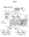
FIG. 1 is a fluid pressure circuit diagram of a vehicle brake system under normal operating conditions; -
FIG. 2 is a fluid pressure circuit diagram corresponding toFIG. 1 under abnormal operating conditions; -
FIG. 3 is a flowchart for explaining operation when the slave cylinder is not operating normally, e.g., when it fails; -
FIG. 4A is a time chart for explaining operation of a conventional brake system when the slave cylinder has failed (prior art); and -
FIG. 4B is a time chart for explaining operation of the embodiment ofFIG. 1 when the slave cylinder has failed. -
FIGS. 5 and6 show a second exemplary embodiment of the present invention wherein -
FIG. 5 is a fluid pressure circuit diagram of a vehicle brake system under normal operating conditions; and -
FIG. 6 is a fluid pressure circuit diagram corresponding toFIG. 5 under abnormal operating conditions. - A first exemplary embodiment of the present invention will be described with reference to
FIGS. 1 to 4B . - As shown in
FIG. 1 , atandem master cylinder 11 has two firstfluid pressure chambers brake pedal 12 by a driver depressing thebrake pedal 12. One of the firstfluid pressure chamber 13A is connected towheel cylinders 16 and 17 ofdisc brake devices fluid pressure chamber 13B is connected towheel cylinders disc brake devices - A
shutoff valve 22A, which is a normally open solenoid valve, is provided between the fluid passages Pa and Pb. Ashutoff valve 22B, which is a normally open solenoid valve, is provided between the fluid passages Qa and Qb. Aslave cylinder 23 is provided between the fluid passages Pb, Qb and the fluid passages Pc, Qc. - A reaction
force permission valve 25, which is a normally closed solenoid valve, is connected between a fluid passage Ra branching from the fluid passage Qa and a fluid passage Rb. Astroke simulator 26 is connected to the fluid passages Ra and Rb via the reactionforce permission valve 25. Thestroke simulator 26 has acylinder 27 and apiston 29 slidably fitted in thecylinder 27 while being urged by aspring 28. Afluid chamber 30, formed on the side of thepiston 29 opposite from thespring 28, communicates with the fluid passage Rb. - An
actuator 51 of theslave cylinder 23 has adrive bevel gear 53 provided on the rotating shaft of anelectric motor 52, afollower bevel gear 54 meshing with thedrive bevel gear 53, and aball screw mechanism 55 operated by thefollower bevel gear 54. Asleeve 58 is rotatably supported in anactuator housing 56 via a pair ofball bearings 57. Anoutput shaft 59 is coaxially arranged on an inner periphery of thesleeve 58. Thefollower bevel gear 54 is arranged on an outer periphery of thesleeve 58. - A pair of
pistons return springs cylinder body 36 of theslave cylinder 23. A pair of secondfluid pressure chambers pistons output shaft 59 abuts on a rear end of therear piston 38A. One of the secondfluid pressure chamber 39A communicates with the fluid passages Pb, Pc viaports fluid pressure chamber 39B communicates with the fluid passages Qb, Qc throughports - Further, a fluid
pressure retention valve 31A, which is a normally open solenoid valve, is arranged between the fluid passage Pc and the fluid passages Pd and Pe, and a fluidpressure retention valve 31B, which is a normally open solenoid valve, is arranged between the fluid passage Qc and the fluid passages Qd and Qe. - The operation of the first exemplary embodiment of the present invention having the above-described arrangement will now be described.
- When the system is operating under normal conditions, the
shutoff valves force permission valve 25, comprising a normally closed solenoid valve, is magnetized so as to be in an open state; and the fluidpressure retention valves brake pedal 12 by the driver, theactuator 51 of theslave cylinder 23 is operated. That is, when theelectric motor 52 is driven in one direction, theoutput shaft 59 is advanced by thedrive bevel gear 53, thefollower bevel gear 54 and theball screw mechanism 55, so that the pair of thepistons output shaft 59 are advanced. Because theports pistons fluid pressure chambers wheel cylinders disc brake devices pressure retention valves - At this time, the brake fluid pressure generated in the first
fluid pressure chamber 13B of themaster cylinder 11 is transmitted to thefluid chamber 30 of thestroke simulator 26 through the opened reactionforce permission valve 25 to move thepiston 29 against thespring 28, thereby generating a pseudo pedal reaction force while permitting the stroke of thebrake pedal 12 in order to eliminate an uncomfortable feeling to the driver. - The operation of the
actuator 51 for theslave cylinder 23 is controlled so that the brake fluid pressure generated by theslave cylinder 23 and detected by the fluid pressure sensor Sb provided in the fluid passage Qc has a value corresponding to the brake fluid pressure generated by themaster cylinder 11 and detected by the fluid pressure sensor Sa provided in the fluid passage Qa, thereby generating the braking force in thedisc brake devices brake pedal 12 by the driver. - If the
slave cylinder 23 becomes inoperative due to power failure or other problem, the braking control is performed using the brake fluid pressure generated by themaster cylinder 11 in place of the brake fluid pressure generated by theslave cylinder 23. - That is, in the event of power failure or other problem, as shown in
FIG. 2 , theshutoff valves force permission valve 25, comprising a normally closed solenoid valve, is automatically closed; and the fluidpressure retention valves fluid pressure chambers master cylinder 11 passes theshutoff valves fluid pressure chambers slave cylinder 23 and the fluidpressure retention valves stroke simulator 26, and operates thewheel cylinders disc brake devices - Next, the control of the fluid
pressure retention valves slave cylinder 23 during braking, e.g., it fails, will be described with reference to the flowchart ofFIG. 3 . Control is achieved by an electronic control unit 10 (ECU) configured to effect the operations shown inFIG. 3 . - First, when braking is being performed at Step S1, if the
slave cylinder 23 fails at Step S2, the fluidpressure retention valves pressure retention valves - Specifically, if a problem occurs with the
slave cylinder 23 during braking (during the operation of the slave cylinder 23), the fluidpressure retention valves -
FIG. 4A shows a flowchart in the case of a conventional device without the fluidpressure retention valves slave cylinder 23 fails at a time t1, thepistons slave cylinder 23 are pushed back by the wheel cylinder pressure and they stroke backward, resulting in a sudden decrease in the wheel cylinder pressure. Also, with this failure, the master cylinder pressure generated by themaster cylinder 11, which is operated by thebrake pedal 12, is increased, and the increased master cylinder pressure is transmitted to thewheel cylinders - In the conventional device shown in
FIG. 4A , the wheel cylinder pressure suddenly decreases at a region indicated by a, resulting in a problem that the braking force of thewheel cylinders - In contrast, in the present exemplary embodiment shown in
FIG. 4B , even when theslave cylinder 23 fails at the time t1, the fluidpressure retention valves pressure retention valves wheel cylinders - Next, the second exemplary embodiment of the present invention will be described with reference to
FIGS. 5 and6 . - The second exemplary embodiment is established by adding an anti-lock brake system (ABS) 24, for suppressing the locking of the wheels, to the brake system of the first embodiment. This
ABS 24 also has the function of vehicle stability assistance (VSA) for increasing the operational stability of the vehicle by generating a difference in breaking force between the right and left wheels. - In addition, the second exemplary embodiment has no fluid pressure retention valves such as the fluid
pressure retention valves regulator valves - The structure of the
ABS 24 arranged between the fluid passages Pc, Qc and the fluid passages Pd, Pe; Qd, Qe is already known. TheABS 24 has the same structure in a system including thedisk brakes disk brakes disk brakes valves valves valves reservoir 43. Fluid pressure pumps 47, each sandwiched between a pair ofcheck valves reservoirs 43 and the fluid passages Pc, Qc. The fluid pressure pumps 47 are driven by anelectric motor 48. - In order to exert the VSA function, the
ABS 24 also has the following components: theregulator valves valves check valves Suction valves check valves check valves regulator valves - The operation of the brake system of the second exemplary embodiment under normal conditions is the same as the operation of the brake system of the first embodiment, because the
regulator valves valves 42 are opened and theslave cylinder 23 and thewheel cylinders 16, 17; 20, 21 communicate with each other. - The operation during the ABS control will now be described. If slip ratio of any vehicle wheel is increased and a tendency of locking is detected based on the output from the wheel speed sensor Sc corresponding to a vehicle wheel during braking under normal conditions, the
ABS 24 is operated in a state in which theslave cylinder 23 is maintained in the operating state, thereby preventing locking of the vehicle wheel. - That is, when any vehicle wheel has a tendency of locking, a pressure reducing operation is performed to release the brake fluid pressure in the wheel cylinder by opening the out-
valve 44 to thereservoir 43 such that the transmission of the brake fluid pressure from theslave cylinder 23 is shut off by closing the in-valve 42 communicating with the wheel cylinder; and a pressure maintaining operation is subsequently performed to maintain the brake fluid pressure in the wheel cylinder by closing the out-valve 44, thereby reducing the braking force to avoid locking of the vehicle wheel. - When the vehicle wheel speed is recovered to reduce the slip ratio, a pressure increasing operation is performed to increase the brake fluid pressure in the wheel cylinder by opening the in-
valve 42, thereby increasing the braking force for braking the vehicle wheel. The above-described pressure reducing, maintaining and increasing operation is repeatedly performed each time it is detected that the vehicle wheel has a tendency of locking. The operation is repeatedly performed to generate the maximum braking force while preventing locking of the vehicle wheels. The brake fluid flowing into thereservoir 43 during this process is returned by thefluid pressure pump 47 to the fluid passages Pc and Qc on the upstream side. - During the above-described ABS control, the
shutoff valves ABS 24 from being transmitted as a kickback from themaster cylinder 11 to thebrake pedal 12. - Next, the operation during the VSA control will be described. In the VSA control, the braking force can be controlled individually for the right wheels and the left wheels such that a yaw moment for suppressing over-steering is generated by operating the wheel cylinders of the turning outer wheels when an over-steering tendency occurs during the turning of the vehicle, and a yaw moment for suppressing under-steering is generated by operating the wheel cylinders of the turning inner wheels when the under-steering tendency occurs during the turning of the vehicle.
- Specifically, as shown in
FIG. 5 , when the fluid pressure pumps 47, 47 are operated in a state where thesuction valves master cylinder 11 through thesuction valves valves 42. This brake fluid pressure is regulated to a predetermined level by magnetizing and controlling theregulator valves - In this state, the in-
valve 42 corresponding to a wheel which requires braking is opened so that the brake fluid pressure is transmitted to the wheel cylinder so as to operate the wheel cylinder to generate a braking force, while closing the in-valve 42 corresponding to a wheel which does not require braking so that the brake fluid pressure is not transmitted to the wheel cylinder. The control of increasing, decreasing and maintaining the brake fluid pressure transmitted to the wheel cylinders is performed by opening and closing the in-valves 42 and the out-valves 44 as in the case of the ABS control. - As described above, only one of the right and left wheels are braked under the VSA control, thereby generating a yaw moment in any direction to improve the operational stability of the vehicle.
- As in the first exemplary embodiment, it is necessary to temporarily shut off the communication between the
slave cylinder 23 and thewheel cylinders wheel cylinders 16, 17; 20, 21 when a problem occurs with the operation of theslave cylinder 23. Because the second exemplary embodiment does not comprise the fluidpressure retention valves regulator valves pressure retention valves - Specifically, when the
slave cylinder 23 fails, the communication between theslave cylinder 23 and thewheel cylinders 16, 17; 20, 21 is temporarily shut off by closing theregulator valves FIG. 6 , thereby preventing a decrease in the brake fluid pressure of thewheel cylinders 16, 17; 20, 21. When the predetermined time Tc (seeFIG. 4B ) has elapsed, theregulator valves wheel cylinders 16, 17; 20, 21 by the brake fluid pressure generated by themaster cylinder 11. As in the first exemplary embodiment, thestroke simulator 26 is separated from themaster cylinder 11 by closing the reactionforce permission valve 25 under abnormal operating conditions. - According to the second exemplary embodiment, the
regulator valves pressure retention valves pressure retention valves - The exemplary embodiments of the present invention have been described above, but various changes in design may be made without departing from the subject matter of the present invention.
- For example, the predetermined time Tc for which the fluid
pressure retention valves regulator valves slave cylinder 23 may not be a constant value, and the predetermined time Tc may be variable based on the master cylinder pressure or the wheel cylinder pressure.
Claims (15)
- A brake system comprising:a master cylinder (11) that generates brake fluid pressure by a braking operation of a driver;an electric motor-driven slave cylinder (23) that generates brake fluid pressure according to an electrical signal which is based on the braking operation of the driver;a wheel cylinder that brakes a wheel by the brake fluid pressure of the master cylinder (11) or the slave cylinder (23);the brake fluid pressure of the slave cylinder (23) being transmitted to the wheel cylinder when the slave cylinder (23) normally operates, and the brake fluid pressure of the master cylinder (11) being transmitted to the wheel cylinder through the slave cylinder (23) when the slave cylinder (23) does not operate normally; andan opening and closing valve that opens and closes a fluid passage which connects the slave cylinder (23) to the wheel cylinder,wherein the opening and closing valve is closed for a predetermined time when a problem occurs with the slave cylinder (23) during braking.
- The brake system according to claim 1, wherein the predetermined time is a time period required for the brake fluid pressure generated by the master cylinder (11) to rise to a predetermined value or more.
- The brake system according to any of the preceding claims, further comprising a first fluid pressure sensor for detecting brake fluid pressure generated by the master cylinder (11), and a second fluid pressure sensor for detecting brake fluid pressure generated by the slave cylinder (23),
wherein the slave cylinder (23) generates brake fluid pressure so that the brake fluid pressure detected by the second fluid pressure sensor is adjusted to a level corresponding to the brake fluid pressure detected by the first fluid pressure sensor. - The brake system according to any of the preceding claims, further comprising a first fluid pressure sensor for detecting brake fluid pressure generated by the master cylinder (11), and a second fluid pressure sensor for detecting brake fluid pressure generated by the slave cylinder (23),
wherein the slave cylinder (23) generates brake fluid pressure so that the brake fluid pressure detected by the second fluid pressure sensor is adjusted to a level corresponding to the brake fluid pressure detected by the first fluid pressure sensor. - The brake system according to any of the preceding claims, further comprising a stroke simulator (26) connected to the master cylinder (11) through a reaction force permission valve (25),
wherein the stroke simulator (26) absorbs the brake fluid pressure generated by the master cylinder (11) by opening the reaction force permission valve (26) during normal operation of the salve cylinder (23); and the brake fluid pressure generated by the master cylinder (11) is supplied to the wheel cylinder by closing the reaction force permission valve (25) when the slave cylinder (23) does not operate normally. - The brake system according to any of the preceding claims, further comprising a stroke simulator (26) connected to the master cylinder (11) through a reaction force permission valve (25),
wherein the stroke simulator (26) absorbs the brake fluid pressure generated by the master cylinder (11) by opening the reaction force permission valve (25) during normal operation of the salve cylinder (23); and the brake fluid pressure generated by the master cylinder (11) is supplied to the wheel cylinder by closing the reaction force permission valve when the slave cylinder (23) does not operate normally. - The brake system according to any of the preceding claims, wherein the brake system further comprises an anti-lock braking system which is arranged between the slave cylinder (23) and a plurality of wheel cylinders and which can individually control a braking force generated by each of the wheel cylinders.
- A brake system comprising:a controller;a master cylinder (11) that generates brake fluid pressure by a braking operation of a driver;an electric motor-driven slave cylinder (23) that generates brake fluid pressure according to an electrical signal which is based on the braking operation of the driver;a wheel cylinder that brakes a wheel by the brake fluid pressure of the master cylinder (11) or the slave cylinder (23);the brake fluid pressure of the slave cylinder (11) being transmitted to the wheel cylinder when the slave cylinder (23) normally operates, and the brake fluid pressure of the master cylinder (11) being transmitted to the wheel cylinder through the slave cylinder (23) when the slave cylinder (23) does not operate normally; andan opening and closing valve that opens and closes a fluid passage which connects the slave cylinder (23) to the wheel cylinder,wherein the controller controls the opening and closing valve such that the valve is closed for a predetermined time immediately after determining that a problem has occurred with the slave cylinder (23) during braking.
- The brake system according to any of the preceding claims, wherein the predetermined time is a time period required for the brake fluid pressure generated by the master cylinder (11) to rise to a predetermined value or more.
- The brake system according to any of the preceding claims, further comprising a first fluid pressure sensor for detecting brake fluid pressure generated by the master cylinder (11), and a second fluid pressure sensor for detecting brake fluid pressure generated by the slave cylinder (23),
wherein the controller controls the slave cylinder (23) to generate brake fluid pressure so that the brake fluid pressure detected by the second fluid pressure sensor is adjusted to a level corresponding to the brake fluid pressure detected by the first fluid pressure sensor. - The brake system according to any of the preceding claims, further comprising a first fluid pressure sensor for detecting brake fluid pressure generated by the master cylinder (11), and a second fluid pressure sensor for detecting brake fluid pressure generated by the slave cylinder (23),
wherein the controller controls the slave cylinder (23) to generate brake fluid pressure so that the brake fluid pressure detected by the second fluid pressure sensor is adjusted to a level corresponding to the brake fluid pressure detected by the first fluid pressure sensor. - The brake system according to any of the preceding claims, further comprising a stroke simulator (26) connected to the master cylinder (11) through a reaction force permission valve (25),
wherein the controller controls the stroke simulator (26) to absorb the brake fluid pressure generated by the master cylinder (11) by opening the reaction force permission valve (25) during normal operation of the slave cylinder (23), and closes the reaction force permission valve (25) when the slave cylinder (23) does not operate normally so that the brake fluid pressure generated by the master cylinder (11) is supplied to the wheel cylinder. - The brake system according to any of the preceding claims, further comprising a stroke simulator (26) connected to the master cylinder (11) through a reaction force permission valve (25),
wherein the controller controls the stroke simulator (26) to absorb the brake fluid pressure generated by the master cylinder (11) by opening the reaction force permission valve (25) during normal operation of the slave cylinder (23), and closes the reaction force permission valve (25) when the slave cylinder (23) does not operate normally so that the brake fluid pressure generated by the master cylinder (11) is supplied to the wheel cylinder. - The brake system according to any of the preceding claims, wherein the brake system further comprises an anti-lock braking system which is arranged between the slave cylinder (23) and a plurality of wheel cylinders and which can individually control a braking force generated by each of the wheel cylinders.
- The brake system according to any of the preceding claims, wherein the controller controls the operation of the electric motor.
Applications Claiming Priority (1)
| Application Number | Priority Date | Filing Date | Title |
|---|---|---|---|
| JP2007062315A JP4792416B2 (en) | 2007-03-12 | 2007-03-12 | Brake device |
Publications (2)
| Publication Number | Publication Date |
|---|---|
| EP1970271A1 true EP1970271A1 (en) | 2008-09-17 |
| EP1970271B1 EP1970271B1 (en) | 2011-10-12 |
Family
ID=39333230
Family Applications (1)
| Application Number | Title | Priority Date | Filing Date |
|---|---|---|---|
| EP08152610A Not-in-force EP1970271B1 (en) | 2007-03-12 | 2008-03-11 | Brake system |
Country Status (3)
| Country | Link |
|---|---|
| US (1) | US8226176B2 (en) |
| EP (1) | EP1970271B1 (en) |
| JP (1) | JP4792416B2 (en) |
Cited By (17)
| Publication number | Priority date | Publication date | Assignee | Title |
|---|---|---|---|---|
| CN102395494A (en) * | 2009-04-14 | 2012-03-28 | 本田技研工业株式会社 | Bbw brake device |
| CN103221285A (en) * | 2010-11-17 | 2013-07-24 | 本田技研工业株式会社 | Vehicle brake system |
| CN103415423A (en) * | 2011-03-11 | 2013-11-27 | 本田技研工业株式会社 | Vehicular hydraulic-pressure-generation device and vehicular braking-force generation device |
| EP2641788A4 (en) * | 2010-11-17 | 2014-04-23 | Honda Motor Co Ltd | VEHICLE BRAKING SYSTEM |
| EP2641792A4 (en) * | 2010-11-17 | 2014-04-23 | Honda Motor Co Ltd | Vehicle-body attachment structure for electric brake actuator |
| EP2641793A4 (en) * | 2010-11-17 | 2014-04-30 | Honda Motor Co Ltd | Input device of vehicle brake system |
| EP2641796A4 (en) * | 2010-11-17 | 2014-05-07 | Honda Motor Co Ltd | ELECTRIC BRAKE ACTUATOR, AND BRAKE SYSTEM FOR VEHICLE |
| EP2671769A4 (en) * | 2011-01-31 | 2014-07-30 | Honda Motor Co Ltd | Brake device for vehicle |
| EP2671770A4 (en) * | 2011-01-31 | 2014-07-30 | Honda Motor Co Ltd | Brake device for vehicle |
| US8801110B2 (en) | 2009-02-13 | 2014-08-12 | Honda Motor Co., Ltd. | Vehicle brake device |
| EP2762371A4 (en) * | 2011-09-30 | 2015-04-08 | Honda Motor Co Ltd | Electric brake device |
| EP2995516A4 (en) * | 2013-05-08 | 2016-04-20 | Toyota Motor Co Ltd | VEHICLE BRAKE DEVICE |
| US9551363B2 (en) | 2010-11-17 | 2017-01-24 | Honda Motor Co., Ltd. | Vehicle-body attachment structure for electric brake actuator |
| WO2023066587A1 (en) | 2021-10-21 | 2023-04-27 | Robert Bosch Gmbh | Electrohydraulic power braking system |
| WO2023066582A1 (en) | 2021-10-21 | 2023-04-27 | Robert Bosch Gmbh | Electrohydraulic dual-circuit power brake system |
| DE102022201867A1 (en) | 2022-02-23 | 2023-08-24 | Robert Bosch Gesellschaft mit beschränkter Haftung | Hydraulic multi-circuit external power brake system |
| DE102023208648A1 (en) | 2023-09-07 | 2025-03-13 | Robert Bosch Gesellschaft mit beschränkter Haftung | Electro-hydraulic dual-circuit braking system |
Families Citing this family (29)
| Publication number | Priority date | Publication date | Assignee | Title |
|---|---|---|---|---|
| JP5107857B2 (en) * | 2008-10-14 | 2012-12-26 | 本田技研工業株式会社 | Brake device for vehicle |
| CN102307760B (en) * | 2009-03-19 | 2015-01-28 | 本田技研工业株式会社 | Brake device |
| JP5251675B2 (en) * | 2009-03-30 | 2013-07-31 | トヨタ自動車株式会社 | Brake control device |
| US8579386B2 (en) * | 2009-06-12 | 2013-11-12 | Honda Motor Co., Ltd. | Vehicle brake device |
| DE102009055244A1 (en) * | 2009-12-23 | 2011-06-30 | Robert Bosch GmbH, 70469 | Brake system with pressure modulation cylinder |
| US8523294B2 (en) * | 2010-04-20 | 2013-09-03 | Robert Bosch Gmbh | Vehicular brake system operable in dual modes |
| JP2012025208A (en) * | 2010-07-20 | 2012-02-09 | Hitachi Automotive Systems Ltd | Travel controller |
| JP5220827B2 (en) * | 2010-11-08 | 2013-06-26 | 本田技研工業株式会社 | Brake device for vehicle |
| DE102012204263A1 (en) * | 2012-03-19 | 2013-09-19 | Continental Teves Ag & Co. Ohg | Power brake system |
| JP5631937B2 (en) * | 2012-07-17 | 2014-11-26 | 本田技研工業株式会社 | Braking force generator |
| JP5498541B2 (en) | 2012-07-19 | 2014-05-21 | 本田技研工業株式会社 | Braking force generator for vehicle |
| KR101392225B1 (en) * | 2012-10-31 | 2014-05-08 | 주식회사 만도 | Electronic Brake System for Vehicle |
| JP6131058B2 (en) * | 2013-01-29 | 2017-05-17 | 本田技研工業株式会社 | Braking force control device for vehicle |
| JP6300348B2 (en) * | 2013-01-29 | 2018-03-28 | 本田技研工業株式会社 | Braking force control device for vehicle |
| JP5988926B2 (en) * | 2013-06-24 | 2016-09-07 | 本田技研工業株式会社 | Braking force generator for vehicle |
| JP6058486B2 (en) * | 2013-07-04 | 2017-01-11 | 本田技研工業株式会社 | Vehicle braking system |
| JP6088372B2 (en) * | 2013-07-04 | 2017-03-01 | 本田技研工業株式会社 | Brake system for vehicles |
| KR102111909B1 (en) * | 2013-11-21 | 2020-05-18 | 현대모비스 주식회사 | Electronic hydraulic brake system |
| JP5856133B2 (en) * | 2013-12-11 | 2016-02-09 | 本田技研工業株式会社 | Vehicle braking system |
| JP6338047B2 (en) * | 2013-12-25 | 2018-06-06 | ヴィオニア日信ブレーキシステムジャパン株式会社 | Brake system |
| KR101622152B1 (en) | 2014-12-09 | 2016-06-01 | 주식회사 만도 | Electric brake system |
| JP6143738B2 (en) * | 2014-12-25 | 2017-06-07 | 本田技研工業株式会社 | Braking device for vehicle |
| JP6151240B2 (en) * | 2014-12-25 | 2017-06-21 | 本田技研工業株式会社 | Braking device for vehicle |
| JP6747388B2 (en) * | 2017-06-28 | 2020-08-26 | 株式会社アドヴィックス | Braking control device |
| US10913436B2 (en) * | 2018-03-30 | 2021-02-09 | Veoneer Nissin Brake Systems Japan Co., Ltd. | Systems and methods for reducing energy consumption within a braking system of a vehicle |
| WO2022116078A1 (en) * | 2020-12-03 | 2022-06-09 | 华为技术有限公司 | Hydraulic regulation unit, brake-by-wire system and control method |
| WO2023010297A1 (en) * | 2021-08-03 | 2023-02-09 | 华为技术有限公司 | Braking system, hydraulic device and vehicle |
| KR20230133072A (en) | 2022-03-10 | 2023-09-19 | 에이치엘만도 주식회사 | Electric brake system and control method thereof |
| CN118163767A (en) * | 2024-04-15 | 2024-06-11 | 上海同驭汽车科技有限公司 | Redundant electronic hydraulic brake system, control method and vehicle |
Citations (8)
| Publication number | Priority date | Publication date | Assignee | Title |
|---|---|---|---|---|
| US4653815A (en) | 1985-10-21 | 1987-03-31 | General Motors Corporation | Actuating mechanism in a vehicle wheel brake and anti-lock brake control system |
| US5302008A (en) * | 1991-09-06 | 1994-04-12 | Akebono Brake Industry Co., Ltd. | Fail-safe system and brake actuating apparatus for a vehicular brake control apparatus |
| EP1219516A2 (en) | 2000-12-28 | 2002-07-03 | Toyota Jidosha Kabushiki Kaisha | Braking system including high-pressure source between master cylinder and brake cylinder |
| US20020125764A1 (en) * | 2001-03-07 | 2002-09-12 | Tadashige Sakamoto | Electric control apparatus for brake |
| US20020140285A1 (en) * | 2000-10-19 | 2002-10-03 | Baumgartner Ernst S. | Brake system and method having secondary hydraulic braking in a de-energized operational mode |
| US6742850B1 (en) * | 1999-08-24 | 2004-06-01 | Continental Teves Ag & Co., Ohg | Method for adjusting a brake system of a vehicle |
| JP2005343366A (en) | 2004-06-04 | 2005-12-15 | Honda Motor Co Ltd | Braking device |
| EP1674360A2 (en) * | 2004-12-24 | 2006-06-28 | Honda Motor Co., Ltd. | Vehicle braking apparatus and related control method |
Family Cites Families (15)
| Publication number | Priority date | Publication date | Assignee | Title |
|---|---|---|---|---|
| US3679270A (en) * | 1970-06-15 | 1972-07-25 | Ford Motor Co | Skid control apparatus for vehicle brake system |
| DE3247496A1 (en) * | 1982-12-22 | 1984-06-28 | Alfred Teves Gmbh, 6000 Frankfurt | HYDRAULIC TWO-CIRCUIT BRAKE SYSTEM |
| JP3261225B2 (en) * | 1993-09-16 | 2002-02-25 | 本田技研工業株式会社 | Vehicle braking system |
| EP0742766B1 (en) * | 1994-01-20 | 1998-05-27 | ITT Automotive Europe GmbH | Hydraulic brake system with slip control |
| DE4413579A1 (en) * | 1994-04-19 | 1995-10-26 | Teves Gmbh Alfred | Electronically controllable brake actuation system |
| DE4426682A1 (en) * | 1994-07-28 | 1996-02-01 | Teves Gmbh Alfred | Electronically controllable brake actuation system |
| GB9425457D0 (en) * | 1994-12-16 | 1995-02-15 | Lucas Ind Plc | Improvements in hydraulic braking systems for vehicles |
| DE19533174A1 (en) * | 1995-09-08 | 1997-03-13 | Teves Gmbh Alfred | Electronically controllable brake actuation system for motor vehicles |
| DE19537962A1 (en) * | 1995-10-12 | 1997-04-17 | Teves Gmbh Alfred | Electronically controllable brake actuation system |
| DE19538794A1 (en) * | 1995-10-18 | 1997-04-24 | Teves Gmbh Alfred | Electronically controllable brake actuation system |
| DE19543583C1 (en) * | 1995-11-22 | 1997-02-06 | Daimler Benz Ag | Brake pressure control device for a road vehicle with an electro-hydraulic multi-circuit brake system |
| JP3918335B2 (en) * | 1998-12-22 | 2007-05-23 | 日産自動車株式会社 | Brake control device |
| US6957870B2 (en) * | 1999-12-24 | 2005-10-25 | Toyota Jidosha Kabushiki Kaisha | Braking pressure control apparatus capable of switching between two brake operating states using power-operated and manually operated pressure sources, respectively |
| JP4654547B2 (en) * | 2001-07-24 | 2011-03-23 | トヨタ自動車株式会社 | Brake device |
| JP2005119424A (en) * | 2003-10-16 | 2005-05-12 | Hitachi Ltd | Brake control device |
-
2007
- 2007-03-12 JP JP2007062315A patent/JP4792416B2/en not_active Expired - Fee Related
-
2008
- 2008-03-11 EP EP08152610A patent/EP1970271B1/en not_active Not-in-force
- 2008-03-11 US US12/075,469 patent/US8226176B2/en not_active Expired - Fee Related
Patent Citations (8)
| Publication number | Priority date | Publication date | Assignee | Title |
|---|---|---|---|---|
| US4653815A (en) | 1985-10-21 | 1987-03-31 | General Motors Corporation | Actuating mechanism in a vehicle wheel brake and anti-lock brake control system |
| US5302008A (en) * | 1991-09-06 | 1994-04-12 | Akebono Brake Industry Co., Ltd. | Fail-safe system and brake actuating apparatus for a vehicular brake control apparatus |
| US6742850B1 (en) * | 1999-08-24 | 2004-06-01 | Continental Teves Ag & Co., Ohg | Method for adjusting a brake system of a vehicle |
| US20020140285A1 (en) * | 2000-10-19 | 2002-10-03 | Baumgartner Ernst S. | Brake system and method having secondary hydraulic braking in a de-energized operational mode |
| EP1219516A2 (en) | 2000-12-28 | 2002-07-03 | Toyota Jidosha Kabushiki Kaisha | Braking system including high-pressure source between master cylinder and brake cylinder |
| US20020125764A1 (en) * | 2001-03-07 | 2002-09-12 | Tadashige Sakamoto | Electric control apparatus for brake |
| JP2005343366A (en) | 2004-06-04 | 2005-12-15 | Honda Motor Co Ltd | Braking device |
| EP1674360A2 (en) * | 2004-12-24 | 2006-06-28 | Honda Motor Co., Ltd. | Vehicle braking apparatus and related control method |
Cited By (35)
| Publication number | Priority date | Publication date | Assignee | Title |
|---|---|---|---|---|
| US8801110B2 (en) | 2009-02-13 | 2014-08-12 | Honda Motor Co., Ltd. | Vehicle brake device |
| CN102395494A (en) * | 2009-04-14 | 2012-03-28 | 本田技研工业株式会社 | Bbw brake device |
| CN102395494B (en) * | 2009-04-14 | 2014-11-12 | 本田技研工业株式会社 | Bbw brake device |
| US9551363B2 (en) | 2010-11-17 | 2017-01-24 | Honda Motor Co., Ltd. | Vehicle-body attachment structure for electric brake actuator |
| EP2641788A4 (en) * | 2010-11-17 | 2014-04-23 | Honda Motor Co Ltd | VEHICLE BRAKING SYSTEM |
| EP2641792A4 (en) * | 2010-11-17 | 2014-04-23 | Honda Motor Co Ltd | Vehicle-body attachment structure for electric brake actuator |
| EP2641793A4 (en) * | 2010-11-17 | 2014-04-30 | Honda Motor Co Ltd | Input device of vehicle brake system |
| EP2641796A4 (en) * | 2010-11-17 | 2014-05-07 | Honda Motor Co Ltd | ELECTRIC BRAKE ACTUATOR, AND BRAKE SYSTEM FOR VEHICLE |
| EP2641797A4 (en) * | 2010-11-17 | 2014-04-16 | Honda Motor Co Ltd | Vehicle brake system |
| US9302664B2 (en) | 2010-11-17 | 2016-04-05 | Honda Motor Co., Ltd. | Vehicle brake system |
| US9566968B2 (en) | 2010-11-17 | 2017-02-14 | Honda Motor Co., Ltd. | Input device of vehicle brake system |
| US8812210B2 (en) | 2010-11-17 | 2014-08-19 | Honda Motor Co., Ltd. | Vehicle brake system |
| US9290171B2 (en) | 2010-11-17 | 2016-03-22 | Honda Motor Co., Ltd. | Electric brake actuator, and brake system for vehicle |
| US9290170B2 (en) | 2010-11-17 | 2016-03-22 | Honda Motor Co., Ltd. | Vehicle-body attachment structure for electric brake actuator |
| CN103221285A (en) * | 2010-11-17 | 2013-07-24 | 本田技研工业株式会社 | Vehicle brake system |
| CN103221285B (en) * | 2010-11-17 | 2015-09-30 | 本田技研工业株式会社 | Vehicle brake system |
| US9050956B2 (en) | 2011-01-31 | 2015-06-09 | Honda Motor Co., Ltd. | Brake device for vehicle |
| EP2671769A4 (en) * | 2011-01-31 | 2014-07-30 | Honda Motor Co Ltd | Brake device for vehicle |
| EP2671770A4 (en) * | 2011-01-31 | 2014-07-30 | Honda Motor Co Ltd | Brake device for vehicle |
| US9358964B2 (en) | 2011-01-31 | 2016-06-07 | Honda Motor Co., Ltd. | Brake device for vehicle |
| AU2012227493B2 (en) * | 2011-03-11 | 2015-10-29 | Honda Motor Co., Ltd. | Vehicular hydraulic-pressure-generation device and vehicular braking-force generation device |
| US8850810B2 (en) | 2011-03-11 | 2014-10-07 | Honda Motor Co., Ltd. | Vehicular hydraulic-pressure-generation device and vehicular braking-force generation device |
| EP2684751A4 (en) * | 2011-03-11 | 2014-08-20 | Honda Motor Co Ltd | Vehicular hydraulic-pressure-generation device and vehicular braking-force generation device |
| CN103415423A (en) * | 2011-03-11 | 2013-11-27 | 本田技研工业株式会社 | Vehicular hydraulic-pressure-generation device and vehicular braking-force generation device |
| CN103415423B (en) * | 2011-03-11 | 2016-08-17 | 本田技研工业株式会社 | Vehicle fluid pressure generation device and vehicle Braking-force generator |
| US9440629B2 (en) | 2011-09-30 | 2016-09-13 | Honda Motor Co., Ltd. | Electric brake device |
| EP2762371A4 (en) * | 2011-09-30 | 2015-04-08 | Honda Motor Co Ltd | Electric brake device |
| EP2995516A4 (en) * | 2013-05-08 | 2016-04-20 | Toyota Motor Co Ltd | VEHICLE BRAKE DEVICE |
| WO2023066587A1 (en) | 2021-10-21 | 2023-04-27 | Robert Bosch Gmbh | Electrohydraulic power braking system |
| WO2023066582A1 (en) | 2021-10-21 | 2023-04-27 | Robert Bosch Gmbh | Electrohydraulic dual-circuit power brake system |
| DE102021211886A1 (en) | 2021-10-21 | 2023-04-27 | Robert Bosch Gesellschaft mit beschränkter Haftung | Electrohydraulic power brake system |
| DE102021211891A1 (en) | 2021-10-21 | 2023-04-27 | Robert Bosch Gesellschaft mit beschränkter Haftung | Electrohydraulic dual-circuit external power brake system |
| DE102022201867A1 (en) | 2022-02-23 | 2023-08-24 | Robert Bosch Gesellschaft mit beschränkter Haftung | Hydraulic multi-circuit external power brake system |
| WO2023160937A1 (en) | 2022-02-23 | 2023-08-31 | Robert Bosch Gmbh | Hydraulic multi-circuit power brake system |
| DE102023208648A1 (en) | 2023-09-07 | 2025-03-13 | Robert Bosch Gesellschaft mit beschränkter Haftung | Electro-hydraulic dual-circuit braking system |
Also Published As
| Publication number | Publication date |
|---|---|
| US8226176B2 (en) | 2012-07-24 |
| US20080223675A1 (en) | 2008-09-18 |
| JP4792416B2 (en) | 2011-10-12 |
| EP1970271B1 (en) | 2011-10-12 |
| JP2008221995A (en) | 2008-09-25 |
Similar Documents
| Publication | Publication Date | Title |
|---|---|---|
| EP1970271B1 (en) | Brake system | |
| JP4832460B2 (en) | Brake device | |
| JP5513603B2 (en) | Brake device for vehicle and control method for vehicle brake device | |
| EP1953053B1 (en) | Brake system with field-weakening control of an electric motor | |
| JP5123972B2 (en) | Brake device for vehicle and control method for vehicle brake device | |
| JP5220827B2 (en) | Brake device for vehicle | |
| US7988241B2 (en) | Brake system | |
| JP4974685B2 (en) | Brake device | |
| US20100001577A1 (en) | Brake system | |
| JPWO2011105405A1 (en) | Brake device for vehicle and control method for vehicle brake device | |
| JP2009137376A (en) | Initial position setting method for electric cylinder | |
| JP5107857B2 (en) | Brake device for vehicle | |
| JP4950149B2 (en) | Brake device | |
| JP4970096B2 (en) | Brake device | |
| JP2007230435A (en) | Brake device | |
| JP5090951B2 (en) | Brake device | |
| JP4717779B2 (en) | Brake device | |
| JP5030802B2 (en) | Brake device | |
| JP2009096246A (en) | Brake device | |
| JP4953832B2 (en) | Brake device | |
| JP5236961B2 (en) | Brake device |
Legal Events
| Date | Code | Title | Description |
|---|---|---|---|
| PUAI | Public reference made under article 153(3) epc to a published international application that has entered the european phase |
Free format text: ORIGINAL CODE: 0009012 |
|
| 17P | Request for examination filed |
Effective date: 20080311 |
|
| AK | Designated contracting states |
Kind code of ref document: A1 Designated state(s): AT BE BG CH CY CZ DE DK EE ES FI FR GB GR HR HU IE IS IT LI LT LU LV MC MT NL NO PL PT RO SE SI SK TR |
|
| AX | Request for extension of the european patent |
Extension state: AL BA MK RS |
|
| 17Q | First examination report despatched |
Effective date: 20081027 |
|
| AKX | Designation fees paid |
Designated state(s): DE GB |
|
| GRAP | Despatch of communication of intention to grant a patent |
Free format text: ORIGINAL CODE: EPIDOSNIGR1 |
|
| RIN1 | Information on inventor provided before grant (corrected) |
Inventor name: HATANO, KUNIMICHIC/O HONDA R&D CO., LTD. |
|
| GRAS | Grant fee paid |
Free format text: ORIGINAL CODE: EPIDOSNIGR3 |
|
| GRAA | (expected) grant |
Free format text: ORIGINAL CODE: 0009210 |
|
| AK | Designated contracting states |
Kind code of ref document: B1 Designated state(s): DE GB |
|
| REG | Reference to a national code |
Ref country code: GB Ref legal event code: FG4D |
|
| REG | Reference to a national code |
Ref country code: DE Ref legal event code: R096 Ref document number: 602008010336 Country of ref document: DE Effective date: 20111208 |
|
| PLBE | No opposition filed within time limit |
Free format text: ORIGINAL CODE: 0009261 |
|
| STAA | Information on the status of an ep patent application or granted ep patent |
Free format text: STATUS: NO OPPOSITION FILED WITHIN TIME LIMIT |
|
| 26N | No opposition filed |
Effective date: 20120713 |
|
| REG | Reference to a national code |
Ref country code: DE Ref legal event code: R097 Ref document number: 602008010336 Country of ref document: DE Effective date: 20120713 |
|
| PGFP | Annual fee paid to national office [announced via postgrant information from national office to epo] |
Ref country code: GB Payment date: 20140305 Year of fee payment: 7 |
|
| PGFP | Annual fee paid to national office [announced via postgrant information from national office to epo] |
Ref country code: DE Payment date: 20150305 Year of fee payment: 8 |
|
| GBPC | Gb: european patent ceased through non-payment of renewal fee |
Effective date: 20150311 |
|
| PG25 | Lapsed in a contracting state [announced via postgrant information from national office to epo] |
Ref country code: GB Free format text: LAPSE BECAUSE OF NON-PAYMENT OF DUE FEES Effective date: 20150311 |
|
| REG | Reference to a national code |
Ref country code: DE Ref legal event code: R119 Ref document number: 602008010336 Country of ref document: DE |
|
| PG25 | Lapsed in a contracting state [announced via postgrant information from national office to epo] |
Ref country code: DE Free format text: LAPSE BECAUSE OF NON-PAYMENT OF DUE FEES Effective date: 20161001 |