EP1970249A2 - Vehicle operation support method and system - Google Patents
Vehicle operation support method and system Download PDFInfo
- Publication number
- EP1970249A2 EP1970249A2 EP08004302A EP08004302A EP1970249A2 EP 1970249 A2 EP1970249 A2 EP 1970249A2 EP 08004302 A EP08004302 A EP 08004302A EP 08004302 A EP08004302 A EP 08004302A EP 1970249 A2 EP1970249 A2 EP 1970249A2
- Authority
- EP
- European Patent Office
- Prior art keywords
- vehicle
- light
- radiation
- changing
- intensity
- Prior art date
- Legal status (The legal status is an assumption and is not a legal conclusion. Google has not performed a legal analysis and makes no representation as to the accuracy of the status listed.)
- Withdrawn
Links
Images


Classifications
-
- B—PERFORMING OPERATIONS; TRANSPORTING
- B60—VEHICLES IN GENERAL
- B60Q—ARRANGEMENT OF SIGNALLING OR LIGHTING DEVICES, THE MOUNTING OR SUPPORTING THEREOF OR CIRCUITS THEREFOR, FOR VEHICLES IN GENERAL
- B60Q1/00—Arrangement of optical signalling or lighting devices, the mounting or supporting thereof or circuits therefor
- B60Q1/02—Arrangement of optical signalling or lighting devices, the mounting or supporting thereof or circuits therefor the devices being primarily intended to illuminate the way ahead or to illuminate other areas of way or environments
- B60Q1/04—Arrangement of optical signalling or lighting devices, the mounting or supporting thereof or circuits therefor the devices being primarily intended to illuminate the way ahead or to illuminate other areas of way or environments the devices being headlights
- B60Q1/06—Arrangement of optical signalling or lighting devices, the mounting or supporting thereof or circuits therefor the devices being primarily intended to illuminate the way ahead or to illuminate other areas of way or environments the devices being headlights adjustable, e.g. remotely-controlled from inside vehicle
- B60Q1/08—Arrangement of optical signalling or lighting devices, the mounting or supporting thereof or circuits therefor the devices being primarily intended to illuminate the way ahead or to illuminate other areas of way or environments the devices being headlights adjustable, e.g. remotely-controlled from inside vehicle automatically
- B60Q1/085—Arrangement of optical signalling or lighting devices, the mounting or supporting thereof or circuits therefor the devices being primarily intended to illuminate the way ahead or to illuminate other areas of way or environments the devices being headlights adjustable, e.g. remotely-controlled from inside vehicle automatically due to special conditions, e.g. adverse weather, type of road, badly illuminated road signs or potential dangers
-
- B—PERFORMING OPERATIONS; TRANSPORTING
- B60—VEHICLES IN GENERAL
- B60Q—ARRANGEMENT OF SIGNALLING OR LIGHTING DEVICES, THE MOUNTING OR SUPPORTING THEREOF OR CIRCUITS THEREFOR, FOR VEHICLES IN GENERAL
- B60Q2300/00—Indexing codes for automatically adjustable headlamps or automatically dimmable headlamps
- B60Q2300/10—Indexing codes relating to particular vehicle conditions
- B60Q2300/13—Attitude of the vehicle body
- B60Q2300/134—Yaw
-
- B—PERFORMING OPERATIONS; TRANSPORTING
- B60—VEHICLES IN GENERAL
- B60Q—ARRANGEMENT OF SIGNALLING OR LIGHTING DEVICES, THE MOUNTING OR SUPPORTING THEREOF OR CIRCUITS THEREFOR, FOR VEHICLES IN GENERAL
- B60Q2300/00—Indexing codes for automatically adjustable headlamps or automatically dimmable headlamps
- B60Q2300/40—Indexing codes relating to other road users or special conditions
- B60Q2300/45—Special conditions, e.g. pedestrians, road signs or potential dangers
-
- G—PHYSICS
- G01—MEASURING; TESTING
- G01S—RADIO DIRECTION-FINDING; RADIO NAVIGATION; DETERMINING DISTANCE OR VELOCITY BY USE OF RADIO WAVES; LOCATING OR PRESENCE-DETECTING BY USE OF THE REFLECTION OR RERADIATION OF RADIO WAVES; ANALOGOUS ARRANGEMENTS USING OTHER WAVES
- G01S13/00—Systems using the reflection or reradiation of radio waves, e.g. radar systems; Analogous systems using reflection or reradiation of waves whose nature or wavelength is irrelevant or unspecified
- G01S13/88—Radar or analogous systems specially adapted for specific applications
- G01S13/93—Radar or analogous systems specially adapted for specific applications for anti-collision purposes
- G01S13/931—Radar or analogous systems specially adapted for specific applications for anti-collision purposes of land vehicles
-
- G—PHYSICS
- G01—MEASURING; TESTING
- G01S—RADIO DIRECTION-FINDING; RADIO NAVIGATION; DETERMINING DISTANCE OR VELOCITY BY USE OF RADIO WAVES; LOCATING OR PRESENCE-DETECTING BY USE OF THE REFLECTION OR RERADIATION OF RADIO WAVES; ANALOGOUS ARRANGEMENTS USING OTHER WAVES
- G01S13/00—Systems using the reflection or reradiation of radio waves, e.g. radar systems; Analogous systems using reflection or reradiation of waves whose nature or wavelength is irrelevant or unspecified
- G01S13/88—Radar or analogous systems specially adapted for specific applications
- G01S13/93—Radar or analogous systems specially adapted for specific applications for anti-collision purposes
- G01S13/931—Radar or analogous systems specially adapted for specific applications for anti-collision purposes of land vehicles
- G01S2013/932—Radar or analogous systems specially adapted for specific applications for anti-collision purposes of land vehicles using own vehicle data, e.g. ground speed, steering wheel direction
-
- G—PHYSICS
- G01—MEASURING; TESTING
- G01S—RADIO DIRECTION-FINDING; RADIO NAVIGATION; DETERMINING DISTANCE OR VELOCITY BY USE OF RADIO WAVES; LOCATING OR PRESENCE-DETECTING BY USE OF THE REFLECTION OR RERADIATION OF RADIO WAVES; ANALOGOUS ARRANGEMENTS USING OTHER WAVES
- G01S13/00—Systems using the reflection or reradiation of radio waves, e.g. radar systems; Analogous systems using reflection or reradiation of waves whose nature or wavelength is irrelevant or unspecified
- G01S13/88—Radar or analogous systems specially adapted for specific applications
- G01S13/93—Radar or analogous systems specially adapted for specific applications for anti-collision purposes
- G01S13/931—Radar or analogous systems specially adapted for specific applications for anti-collision purposes of land vehicles
- G01S2013/9327—Sensor installation details
- G01S2013/93271—Sensor installation details in the front of the vehicles
Definitions
- the present invention relates to a vehicle operation support method or system. More particularly, the invention relates to a method or system for improving a driver's visibility over obstacles, such as a pedestrian in an ambient environment of the vehicle.
- UV radiation Ultra-violet
- One attempt to improve a driver's visibility is a method for providing headlights that irradiate the front area of the vehicle with ultra-violet (UV) radiation to improve visibility of a pedestrian in a front area of the vehicle during night driving.
- UV radiation ultra-violet
- One example of this method is described by Japanese Unexamined Patent Application Publication No. 2000-203335 .
- the method described in this reference comprises providing UV light to irradiate the area in front of a vehicle with UV radiation as well as irradiating with UV radiation when a pedestrian is detected in front of the vehicle.
- the UV radiation interacts with a pedestrian's clothes and produces fluorescence, thereby allowing the driver to recognize the pedestrian more clearly.
- the method described in this reference comprises providing UV light that irradiates the area in front of a vehicle with UV radiation to irradiate white lines on the road or road signs, which include fluorescent material capable of interacting with UV radiation.
- UV radiation interacts with the fluorescent material included in the white lines or road signs, thereby allowing the driver to recognize them more clearly in conditions of poor visibility, such as in rainy weather at night.
- a method of improving the a driver's visibility of the environment outside a vehicle equipped with at least one UV light which irradiates the ambient environment of said vehicle with UV radiation comprises irradiating the ambient environment of the vehicle with UV radiation from the UV light and changing a direction of irradiation of the UV radiation.
- a method of improving a driver's visibility of the environment outside a vehicle equipped with at least one UV light which irradiates the ambient environment of the vehicle with UV radiation, while a sensor detects an object in the ambient environment of the vehicle comprises changing the direction of UV irradiation according to a detection result of the sensor.
- a method of improving a driver's visibility of the environment outside a vehicle equipped with at least one UV light which irradiates the ambient environment of the vehicle with UV radiation and a sensor that detects an object in the ambient environment of the vehicle comprises changing an intensity of the UV radiation reaching the object detected by the sensor according to a determined type of the object. As one of the examples, when an object is a pedestrian, the intensity is made lower.
- a method of improving a driver's visibility of the environment outside a vehicle equipped with at least one UV light which irradiates the ambient environment of said vehicle with UV radiation comprising:
- said vehicle is equipped with at least one sensor which can detect at least one object in the ambient environment of said vehicle; and said changing the direction and/or angular distribution of irradiation of UV radiation includes changing the direction and/or angular distribution according to a detection result of said sensor.
- the method further comprises determining a collision possibility of the object with said vehicle detected by said sensor; wherein said changing the direction and/or angular distribution of irradiation of said UV radiation includes directing the direction and/or angular distribution to said object upon it being determined that the object has a specified (predetermined or predeterminable) degree of the collision possibility with the vehicle.
- the method further comprises changing an intensity of said UV radiation reaching said object detected by said sensor according to a determined type of said object.
- said intensity of said UV radiation reaching said object is set to a first intensity when said object is not determined to be a pedestrian and wherein said intensity is set to a second intensity that is lower than said first intensity when said object is determined to be a pedestrian.
- changing the direction and/or angular distribution of irradiation of said UV radiation irradiated from said UV light occurs when a plurality of objects are detected by said sensor.
- the method further comprises setting an order of priority for each object according to a degree of risk of collision of each object with said vehicle; wherein said changing the direction and/or angular distribution of irradiation of said UV radiation includes changing the direction and/or angular distribution according to said order of priority of each object.
- selecting at least one object from said plurality of objects on the basis of said order of priority; wherein said changing the direction and/or angular distribution of irradiation of said UV radiation includes directing said UV radiation to selected objects.
- the method further comprises calculating or determining the center position of said plurality of objects along a vehicle width direction and/or a vehicle longitudinal direction; wherein said changing the direction and/or angular distribution of irradiation of said UV radiation includes directing said UV radiation to said center position.
- the changing the angular distribution of the UV radiation comprises expanding the irradiation range of said UV radiation when a plurality of objects are detected by said sensor.
- said vehicle is equipped at least with a right UV light on a right-hand side of a vehicle body and a left UV light on a left-hand side of said vehicle body, the method further comprising: determining whether said object detected is on a right-hand side of said vehicle or on a left-hand side of said vehicle; wherein irradiating said object on the right-hand side is accomplished with UV radiation from said right UV light and irradiating said object on the left-hand side is accomplished with UV radiation from said left UV light.
- a computer program product in particular embodied on a computer-redable storage medium, as a signal or data stream, comprising computer readable instructions which, when loaded and executed on a suitable system perform the steps of a method according to the above aspect or examples.
- a vehicle operation support system comprising:
- the system further comprises: at least one sensor which detects an object in the ambient environment of said vehicle and that is capable of communicating with said controller; wherein said controller is configured to control said actuator according to an input from said sensor.
- said controller is configured to determine a collision possibility of the object detected by said sensor with said vehicle, and wherein the controller controls said actuator such that said direction and/or angular distribution of irradiation is directed to said object upon determining that the object has a specified (predetermined or predeterminable) degree of collision possibility.
- the system further comprises an intensity changing mechanism for changing an intensity of said UV radiation reaching said object detected by said sensor; wherein said controller is configured to determine a type of said object and is configured to control said intensity changing mechanism according to the determined type of object.
- said controller is configured to determine whether said object detected by said sensor is a pedestrian or not, and to control said intensity changing mechanism such that an intensity of said UV radiation reaching said object is set to a first intensity when said object is not determined to be a pedestrian and said intensity is set to a second intensity that is lower than said first intensity when said object is determined to be a pedestrian.
- said controller is configured to change said actuator control when a plurality of objects are detected by said sensor.
- said controller is configured to set an order of priority for each object according to a degree of risk of collision with the vehicle when a plurality of objects are detected by said sensor, and to change the direction and/or angular distribution of irradiation of said UV radiation according to said order of priority for each object.
- said controller is configured to select at least one object from said plurality of objects on the basis of said order of priority and to direct said UV radiation to selected objects.
- said controller is configured to calculate the center position of said plurality of objects along a vehicle width direction and/or a vehicle longitudinal direction and to direct said UV radiation to said center position.
- said controller is configured to expand the irradiation range of said UV radiation when a plurality of objects are detected by said sensor.
- a right UV light which irradiates a vehicle right side front area with UV radiation is provided on a right-hand side of a vehicle front body
- a left UV light which irradiates a vehicle left side front area with UV radiation is provided on a left-hand side of said vehicle front body
- the system further comprising: a first actuator capable of changing the direction and/or angular distribution of said UV radiation from said right UV light; and a second actuator capable of changing the direction and/or angular distribution of said UV radiation from said left UV light.
- said controller is configured to determine whether said object is on a right-hand side of said vehicle or a on a left-hand side of said vehicle, to control said first actuator such that said first UV light irradiates said object when said object is on the right-hand side of said vehicle and to control said second actuator such that said second UV light irradiates said object when said object is on the left-hand side of said vehicle.
- Fig. 1A is a block diagram showing a system configuration of a vehicle operation support system for a vehicle according to an embodiment of the invention
- Figs. 1B and 1C are schematic views showing implementations of the UV light device on the vehicle.
- Fig. 2 is a flowchart showing an operational procedure of the vehicle operation support system shown in Fig. 1A .
- Figs. 3A and 3B , 4A and 4B , and 5A and 5B are schematic views showing illumination patterns by the vehicle operation support system in accordance with the operational procedure shown in Fig. 2 .
- Fig. 1A shows a system configuration of a vehicle operation support system for a vehicle according to one preferred embodiment of the invention.
- this vehicle operation support system includes at least one vehicle-speed sensor 10, at least one radar 20, at least one camera 30, at least one yaw-rate sensor 40, an electronic control unit (ECU) 50, one or more actuators 60 and 70, and one or more UV light devices 80 and 90.
- ECU electronice control unit
- the vehicle-speed sensor 10 detects or determines a traveling speed of the vehicle.
- the radar 20 is disposed particularly in proximity to or on a radiator grill on or near the vehicle's front face
- the camera 30 is disposed particularly at or near a front end of an inner roof inside the vehicle cabin or at or near a front end of outer roof.
- the radar 20 and camera 30 are used to detect or determine a distance to an object substantially in front of the vehicle, that is, in a front area of the vehicle, a shape of the object and/or a direction of the object with respect to the vehicle's heading or driving direction, etc.
- the yaw-rate sensor 40 detects or determines a yaw rate of the vehicle to estimate the vehicle's heading or vehicle direction along with the vehicle-speed sensor 10.
- ECU 50 typically is a computer that performs various calculations for the drive-assist functions, as described below.
- the UV light device(s) 80 and/or 90 is/are disposed particularly on or near the front face of the vehicle on the lateral (left and/or right) sides, respectively, to illuminate UV light (particularly a frequency in the range of 400 nm to 200 nm) in a specified (predetermined or predeterminable) direction, preferably substantially ahead of the vehicle.
- UV light particularly a frequency in the range of 400 nm to 200 nm
- 315 nm or longer wavelengths may be used for the UV light illuminated from UV light devices 80 and 90.
- UV light of this wavelength typically is classified as "UV-A," which may have almost no influence on the human body.
- UV light devices 80 and 90 may, for example, be configured with light emitting diodes (LEDs).
- Actuator(s) 60 and/or 70 change(s) the direction(s) of the UV light or light conus from the UV light devices 80 and/or 90. Further, the actuators 60 and 70 diffuse/centralize the UV light fluxes from the UV light devices 80 and 90 to expand/narrow illumination ranges or conuses. In other words, the actuator 60/70 may vary or control the lateral and/or vertical light emission or expansion of the UV light device 80/90. Further, actuators 60 and 70 change illumination output levels or intensity of UV light from UV light devices 80 and 90.
- UV light devices 80 and 90 typically includes a "separate type” and/or a "built-into-headlight type.”
- Fig. 1B One example of the "separate type" is shown in Fig. 1B , and this type is configured such that UV light devices 80 and 90 are separated from generally equipped headlights 100, which illuminate ahead of the vehicle with visible light.
- configurations of the headlights 100 are know to those skilled in the art and, thus, explanation thereof will be omitted.
- the UV light is emitted from light-source valve or bulb or device 81 of UV light device 80, and the UV light is then reflected substantially ahead of the vehicle by at least one optical element, preferably comprising at least one adjustable reflector 82 and/or at least one lens device.
- Actuator 60 actuates the optical element, preferably rotates or pivots or displaces adjustable reflector 82 and/or the lens device in the vertical and/or horizontal directions, to change the direction of UV light illumination.
- actuator 60 can change or control a spatial relationship between light-source valve 81 and the optical element (particularly the adjustable reflector 82 and/or the lens device) to diffuse/centralize the light flux of the UV light so as to expend or narrow the illumination range of the UV light (i.e., the illumination angle) in lateral and/or vertical direction.
- UV light device 90 has a similar structure and operation to UV light device 80 and, thus, explanation thereof will be omitted. Further, UV light devices 80 and 90 may also include an intensity changing mechanism 85 for changing intensities of the UV light by adjusting current applied to the light-source valves of UV light devices 80 and 90.
- UV light devices 80 and 90 comprise one or more high-beam units of headlights 100 for illuminating in front of the vehicle with visible light.
- UV light device 80 light-source valve or bulb or device 81 emits UV light as well as visible light.
- the light-source valve or bulb or device 81 emits light in a frequency range comprising not only Uvlight, but also other components such as visible light.
- preferably only UV light preferably UV-A light
- the illumination direction and/or illumination range or spread (angular width) of the UV light are controlled by (preferably each of) the actuator(s) 60 and/or 70.
- the filter 83 preferably does not function or is inactive when illuminating with visible light ahead of the vehicle (i.e., when the low and/or high beam is turned on).
- the control of the illumination direction(s) and/or the illumination range(s) or spread(s) by actuator(s) 60 and/or 70 preferably is not performed when illuminating with visible light in front of the vehicle (i.e., when the low and/or high beam is turned on). This is because an operator of an oncoming vehicle may be dazzled by the visible light.
- UV light devices 80 and 90 may further include at least one UV-cut filter (not illustrated) that functions (i.e. reduces or eliminates or adsorbs UV-light) when illuminating with visible light ahead of the vehicle (i.e., when the low and/or high beam is turned on).
- a low-beam unit of headlight 100 is configured so that an illumination axis thereof is adjustable in any direction by the actuator preferably in accordance with a steering angle of the vehicle and/or a speed of the vehicle (referred to as an "Adaptive Front Lighting System").
- ECU 50 determines whether a traveling speed detected by vehicle-speed sensor 10 is zero or below a specified (predetermined or predeterminable) threshold. When the traveling speed is determined to be zero or below the specified (predetermined or predeterminable) threshold, then, in ST110, ECU 50 instructs a termination of the UV light illumination to actuator(s) 60 and/or 70 and UV light device(s) 80 and/or 90.
- ECU 50 performs an "object-detection process."
- the object-detection process may be performed by cooperation of radar 20, camera 30, yaw-rate sensor 40, and ECU 50, as follows.
- ECU 50 estimates the vehicle's heading or traveling direction by a method based on the detected information from vehicle-speed sensor 10 and/or yaw-rate sensor 40.
- the radar 20 and/or the camera 30 detect at least one object that exists substantially ahead of the estimated heading or traveling direction of the vehicle.
- ECU 50 calculates or determines a distance to the detected object, a shape of the object, a moving direction of the object and/or a moving speed of the object, etc.
- the estimation of the vehicle's heading or traveling direction may be performed using a steering angle sensor and/or a steering angular velocity sensor, etc.
- ECU 50 determines an existence of collision possibility of the vehicle to each of the detected objects.
- the determination of the existence of collision possibility may be performed by a method based on information including the moving speed and/or trace of the object, the traveling speed and/or trace of the vehicle, etc.
- ECU 50 sets the object determined to be "collision possibility exists" in Step ST130 to an object to be UV-illuminated.
- ECU 50 then proceeds to Step ST160, or otherwise, ECU 50 proceeds to Step ST170.
- ECU 50 performs a control in which the UV light illuminated from UV light devices 80 and 90 are directed on a white line of a road shoulder and/or on a median strip between two lanes.
- ECU 50 may recognize the white line of the road based on the information from camera 30 or yaw-rate sensor 40, and may calculate or determine the illumination directions (i.e., light-distribution angle(s)) of UV light devices 80 and 90.
- the illumination directions i.e., light-distribution angle(s)
- the light-distribution angle may be calculated or determined according to a function of a relief curve, such as a clothoid curve.
- ECU 50 causes actuators 60 and 70 to actuate the optical element (particularly to rotate or pivot or displace the adjustable reflectors 82 and/or the lens device) based on the calculated or determined light-distribution angles so that the UV light from UV light devices 80 and 90 illuminate the specified (predetermined or predeterminable) portion (e.g. the white line) of the road.
- the specified (predetermined or predeterminable) portion e.g. the white line
- ECU 50 assigns priorities to the objects to be UV-illuminated.
- the priorities may be determined based on a degree of danger to the vehicle which may be based on a distance of the object to the vehicle and/or a degree of the collision possibility, or the like.
- the degree of collision possibility may be represented by an expected time to collision that can be calculated or determined based on a object's moving vector and/or a vehicle's traveling vector (for example, a width of the traveling vector may be set to the vehicle width).
- the priorities may be determined based on whether the object to be UV-illuminated is a pedestrian. For example, if the objects are determined to be a pedestrian, a road sign, and a road marking, the pedestrian is set to the highest priority.
- ECU 50 determines whether a pedestrian is included among the objects to be UV-illuminated. This determination may be performed by checking whether a ratio of the detected object's width and/or height is within a predetermined or predeterminable range.
- ECU 50 causes actuators 60 and 70 to preferably set the illumination output levels of UV light devices 80 and 90 to "LOW" levels.
- ECU 50 also causes actuators 60 and 70 to preferably set the illumination output levels of UV light devices 80 and 90 to "LOW" levels.
- the "LOW" level is considered to be a UV-illumination output or intensity level and/or frequency having little or no influence on the human body.
- ECU 50 when a pedestrian is determined not to be included among the objects to be UV illuminated, then, in ST200, ECU 50 preferably causes actuators 60 and 70 to set the illumination output levels of UV light devices 80 and 90 to "HIGH” levels. In response to this, ECU 50 also causes actuators 60 and 70 to preferably set the illumination output levels of the UV light devices 80 and 90 to "HIGH” levels.
- the "HIGH” level may be a predetermined output or intensity level that is higher than the respective "LOW" level.
- ECU 50 may perform one of the following UV-illumination patterns #1 through #4.
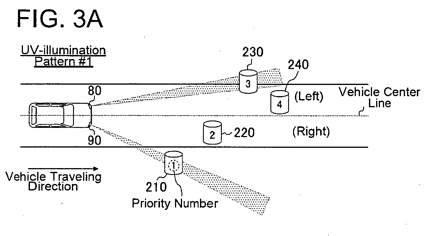
- the right-side UV light device 90 illuminates an object 210 to which the highest priority is assigned among objects 210 and 220 that exist on a lateral side (e.g. the right side) with respect to the vehicle center axis
- left-side UV light device 80 illuminates an object 230 to which the highest priority is assigned among objects 230 and 240 that exist in the opposite lateral side (e.g. the left side) with respect to the vehicle center axis.
- This pattern control is performed as follows.
- ECU 50 determines whether object 210 to which the highest priority was assigned in Step ST170 exists either on the right side or the left side with respect to the vehicle center axis. In the example of Fig. 3A , object 210 is determined to be located on the right side. Next, ECU 50 calculates or determines a light-distribution angle (particularly the axis of the light-beam and/or the spread thereof) to at least partly direct the UV light illuminated from a UV light device on the side according to the determination (in this example, the right-side UV light device 90) to object 210.
- a light-distribution angle particularly the axis of the light-beam and/or the spread thereof
- actuator 70 actuates the optical element (preferably rotates or pivots or displaces the adjustable reflector 82 and/or the optical lens) based on the light-distribution angle calculated or determined by ECU 50 to at least partly illuminate object 210 with the UV light from the UV light device 90.
- ECU 50 specifies object 230 to which the highest priority was assigned on this side.
- ECU 50 calculates or determines a light-distribution angle (particularly the axis of the light-beam and/or the spread thereof) to at least partly direct the UV light illuminated from the left-side UV light device 80 to object 230.
- actuator 60 actuates the optical element (preferably rotates or pivots or displaces the adjustable reflector 82 and/or the optical lens) based on the light-distribution angle calculated or determined by ECU 50 to at least partly illuminate object 230 with the UV light from UV light device 80.
- UV-illumination pattern #2 the highest-priority object 210 among the objects 210-230 that exist ahead of the vehicle is illuminated by the UV light devices 80 and 90 on both the left-and-right sides.
- This pattern control is performed as follows.
- ECU 50 determines whether object 210 to which the highest priority was assigned in Step ST170 exists either on the right side or the left side with respect to the vehicle center axis. In the example of Fig. 3B , ECU 50 determines that the object 210 exists on the right side. Next, ECU 50 calculates or determines a light-distribution angle (particularly the axis of the light-beam and/or the spread thereof) to at least partly direct the UV light illuminated from a UV light device on the side according to the determination (that is, the right-side UV light device 90 in the example of Fig. 3B ) to object 210.
- a light-distribution angle particularly the axis of the light-beam and/or the spread thereof
- actuator 70 actuates the optical element (preferably rotates or pivots or displaces the adjustable reflector 82 and/or the optical lens) based on the light-distribution angle calculated or determined by ECU 50 to at least partly illuminate object 210 with the UV light from UV light device 90.
- ECU 50 calculates or determines a light-distribution angle (particularly the axis of the light-beam and/or the spread thereof) to at least partly direct the UV light illuminated from the UV light device on the opposite side of the determination (that is, the left-side UV light device 80 in the example of Fig. 3B ) to object 210.
- actuator 60 actuates the optical element (preferably rotates or pivots or displaces the adjustable reflector 82 and/or the optical lens) based on the light-distribution angle calculated or determined by ECU 50 to at least partly illuminate object 210 with the UV light from UV light device 80.
- the highest-priority object 210 among the objects 210-230 that exist ahead of the vehicle preferably is illuminated by UV light device 90 on the same side as the object, and the second-highest-priority object 220 is illuminated by the UV light device 80 on the opposite side.
- This pattern control is performed as follows.
- ECU 50 determines whether object 210 to which the highest priority was assigned in Step ST170 exists either on the right side or the left side with respect to the vehicle center axis. In the example of Fig. 4A , ECU 50 determines that object 210 exists on the right side. Next, ECU 50 calculates or determines a light-distribution angle (particularly the axis of the light-beam and/or the spread thereof) to at least partly direct the UV light illuminated from a UV light device on the side according to the determination (that is, the right-side UV light device 90in the example of Fig. 4A ) to object 210.
- a light-distribution angle particularly the axis of the light-beam and/or the spread thereof
- actuator 70 actuates the optical device (preferably rotates or pivots or displaces the adjustable reflector 82 and/or the optical lens) based on the light-distribution angle calculated or determined by ECU 50 to at least partly illuminate object 210 with the UV light from the UV light device 90. Further, ECU 50 calculates or determines a light-distribution angle (particularly the axis of the light-beam and/or the spread thereof) to at least partly direct the UV light illuminated from the UV light device on the opposite side to the determination (that is, the left-side UV light device 80 in the example of Fig. 4A ) to object 220 to which the second highest priority was assigned in Step ST170.
- the optical device preferably rotates or pivots or displaces the adjustable reflector 82 and/or the optical lens
- the actuator 60 actuates the optical element (preferably rotates or pivots or displaces adjustable reflector 82 and/or the optical lens) based on the light-distribution angle calculated by ECU 50 to at least partly illuminate object 220 with the UV light from UV light device 80.
- the optical element preferably rotates or pivots or displaces adjustable reflector 82 and/or the optical lens
- UV-illumination pattern #4 the highest-priority object 210 among the objects 210-230 that exist ahead of the vehicle is illuminated by UV light device 90 on the same side as the object 210, while UV light device 80 on the opposite side illuminates the white line of the road shoulder.
- This pattern control is performed as follows.
- ECU 50 determines whether object 210 to which the highest priority was assigned in Step ST170 exists either on the right side or the left side with respect to the vehicle center axis. In the example of Fig. 4B , ECU 50 determines that object 210 exists on the right side. Next, ECU 50 calculates or determines a light-distribution angle (particularly the axis of the light-beam and/or the spread thereof) to at least partly direct the UV light illuminated from a UV light device on the side according to the determination (that is, the right-side UV light device 90 in the example of Fig. 4B ) to object 210.
- a light-distribution angle particularly the axis of the light-beam and/or the spread thereof
- actuator 70 actuates the optical element (preferably rotates or pivots or displaces adjustable reflector 82 and/or the optical lens) based on the light-distribution angle calculated or determined by ECU 50 to at least partly illuminate object 210 with the UV light from UV light device 90.
- the optical element preferably rotates or pivots or displaces adjustable reflector 82 and/or the optical lens
- ECU 50 calculates a light-distribution angle (particularly the axis of the light-beam and/or the spread thereof) to at least partly direct the UV light illuminated from a UV light device on the opposite side of the determination (that is, the left-side UV light device 80 in the example of Fig. 4B ) to the white line of the road shoulder and/or to the median line.
- a light-distribution angle (particularly the axis of the light-beam and/or the spread thereof) to at least partly direct the UV light illuminated from a UV light device on the opposite side of the determination (that is, the left-side UV light device 80 in the example of Fig. 4B ) to the white line of the road shoulder and/or to the median line.
- This process is performed similar to Step ST160.
- actuator 60 actuates the optical element (preferably rotates or pivots or displaces the adjustable reflector 82 and/or the optical lens) based on light-distribution angle calculated or determined by ECU 50 to at least partly
- ECU 50 preferably causes one or more actuators 60 and 70 to expand the illumination range (or to widen the illumination conus in lateral and/or vertical direction) of the UV light illuminated from UV light devices 80 and 90.
- actuators 60 and 70 each preferably controls the spatial relationship between light-source valve 81 and adjustable reflector 82 and/or the lens to expand the illumination range (i.e., illumination angle) of the UV light by diffusing the UV light flux illuminated from UV light devices 80 and 90.
- ECU 50 performs one of the following UV-illumination patterns #5 and #6.
- UV-illumination pattern #5 the highest-priority object 210 among objects 210, 230, 250, and 270 that exist on the right side with respect to the vehicle center axis is illuminated by the right-side UV light device 90, while the highest-priority object 220 among objects 220, 240, 260, and 280 that exist on the left side with respect to the vehicle center axis is illuminated by left-side UV light device 80.
- This pattern control is performed as follows.
- ECU 50 determines whether object 210 to which the highest priority was assigned in Step ST170 exists either on the right side or the left side with respect to the vehicle center axis. In the example of Fig. 5A , ECU 50 determines that object 210 exists on the right side. Next, ECU 50 calculates a light-distribution angle to direct the UV light illuminated from a UV light device on the side according to the determination (that is, the right-side UV light device 90 in the example of Fig. 5A ) to object 210. Then, actuator 70 rotates adjustable reflector 82 based on the light-distribution angle calculated by ECU 50 to illuminate object 210 with the UV light from UV light device 90.
- ECU 50 specifies object 220 to which the highest priority was assigned on the opposite side of the determination (that is, on the left side in the example of Fig. 5A ), and calculates a light-distribution angle to direct the UV light illuminated from left-side UV light device 80 to object 220. Then, actuator 60 rotates adjustable reflector 82 based on the light-distribution angle calculated by ECU 50 to illuminate object 220 with the UV light from UV light device 80.
- UV-illumination pattern #6 a center-of-gravity position 300 of objects 210-280 that exist ahead of the vehicle is illuminated by UV light devices 80 and 90 on both the left-and-right sides.
- This pattern control is performed as follows.
- ECU 50 calculates the center-of-gravity position 300 of objects 210-280 to be UV-illuminated.
- center-of-gravity position means a barycentric coordinate point of the object group in a coordinate system of a plane parallel to a traveling road surface indicated by an axis along the vehicle's longitudinal center line and an axis along the vehicle's transverse center line.
- ECU 50 calculates light-distribution angles to direct the UV lights illuminated from UV light devices 80 and 90 to center-of-gravity position 300. Then, the actuators 60 and 70 rotate adjustable reflectors 82 based on the light-distribution angles calculated by ECU 50 to illuminate center-of-gravity position 300 with the UV light from UV light devices 80 and 90.
- UV light(s) may be varied to be one or three or more depending on the circumstances.
- object detection and/or the priority determination may be performed in any other suitable manner.
- the vehicle operation support system for the vehicle may be capable of changing or modifying or controlling the direction and/or the spread of the UV light illumination as needed.
- a driver's visibility over an obstacle in proximity to the vehicle may be improved.
- the device may change the illumination direction (particularly corresponding to the center or median line of the light conus being irradiated), illumination range or spread (particularly the angular distribution or width with respect to the illumination direction), and/or illumination intensity of the UV light from UV light devices 80 and/or 90 in accordance with the object detection.
- the driver's visibility may be improved compared with a case where the direction of the UV light illumination is preset and fixed in advance.
- UV-headlights 80 and 90 may be provided in or near a front portion of the vehicle particularly on the left and right sides, respectively, and actuators 60 and 70 may be provided to change the illumination directions and/or spreads of UV-headlights 80 and 90, respectively.
- illumination patterns #1 through #6 the illumination directions of the UV-headlights 80 and 90 on the left and right sides may be separately controlled.
- the illumination patterns #1 through #6 solely show examples of the pattern controls according to the invention. Therefore, other various illumination patterns may also be realized.
- the invention may be useful for a vehicle operation support system that is applied to improve the driver's visibility, especially, the driver's night visibility of pedestrians and obstacles that may exist forward of the vehicle.
- the vehicle may be equipped with at least one UV light which irradiates the ambient environment with UV radiation.
- the direction, angular width in lateral and/or vertical direction and/or the intensity of UV radiation may be changed in response to vehicle and environment variables.
Landscapes
- Engineering & Computer Science (AREA)
- Mechanical Engineering (AREA)
- Lighting Device Outwards From Vehicle And Optical Signal (AREA)
- Traffic Control Systems (AREA)
Abstract
Description
- The present invention relates to a vehicle operation support method or system. More particularly, the invention relates to a method or system for improving a driver's visibility over obstacles, such as a pedestrian in an ambient environment of the vehicle.
- Vehicle manufacturers have addressed the development and evolution of various methods and systems, which improve the safety performance of vehicles. One attempt to improve a driver's visibility is a method for providing headlights that irradiate the front area of the vehicle with ultra-violet (UV) radiation to improve visibility of a pedestrian in a front area of the vehicle during night driving. One example of this method is described by Japanese Unexamined Patent Application Publication No.
2000-203335 - Another example of this method is described by Japanese Unexamined Patent Application Publication No.
2000-027128A - In one approach, a method of improving the a driver's visibility of the environment outside a vehicle equipped with at least one UV light which irradiates the ambient environment of said vehicle with UV radiation is provided. This method comprises irradiating the ambient environment of the vehicle with UV radiation from the UV light and changing a direction of irradiation of the UV radiation.
- In another approach, a method of improving a driver's visibility of the environment outside a vehicle equipped with at least one UV light which irradiates the ambient environment of the vehicle with UV radiation, while a sensor detects an object in the ambient environment of the vehicle is provided. This method comprises changing the direction of UV irradiation according to a detection result of the sensor.
- In another approach, a method of improving a driver's visibility of the environment outside a vehicle equipped with at least one UV light which irradiates the ambient environment of the vehicle with UV radiation and a sensor that detects an object in the ambient environment of the vehicle is provided. This method comprises changing an intensity of the UV radiation reaching the object detected by the sensor according to a determined type of the object. As one of the examples, when an object is a pedestrian, the intensity is made lower.
- In this way, a driver's visibility of an obstacle existing in the ambient environment of the vehicle may be improved, while the negative influence of UV radiation on the pedestrian may be reduced.
- It is an object of the invention to improve the obstacle detection.
- This object is solved according to the invention by the features of the independent claims. Preferred embodiments of the invention are subject of the dependent claims.
- According to one aspect of the invention, there is provided a method of improving a driver's visibility of the environment outside a vehicle equipped with at least one UV light which irradiates the ambient environment of said vehicle with UV radiation, the method comprising:
- irradiating the ambient environment of said vehicle with UV radiation from said UV light; and
- changing or modifying or controlling a direction and/or angular distribution of irradiation of said UV radiation.
- According to one particular example, said vehicle is equipped with at least one sensor which can detect at least one object in the ambient environment of said vehicle; and said changing the direction and/or angular distribution of irradiation of UV radiation includes changing the direction and/or angular distribution according to a detection result of said sensor.
- According to one particular example, the method further comprises determining a collision possibility of the object with said vehicle detected by said sensor; wherein said changing the direction and/or angular distribution of irradiation of said UV radiation includes directing the direction and/or angular distribution to said object upon it being determined that the object has a specified (predetermined or predeterminable) degree of the collision possibility with the vehicle.
- According to one particular example, the method further comprises changing an intensity of said UV radiation reaching said object detected by said sensor according to a determined type of said object.
- According to one particular example, said intensity of said UV radiation reaching said object is set to a first intensity when said object is not determined to be a pedestrian and wherein said intensity is set to a second intensity that is lower than said first intensity when said object is determined to be a pedestrian.
- According to one particular example, changing the direction and/or angular distribution of irradiation of said UV radiation irradiated from said UV light occurs when a plurality of objects are detected by said sensor.
- According to one particular example, the method further comprises setting an order of priority for each object according to a degree of risk of collision of each object with said vehicle; wherein said changing the direction and/or angular distribution of irradiation of said UV radiation includes changing the direction and/or angular distribution according to said order of priority of each object.
- According to one particular example, selecting at least one object from said plurality of objects on the basis of said order of priority; wherein said changing the direction and/or angular distribution of irradiation of said UV radiation includes directing said UV radiation to selected objects.
- According to one particular example, the method further comprises calculating or determining the center position of said plurality of objects along a vehicle width direction and/or a vehicle longitudinal direction; wherein said changing the direction and/or angular distribution of irradiation of said UV radiation includes directing said UV radiation to said center position.
- According to one particular example, the changing the angular distribution of the UV radiation comprises expanding the irradiation range of said UV radiation when a plurality of objects are detected by said sensor.
- According to one particular example, said vehicle is equipped at least with a right UV light on a right-hand side of a vehicle body and a left UV light on a left-hand side of said vehicle body, the method further comprising: determining whether said object detected is on a right-hand side of said vehicle or on a left-hand side of said vehicle; wherein irradiating said object on the right-hand side is accomplished with UV radiation from said right UV light and irradiating said object on the left-hand side is accomplished with UV radiation from said left UV light.
- According to a further aspect of the invention, there is provided a computer program product, in particular embodied on a computer-redable storage medium, as a signal or data stream, comprising computer readable instructions which, when loaded and executed on a suitable system perform the steps of a method according to the above aspect or examples.
- According to a further aspect of the invention, there is provided a vehicle operation support system, comprising:
- at least one UV light irradiating an ambient environment of a vehicle;
- at least one actuator capable of changing or modifying or controlling a direction and/or angular distribution of UV irradiation from the UV light; and
- a controller configured to control said at least one actuator.
- According to one particular example, the system further comprises: at least one sensor which detects an object in the ambient environment of said vehicle and that is capable of communicating with said controller; wherein said controller is configured to control said actuator according to an input from said sensor.
- According to one particular example, said controller is configured to determine a collision possibility of the object detected by said sensor with said vehicle, and wherein the controller controls said actuator such that said direction and/or angular distribution of irradiation is directed to said object upon determining that the object has a specified (predetermined or predeterminable) degree of collision possibility.
- According to one particular example, the system further comprises an intensity changing mechanism for changing an intensity of said UV radiation reaching said object detected by said sensor; wherein said controller is configured to determine a type of said object and is configured to control said intensity changing mechanism according to the determined type of object.
- According to one particular example, said controller is configured to determine whether said object detected by said sensor is a pedestrian or not, and to control said intensity changing mechanism such that an intensity of said UV radiation reaching said object is set to a first intensity when said object is not determined to be a pedestrian and said intensity is set to a second intensity that is lower than said first intensity when said object is determined to be a pedestrian.
- According to one particular example, said controller is configured to change said actuator control when a plurality of objects are detected by said sensor.
- According to one particular example, said controller is configured to set an order of priority for each object according to a degree of risk of collision with the vehicle when a plurality of objects are detected by said sensor, and to change the direction and/or angular distribution of irradiation of said UV radiation according to said order of priority for each object.
- According to one particular example, said controller is configured to select at least one object from said plurality of objects on the basis of said order of priority and to direct said UV radiation to selected objects.
- According to one particular example, said controller is configured to calculate the center position of said plurality of objects along a vehicle width direction and/or a vehicle longitudinal direction and to direct said UV radiation to said center position.
- According to one particular example, said controller is configured to expand the irradiation range of said UV radiation when a plurality of objects are detected by said sensor.
- According to one particular example, a right UV light which irradiates a vehicle right side front area with UV radiation is provided on a right-hand side of a vehicle front body, a left UV light which irradiates a vehicle left side front area with UV radiation is provided on a left-hand side of said vehicle front body, the system further comprising: a first actuator capable of changing the direction and/or angular distribution of said UV radiation from said right UV light; and a second actuator capable of changing the direction and/or angular distribution of said UV radiation from said left UV light.
- According to one particular example, said controller is configured to determine whether said object is on a right-hand side of said vehicle or a on a left-hand side of said vehicle, to control said first actuator such that said first UV light irradiates said object when said object is on the right-hand side of said vehicle and to control said second actuator such that said second UV light irradiates said object when said object is on the left-hand side of said vehicle.
- These and other objects, features and advantages of the present invention will become more apparent upon reading of the following detailed description of preferred embodiments and accompanying drawings. It should be understood that even though embodiments are separately described, single features thereof may be combined to additional embodiments.
-
Fig. 1A is a block diagram showing a system configuration of a vehicle operation support system for a vehicle according to an embodiment of the invention, andFigs. 1B and 1C are schematic views showing implementations of the UV light device on the vehicle. -
Fig. 2 is a flowchart showing an operational procedure of the vehicle operation support system shown inFig. 1A . -
Figs. 3A and 3B ,4A and 4B , and5A and 5B are schematic views showing illumination patterns by the vehicle operation support system in accordance with the operational procedure shown inFig. 2 . - Hereinafter, several embodiments of the present invention will be explained in detail with reference to the appended drawings. In the drawings, like reference numerals indicate like portions and, thus, explanation thereof will not be repeated.
-
Fig. 1A shows a system configuration of a vehicle operation support system for a vehicle according to one preferred embodiment of the invention. InFig. 1A , this vehicle operation support system includes at least one vehicle-speed sensor 10, at least oneradar 20, at least onecamera 30, at least one yaw-rate sensor 40, an electronic control unit (ECU) 50, one ormore actuators UV light devices - The vehicle-
speed sensor 10 detects or determines a traveling speed of the vehicle. Referring toFigs. 1B and 1C , theradar 20 is disposed particularly in proximity to or on a radiator grill on or near the vehicle's front face, and thecamera 30 is disposed particularly at or near a front end of an inner roof inside the vehicle cabin or at or near a front end of outer roof. Theradar 20 andcamera 30 are used to detect or determine a distance to an object substantially in front of the vehicle, that is, in a front area of the vehicle, a shape of the object and/or a direction of the object with respect to the vehicle's heading or driving direction, etc. The yaw-rate sensor 40 detects or determines a yaw rate of the vehicle to estimate the vehicle's heading or vehicle direction along with the vehicle-speed sensor 10.ECU 50 typically is a computer that performs various calculations for the drive-assist functions, as described below. - The UV light device(s) 80 and/or 90 is/are disposed particularly on or near the front face of the vehicle on the lateral (left and/or right) sides, respectively, to illuminate UV light (particularly a frequency in the range of 400 nm to 200 nm) in a specified (predetermined or predeterminable) direction, preferably substantially ahead of the vehicle. Preferably, 315 nm or longer wavelengths (particularly a frequency in the range of 400 nm to 315 nm) may be used for the UV light illuminated from UV
light devices light devices - Actuator(s) 60 and/or 70 change(s) the direction(s) of the UV light or light conus from the
UV light devices 80 and/or 90. Further, theactuators UV light devices actuator 60/70 may vary or control the lateral and/or vertical light emission or expansion of theUV light device 80/90. Further,actuators light devices - The implementation of UV
light devices - One example of the "separate type" is shown in
Fig. 1B , and this type is configured such that UVlight devices headlights 100, which illuminate ahead of the vehicle with visible light. In this embodiment, configurations of theheadlights 100 are know to those skilled in the art and, thus, explanation thereof will be omitted. - The UV light is emitted from light-source valve or bulb or
device 81 of UVlight device 80, and the UV light is then reflected substantially ahead of the vehicle by at least one optical element, preferably comprising at least oneadjustable reflector 82 and/or at least one lens device.Actuator 60 actuates the optical element, preferably rotates or pivots or displacesadjustable reflector 82 and/or the lens device in the vertical and/or horizontal directions, to change the direction of UV light illumination. Further,actuator 60 can change or control a spatial relationship between light-source valve 81 and the optical element (particularly theadjustable reflector 82 and/or the lens device) to diffuse/centralize the light flux of the UV light so as to expend or narrow the illumination range of the UV light (i.e., the illumination angle) in lateral and/or vertical direction. - In this embodiment,
UV light device 90 has a similar structure and operation to UVlight device 80 and, thus, explanation thereof will be omitted. Further,UV light devices intensity changing mechanism 85 for changing intensities of the UV light by adjusting current applied to the light-source valves of UVlight devices - Turning to
Fig. 1C , for the "built-into-headlight type,"UV light devices headlights 100 for illuminating in front of the vehicle with visible light. - For example, in UV
light device 80, light-source valve or bulb ordevice 81 emits UV light as well as visible light. In other words, the light-source valve or bulb ordevice 81 emits light in a frequency range comprising not only Uvlight, but also other components such as visible light. However, preferably only UV light (preferably UV-A light) penetrates or passes at least onefilter 83 to illuminate substantially ahead of the vehicle. Further, similar to the "separate type" described above, the illumination direction and/or illumination range or spread (angular width) of the UV light are controlled by (preferably each of) the actuator(s) 60 and/or 70. In this embodiment, thefilter 83 preferably does not function or is inactive when illuminating with visible light ahead of the vehicle (i.e., when the low and/or high beam is turned on). Further, the control of the illumination direction(s) and/or the illumination range(s) or spread(s) by actuator(s) 60 and/or 70 preferably is not performed when illuminating with visible light in front of the vehicle (i.e., when the low and/or high beam is turned on). This is because an operator of an oncoming vehicle may be dazzled by the visible light. Further,UV light devices - In this embodiment, a low-beam unit of
headlight 100 is configured so that an illumination axis thereof is adjustable in any direction by the actuator preferably in accordance with a steering angle of the vehicle and/or a speed of the vehicle (referred to as an "Adaptive Front Lighting System"). - Next, referring to a flowchart of
Fig. 2 , an operation of the vehicle operation support system for the vehicle configured as described above will be explained. - First, in ST100,
ECU 50 determines whether a traveling speed detected by vehicle-speed sensor 10 is zero or below a specified (predetermined or predeterminable) threshold. When the traveling speed is determined to be zero or below the specified (predetermined or predeterminable) threshold, then, in ST110,ECU 50 instructs a termination of the UV light illumination to actuator(s) 60 and/or 70 and UV light device(s) 80 and/or 90. - On the other hand, when the traveling speed is determined to be non-zero or not below the specified (predetermined or predeterminable) threshold, then, in ST120,
ECU 50 performs an "object-detection process." The object-detection process may be performed by cooperation ofradar 20,camera 30, yaw-rate sensor 40, andECU 50, as follows. - First,
ECU 50 estimates the vehicle's heading or traveling direction by a method based on the detected information from vehicle-speed sensor 10 and/or yaw-rate sensor 40. Theradar 20 and/or thecamera 30 detect at least one object that exists substantially ahead of the estimated heading or traveling direction of the vehicle. Next,ECU 50 calculates or determines a distance to the detected object, a shape of the object, a moving direction of the object and/or a moving speed of the object, etc. - In this embodiment, the estimation of the vehicle's heading or traveling direction may be performed using a steering angle sensor and/or a steering angular velocity sensor, etc.
- Next, in ST130,
ECU 50 determines an existence of collision possibility of the vehicle to each of the detected objects. The determination of the existence of collision possibility may be performed by a method based on information including the moving speed and/or trace of the object, the traveling speed and/or trace of the vehicle, etc. - Next, in ST140,
ECU 50 sets the object determined to be "collision possibility exists" in Step ST130 to an object to be UV-illuminated. On the other hand, when there is no object to be UV-illuminated in ST150,ECU 50 then proceeds to Step ST160, or otherwise,ECU 50 proceeds to Step ST170. - In ST160,
ECU 50 performs a control in which the UV light illuminated from UVlight devices -
ECU 50 may recognize the white line of the road based on the information fromcamera 30 or yaw-rate sensor 40, and may calculate or determine the illumination directions (i.e., light-distribution angle(s)) of UVlight devices - Then,
ECU 50 causes actuators 60 and 70 to actuate the optical element (particularly to rotate or pivot or displace theadjustable reflectors 82 and/or the lens device) based on the calculated or determined light-distribution angles so that the UV light from UVlight devices - In ST170,
ECU 50 assigns priorities to the objects to be UV-illuminated. The priorities may be determined based on a degree of danger to the vehicle which may be based on a distance of the object to the vehicle and/or a degree of the collision possibility, or the like. - For example, the degree of collision possibility may be represented by an expected time to collision that can be calculated or determined based on a object's moving vector and/or a vehicle's traveling vector (for example, a width of the traveling vector may be set to the vehicle width).
- Further, the priorities may be determined based on whether the object to be UV-illuminated is a pedestrian. For example, if the objects are determined to be a pedestrian, a road sign, and a road marking, the pedestrian is set to the highest priority.
- Next, in ST180,
ECU 50 determines whether a pedestrian is included among the objects to be UV-illuminated. This determination may be performed by checking whether a ratio of the detected object's width and/or height is within a predetermined or predeterminable range. - When a pedestrian is determined to be included, then, in ST190,
ECU 50 causes actuators 60 and 70 to preferably set the illumination output levels of UVlight devices ECU 50 also causesactuators light devices - On the other hand, when a pedestrian is determined not to be included among the objects to be UV illuminated, then, in ST200,
ECU 50 preferably causesactuators light devices ECU 50 also causesactuators UV light devices - Next, in ST210,
ECU 50 determines whether a count of the objects to be UV-illuminated is more than N (in this embodiment, N= 5). This determination may be performed in order to form a suitable UV-illumination pattern for a case where the count of the objects is relatively large (more than N), or a case where the count is less than N. - When the count of the objects to be UV-illuminated is determined to be less than N (less than or equal four in this example), then, in ST220,
ECU 50 may perform one of the following UV-illumination patterns # 1 through #4. - As shown in
Fig. 3A , in UV-illumination pattern # 1, the right-sideUV light device 90 illuminates anobject 210 to which the highest priority is assigned amongobjects UV light device 80 illuminates anobject 230 to which the highest priority is assigned amongobjects -
ECU 50 determines whetherobject 210 to which the highest priority was assigned in Step ST170 exists either on the right side or the left side with respect to the vehicle center axis. In the example ofFig. 3A , object 210 is determined to be located on the right side. Next,ECU 50 calculates or determines a light-distribution angle (particularly the axis of the light-beam and/or the spread thereof) to at least partly direct the UV light illuminated from a UV light device on the side according to the determination (in this example, the right-side UV light device 90) to object 210. Then, actuator 70 actuates the optical element (preferably rotates or pivots or displaces theadjustable reflector 82 and/or the optical lens) based on the light-distribution angle calculated or determined byECU 50 to at least partly illuminateobject 210 with the UV light from theUV light device 90. - On the other hand, for the opposite side of the determination (i.e., left side in the example of
Fig. 3A ),ECU 50 specifiesobject 230 to which the highest priority was assigned on this side. Next,ECU 50 calculates or determines a light-distribution angle (particularly the axis of the light-beam and/or the spread thereof) to at least partly direct the UV light illuminated from the left-sideUV light device 80 to object 230. Then, actuator 60 actuates the optical element (preferably rotates or pivots or displaces theadjustable reflector 82 and/or the optical lens) based on the light-distribution angle calculated or determined byECU 50 to at least partly illuminateobject 230 with the UV light from UVlight device 80. - As shown in
Fig. 3B , in UV-illumination pattern # 2, the highest-priority object 210 among the objects 210-230 that exist ahead of the vehicle is illuminated by theUV light devices - First,
ECU 50 determines whetherobject 210 to which the highest priority was assigned in Step ST170 exists either on the right side or the left side with respect to the vehicle center axis. In the example ofFig. 3B ,ECU 50 determines that theobject 210 exists on the right side. Next,ECU 50 calculates or determines a light-distribution angle (particularly the axis of the light-beam and/or the spread thereof) to at least partly direct the UV light illuminated from a UV light device on the side according to the determination (that is, the right-sideUV light device 90 in the example ofFig. 3B ) to object 210. Then, actuator 70 actuates the optical element (preferably rotates or pivots or displaces theadjustable reflector 82 and/or the optical lens) based on the light-distribution angle calculated or determined byECU 50 to at least partly illuminateobject 210 with the UV light from UVlight device 90. On the other hand, for the opposite side,ECU 50 calculates or determines a light-distribution angle (particularly the axis of the light-beam and/or the spread thereof) to at least partly direct the UV light illuminated from the UV light device on the opposite side of the determination (that is, the left-sideUV light device 80 in the example ofFig. 3B ) to object 210. Then, actuator 60 actuates the optical element (preferably rotates or pivots or displaces theadjustable reflector 82 and/or the optical lens) based on the light-distribution angle calculated or determined byECU 50 to at least partly illuminateobject 210 with the UV light from UVlight device 80. - As shown in
Fig. 4A , in UV-illumination pattern # 3, the highest-priority object 210 among the objects 210-230 that exist ahead of the vehicle preferably is illuminated byUV light device 90 on the same side as the object, and the second-highest-priority object 220 is illuminated by theUV light device 80 on the opposite side. This pattern control is performed as follows. - First,
ECU 50 determines whetherobject 210 to which the highest priority was assigned in Step ST170 exists either on the right side or the left side with respect to the vehicle center axis. In the example ofFig. 4A ,ECU 50 determines thatobject 210 exists on the right side. Next,ECU 50 calculates or determines a light-distribution angle (particularly the axis of the light-beam and/or the spread thereof) to at least partly direct the UV light illuminated from a UV light device on the side according to the determination (that is, the right-side UV light device 90in the example ofFig. 4A ) to object 210. Then, actuator 70 actuates the optical device (preferably rotates or pivots or displaces theadjustable reflector 82 and/or the optical lens) based on the light-distribution angle calculated or determined byECU 50 to at least partly illuminateobject 210 with the UV light from theUV light device 90. Further,ECU 50 calculates or determines a light-distribution angle (particularly the axis of the light-beam and/or the spread thereof) to at least partly direct the UV light illuminated from the UV light device on the opposite side to the determination (that is, the left-sideUV light device 80 in the example ofFig. 4A ) to object 220 to which the second highest priority was assigned in Step ST170. Then, theactuator 60 actuates the optical element (preferably rotates or pivots or displacesadjustable reflector 82 and/or the optical lens) based on the light-distribution angle calculated byECU 50 to at least partly illuminateobject 220 with the UV light from UVlight device 80. - As shown in
Fig. 4B , in UV-illumination pattern # 4, the highest-priority object 210 among the objects 210-230 that exist ahead of the vehicle is illuminated byUV light device 90 on the same side as theobject 210, while UVlight device 80 on the opposite side illuminates the white line of the road shoulder. This pattern control is performed as follows. - First,
ECU 50 determines whetherobject 210 to which the highest priority was assigned in Step ST170 exists either on the right side or the left side with respect to the vehicle center axis. In the example ofFig. 4B ,ECU 50 determines thatobject 210 exists on the right side. Next,ECU 50 calculates or determines a light-distribution angle (particularly the axis of the light-beam and/or the spread thereof) to at least partly direct the UV light illuminated from a UV light device on the side according to the determination (that is, the right-sideUV light device 90 in the example ofFig. 4B ) to object 210. Then, actuator 70 actuates the optical element (preferably rotates or pivots or displacesadjustable reflector 82 and/or the optical lens) based on the light-distribution angle calculated or determined byECU 50 to at least partly illuminateobject 210 with the UV light from UVlight device 90. - Further,
ECU 50 calculates a light-distribution angle (particularly the axis of the light-beam and/or the spread thereof) to at least partly direct the UV light illuminated from a UV light device on the opposite side of the determination (that is, the left-sideUV light device 80 in the example ofFig. 4B ) to the white line of the road shoulder and/or to the median line. This process is performed similar to Step ST160. Then, actuator 60 actuates the optical element (preferably rotates or pivots or displaces theadjustable reflector 82 and/or the optical lens) based on light-distribution angle calculated or determined byECU 50 to at least partly illuminate the white line of the road (shoulder and/or median line) with the UV light from UVlight device 80. - When the count of the objects to be UV-illuminated is determined to be more than N (in this example, five) in Step ST210, then, in ST230,
ECU 50 preferably causes one ormore actuators light devices source valve 81 andadjustable reflector 82 and/or the lens to expand the illumination range (i.e., illumination angle) of the UV light by diffusing the UV light flux illuminated from UVlight devices - Then, in ST240,
ECU 50 performs one of the following UV-illumination patterns # 5 and #6. - As shown in
Fig. 5A , in UV-illumination pattern # 5, the highest-priority object 210 amongobjects UV light device 90, while the highest-priority object 220 amongobjects UV light device 80. This pattern control is performed as follows. - First,
ECU 50 determines whetherobject 210 to which the highest priority was assigned in Step ST170 exists either on the right side or the left side with respect to the vehicle center axis. In the example ofFig. 5A ,ECU 50 determines thatobject 210 exists on the right side. Next,ECU 50 calculates a light-distribution angle to direct the UV light illuminated from a UV light device on the side according to the determination (that is, the right-sideUV light device 90 in the example ofFig. 5A ) to object 210. Then, actuator 70 rotatesadjustable reflector 82 based on the light-distribution angle calculated byECU 50 to illuminateobject 210 with the UV light from UVlight device 90. Further,ECU 50 specifiesobject 220 to which the highest priority was assigned on the opposite side of the determination (that is, on the left side in the example ofFig. 5A ), and calculates a light-distribution angle to direct the UV light illuminated from left-sideUV light device 80 to object 220. Then, actuator 60 rotatesadjustable reflector 82 based on the light-distribution angle calculated byECU 50 to illuminateobject 220 with the UV light from UVlight device 80. - As shown in
Fig. 5B , in UV-illumination pattern # 6, a center-of-gravity position 300 of objects 210-280 that exist ahead of the vehicle is illuminated byUV light devices - First,
ECU 50 calculates the center-of-gravity position 300 of objects 210-280 to be UV-illuminated. As used herein, the term "center-of-gravity position" means a barycentric coordinate point of the object group in a coordinate system of a plane parallel to a traveling road surface indicated by an axis along the vehicle's longitudinal center line and an axis along the vehicle's transverse center line. - Next,
ECU 50 calculates light-distribution angles to direct the UV lights illuminated from UVlight devices gravity position 300. Then, theactuators adjustable reflectors 82 based on the light-distribution angles calculated byECU 50 to illuminate center-of-gravity position 300 with the UV light from UVlight devices - It should be understood that the number and/or location of the UV light(s) may be varied to be one or three or more depending on the circumstances. Moreover, the object detection and/or the priority determination may be performed in any other suitable manner.
- As described above, the vehicle operation support system for the vehicle according to the embodiments may be capable of changing or modifying or controlling the direction and/or the spread of the UV light illumination as needed. In this case, a driver's visibility over an obstacle in proximity to the vehicle may be improved. More specifically, the device may change the illumination direction (particularly corresponding to the center or median line of the light conus being irradiated), illumination range or spread (particularly the angular distribution or width with respect to the illumination direction), and/or illumination intensity of the UV light from UV
light devices 80 and/or 90 in accordance with the object detection. Thus, the driver's visibility may be improved compared with a case where the direction of the UV light illumination is preset and fixed in advance. - Further, UV-
headlights actuators headlights illumination patterns # 1 through #6, the illumination directions of the UV-headlights illumination patterns # 1 through #6 solely show examples of the pattern controls according to the invention. Therefore, other various illumination patterns may also be realized. - The invention may be useful for a vehicle operation support system that is applied to improve the driver's visibility, especially, the driver's night visibility of pedestrians and obstacles that may exist forward of the vehicle. Particularly, the vehicle may be equipped with at least one UV light which irradiates the ambient environment with UV radiation. In some examples, the direction, angular width in lateral and/or vertical direction and/or the intensity of UV radiation may be changed in response to vehicle and environment variables.
Claims (23)
- A method of improving a driver's visibility of the environment outside a vehicle equipped with at least one UV light (80, 90) which irradiates the ambient environment of said vehicle with UV radiation, the method comprising:irradiating the ambient environment of said vehicle with UV radiation from said UV light (80, 90); andchanging a direction and/or angular distribution of irradiation of said UV radiation.
- The method as described in claim 1 wherein said vehicle is equipped with at least one sensor (20; 30) which can detect at least one object (210, 220, 230, 240, 250, 260) in the ambient environment of said vehicle; and
wherein said changing the direction and/or angular distribution of irradiation of UV radiation includes changing the direction and/or angular distribution according to a detection result of said sensor (20; 30). - The method as described in claim 2, further comprising determining a collision possibility of the object with said vehicle detected by said sensor (20, 30);
wherein said changing the direction and/or angular distribution of irradiation of said UV radiation includes directing the direction and/or angular distribution to said object (210; 220, 230, 240, 250, 260) upon it being determined that the object (210, 220, 230, 240, 250, 260) has a specified degree of the collision possibility with the vehicle. - The method as described in any one of claims 2 or 3, further comprising changing an intensity of said UV radiation reaching said object (210, 220, 230, 240, 250, 260) detected by said sensor (20, 30) according to a determined type of said object (210, 220, 230, 240, 250, 260).
- The method as described in claim 4, wherein said intensity of said UV radiation reaching said object (210, 220, 230, 240, 250, 260) is set to a first intensity when said object (210, 220, 230, 240, 250, 260) is not determined to be a pedestrian and wherein said intensity is set to a second intensity that is lower than said first intensity when said object (210, 220, 230, 240, 250, 260) is determined to be a pedestrian.
- The method as described in any one of claims 2 through 5, wherein changing the direction and/or angular distribution of irradiation of said UV radiation irradiated from said UV light occurs when a plurality of objects (210, 220, 230, 240, 250, 260) are detected by said sensor (20; 30).
- The method as described in claim 6, further comprising setting an order of priority for each object according to a degree of risk of collision of each object (210, 220, 230, 240, 250, 260) with said vehicle;
wherein said changing the direction and/or angular distribution of irradiation of said UV radiation includes changing the direction and/or angular distribution according to said order of priority of each object (210, 220, 230, 240, 250, 260). - The method as described in claim 7, wherein selecting at least one object (210, 230) from said plurality of objects (210, 220, 230, 240, 250, 260) on the basis of said order of priority; and
wherein said changing the direction and/or angular distribution of irradiation of said UV radiation includes directing said UV radiation to selected objects (210, 230). - The method as described in claim 6, further comprising calculating the center position (300) of said plurality of objects (210, 220, 230, 240, 250, 260) along a vehicle width direction and/or a vehicle longitudinal direction;
wherein said changing the direction and/or angular distribution of irradiation of said UV radiation includes directing said UV radiation to said center position (300). - The method as described in any one of claims 2 through 9, wherein the changing the angular distribution of the UV radiation comprises expanding the irradiation range of said UV radiation when a plurality of objects (210, 220, 230, 240, 250, 260) are detected by said sensor (20, 30).
- The method as described in any one of the preceding claims, wherein said vehicle is equipped at least with a right UV light (90) on a right-hand side of a vehicle body and a left UV light (80) on a left-hand side of said vehicle body, the method further comprising:determining whether said object detected is on a right-hand side of said vehicle or on a left-hand side of said vehicle;wherein irradiating said object (210) on the right-hand side is accomplished with UV radiation from said right UV light (90) and irradiating said object (230) on the left-hand side is accomplished with UV radiation from said left UV light (80).
- A vehicle operation support system, comprising:at least one UV light (80, 90) irradiating an ambient environment of a vehicle;at least one actuator (60, 70) capable of changing a direction and/or angular distribution of UV irradiation from the UV light (80, 90); anda controller (50) configured to control said at least one actuator.
- The system as described in claim 12, further comprising:at least one sensor (20, 30) which detects an object (210, 220, 230, 240, 250, 260) in the ambient environment of said vehicle and that is capable of communicating with said controller (50);wherein said controller (50) is configured to control said actuator (60, 70) according to an input from said sensor (20, 30).
- The system as described in claim 13, wherein said controller (50) is configured to determine a collision possibility of the object (210, 220, 230, 240, 250, 260) detected by said sensor (20, 30) with said vehicle, and wherein the controller (50) controls said actuator (60, 70) such that said direction and/or angular distribution of irradiation is directed to said object (210, 220, 230, 240, 250, 260) upon determining that the object (210, 220, 230, 240, 250, 260) has a specified degree of collision possibility.
- The system as described in claim 13 or 14, further comprising:an intensity changing mechanism (85) for changing an intensity of said UV radiation reaching said object (210, 220, 230, 240, 250, 260) detected by said sensor (20, 30); wherein said controller (50) is configured to determine a type of said object (210, 220, 230, 240, 250, 260) and is configured to control said intensity changing mechanism (85) according to the determined type of object (210, 220, 230, 240, 250, 260).
- The system as described in claim 15, wherein said controller is configured to determine whether said object detected by said sensor (20, 30) is a pedestrian or not, and to control said intensity changing mechanism (85) such that an intensity of said UV radiation reaching said object (210, 220, 230, 240, 250, 260) is set to a first intensity when said object (210, 220, 230, 240, 250, 260) is not determined to be a pedestrian and said intensity is set to a second intensity that is lower than said first intensity when said object (210, 220, 230, 240, 250, 260) is determined to be a pedestrian.
- The system as described in any one of claims 13 through 16, wherein said controller is configured to change said actuator control when a plurality of objects (210, 220, 230, 240, 250, 260) are detected by said sensor (20, 30).
- The system as described in claim 17, wherein said controller (50) is configured to set an order of priority for each object (210, 220, 230, 240, 250, 260) according to a degree of risk of collision with the vehicle when a plurality of objects (210, 220, 230, 240, 250, 260) are detected by said sensor (20, 30), and to change the direction and/or angular distribution of irradiation of said UV radiation according to said order of priority for each object (210, 220, 230, 240, 250, 260).
- The system as described in claim 18, wherein said controller (50) is configured to select at least one object (210, 230) from said plurality of objects (210, 220, 230, 240, 250, 260) on the basis of said order of priority and to direct said UV radiation to selected objects (210, 230).
- The system as described in claim 17, 18 or 19, wherein said controller (50) is configured to calculate the center position (300) of said plurality of objects (210, 220, 230, 240, 250, 260) along a vehicle width direction and/or a vehicle longitudinal direction and to direct said UV radiation to said center position (300).
- The system as described in claim 17 or 20, wherein said controller (50) is configured to expand the irradiation range of said UV radiation when a plurality of objects (210, 220, 230, 240, 250, 260) are detected by said sensor (20, 30).
- The system as described in claims 12 through 21, wherein a right UV light (90) which irradiates a vehicle right side front area with UV radiation is provided on a right-hand side of a vehicle front body, a left UV light (80) which irradiates a vehicle left side front area with UV radiation is provided on a left-hand side of said vehicle front body, the system further comprising:a first actuator (70) capable of changing the direction and/or angular distribution of said UV radiation from said right UV light (90); anda second actuator (60) capable of changing the direction and/or angular distribution of said UV radiation from said left UV light (80).
- The system as described in claim 22 wherein said controller (50) is configured to determine whether said object (210, 220, 230, 240, 250, 260) is on a right-hand side of said vehicle or a on a left-hand side of said vehicle, to control said first actuator (70) such that said first UV light (90) irradiates said object (210) when said object(210) is on the right-hand side of said vehicle and to control said second actuator (60) such that said second UV light (80) irradiates said object (230) when said object (230) is on the left-hand side of said vehicle.
Applications Claiming Priority (1)
| Application Number | Priority Date | Filing Date | Title |
|---|---|---|---|
| JP2007067045A JP2008226140A (en) | 2007-03-15 | 2007-03-15 | Vehicle driving support device |
Publications (2)
| Publication Number | Publication Date |
|---|---|
| EP1970249A2 true EP1970249A2 (en) | 2008-09-17 |
| EP1970249A3 EP1970249A3 (en) | 2009-07-15 |
Family
ID=39523233
Family Applications (1)
| Application Number | Title | Priority Date | Filing Date |
|---|---|---|---|
| EP08004302A Withdrawn EP1970249A3 (en) | 2007-03-15 | 2008-03-07 | Vehicle operation support method and system |
Country Status (3)
| Country | Link |
|---|---|
| US (1) | US20080225271A1 (en) |
| EP (1) | EP1970249A3 (en) |
| JP (1) | JP2008226140A (en) |
Cited By (7)
| Publication number | Priority date | Publication date | Assignee | Title |
|---|---|---|---|---|
| DE102009050282A1 (en) * | 2009-10-21 | 2011-04-28 | GM Global Technology Operations, Inc., Detroit | Headlight controlling device for vehicle, comprises receiving device configured to receive information from object located in pre-determined area surrounding vehicle |
| EP2420986A1 (en) * | 2010-08-19 | 2012-02-22 | Koito Manufacturing Co., Ltd. | Vehicle illumination system |
| US20130051042A1 (en) * | 2011-08-23 | 2013-02-28 | Stefan Nordbruch | Method for controlling a light emission of a headlight of a vehicle |
| EP2578452A1 (en) * | 2011-10-06 | 2013-04-10 | Koito Manufacturing Co., Ltd. | Vehicle spot lamp control device and vehicle spot lamp system |
| CN106102262A (en) * | 2015-05-02 | 2016-11-09 | 恩智浦有限公司 | self-adapting illumination device |
| DE102015013271A1 (en) * | 2015-10-13 | 2017-04-13 | Daimler Ag | Device and method for controlling a headlight |
| CN107176095A (en) * | 2016-03-10 | 2017-09-19 | 松下电器(美国)知识产权公司 | Recognition result suggestion device and its method, identification object suggestion device and its method |
Families Citing this family (36)
| Publication number | Priority date | Publication date | Assignee | Title |
|---|---|---|---|---|
| US7914187B2 (en) * | 2007-07-12 | 2011-03-29 | Magna Electronics Inc. | Automatic lighting system with adaptive alignment function |
| JP5341465B2 (en) * | 2008-10-20 | 2013-11-13 | スタンレー電気株式会社 | Vehicle headlamp |
| US8325027B2 (en) * | 2009-05-08 | 2012-12-04 | Lightlane Llc | Safety light device |
| US8376595B2 (en) * | 2009-05-15 | 2013-02-19 | Magna Electronics, Inc. | Automatic headlamp control |
| US8731777B2 (en) * | 2009-08-18 | 2014-05-20 | Crown Equipment Corporation | Object tracking and steer maneuvers for materials handling vehicles |
| CN102844616B (en) | 2010-04-13 | 2015-06-10 | 株式会社小糸制作所 | Optical unit, vehicle monitoring device and obstacle detection device |
| EP2717238B1 (en) | 2011-06-02 | 2016-11-09 | Toyota Jidosha Kabushiki Kaisha | Vehicular field of view assistance device |
| JP6426097B2 (en) * | 2013-09-03 | 2018-11-21 | 株式会社小糸製作所 | Vehicle lighting system |
| JP6032248B2 (en) * | 2014-07-09 | 2016-11-24 | トヨタ自動車株式会社 | Vehicle lighting device |
| FR3034841B1 (en) * | 2015-04-08 | 2019-12-13 | Psa Automobiles Sa. | LIGHTING DEVICE FOR A VEHICLE OPTICAL BLOCK WITH LIGHT BEAM PROVIDING A CONSTANT ILLUMINATION OF AN OBSTACLE Whatever its position |
| US10331956B2 (en) | 2015-09-23 | 2019-06-25 | Magna Electronics Inc. | Vehicle vision system with detection enhancement using light control |
| JP6402752B2 (en) * | 2016-08-04 | 2018-10-10 | トヨタ自動車株式会社 | Vehicle lighting device |
| US10502574B2 (en) * | 2016-09-20 | 2019-12-10 | Waymo Llc | Devices and methods for a sensor platform of a vehicle |
| US10277084B1 (en) | 2016-10-19 | 2019-04-30 | Waymo Llc | Planar rotary transformer |
| JP6311768B1 (en) * | 2016-10-24 | 2018-04-18 | マツダ株式会社 | Vehicle headlight control device |
| WO2018164269A1 (en) * | 2017-03-10 | 2018-09-13 | 株式会社小糸製作所 | Lighting device |
| JP6839006B2 (en) * | 2017-03-21 | 2021-03-03 | 株式会社デンソー | Vehicle driving support device and driving support method |
| FR3066731B1 (en) * | 2017-05-29 | 2020-10-30 | Peugeot Citroen Automobiles Sa | DEVICE AND METHOD OF ASSISTANCE BY ADJUSTABLE LIGHTING ACCORDING TO THE POSITION OF A LIVING BEING LOCATED IN FRONT OF A VEHICLE |
| JP6991040B2 (en) * | 2017-11-13 | 2022-01-12 | スタンレー電気株式会社 | Vehicle headlight control device, vehicle headlight control method, and vehicle headlight control method |
| CN111902315B (en) * | 2018-03-29 | 2023-04-28 | 三菱电机株式会社 | Vehicle illumination control device, vehicle illumination control method, and computer-readable storage medium |
| JP7085435B2 (en) * | 2018-07-24 | 2022-06-16 | スタンレー電気株式会社 | Vehicle system |
| DE102018128350A1 (en) * | 2018-11-13 | 2020-05-14 | Bayerische Motoren Werke Aktiengesellschaft | Detecting an object in the vicinity of a motor vehicle |
| US11641121B2 (en) | 2019-02-01 | 2023-05-02 | Crown Equipment Corporation | On-board charging station for a remote control device |
| EP4269157A3 (en) | 2019-02-01 | 2023-12-20 | Crown Equipment Corporation | On-board charging station for a remote control device |
| EP3708427B1 (en) * | 2019-03-12 | 2024-10-02 | Arriver Software AB | A headlight control system for a motor vehicle and a method of training a machine learning model for a headlight control system |
| DE102019108505A1 (en) * | 2019-04-02 | 2020-10-08 | Claas E-Systems Gmbh | Agricultural work machine |
| JP7212315B2 (en) * | 2019-05-09 | 2023-01-25 | トヨタ自動車株式会社 | vehicle headlight controller |
| CN111439195A (en) * | 2019-07-15 | 2020-07-24 | 长城汽车股份有限公司 | Method for projecting pattern using vehicle lamp, vehicle lamp system and vehicle |
| JP2021088233A (en) * | 2019-12-03 | 2021-06-10 | マツダ株式会社 | Vehicular light projection control device, vehicular light projection system, and vehicular light projection control method |
| KR102829342B1 (en) | 2020-05-08 | 2025-07-02 | 현대자동차주식회사 | Communication lighting system of vehicle |
| KR102844524B1 (en) | 2020-08-11 | 2025-08-12 | 크라운 이큅먼트 코포레이션 | remote control device |
| US11560083B2 (en) * | 2020-08-20 | 2023-01-24 | Pony Ai Inc. | Autonomous headlamp encapsulated with camera and artificial intelligence processor to adjust illumination |
| CN113212292A (en) * | 2021-05-13 | 2021-08-06 | 蔚来汽车科技(安徽)有限公司 | Vehicle control method and device, vehicle-mounted equipment, vehicle and medium |
| JP7731987B2 (en) * | 2021-06-21 | 2025-09-01 | 株式会社小糸製作所 | Light distribution control device, vehicle lighting system, and light distribution control method |
| WO2023084669A1 (en) * | 2021-11-11 | 2023-05-19 | 日本電信電話株式会社 | Ultraviolet light radiation system and radiation method |
| DE102022100013A1 (en) | 2022-01-03 | 2023-07-06 | Ford Global Technologies Llc | System and method for vehicle lighting based roadway disruption warning |
Citations (2)
| Publication number | Priority date | Publication date | Assignee | Title |
|---|---|---|---|---|
| JP2000027128A (en) | 1998-07-07 | 2000-01-25 | Nec Home Electron Ltd | Illumination system, ultraviolet output device, and irradiator for ultraviolet output device |
| JP2000203335A (en) | 1999-01-11 | 2000-07-25 | Mazda Motor Corp | Vehicle headlight control device |
Family Cites Families (15)
| Publication number | Priority date | Publication date | Assignee | Title |
|---|---|---|---|---|
| US5111401A (en) * | 1990-05-19 | 1992-05-05 | The United States Of America As Represented By The Secretary Of The Navy | Navigational control system for an autonomous vehicle |
| JP3163569B2 (en) * | 1992-02-18 | 2001-05-08 | 株式会社小糸製作所 | Automotive headlamp |
| US5796094A (en) * | 1993-02-26 | 1998-08-18 | Donnelly Corporation | Vehicle headlight control using imaging sensor |
| EP0634306B1 (en) * | 1993-07-16 | 1997-04-09 | Hamamatsu Photonics K.K. | Light irradiation device |
| US7209221B2 (en) * | 1994-05-23 | 2007-04-24 | Automotive Technologies International, Inc. | Method for obtaining and displaying information about objects in a vehicular blind spot |
| JP2000198385A (en) * | 1999-01-11 | 2000-07-18 | Mazda Motor Corp | Vehicle headlight control device |
| EP1302066A1 (en) * | 2000-07-09 | 2003-04-16 | 3DV Systems Ltd. | Camera having a through the lens pixel illuminator |
| DE10060734A1 (en) * | 2000-12-07 | 2002-06-13 | Opel Adam Ag | Spotlight on vehicle, for illumination of roadside traffic sign, is connected to camera which recognizes sign and control system keeping spotlight centered on sign |
| JP2004185105A (en) * | 2002-11-29 | 2004-07-02 | Nissan Motor Co Ltd | Obstacle notification device |
| DE10336681B4 (en) * | 2003-08-09 | 2005-07-07 | Audi Ag | motor vehicle |
| DE10354104A1 (en) * | 2003-11-19 | 2005-06-02 | Bayerische Motoren Werke Ag | Lateral light for motor vehicle has auxiliary lamps actuated by sensor which calculated trajectory of lateral object |
| JP4556533B2 (en) * | 2004-08-02 | 2010-10-06 | 日産自動車株式会社 | Pedestrian notification device for vehicle and pedestrian notification method |
| JP2006252264A (en) * | 2005-03-11 | 2006-09-21 | Omron Corp | Obstacle informing device |
| JP2006341713A (en) * | 2005-06-08 | 2006-12-21 | Sumitomo Electric Ind Ltd | Headlight irradiation direction changing system and headlight irradiation direction changing method |
| US7741962B2 (en) * | 2006-10-09 | 2010-06-22 | Toyota Motor Engineering & Manufacturing North America, Inc. | Auditory display of vehicular environment |
-
2007
- 2007-03-15 JP JP2007067045A patent/JP2008226140A/en active Pending
-
2008
- 2008-03-07 US US12/044,832 patent/US20080225271A1/en not_active Abandoned
- 2008-03-07 EP EP08004302A patent/EP1970249A3/en not_active Withdrawn
Patent Citations (2)
| Publication number | Priority date | Publication date | Assignee | Title |
|---|---|---|---|---|
| JP2000027128A (en) | 1998-07-07 | 2000-01-25 | Nec Home Electron Ltd | Illumination system, ultraviolet output device, and irradiator for ultraviolet output device |
| JP2000203335A (en) | 1999-01-11 | 2000-07-25 | Mazda Motor Corp | Vehicle headlight control device |
Cited By (13)
| Publication number | Priority date | Publication date | Assignee | Title |
|---|---|---|---|---|
| DE102009050282A1 (en) * | 2009-10-21 | 2011-04-28 | GM Global Technology Operations, Inc., Detroit | Headlight controlling device for vehicle, comprises receiving device configured to receive information from object located in pre-determined area surrounding vehicle |
| EP2420986A1 (en) * | 2010-08-19 | 2012-02-22 | Koito Manufacturing Co., Ltd. | Vehicle illumination system |
| US9126529B2 (en) * | 2011-08-23 | 2015-09-08 | Robert Bosch Gmbh | Method for controlling a light emission of a headlight of a vehicle |
| US20130051042A1 (en) * | 2011-08-23 | 2013-02-28 | Stefan Nordbruch | Method for controlling a light emission of a headlight of a vehicle |
| EP2578452B1 (en) | 2011-10-06 | 2018-11-28 | Koito Manufacturing Co., Ltd. | Vehicle spot lamp control device and vehicle spot lamp system |
| EP2578452A1 (en) * | 2011-10-06 | 2013-04-10 | Koito Manufacturing Co., Ltd. | Vehicle spot lamp control device and vehicle spot lamp system |
| CN106102262A (en) * | 2015-05-02 | 2016-11-09 | 恩智浦有限公司 | self-adapting illumination device |
| EP3090899A1 (en) * | 2015-05-02 | 2016-11-09 | Nxp B.V. | Adaptive lighting apparatus |
| DE102015013271A1 (en) * | 2015-10-13 | 2017-04-13 | Daimler Ag | Device and method for controlling a headlight |
| US10351047B2 (en) | 2015-10-13 | 2019-07-16 | Daimler Ag | Device and method for controlling a headlight |
| DE102015013271B4 (en) | 2015-10-13 | 2024-10-10 | Mercedes-Benz Group AG | Device and method for controlling a headlight |
| CN107176095A (en) * | 2016-03-10 | 2017-09-19 | 松下电器(美国)知识产权公司 | Recognition result suggestion device and its method, identification object suggestion device and its method |
| CN107176095B (en) * | 2016-03-10 | 2021-12-24 | 松下电器(美国)知识产权公司 | Recognition result presentation device and method, and recognition object presentation device and method |
Also Published As
| Publication number | Publication date |
|---|---|
| EP1970249A3 (en) | 2009-07-15 |
| JP2008226140A (en) | 2008-09-25 |
| US20080225271A1 (en) | 2008-09-18 |
Similar Documents
| Publication | Publication Date | Title |
|---|---|---|
| EP1970249A2 (en) | Vehicle operation support method and system | |
| US9013058B2 (en) | Vehicle lighting device and lighting method | |
| JP4624257B2 (en) | Vehicle lighting | |
| US9783096B2 (en) | Automotive lamp and method of controlling the same | |
| RU2475382C2 (en) | Method of controlling automotive system of headlamps and system of headlamps to this end | |
| KR20150052638A (en) | ADB head-lamp system and Beam control method using the same | |
| US20160185276A1 (en) | Vehicle lamp | |
| US9193297B2 (en) | Vehicle light distribution control device and vehicle light distribution control method | |
| JP2019121520A (en) | Headlight device | |
| CN110049898A (en) | Method for controlling the distribution of headlights of a vehicle | |
| JP2019043260A (en) | Headlight control device | |
| JP6700904B2 (en) | Vehicle light distribution control device | |
| KR102394952B1 (en) | Lamp for vehicle and controlling method applied to the same | |
| JP6296734B2 (en) | Lighting control device for vehicle headlamp, vehicle headlamp system | |
| KR102823124B1 (en) | Method for adjusting vehicle lighting and vehicle when driving at a construction site | |
| JP4840203B2 (en) | Vehicle driving support device | |
| WO2024190252A1 (en) | Control device for vehicular lamp, and vehicular lamp system | |
| KR20160059681A (en) | Lamp for vehicle | |
| EP4324697A1 (en) | Vehicle lamp control device, and vehicle lamp | |
| JP2010143483A (en) | Vehicle headlight device and method for controlling the same | |
| JP2013163417A (en) | Lighting control apparatus for vehicle headlight, and vehicle headlight system | |
| KR102856850B1 (en) | Lamp for vehicle | |
| JP2019108101A (en) | Vehicle control unit | |
| JP2023115848A (en) | Vehicle headlight device | |
| JP2026059296A (en) | Vehicle headlight system |
Legal Events
| Date | Code | Title | Description |
|---|---|---|---|
| PUAI | Public reference made under article 153(3) epc to a published international application that has entered the european phase |
Free format text: ORIGINAL CODE: 0009012 |
|
| AK | Designated contracting states |
Kind code of ref document: A2 Designated state(s): AT BE BG CH CY CZ DE DK EE ES FI FR GB GR HR HU IE IS IT LI LT LU LV MC MT NL NO PL PT RO SE SI SK TR |
|
| AX | Request for extension of the european patent |
Extension state: AL BA MK RS |
|
| PUAL | Search report despatched |
Free format text: ORIGINAL CODE: 0009013 |
|
| AK | Designated contracting states |
Kind code of ref document: A3 Designated state(s): AT BE BG CH CY CZ DE DK EE ES FI FR GB GR HR HU IE IS IT LI LT LU LV MC MT NL NO PL PT RO SE SI SK TR |
|
| AX | Request for extension of the european patent |
Extension state: AL BA MK RS |
|
| AKX | Designation fees paid | ||
| STAA | Information on the status of an ep patent application or granted ep patent |
Free format text: STATUS: THE APPLICATION IS DEEMED TO BE WITHDRAWN |
|
| 18D | Application deemed to be withdrawn |
Effective date: 20100116 |
|
| REG | Reference to a national code |
Ref country code: DE Ref legal event code: 8566 |