JP6839006B2 - Vehicle driving support device and driving support method - Google Patents
Vehicle driving support device and driving support method Download PDFInfo
- Publication number
- JP6839006B2 JP6839006B2 JP2017055069A JP2017055069A JP6839006B2 JP 6839006 B2 JP6839006 B2 JP 6839006B2 JP 2017055069 A JP2017055069 A JP 2017055069A JP 2017055069 A JP2017055069 A JP 2017055069A JP 6839006 B2 JP6839006 B2 JP 6839006B2
- Authority
- JP
- Japan
- Prior art keywords
- vehicle
- high beam
- switching
- irradiation
- avoidance control
- Prior art date
- Legal status (The legal status is an assumption and is not a legal conclusion. Google has not performed a legal analysis and makes no representation as to the accuracy of the status listed.)
- Active
Links
- 238000000034 method Methods 0.000 title claims description 29
- 238000001514 detection method Methods 0.000 claims description 31
- 230000001629 suppression Effects 0.000 claims description 11
- 238000003384 imaging method Methods 0.000 claims description 6
- 238000005286 illumination Methods 0.000 claims 1
- 230000006870 function Effects 0.000 description 13
- 230000003287 optical effect Effects 0.000 description 7
- 230000007704 transition Effects 0.000 description 7
- 230000033228 biological regulation Effects 0.000 description 3
- 230000007423 decrease Effects 0.000 description 3
- 230000004927 fusion Effects 0.000 description 3
- 241000282326 Felis catus Species 0.000 description 1
- 241001465754 Metazoa Species 0.000 description 1
- 240000004050 Pentaglottis sempervirens Species 0.000 description 1
- 235000004522 Pentaglottis sempervirens Nutrition 0.000 description 1
- 230000005540 biological transmission Effects 0.000 description 1
- 230000001934 delay Effects 0.000 description 1
- 230000003111 delayed effect Effects 0.000 description 1
- 238000010586 diagram Methods 0.000 description 1
- 230000000694 effects Effects 0.000 description 1
- 238000011156 evaluation Methods 0.000 description 1
- 230000001678 irradiating effect Effects 0.000 description 1
- 230000000717 retained effect Effects 0.000 description 1
Images


Classifications
-
- B—PERFORMING OPERATIONS; TRANSPORTING
- B60—VEHICLES IN GENERAL
- B60W—CONJOINT CONTROL OF VEHICLE SUB-UNITS OF DIFFERENT TYPE OR DIFFERENT FUNCTION; CONTROL SYSTEMS SPECIALLY ADAPTED FOR HYBRID VEHICLES; ROAD VEHICLE DRIVE CONTROL SYSTEMS FOR PURPOSES NOT RELATED TO THE CONTROL OF A PARTICULAR SUB-UNIT
- B60W30/00—Purposes of road vehicle drive control systems not related to the control of a particular sub-unit, e.g. of systems using conjoint control of vehicle sub-units
- B60W30/08—Active safety systems predicting or avoiding probable or impending collision or attempting to minimise its consequences
- B60W30/09—Taking automatic action to avoid collision, e.g. braking and steering
-
- B—PERFORMING OPERATIONS; TRANSPORTING
- B60—VEHICLES IN GENERAL
- B60Q—ARRANGEMENT OF SIGNALLING OR LIGHTING DEVICES, THE MOUNTING OR SUPPORTING THEREOF OR CIRCUITS THEREFOR, FOR VEHICLES IN GENERAL
- B60Q1/00—Arrangement of optical signalling or lighting devices, the mounting or supporting thereof or circuits therefor
- B60Q1/02—Arrangement of optical signalling or lighting devices, the mounting or supporting thereof or circuits therefor the devices being primarily intended to illuminate the way ahead or to illuminate other areas of way or environments
- B60Q1/04—Arrangement of optical signalling or lighting devices, the mounting or supporting thereof or circuits therefor the devices being primarily intended to illuminate the way ahead or to illuminate other areas of way or environments the devices being headlights
- B60Q1/14—Arrangement of optical signalling or lighting devices, the mounting or supporting thereof or circuits therefor the devices being primarily intended to illuminate the way ahead or to illuminate other areas of way or environments the devices being headlights having dimming means
- B60Q1/1415—Dimming circuits
- B60Q1/1423—Automatic dimming circuits, i.e. switching between high beam and low beam due to change of ambient light or light level in road traffic
- B60Q1/143—Automatic dimming circuits, i.e. switching between high beam and low beam due to change of ambient light or light level in road traffic combined with another condition, e.g. using vehicle recognition from camera images or activation of wipers
-
- B—PERFORMING OPERATIONS; TRANSPORTING
- B60—VEHICLES IN GENERAL
- B60Q—ARRANGEMENT OF SIGNALLING OR LIGHTING DEVICES, THE MOUNTING OR SUPPORTING THEREOF OR CIRCUITS THEREFOR, FOR VEHICLES IN GENERAL
- B60Q9/00—Arrangement or adaptation of signal devices not provided for in one of main groups B60Q1/00 - B60Q7/00, e.g. haptic signalling
- B60Q9/008—Arrangement or adaptation of signal devices not provided for in one of main groups B60Q1/00 - B60Q7/00, e.g. haptic signalling for anti-collision purposes
-
- B—PERFORMING OPERATIONS; TRANSPORTING
- B60—VEHICLES IN GENERAL
- B60T—VEHICLE BRAKE CONTROL SYSTEMS OR PARTS THEREOF; BRAKE CONTROL SYSTEMS OR PARTS THEREOF, IN GENERAL; ARRANGEMENT OF BRAKING ELEMENTS ON VEHICLES IN GENERAL; PORTABLE DEVICES FOR PREVENTING UNWANTED MOVEMENT OF VEHICLES; VEHICLE MODIFICATIONS TO FACILITATE COOLING OF BRAKES
- B60T17/00—Component parts, details, or accessories of power brake systems not covered by groups B60T8/00, B60T13/00 or B60T15/00, or presenting other characteristic features
- B60T17/18—Safety devices; Monitoring
- B60T17/22—Devices for monitoring or checking brake systems; Signal devices
-
- B—PERFORMING OPERATIONS; TRANSPORTING
- B60—VEHICLES IN GENERAL
- B60T—VEHICLE BRAKE CONTROL SYSTEMS OR PARTS THEREOF; BRAKE CONTROL SYSTEMS OR PARTS THEREOF, IN GENERAL; ARRANGEMENT OF BRAKING ELEMENTS ON VEHICLES IN GENERAL; PORTABLE DEVICES FOR PREVENTING UNWANTED MOVEMENT OF VEHICLES; VEHICLE MODIFICATIONS TO FACILITATE COOLING OF BRAKES
- B60T7/00—Brake-action initiating means
- B60T7/12—Brake-action initiating means for automatic initiation; for initiation not subject to will of driver or passenger
- B60T7/22—Brake-action initiating means for automatic initiation; for initiation not subject to will of driver or passenger initiated by contact of vehicle, e.g. bumper, with an external object, e.g. another vehicle, or by means of contactless obstacle detectors mounted on the vehicle
-
- B—PERFORMING OPERATIONS; TRANSPORTING
- B60—VEHICLES IN GENERAL
- B60W—CONJOINT CONTROL OF VEHICLE SUB-UNITS OF DIFFERENT TYPE OR DIFFERENT FUNCTION; CONTROL SYSTEMS SPECIALLY ADAPTED FOR HYBRID VEHICLES; ROAD VEHICLE DRIVE CONTROL SYSTEMS FOR PURPOSES NOT RELATED TO THE CONTROL OF A PARTICULAR SUB-UNIT
- B60W10/00—Conjoint control of vehicle sub-units of different type or different function
- B60W10/18—Conjoint control of vehicle sub-units of different type or different function including control of braking systems
-
- B—PERFORMING OPERATIONS; TRANSPORTING
- B60—VEHICLES IN GENERAL
- B60W—CONJOINT CONTROL OF VEHICLE SUB-UNITS OF DIFFERENT TYPE OR DIFFERENT FUNCTION; CONTROL SYSTEMS SPECIALLY ADAPTED FOR HYBRID VEHICLES; ROAD VEHICLE DRIVE CONTROL SYSTEMS FOR PURPOSES NOT RELATED TO THE CONTROL OF A PARTICULAR SUB-UNIT
- B60W10/00—Conjoint control of vehicle sub-units of different type or different function
- B60W10/30—Conjoint control of vehicle sub-units of different type or different function including control of auxiliary equipment, e.g. air-conditioning compressors or oil pumps
-
- B—PERFORMING OPERATIONS; TRANSPORTING
- B60—VEHICLES IN GENERAL
- B60W—CONJOINT CONTROL OF VEHICLE SUB-UNITS OF DIFFERENT TYPE OR DIFFERENT FUNCTION; CONTROL SYSTEMS SPECIALLY ADAPTED FOR HYBRID VEHICLES; ROAD VEHICLE DRIVE CONTROL SYSTEMS FOR PURPOSES NOT RELATED TO THE CONTROL OF A PARTICULAR SUB-UNIT
- B60W30/00—Purposes of road vehicle drive control systems not related to the control of a particular sub-unit, e.g. of systems using conjoint control of vehicle sub-units
- B60W30/08—Active safety systems predicting or avoiding probable or impending collision or attempting to minimise its consequences
- B60W30/095—Predicting travel path or likelihood of collision
-
- B—PERFORMING OPERATIONS; TRANSPORTING
- B60—VEHICLES IN GENERAL
- B60Q—ARRANGEMENT OF SIGNALLING OR LIGHTING DEVICES, THE MOUNTING OR SUPPORTING THEREOF OR CIRCUITS THEREFOR, FOR VEHICLES IN GENERAL
- B60Q2300/00—Indexing codes for automatically adjustable headlamps or automatically dimmable headlamps
- B60Q2300/10—Indexing codes relating to particular vehicle conditions
- B60Q2300/11—Linear movements of the vehicle
- B60Q2300/112—Vehicle speed
-
- B—PERFORMING OPERATIONS; TRANSPORTING
- B60—VEHICLES IN GENERAL
- B60Q—ARRANGEMENT OF SIGNALLING OR LIGHTING DEVICES, THE MOUNTING OR SUPPORTING THEREOF OR CIRCUITS THEREFOR, FOR VEHICLES IN GENERAL
- B60Q2300/00—Indexing codes for automatically adjustable headlamps or automatically dimmable headlamps
- B60Q2300/40—Indexing codes relating to other road users or special conditions
- B60Q2300/41—Indexing codes relating to other road users or special conditions preceding vehicle
-
- B—PERFORMING OPERATIONS; TRANSPORTING
- B60—VEHICLES IN GENERAL
- B60Q—ARRANGEMENT OF SIGNALLING OR LIGHTING DEVICES, THE MOUNTING OR SUPPORTING THEREOF OR CIRCUITS THEREFOR, FOR VEHICLES IN GENERAL
- B60Q2300/00—Indexing codes for automatically adjustable headlamps or automatically dimmable headlamps
- B60Q2300/40—Indexing codes relating to other road users or special conditions
- B60Q2300/42—Indexing codes relating to other road users or special conditions oncoming vehicle
-
- B—PERFORMING OPERATIONS; TRANSPORTING
- B60—VEHICLES IN GENERAL
- B60Q—ARRANGEMENT OF SIGNALLING OR LIGHTING DEVICES, THE MOUNTING OR SUPPORTING THEREOF OR CIRCUITS THEREFOR, FOR VEHICLES IN GENERAL
- B60Q2300/00—Indexing codes for automatically adjustable headlamps or automatically dimmable headlamps
- B60Q2300/40—Indexing codes relating to other road users or special conditions
- B60Q2300/45—Special conditions, e.g. pedestrians, road signs or potential dangers
-
- B—PERFORMING OPERATIONS; TRANSPORTING
- B60—VEHICLES IN GENERAL
- B60T—VEHICLE BRAKE CONTROL SYSTEMS OR PARTS THEREOF; BRAKE CONTROL SYSTEMS OR PARTS THEREOF, IN GENERAL; ARRANGEMENT OF BRAKING ELEMENTS ON VEHICLES IN GENERAL; PORTABLE DEVICES FOR PREVENTING UNWANTED MOVEMENT OF VEHICLES; VEHICLE MODIFICATIONS TO FACILITATE COOLING OF BRAKES
- B60T2201/00—Particular use of vehicle brake systems; Special systems using also the brakes; Special software modules within the brake system controller
- B60T2201/02—Active or adaptive cruise control system; Distance control
- B60T2201/022—Collision avoidance systems
-
- B—PERFORMING OPERATIONS; TRANSPORTING
- B60—VEHICLES IN GENERAL
- B60W—CONJOINT CONTROL OF VEHICLE SUB-UNITS OF DIFFERENT TYPE OR DIFFERENT FUNCTION; CONTROL SYSTEMS SPECIALLY ADAPTED FOR HYBRID VEHICLES; ROAD VEHICLE DRIVE CONTROL SYSTEMS FOR PURPOSES NOT RELATED TO THE CONTROL OF A PARTICULAR SUB-UNIT
- B60W2420/00—Indexing codes relating to the type of sensors based on the principle of their operation
- B60W2420/40—Photo, light or radio wave sensitive means, e.g. infrared sensors
- B60W2420/403—Image sensing, e.g. optical camera
-
- B—PERFORMING OPERATIONS; TRANSPORTING
- B60—VEHICLES IN GENERAL
- B60W—CONJOINT CONTROL OF VEHICLE SUB-UNITS OF DIFFERENT TYPE OR DIFFERENT FUNCTION; CONTROL SYSTEMS SPECIALLY ADAPTED FOR HYBRID VEHICLES; ROAD VEHICLE DRIVE CONTROL SYSTEMS FOR PURPOSES NOT RELATED TO THE CONTROL OF A PARTICULAR SUB-UNIT
- B60W2554/00—Input parameters relating to objects
- B60W2554/40—Dynamic objects, e.g. animals, windblown objects
- B60W2554/402—Type
-
- B—PERFORMING OPERATIONS; TRANSPORTING
- B60—VEHICLES IN GENERAL
- B60W—CONJOINT CONTROL OF VEHICLE SUB-UNITS OF DIFFERENT TYPE OR DIFFERENT FUNCTION; CONTROL SYSTEMS SPECIALLY ADAPTED FOR HYBRID VEHICLES; ROAD VEHICLE DRIVE CONTROL SYSTEMS FOR PURPOSES NOT RELATED TO THE CONTROL OF A PARTICULAR SUB-UNIT
- B60W2556/00—Input parameters relating to data
-
- B—PERFORMING OPERATIONS; TRANSPORTING
- B60—VEHICLES IN GENERAL
- B60W—CONJOINT CONTROL OF VEHICLE SUB-UNITS OF DIFFERENT TYPE OR DIFFERENT FUNCTION; CONTROL SYSTEMS SPECIALLY ADAPTED FOR HYBRID VEHICLES; ROAD VEHICLE DRIVE CONTROL SYSTEMS FOR PURPOSES NOT RELATED TO THE CONTROL OF A PARTICULAR SUB-UNIT
- B60W2710/00—Output or target parameters relating to a particular sub-units
- B60W2710/18—Braking system
-
- B—PERFORMING OPERATIONS; TRANSPORTING
- B60—VEHICLES IN GENERAL
- B60W—CONJOINT CONTROL OF VEHICLE SUB-UNITS OF DIFFERENT TYPE OR DIFFERENT FUNCTION; CONTROL SYSTEMS SPECIALLY ADAPTED FOR HYBRID VEHICLES; ROAD VEHICLE DRIVE CONTROL SYSTEMS FOR PURPOSES NOT RELATED TO THE CONTROL OF A PARTICULAR SUB-UNIT
- B60W2710/00—Output or target parameters relating to a particular sub-units
- B60W2710/30—Auxiliary equipments
Landscapes
- Engineering & Computer Science (AREA)
- Mechanical Engineering (AREA)
- Transportation (AREA)
- Chemical & Material Sciences (AREA)
- Combustion & Propulsion (AREA)
- Automation & Control Theory (AREA)
- Human Computer Interaction (AREA)
- Lighting Device Outwards From Vehicle And Optical Signal (AREA)
- Traffic Control Systems (AREA)
Description
本発明は、車両の運転支援装置及び運転支援方法に関し、詳しくは、車両と物体との衝突を回避するための車両の運転支援技術に関する。 The present invention relates to a vehicle driving support device and a driving support method, and more particularly to a vehicle driving support technique for avoiding a collision between a vehicle and an object.
従来、車両の周辺に存在する障害物との衝突を回避するための安全システムとしてプリクラッシュセーフティ(Pre-crash safety)システムが開発されている。このシステムでは、車載の撮像装置によって検知された障害物と車両とが衝突する可能性があると判断された場合に、警報装置や自動ブレーキを作動させる衝突回避動作を行うことにより、障害物との衝突回避を図っている。 Conventionally, a pre-crash safety system has been developed as a safety system for avoiding a collision with an obstacle existing around the vehicle. In this system, when it is determined that there is a possibility of a collision between an obstacle detected by an in-vehicle image pickup device and a vehicle, a collision avoidance operation that activates an alarm device or an automatic brake is performed to cause a collision with the obstacle. We are trying to avoid collisions.
また従来、車載の前照灯をハイビームとロービームとの間で自動的に切り替える配光制御を行うことが知られている(例えば特許文献1参照)。特許文献1には、車速が予め定めた所定値以下の場合、又は走行環境から所定値以上の反射光を受けた場合に、自動的にロービームに切り替えることが開示されている。 Further, conventionally, it is known to perform light distribution control for automatically switching an in-vehicle headlight between a high beam and a low beam (see, for example, Patent Document 1). Patent Document 1 discloses that when the vehicle speed is equal to or less than a predetermined value, or when the reflected light is received from the traveling environment to be more than a predetermined value, the beam is automatically switched to the low beam.
撮像装置が物体を検知可能な範囲は前照灯の照射状態に応じて異なり、前照灯をハイビームとしている場合には、ロービームとしている場合よりも検知距離が長くなる。そのため、撮像装置によって自車周囲の物体を検知したことに伴い衝突回避動作が開始された後に、照射装置の照射状態が変化した場合には、衝突回避制御の対象物を見失うおそれがある。また、対象物を見失うことで、衝突回避制御を適切に実施できなくなることが懸念される。 The range in which the image pickup device can detect an object differs depending on the irradiation state of the headlight, and when the headlight is a high beam, the detection distance is longer than when the headlight is a low beam. Therefore, if the irradiation state of the irradiation device changes after the collision avoidance operation is started due to the detection of an object around the vehicle by the image pickup device, there is a risk of losing sight of the object of collision avoidance control. In addition, there is a concern that collision avoidance control cannot be properly implemented by losing sight of the object.
本発明は上記課題に鑑みなされたものであり、自車と物体との衝突を回避するための衝突回避制御を適切に行うことができる車両の運転支援装置及び運転支援方法を提供することを一つの目的とする。 The present invention has been made in view of the above problems, and it is an object of the present invention to provide a vehicle driving support device and a driving support method capable of appropriately performing collision avoidance control for avoiding a collision between a own vehicle and an object. For one purpose.
本発明は、上記課題を解決するために、以下の手段を採用した。 The present invention employs the following means in order to solve the above problems.
本発明は、自車進行方向を照射する照射装置(33)と、自車周囲を撮影する撮像装置(22)とを備える車両(30)の運転支援装置に関する。第1の構成は、前記撮像装置により撮影された画像に基づいて、前記自車周囲に存在する物体を検知する物体検知部と、前記物体検知部により検知された物体と前記車両とが衝突する可能性がある場合に、前記物体と前記車両との衝突を回避するための衝突回避制御を実施する回避制御部と、所定の切替条件に基づいて、前記照射装置の照射光をハイビームとロービームとの間で切り替える配光制御部と、を備え、前記配光制御部は、前記照射光をハイビームとしているときに前記回避制御部により前記衝突回避制御が実施される場合に、前記照射光のハイビームからロービームへの切り替えを抑制する切替抑制制御を実施する。 The present invention relates to a driving support device for a vehicle (30) including an irradiation device (33) for irradiating the traveling direction of the vehicle and an imaging device (22) for photographing the surroundings of the vehicle. In the first configuration , an object detection unit that detects an object existing around the own vehicle collides with an object detected by the object detection unit and the vehicle collides with each other based on an image taken by the image pickup device. When there is a possibility, the avoidance control unit that executes collision avoidance control for avoiding a collision between the object and the vehicle, and the irradiation light of the irradiation device are divided into a high beam and a low beam based on a predetermined switching condition. The light distribution control unit includes a light distribution control unit that switches between the two, and the light distribution control unit is a high beam of the irradiation light when the collision avoidance control is performed by the avoidance control unit when the irradiation light is a high beam. Switching suppression control that suppresses switching from to low beam is performed.
上記構成によれば、ハイビームとしている状況で撮像装置により物体を検知し、この検知した物体を対象に衝突回避制御を実施する場合に、照射装置の照射光を、物体を検知したときの状態にできるだけ保持しておくことができる。このため、衝突回避制御の開始後も、引き続き、衝突回避制御の対象としている物体を検知可能な状態を維持することができる。これにより、衝突回避制御の開始後において、衝突回避の対象としている物体を継続して検知可能とすることができ、ひいては、衝突回避制御を適切に行うことができる。 According to the above configuration, when an object is detected by an imaging device in a high beam situation and collision avoidance control is performed on the detected object, the irradiation light of the irradiation device is set to the state when the object is detected. It can be retained as much as possible. Therefore, even after the collision avoidance control is started, the state in which the object targeted by the collision avoidance control can be detected can be maintained. As a result, after the start of the collision avoidance control, the object targeted for the collision avoidance can be continuously detected, and the collision avoidance control can be appropriately performed.
以下、実施形態を図面に基づいて説明する。なお、以下の各実施形態相互において、互いに同一もしくは均等である部分には、図中、同一符号を付しており、同一符号の部分についてはその説明を援用する。本実施形態の運転支援装置は、自車の周囲に存在する物体を検知し、車載の安全装置を作動させて運転支援を実行することで、物体との衝突を回避するための各種制御を行うプリクラッシュセーフティシステムとして機能する。 Hereinafter, embodiments will be described with reference to the drawings. In each of the following embodiments, parts that are the same or equal to each other are designated by the same reference numerals in the drawings, and the description thereof will be incorporated for the parts having the same reference numerals. The driving support device of the present embodiment detects an object existing around the own vehicle and activates an in-vehicle safety device to execute driving support to perform various controls for avoiding a collision with the object. Functions as a pre-crash safety system.
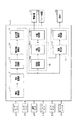
図1において、運転支援装置10は、CPU、ROM、RAM、I/O等を備えたコンピュータであり、CPUが、ROMにインストールされているプログラムを実行することでこれら各機能を実現する。運転支援装置10は、自車の周囲に存在する物体を検知する物体検知センサであるレーダセンサ21及びカメラセンサ22にそれぞれ接続されており、これらセンサから物体の検知情報を入力する。
In FIG. 1, the
レーダセンサ21は、例えばミリ波帯の高周波信号を送信波とする公知のミリ波レーダであり、自車の前端部に設けられている。レーダセンサ21は、車両前方に向かって所定範囲で広がる領域を所定時間ごとにレーダ信号で走査する。また、レーダセンサ21は、車外の物体の表面で反射された電磁波を受信することで、物体との距離、物体との相対速度等をレーダ物標情報として取得する。レーダセンサ21が取得したレーダ物標情報は運転支援装置10に入力される。
The
撮像装置としてのカメラセンサ22は、例えばCCDカメラ、CMOSイメージセンサ、近赤外線カメラである。カメラセンサ22は、車両前方における車幅方向中央の所定高さに取り付けられており、車両前方へ向けて、自車周囲の所定角度範囲で広がる領域を俯瞰視点から撮影する。カメラセンサ22が撮影した画像(以下「撮影画像」ともいう。)は運転支援装置10に入力される。
The
その他、自車には、自車の走行状態を検出する車両センサとして、車速を検出する車速センサ23、車両の旋回方向への角速度(ヨーレート)を検出するヨーレートセンサ24、ハンドル(ステアリングホイール)の操舵角を検出するステアセンサ25等の各種センサが設けられている。また、自車には、自車の進行方向を照射する照射装置である前照灯33や、前照灯33の点灯状態を自動及び手動のいずれで操作するかをドライバが設定するためのオートライトスイッチ26が設けられている。前照灯33は、照射光における光軸の車高方向の角度が調整されることにより、ロービームとハイビームとの間で切り替え可能になっている。車両センサの各種検出信号及びスイッチ類の操作信号は運転支援装置10に入力される。
In addition, the own vehicle includes a
運転支援装置10は、図1に示すように、物体検知部11、車両認識部12、歩行者認識部13、物体情報演算部14、走行状態演算部15、回避制御部16及び配光制御部17を備えている。
As shown in FIG. 1, the
物体検知部11は、レーダセンサ21からレーダ物標情報を入力する。また、カメラセンサ22から撮影画像を入力して画像処理することで、自車前方に存在する物体までの距離や、物体の形状等を画像物標情報として取得する。なお、物体検知部11は、カメラセンサ22での画像処理によって取得された画像物標情報を入力してもよい。
The
車両認識部12及び歩行者認識部13は、カメラセンサ22の撮影画像に対して、テンプレートマッチング等の周知の画像処理を行うことにより、撮影画像内に存在する物体の種別(例えば、他車両、歩行者、自転車、路上障害物等)を判別する。なお、車両認識部12及び歩行者認識部13が種別判定部として機能する。
The
物体情報演算部14は、レーダ物標情報及び画像物標情報を用いて、レーダセンサ21が検知した物標であるレーダ物標と、カメラセンサ22が検知した物標である画像物標と
が同一物体であるか否かを判定する。また、レーダ物標と画像物標とが同一物体であると判定された場合に、レーダ物標情報と画像物標情報とをフュージョンして、フュージョン物標を生成する。また、フュージョン物標の位置や速度を演算する。走行状態演算部15は、車速センサ23やヨーレートセンサ24、ステアセンサ25等の各種センサの検知信号に基づいて、自車の走行状態(例えば、自車速度やヨーレート等)を演算する。
The object
回避制御部16は、物体検知部11で検知された物体と自車との衝突を回避するための衝突回避制御を実施する。回避制御部16は、規制値演算部16aと、作動判定部16bと、作動処理部16cとを備えている。
The
規制値演算部16aは、物体検知部11によって検知された物標と自車との衝突回避時間(TTC:Time to Collision)や、衝突回避のための安全装置の作動領域における横方向の幅を定める横位置閾値を演算する。衝突回避時間とは、このままの自車速度で走行した場合に何秒後に物体に衝突するかを示す評価値である。衝突回避時間は、例えば物標と自車との距離を、物標の自車に対する相対速度で除算する等の方法により算出される。衝突回避時間は、自車速度が速いほど小さい値が設定される。
The regulation value calculation unit 16a determines the collision avoidance time (TTC: Time to Collision) between the target and the own vehicle detected by the
横位置閾値は、物体が自車に衝突することが予測される横位置範囲を示す閾値であり、例えば物標の自車に対する横方向の相対速度に基づいて算出される。規制値演算部16aにより算出された衝突回避時間や横位置閾値は作動判定部16bに入力される。
The lateral position threshold value is a threshold value indicating a lateral position range in which an object is predicted to collide with the own vehicle, and is calculated based on, for example, the relative velocity of the target in the lateral direction with respect to the own vehicle. The collision avoidance time and the lateral position threshold value calculated by the regulation value calculation unit 16a are input to the
作動判定部16bは、衝突回避時間と横位置閾値とを用いて、安全装置を作動させるか否かを判定する。本実施形態において作動判定部16bは、衝突回避時間と、安全装置の作動タイミングとを比較し、衝突回避時間が作動タイミング以下となり、かつフュージョン物標の横位置が安全装置の作動領域内に入っている場合に、安全装置を作動させる旨の指令信号を作動処理部16cに出力する。作動タイミングは、安全装置による衝突回避のための動作ごとに異なる値が予め設定され、メモリに記憶されている。
The
安全装置として本実施形態では、警報装置31とブレーキ装置32とを備えている。警報装置31は、例えば自車の車室内に設置されたスピーカやディスプレイである。ブレーキ装置32は、自車に制動力を付与する制動装置である。本実施形態では、衝突回避動作として、警報装置31を作動させる警報動作と、運転者のブレーキ操作があった場合にそのブレーキ操作による制動力を増強するブレーキアシスト動作と、車両のブレーキ装置32を自動で作動させる自動ブレーキ動作と、を実施する。
As a safety device, the present embodiment includes an
具体的には、作動判定部16bは、まず、衝突回避時間が第1閾値以下になると、警報装置31の作動を指令する指令信号を出力する。衝突回避時間が、第1閾値よりも小さい第2閾値以下になると、ブレーキアシストの作動を指令する指令信号を出力する。その後さらに、衝突回避時間が、第2閾値よりも小さい第3閾値以下になり、物体と自車とが衝突する可能性がさらに高まった場合には、自動ブレーキの作動を指令する指令信号を出力する。安全装置は、物体に対する自車の相対速度が速いほど早いタイミングで作動される。
Specifically, the
作動処理部16cは、作動判定部16bの判定結果に応じて、警報装置31及びブレーキ装置32を作動させる。なお、安全装置としてさらに、自車の各座席に設けられたシートベルトを引き込むシートベルト装置や、自動操舵を行う操舵装置等を備えていてもよい。
The
配光制御部17は、オートライトスイッチ26が「自動」に設定されている場合に、前照灯33の照射状態を自動制御する。本実施形態では、配光制御部17は、前照灯33の車高方向の光軸角度をハイビームとロービームとの間で自動的に切り替えるオートハイビーム機能を実現する。配光制御部17は、照射判定部17aと、配光処理部17bとを備えている。
The light
照射判定部17aは、前照灯33の車高方向の光軸をハイビームとロービームとの間で切り替えるための所定の切替条件が成立しているか否かを判定する。切替条件として、本実施形態では以下の条件(1)〜(3)を含む。以下の条件(1)〜(3)のいずれかが成立している場合には、前照灯33の光軸をハイビームとロービームとの間で切り替える自動切替処理を実施する。
(切替条件)
(1)車速センサ23により検出された自車速度が判定値Vth以下となった場合にはロービームに切り替える。
(2)カメラセンサ22の撮影画像から、自車の前方に自車の走行車線を走行する他車両(以下「先行車」という。)が存在することが検知されている場合にはロービームに切り替える。
(3)カメラセンサ22の撮影画像から、自車の前方に自車の対向車線を走行する他車両(以下「対向車」という。)が存在することが検知されている場合にはロービームに切り替える。
The
(Switching condition)
(1) When the own vehicle speed detected by the
(2) If it is detected from the captured image of the
(3) If it is detected from the captured image of the
自車速度が判定値Vth以下の低車速領域では、撮影画像による対向車の認識精度が低下する。この点に鑑み、本システムでは、切替条件として、「自車速度が判定値Vth以下である場合にはロービームに切り替えること」の条件を含んでいる。判定値Vthは、カメラセンサ22による対向車の検知精度を十分に確保することが可能な車速の下限値である。照射判定部17aの判定結果を示す信号は配光処理部17bに入力される。
In the low vehicle speed region where the own vehicle speed is equal to or less than the determination value Vth, the recognition accuracy of the oncoming vehicle based on the captured image is lowered. In view of this point, this system includes a condition of "switching to a low beam when the own vehicle speed is equal to or less than the determination value Vth" as a switching condition. The determination value Vth is a lower limit value of the vehicle speed that can sufficiently secure the detection accuracy of the oncoming vehicle by the
配光処理部17bは、照射判定部17aの判定結果に基づいて、前照灯33の図示しないアクチュエータを駆動することにより、車高方向の光軸をハイビームとロービームとの間で切り替える。なお、車両走行時には、前照灯33を原則ハイビームとすることで、夜間等において運転者が遠くの物体を早い段階で認識できるようにするとともに、自車から離れた他車や歩行者が自車の存在に早く気付くようにする。したがって、配光処理部17bは、自車の前方に先行車及び対向車のいずれも存在しておらず、かつ自車速度が判定値Vthよりも高い場合にはハイビームの状態を保持する。
The light distribution processing unit 17b switches the optical axis in the vehicle height direction between the high beam and the low beam by driving an actuator (not shown) of the
ここで、カメラセンサ22の物体検知範囲は、前照灯33の光軸高さに応じて異なり、ハイビームでは、ロービームよりも遠距離まで照射可能である。これにより、ハイビームのときには、より遠距離に存在する物体をカメラセンサ22で検知することができる。そのため、前照灯33をハイビームとしている状況でカメラセンサ22によって物体が検知され、その検知された物体を対象に衝突回避動作を開始した後に、前照灯33がハイビームからロービームに切り替えられた場合、衝突回避制御の対象物を見失うおそれがある。かかる場合、車両の安全確保のための運転支援制御を適切に実施できなくなることが懸念される。
Here, the object detection range of the
図2では、夕暮れや夜間、早朝等において、道路を走行している自車30の前方に歩行者51が存在する場面を時系列で示している。図2中、(a)は、自車30が判定値Vthよりも高車速で走行している場合、(b)は、(a)の走行状態で自動ブレーキが作動し、自車速度が判定値Vthよりも低車速になった場合を示している。図2では、自車30のオートライトスイッチ26は「自動」に設定されている。
FIG. 2 shows in chronological order a scene in which a
自車30の前方に先行車も対向車も存在していない場合、自車速度が判定値Vthよりも高ければ、自車30は、図2(a)に示すように、前照灯33をハイビームとした状態で走行する。この場合、前照灯33が自車30の前方遠くまで(例えば100m程度先まで)照らすことにより、カメラセンサ22による物体の検知距離が長くなる。これにより、自車30から比較的遠くにいる歩行者51についてもカメラセンサ22で検知される。また、自車30と歩行者51とが衝突する可能性がある場合には、カメラセンサ22で検知した歩行者51を対象に、衝突回避動作として、まず警報装置31が作動し、続いてブレーキアシスト及び自動ブレーキが順に作動する。
If there is neither a preceding vehicle nor an oncoming vehicle in front of the own vehicle 30 and the own vehicle speed is higher than the determination value Vth, the own vehicle 30 uses the
歩行者51との衝突を回避するべく自動ブレーキが作動して、自車速度が判定値Vth以下になった場合に、オートハイビーム機能を優先させる制御とすると、図2(b)に示すように、前照灯33がハイビームからロービームに切り替えられる。この場合、前照灯33の照射距離が短くなる。このため、カメラセンサ22の検知距離が短くなり、それまでカメラセンサ22で検知していた物体(歩行者51)をカメラセンサ22で検知できなくなることがある。また、衝突回避制御の対象物をロストしたことで、自動ブレーキが解除されることが考えられる。
As shown in FIG. 2B, if the automatic brake is activated to avoid a collision with the
そこで本実施形態では、前照灯33がハイビームとしている状況でカメラセンサ22により物体を検知し、その物体検知に基づき衝突回避動作を開始する場合には、切替条件の成否にかかわらず、前照灯33をハイビームからロービームへ切り替えることを抑制する切替抑制制御を実施することとしている。切替抑制制御として本実施形態では、自車が衝突回避動作を実施している期間では、前照灯33の切り替えを禁止する。これにより、前照灯33の切り替えに起因して衝突回避動作の対象物をロストしないようにし、自車と物体との衝突回避のための動作が途中で解除されないようにしている。
Therefore, in the present embodiment, when an object is detected by the
本実施形態の自動切替処理の具体的態様について、図3のタイムチャートを用いて説明する。図3では、自車前方に先行車も対向車も存在しておらず、ハイビームで走行中に少なくともカメラセンサ22で自車前方に歩行者が存在していることを検知した場合(図2(a)の場合)を想定している。
A specific embodiment of the automatic switching process of the present embodiment will be described with reference to the time chart of FIG. In FIG. 3, there is no preceding vehicle or oncoming vehicle in front of the vehicle, and at least the
図3中、(a)は自車速度の推移、(b)はカメラセンサ22による歩行者検知の推移、(c)は警報装置31の作動の推移、(d)はブレーキアシストの作動の推移、(e)は自動ブレーキの作動の推移、(f)は切替禁止フラグの推移、(g)は前照灯33のハイビーム/ロービームの推移をそれぞれ示している。切替禁止フラグは、ハイビームからロービームへの切り替えを禁止することを示すフラグである。切替禁止フラグは、ハイビームからロービームへの切り替えを許容する場合にオフが設定され、ハイビームからロービームへの切り替えを禁止する場合にオンが設定される。
In FIG. 3, (a) is a transition of the own vehicle speed, (b) is a transition of pedestrian detection by the
図3において、ハイビームで走行しているときに、自車30の前方にカメラセンサ22で歩行者51を検知し(時刻t10)、その後、衝突回避時間が第1閾値以下になった時刻t11で、警報装置31が作動される。その後さらに、衝突回避時間が第2閾値以下になるとブレーキアシストが作動され、衝突回避時間が第3閾値以下になった時刻t12で自動ブレーキが作動される。自動ブレーキの作動タイミングである時刻t12では、切替禁止フラグがオフからオンに切り替えられる。
In FIG. 3, when traveling with a high beam, a
自動ブレーキの作動に伴い自車30の車速が低下し、その後の時刻t13で車速が判定値Vth以下になった場合、切替禁止フラグがオンであるため、前照灯33のロービームへの切り替えは行われず、時刻t13以降ではハイビームで保持される(図3(g)の実線参照)。
If the vehicle speed of the own vehicle 30 decreases due to the operation of the automatic brake and the vehicle speed becomes less than or equal to the judgment value Vth at the subsequent time t13, the switching prohibition flag is on, so the
これに対し、オートハイビーム機能において衝突回避動作を考慮しない場合には、図3(g)に一点鎖線で示すように、車速が判定値Vth以下になった時刻t13で、つまり自動ブレーキが作動している途中で、前照灯33がハイビームからロービームに切り替えられることとなる。
On the other hand, when the collision avoidance operation is not considered in the auto high beam function, as shown by the alternate long and short dash line in FIG. 3 (g), the automatic brake is activated at the time t13 when the vehicle speed becomes the judgment value Vth or less. During the process, the
その後、自車30が歩行者51の手前で停止し、歩行者51との衝突が回避されると、衝突回避制御のための安全装置の作動が停止され、切替禁止フラグがオフに切り替えられる。これにより、前照灯33がハイビームからロービームに切り替えられる。なお、自車30の停止後も、切り替え禁止フラグをオンのままにしてハイビームを保持するようにしてもよい。
After that, when the own vehicle 30 stops in front of the
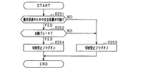
次に、本実施形態の衝突回避制御とオートハイビーム機能との協調制御について、図4及び図5のフローチャートを用いて説明する。図4の切替禁止フラグ設定処理、及び図5の自動切替処理は、オートライトスイッチ26が「自動」に設定されている場合に、運転支援装置10により所定周期毎に実行される。
Next, the cooperative control between the collision avoidance control and the auto high beam function of the present embodiment will be described with reference to the flowcharts of FIGS. 4 and 5. The switching prohibition flag setting process of FIG. 4 and the automatic switching process of FIG. 5 are executed by the driving
まず、図4を用いて、切替禁止フラグ設定処理の処理手順を説明する。図4において、ステップS201では、カメラセンサ22で検知された物体との衝突を回避するべく、安全装置が作動したか否かを判定する。安全装置の作動開始後であれば、ステップS202へ進み、自動ブレーキが作動したか否かを判定する。自動ブレーキの作動前であればステップS203へ進み、切替禁止フラグをオフにする。一方、自動ブレーキの作動タイミング以降であればステップS204へ進み、切替禁止フラグをオンにする。
First, the processing procedure of the switching prohibition flag setting process will be described with reference to FIG. In FIG. 4, in step S201, it is determined whether or not the safety device has been activated in order to avoid a collision with the object detected by the
次に、本実施形態の自動切替処理の処理手順について図5を用いて説明する。図5において、ステップS101では、車速センサ23で検出された車速が判定値Vth以下であるか否かを判定する。車速が判定値Vthよりも高ければ、ステップS101で否定判定されてステップS102へ進む。ステップS102では、自車の前方に先行車が存在しているか否かを判定する。ここでは、カメラセンサ22及びレーダセンサ21によって先行車が検知されている場合に肯定判定される。
Next, the processing procedure of the automatic switching process of the present embodiment will be described with reference to FIG. In FIG. 5, in step S101, it is determined whether or not the vehicle speed detected by the
続くステップS103では、自車の前方に対向車が存在しているか否かを判定する。ここでは、カメラセンサ22及びレーダセンサ21によって対向車が検知されている場合に肯定判定される。自車の前方に先行車及び対向車のいずれも存在していない場合には、ステップS104へ進み、前照灯33をハイビームにする。一方、自車の前方に先行車及び対向車の少なくともいずれかが存在している場合には、ステップS105へ進み、前照灯33をロービームにする。
In the following step S103, it is determined whether or not an oncoming vehicle exists in front of the own vehicle. Here, when an oncoming vehicle is detected by the
車速センサ23で検知された車速が判定値Vth以下である場合には、ステップS101で肯定判定されてステップS106へ進み、前照灯33がハイビームであるか否かを判定する。前照灯33がハイビームとなっている場合には、ステップS106で肯定判定されてステップS107へ進み、切替禁止フラグがオンか否かを判定する。切替禁止フラグがオフである場合には、一旦そのまま本ルーチンを終了する。切替禁止フラグがオンである場合にはステップS108へ進む。
When the vehicle speed detected by the
ステップS108では、カメラセンサ22で検知された物体、つまり自動ブレーキの作動対象となっている物体の種別が歩行者であるか否かを判定する。自動ブレーキの対象物が歩行者であればステップS109へ進み、ハイビームからロービームへの切り替えを禁止する。これにより、自動ブレーキの作動タイミング以降では、前照灯33の光軸の車高方向が、車速が判定値Vth以下となった場合でもハイビームの状態で保持される。
In step S108, it is determined whether or not the type of the object detected by the
一方、自動ブレーキの作動対象の物体種別が歩行者でなければ、ロービームへの切り替えを禁止せず、本ルーチンを終了する。自車が安全に歩行者を通り過ぎると、自車速度が判定値Vth以下となった場合には前照灯33がロービームに切り替えられる。
On the other hand, if the object type for which the automatic brake is operated is not a pedestrian, the switch to the low beam is not prohibited and this routine is terminated. When the own vehicle safely passes by a pedestrian, the
以上詳述した本実施形態によれば、次の優れた効果が得られる。 According to the present embodiment described in detail above, the following excellent effects can be obtained.
前照灯33をハイビームとしている状況でカメラセンサ22により物体を検知し、その検知した物体を対象に衝突回避動作を行う場合に、衝突回避動作の開始後では、ハイビームからロービームへの切替条件の成否にかかわらず、ハイビームからロービームへの切り替えを抑制する構成とした。この構成によれば、衝突回避動作の開始後も、引き続き、衝突回避制御の作動対象となっている物体を検知可能な状態を維持することができる。これにより、衝突回避制御の作動物をロストする可能性を小さくでき、その結果、衝突回避制御を適切に行うことができる。
When an object is detected by the
自動ブレーキの作動により自車速度が判定値Vthを下回った場合に、ハイビームからロービームへの切り替えを優先すると、衝突回避制御の対象物を途中で見失うおそれが高くなる。この点、本実施形態では、前照灯33をハイビームとしている状況で衝突回避動作を実施する場合には、安全装置の作動タイミング以降において、ハイビームからロービームへの切り替えを禁止する。これにより、プリクラッシュセーフティシステムとオートハイビームシステムとが協調しながら、安全性確保の観点から適切に機能するようにすることができる。
If the switching from the high beam to the low beam is prioritized when the vehicle speed falls below the determination value Vth due to the operation of the automatic brake, there is a high possibility that the object of collision avoidance control will be lost on the way. In this respect, in the present embodiment, when the collision avoidance operation is performed in the situation where the
車両認識部12及び歩行者認識部13により判定された物体の種別に基づいて、前照灯33のロービームへの切り替えを禁止するか否かを決定する構成とした。夕暮れや夜間、早朝等のように車両走行時の周囲環境が暗い状況では、カメラセンサ22によっては歩行者51を検知しにくい。そのため、衝突回避動作の開始後も、衝突回避制御の対象物を検知可能な状態を維持する必要性が高い。一方、自転車や自動二輪等は、灯火器や反射器が取り付けられているため、歩行者51ほどカメラセンサ22による検知性能は低くない。そのため、ロービームへの切り替えを優先しても、衝突回避制御を適切に実施できないといった不都合が生じにくい。
Based on the type of the object determined by the
これらの点に鑑み、本実施形態では、衝突回避制御の対象が歩行者51である場合には、衝突回避動作の開始タイミング以降においてハイビームからロービームへの切り替えを禁止し、衝突回避制御の対象が他車や自転車、自動二輪車の場合には、衝突回避動作の開始タイミング以降においてハイビームからロービームへの切り替えを許容する。これにより、物体に対する衝突回避のためのハイビーム保持と、対向車が存在する可能性のある状況でのロービームへの切り替えと、のいずれを優先させるかを、都度の状況に応じて選択することができる。
In view of these points, in the present embodiment, when the target of the collision avoidance control is the
自動ブレーキの作動タイミング以降において、ハイビームからロービームへの切り替えを禁止する構成とした。自車速度が判定値Vth以下では、カメラセンサ22の検知精度の低下に起因して、実際には対向車が存在している場合に対向車なしと認識される可能性がある。そのため、ハイビームからロービームへの切り替えを禁止する期間は必要最小限とすることが望ましい。その点、自動ブレーキが実際に作動した後をハイビームからロービームへの切替禁止期間とする上記構成によれば、衝突回避動作による車速低下であることが確実な期間にロービームへの切り替えを禁止することができる。
After the automatic brake operation timing, switching from high beam to low beam is prohibited. When the own vehicle speed is equal to or less than the determination value Vth, it may be recognized that there is no oncoming vehicle when an oncoming vehicle actually exists due to a decrease in the detection accuracy of the
(他の実施形態)
本発明は上記の実施形態に限定されず、例えば以下のように実施されてもよい。
(Other embodiments)
The present invention is not limited to the above embodiment, and may be implemented as follows, for example.
・自動ブレーキの作動タイミング以降においてハイビームからロービームへの切り替えを抑制する構成に替えて、警報装置31の作動タイミング以降において、ハイビームからロービームへの切り替えを抑制する構成としてもよい。具体的には、図3の時刻t11で警報装置31が作動した場合に、その時刻t11で切替禁止フラグをオフからオンに切り替える。そして、時刻t11以降の期間では、自車速度にかかわらず、ハイビームからロービームへの切り替えを禁止する。こうした制御によれば、その後、自車速度が判定値Vth以下になる可能性がある期間に、ロービームへの切り替えを早目に禁止しておくことができる。これにより、衝突回避動作の開始タイミング以降にハイビームからロービームへ切り替えられることをより確実に防ぐことができる。
-Instead of the configuration that suppresses the switching from the high beam to the low beam after the operation timing of the automatic brake, the configuration may suppress the switching from the high beam to the low beam after the operation timing of the
・あるいは、ブレーキアシスト機能の作動タイミング以降に、ハイビームからロービームへの切り替えを抑制する構成としてもよい。また、自動ブレーキ動作として、ブレーキ装置32を作動させて第1減速度で弱減速させる第1ブレーキと、第1ブレーキの作動後において第1減速度よりも大きい第2減速度で強減速させる第2ブレーキと、を実施する運転支援システムにおいて、第1ブレーキ又は第2ブレーキの作動タイミング以降に、ハイビームからロービームへの切り替えを抑制する構成としてもよい。
-Alternatively, it may be configured to suppress switching from the high beam to the low beam after the operation timing of the brake assist function. Further, as the automatic braking operation, the first brake that operates the
・配光制御として、先行車が照射されるように前照灯33の照射距離を自動で可変に設定する機能を有するシステムがある。このシステムでは、カメラセンサ22によって先行車が検知されている場合には、その先行車の検知位置まで前照灯33が照射するように前照灯33の照射距離を自動で設定する。また、カメラセンサ22によって先行車が検知されていない場合には、前照灯33が照射可能な最大距離を照射距離に自動で設定する。なお、最大距離は、ハイビームとロービームで異なる。こうしたシステムにおいて、衝突回避動作の開始タイミング以降では、ハイビームからロービームへの切り替えを抑制するとともに、衝突回避動作の開始タイミングでの照射距離を保持するようにしてもよい。これにより、衝突回避動作が開始された後にも、衝突回避制御の対象としている物体を検知可能な状態を維持することができる。
-As light distribution control, there is a system having a function of automatically and variably setting the irradiation distance of the
具体的には、図6において、ハイビームで走行しているときに、カメラセンサ22によって自車30の前方に歩行者51が検知され、その後、自動ブレーキが作動した場合、自動ブレーキの作動タイミングの時刻t21で、切替禁止フラグがオフからオンに切り替えられる。また、時刻t21以降では、前照灯33の照射距離が、自動ブレーキの作動タイミングでの照射距離D1で保持される。自動ブレーキの作動に伴い自車30の車速が低下し、その後の時刻t22で車速が判定値Vth以下になった場合には、前照灯33のロービームへの切り替えは行われず、ハイビームで保持される。
Specifically, in FIG. 6, when a
なお、図6では、自動ブレーキの作動タイミングでの照射距離D1を保持したが、警報装置31の作動タイミングでの照射距離を保持する構成としてもよい。例えば、前照灯33の照射距離については、警報装置31の作動タイミングでの照射距離を保持し、切替禁止フラグについては、自動ブレーキの作動タイミングでオフからオンにする。
Although the irradiation distance D1 at the operation timing of the automatic brake is maintained in FIG. 6, the irradiation distance at the operation timing of the
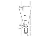
・配光制御として、前照灯33の照射方向を、カメラセンサ22で検知した物体が存在する方向に自動で切り替える機能を有するシステムがある。こうしたシステムでは、前照灯33をハイビームとしているときに衝突回避動作が実施される場合に、前照灯33による照射方向を、衝突回避動作の開始時の照射方向で保持するようにしてもよい。これにより、衝突回避動作を開始した後にも、衝突回避制御の対象物を検知可能な状態を維持することができる。
-As light distribution control, there is a system having a function of automatically switching the irradiation direction of the
前照灯33の照射方向を自動で切り替える場合の具体的態様を図7に示す。本実施形態では、カメラセンサ22によって検知されている物体の種別が歩行者である場合に限って、その物体に向けて前照灯33を照射するものとなっている。図7において、カメラセンサ22によって自車30の前方に歩行者51が検知されている場合、前照灯33の照射方向が、歩行者51の存在する方向に自動で切り替えられる。図7では、歩行者51は、自車30の進行方向に対して左側にいるため、左右の前照灯33のうち、左側の前照灯33aについて、照射方向を基準方向Poからθ1だけ左方向に傾ける。そして、前照灯33をハイビームとしているときに衝突回避動作が開始された場合には、その開始タイミング以降においてハイビームからロービームへの切り替えを禁止するとともに、前照灯33による照射方向を、衝突回避動作の開始タイミングの照射方向、つまり基準方向Poからθ1だけ左方向に傾けた向きで保持する。
FIG. 7 shows a specific mode in which the irradiation direction of the
・上記実施形態では、カメラセンサ22によって検知されている物体の種別が歩行者51であることを条件に、衝突回避動作の開始タイミング以降においてハイビームからロービームへの切り替えを抑制する構成としたが、物体の種別にかかわらず、衝突回避動作の開始タイミング以降にハイビームからロービームへの切り替えを抑制してもよい。あるいは、カメラセンサ22によって検知されている物体の種別が、歩行者51及び自転車のいずれかであることを条件に、衝突回避動作の開始タイミング以降においてハイビームからロービームへの切り替えを抑制する構成としてもよい。また、歩行者51に加え、動物(例えば犬や猫など)を含めてもよい。
-In the above embodiment, on the condition that the type of the object detected by the
・ハイビームとロービームとを切り替える切替条件として、上記の条件(1)〜(3)以外を含んでいてもよい。例えば、反射光を検出する受光センサを自車30に取り付け、受光センサによって検出される反射光が所定強度よりも大きい場合にハイビームからロービームに切り替える条件を含んでいてもよい。雪や霧などの気象環境下では、ハイビームにすると光の反射が強く、却って視認性が低下することが考えられるからである。 -The switching condition for switching between the high beam and the low beam may include conditions other than the above conditions (1) to (3). For example, it may include a condition in which a light receiving sensor for detecting reflected light is attached to the own vehicle 30 and the high beam is switched to the low beam when the reflected light detected by the light receiving sensor is larger than a predetermined intensity. This is because in a meteorological environment such as snow or fog, the high beam reflects light strongly, and it is considered that the visibility is rather lowered.
・反射光が所定強度よりも大きい場合にハイビームからロービームに自動で切り替えることを切替条件に含む場合、衝突回避動作の開始タイミング以降において、反射光が所定強度よりも大きい場合にもハイビームからロービームへ切り替えず、ハイビームの状態を保持してもよい。 -When the switching condition includes automatic switching from high beam to low beam when the reflected light is greater than the predetermined intensity, from the high beam to the low beam even when the reflected light is greater than the predetermined intensity after the start timing of the collision avoidance operation. The state of the high beam may be maintained without switching.
・切替抑制制御としては、衝突回避動作が作動している期間において、ハイビームからロービームへの切り替えを禁止する構成に替えて、ハイビームからロービームへの切り替えのタイミングを遅らせる構成を採用してもよい。具体的には、前照灯33がハイビームとしている状況でカメラセンサ22により物体を検知し、その物体検知に基づき衝突回避動作を開始した場合には、衝突回避動作が作動している期間において、前照灯33をハイビームからロービームへ切り替えるタイミングを、切替条件の成立タイミングよりも遅くする。例えば、図3において、衝突回避動作の作動中は、切替条件の成立タイミングである時刻t13よりも遅いタイミングTA(例えば、車両停止直前のタイミング)までは、ハイビームからロービームに切り替えず、タイミングTAで前照灯33をハイビームからロービームに切り替える。
-As the switching suppression control, a configuration that delays the timing of switching from the high beam to the low beam may be adopted instead of the configuration that prohibits the switching from the high beam to the low beam during the period when the collision avoidance operation is operating. Specifically, when an object is detected by the
・上記実施形態では、物体検知センサとしてカメラセンサ22とレーダセンサ21とを有する車両の運転支援システムについて説明したが、レーダセンサ21を有さない車両の運転支援システムに適用してもよい。
-In the above embodiment, the vehicle driving support system having the
・上記の各構成要素は概念的なものであり、上記実施形態に限定されない。例えば、一つの構成要素が有する機能を複数の構成要素に分散して実現したり、複数の構成要素が有する機能を一つの構成要素で実現したりしてもよい。 -Each component described above is conceptual and is not limited to the above embodiment. For example, the function of one component may be distributed to a plurality of components, or the function of the plurality of components may be realized by one component.
10…運転支援装置、11…物体検知部、16…回避制御部、17…配光制御部、22…カメラセンサ(撮像装置)、31…警報装置、32…ブレーキ装置、33…前照灯(照射装置)。 10 ... Driving support device, 11 ... Object detection unit, 16 ... Avoidance control unit, 17 ... Light distribution control unit, 22 ... Camera sensor (imaging device), 31 ... Alarm device, 32 ... Brake device, 33 ... Headlight ( Irradiation device).
Claims (6)
前記撮像装置により撮影された画像に基づいて、前記自車周囲に存在する物体を検知する物体検知部と、
前記物体検知部により検知された物体と前記車両とが衝突する可能性がある場合に、前記物体と前記車両との衝突を回避するための衝突回避制御を実施する回避制御部と、
所定の切替条件に基づいて、前記照射装置の照射光をハイビームとロービームとの間で切り替える配光制御部と、を備え、
前記所定の切替条件として、自車速度が判定値以下である場合に前記照射光をハイビームからロービームに切り替えることを含み、
前記回避制御部は、前記衝突回避制御として、前記車両のブレーキ装置を自動で作動させる自動ブレーキ動作を実施し、
前記配光制御部は、前記照射光をハイビームとしているときに前記回避制御部により前記衝突回避制御が実施される場合に、前記照射光のハイビームからロービームへの切り替えを抑制する切替抑制制御を実施し、かつ前記自動ブレーキ動作の開始後では、自車速度が前記判定値以下になった場合にも、前記切替抑制制御により前記照射光のハイビームからロービームへの切り替えを抑制してハイビームの状態を保持し続ける、運転支援装置。 It is a driving support device of a vehicle (30) including an irradiation device (33) that irradiates the traveling direction of the own vehicle and an imaging device (22) that photographs the surroundings of the own vehicle.
An object detection unit that detects an object existing around the vehicle based on an image taken by the image pickup device, and an object detection unit.
When there is a possibility that an object detected by the object detection unit collides with the vehicle, an avoidance control unit that performs collision avoidance control for avoiding a collision between the object and the vehicle, and an avoidance control unit.
A light distribution control unit that switches the irradiation light of the irradiation device between a high beam and a low beam based on a predetermined switching condition is provided.
The predetermined switching condition includes switching the irradiation light from the high beam to the low beam when the vehicle speed is equal to or less than the determination value.
The avoidance control unit performs an automatic braking operation for automatically operating the braking device of the vehicle as the collision avoidance control.
The light distribution control unit implements switching suppression control that suppresses switching of the irradiation light from the high beam to the low beam when the collision avoidance control is performed by the avoidance control unit when the irradiation light is a high beam. However, after the start of the automatic braking operation , even if the vehicle speed becomes equal to or lower than the determination value , the switching suppression control suppresses the switching of the irradiation light from the high beam to the low beam to obtain a high beam state. that continues to hold a driving support device.
前記撮像装置により撮影された画像に基づいて、前記自車周囲に存在する物体を検知する物体検知部と、
前記物体検知部により検知された物体と前記車両とが衝突する可能性がある場合に、前記物体と前記車両との衝突を回避するための衝突回避制御を実施する回避制御部と、
所定の切替条件に基づいて、前記照射装置の照射光をハイビームとロービームとの間で切り替える配光制御部と、を備え、
前記所定の切替条件として、自車速度が判定値以下である場合に前記照射光をハイビームからロービームに切り替えることを含み、
前記回避制御部は、前記衝突回避制御として、警報装置を作動させる警報動作と、前記警報動作の開始後に前記物体と前記車両との衝突の可能性がさらに高まった場合に前記車両のブレーキ装置を自動で作動させる自動ブレーキ動作と、を実施し、
前記配光制御部は、前記照射光をハイビームとしているときに前記回避制御部により前記衝突回避制御が実施される場合に、前記照射光のハイビームからロービームへの切り替えを抑制する切替抑制制御を実施し、かつ前記警報動作の開始後では、自車速度が前記判定値以下になった場合にも、前記切替抑制制御により前記照射光のハイビームからロービームへの切り替えを抑制してハイビームの状態を保持し続ける、運転支援装置。 It is a driving support device of a vehicle (30) including an irradiation device (33) that irradiates the traveling direction of the own vehicle and an imaging device (22) that photographs the surroundings of the own vehicle.
An object detection unit that detects an object existing around the vehicle based on an image taken by the image pickup device, and an object detection unit.
When there is a possibility that an object detected by the object detection unit collides with the vehicle, an avoidance control unit that performs collision avoidance control for avoiding a collision between the object and the vehicle, and an avoidance control unit.
A light distribution control unit that switches the irradiation light of the irradiation device between a high beam and a low beam based on a predetermined switching condition is provided.
The predetermined switching condition includes switching the irradiation light from the high beam to the low beam when the vehicle speed is equal to or less than the determination value.
As the collision avoidance control, the avoidance control unit applies an alarm operation for operating the alarm device and a brake device for the vehicle when the possibility of a collision between the object and the vehicle is further increased after the start of the alarm operation. Perform automatic braking and automatic braking,
The light distribution control unit implements switching suppression control that suppresses switching of the irradiation light from the high beam to the low beam when the collision avoidance control is performed by the avoidance control unit when the irradiation light is a high beam. However, after the start of the alarm operation , even when the vehicle speed becomes equal to or lower than the determination value , the switching suppression control suppresses the switching of the irradiation light from the high beam to the low beam to change the state of the high beam. that continues to hold, driving support device.
前記配光制御部は、前記種別判定部により判定された前記物体の種別に基づいて、前記切替抑制制御により前記照射光のハイビームからロービームへの切り替えを抑制するか否かを決定する、請求項1又は2に記載の運転支援装置。 A type determination unit for determining the type of the object is provided.
The claim that the light distribution control unit determines whether or not the switching of the irradiation light from the high beam to the low beam is suppressed by the switching suppression control based on the type of the object determined by the type determination unit. The driving support device according to 1 or 2.
前記配光制御部は、前記照射光をハイビームとしているときに前記回避制御部により前記衝突回避制御が実施される場合に、前記照射装置による照射距離を、前記衝突回避制御の動作開始時の照射距離で保持する、請求項1〜3のいずれか一項に記載の運転支援装置。 The irradiation distance by the irradiation device is variable,
When the collision avoidance control is performed by the avoidance control unit when the irradiation light is a high beam, the light distribution control unit sets the irradiation distance by the irradiation device to the irradiation at the start of the operation of the collision avoidance control. The driving support device according to any one of claims 1 to 3, which is held at a distance.
前記配光制御部は、前記照射光をハイビームとしているときに前記回避制御部により前記衝突回避制御が実施される場合に、前記照射装置による照射方向を、前記衝突回避制御の動作開始時の照射方向で保持する、請求項1〜4のいずれか一項に記載の運転支援装置。 The irradiation direction by the irradiation device is variable,
When the collision avoidance control is performed by the avoidance control unit when the irradiation light is a high beam, the light distribution control unit irradiates the irradiation direction by the irradiation device at the start of the operation of the collision avoidance control. The driving support device according to any one of claims 1 to 4, which is held in a direction.
前記撮像装置により撮影された画像に基づいて、前記自車周囲に存在する物体を検知するステップと、
前記検知された物体と前記車両とが衝突する可能性がある場合に、前記物体と前記車両との衝突を回避するための衝突回避制御を実施するステップと、を含み、
所定の切替条件に基づいて、前記照射装置の照射光をハイビームとロービームとの間で切り替える一方、前記照射光をハイビームとしているときに前記衝突回避制御が実施される場合に、前記照射光のハイビームからロービームへの切り替えを抑制する切替抑制制御を実施し、
前記所定の切替条件として、自車速度が判定値以下である場合に前記照射光をハイビームからロービームに切り替えることを含み、
前記衝突回避制御として、前記車両のブレーキ装置を自動で作動させる自動ブレーキ動作を実施し、
前記照射光をハイビームとしているときに前記衝突回避制御が実施される場合に、前記自動ブレーキ動作の開始後では、自車速度が前記判定値以下になった場合にも、前記切替抑制制御により前記照射光のハイビームからロービームへの切り替えを抑制してハイビームの状態を保持し続ける、車両の運転支援方法。 It is a driving support method for a vehicle (30) including an irradiation device (33) that irradiates the traveling direction of the vehicle and an imaging device (22) that photographs the surroundings of the vehicle.
A step of detecting an object existing around the own vehicle based on an image taken by the image pickup device, and
Including a step of performing collision avoidance control for avoiding a collision between the object and the vehicle when there is a possibility that the detected object and the vehicle collide with each other.
When the collision avoidance control is performed when the irradiation light of the irradiation device is switched between the high beam and the low beam based on a predetermined switching condition and the irradiation light is set to the high beam, the high beam of the irradiation light is performed. Implementation of switching suppression control that suppresses switching from to low beam,
The predetermined switching condition includes switching the irradiation light from the high beam to the low beam when the vehicle speed is equal to or less than the determination value.
As the collision avoidance control, an automatic braking operation for automatically operating the braking device of the vehicle is performed.
When the collision avoidance control is performed when the irradiation light is a high beam, even if the own vehicle speed becomes equal to or less than the determination value after the start of the automatic braking operation, the switching suppression control is performed. that continues to hold the high-beam state by suppressing the switching to the low beam from the high beam of the illumination light, a driving support method for a vehicle.
Priority Applications (5)
| Application Number | Priority Date | Filing Date | Title |
|---|---|---|---|
| JP2017055069A JP6839006B2 (en) | 2017-03-21 | 2017-03-21 | Vehicle driving support device and driving support method |
| CN201880019425.3A CN110461652B (en) | 2017-03-21 | 2018-02-28 | Vehicle driving support device and driving support method |
| PCT/JP2018/007640 WO2018173674A1 (en) | 2017-03-21 | 2018-02-28 | Driving assistance device and driving assistance method for vehicles |
| DE112018001507.6T DE112018001507T5 (en) | 2017-03-21 | 2018-02-28 | VEHICLE ASSISTANCE DEVICE FOR A VEHICLE AND ASSISTANCE METHOD FOR THIS |
| US16/575,692 US11634121B2 (en) | 2017-03-21 | 2019-09-19 | Driving assistance apparatus and driving assistance method for vehicle |
Applications Claiming Priority (1)
| Application Number | Priority Date | Filing Date | Title |
|---|---|---|---|
| JP2017055069A JP6839006B2 (en) | 2017-03-21 | 2017-03-21 | Vehicle driving support device and driving support method |
Publications (3)
| Publication Number | Publication Date |
|---|---|
| JP2018154313A JP2018154313A (en) | 2018-10-04 |
| JP2018154313A5 JP2018154313A5 (en) | 2019-06-20 |
| JP6839006B2 true JP6839006B2 (en) | 2021-03-03 |
Family
ID=63585363
Family Applications (1)
| Application Number | Title | Priority Date | Filing Date |
|---|---|---|---|
| JP2017055069A Active JP6839006B2 (en) | 2017-03-21 | 2017-03-21 | Vehicle driving support device and driving support method |
Country Status (5)
| Country | Link |
|---|---|
| US (1) | US11634121B2 (en) |
| JP (1) | JP6839006B2 (en) |
| CN (1) | CN110461652B (en) |
| DE (1) | DE112018001507T5 (en) |
| WO (1) | WO2018173674A1 (en) |
Families Citing this family (4)
| Publication number | Priority date | Publication date | Assignee | Title |
|---|---|---|---|---|
| JP7044000B2 (en) * | 2018-07-20 | 2022-03-30 | 株式会社デンソー | Vehicle control device and vehicle control method |
| EP3882076A4 (en) * | 2018-11-12 | 2022-05-04 | Koito Manufacturing Co., Ltd. | Vehicular lamp system |
| JP2022052142A (en) | 2020-09-23 | 2022-04-04 | スタンレー電気株式会社 | Vehicular head lamp system, and control method of vehicular head lamp system |
| JP7165230B2 (en) * | 2021-03-31 | 2022-11-02 | 本田技研工業株式会社 | LIGHT DISTRIBUTION CONTROL DEVICE, LIGHT DISTRIBUTION CONTROL METHOD, AND PROGRAM |
Family Cites Families (20)
| Publication number | Priority date | Publication date | Assignee | Title |
|---|---|---|---|---|
| JPH01275233A (en) | 1988-04-27 | 1989-11-02 | Nissan Motor Co Ltd | Headlight device for vehicle |
| JP3325637B2 (en) * | 1993-03-26 | 2002-09-17 | マツダ株式会社 | Vehicle rear warning system |
| JPH07277115A (en) | 1994-04-15 | 1995-10-24 | Honda Motor Co Ltd | Travel supporting device for vehicle |
| EP0677799B1 (en) | 1994-04-15 | 2000-05-17 | Honda Giken Kogyo Kabushiki Kaisha | Vehicle travel aiding device |
| JP2005047383A (en) * | 2003-07-29 | 2005-02-24 | Daihatsu Motor Co Ltd | Drive assisting device |
| JP4349410B2 (en) * | 2006-12-01 | 2009-10-21 | トヨタ自動車株式会社 | Vehicle lighting device |
| JP2008189276A (en) * | 2007-02-08 | 2008-08-21 | Koito Mfg Co Ltd | Vehicular lamp system |
| JP4840203B2 (en) * | 2007-03-15 | 2011-12-21 | マツダ株式会社 | Vehicle driving support device |
| JP2008226140A (en) * | 2007-03-15 | 2008-09-25 | Mazda Motor Corp | Vehicle operation support system |
| JP2009255639A (en) | 2008-04-14 | 2009-11-05 | Denso Corp | Automatic lighting device for vehicle |
| JP4675395B2 (en) * | 2008-05-19 | 2011-04-20 | 三菱電機株式会社 | Vehicle alarm device |
| US9469242B2 (en) * | 2011-07-28 | 2016-10-18 | Denso Corporation | Headlamp light distribution control device |
| EP2653346B1 (en) * | 2012-04-16 | 2020-06-10 | Volvo Car Corporation | Vehicle safety illumination arrangement and method |
| KR101358423B1 (en) * | 2012-08-31 | 2014-02-04 | 주식회사 에스엘 서봉 | System and method for controlling automotive head lamp |
| JP5966783B2 (en) * | 2012-09-07 | 2016-08-10 | 株式会社デンソー | Vehicular headlamp control device and control method therefor |
| JP5723417B2 (en) | 2013-06-26 | 2015-05-27 | 富士重工業株式会社 | Vehicle headlamp |
| JP2015009647A (en) | 2013-06-28 | 2015-01-19 | 株式会社デンソー | Vehicle light distribution control device |
| JP6264909B2 (en) | 2014-01-31 | 2018-01-24 | 株式会社デンソー | Headlamp control device and headlamp |
| EP3262473B1 (en) * | 2015-02-26 | 2018-12-12 | Volvo Truck Corporation | Method of controlling inter-vehicle gap(s) in a platoon |
| JP6623632B2 (en) | 2015-09-11 | 2019-12-25 | 日立化成株式会社 | Insulating resin film and multilayer printed wiring board |
-
2017
- 2017-03-21 JP JP2017055069A patent/JP6839006B2/en active Active
-
2018
- 2018-02-28 DE DE112018001507.6T patent/DE112018001507T5/en active Pending
- 2018-02-28 WO PCT/JP2018/007640 patent/WO2018173674A1/en active Application Filing
- 2018-02-28 CN CN201880019425.3A patent/CN110461652B/en active Active
-
2019
- 2019-09-19 US US16/575,692 patent/US11634121B2/en active Active
Also Published As
| Publication number | Publication date |
|---|---|
| DE112018001507T5 (en) | 2020-01-09 |
| US20200010079A1 (en) | 2020-01-09 |
| WO2018173674A1 (en) | 2018-09-27 |
| US11634121B2 (en) | 2023-04-25 |
| JP2018154313A (en) | 2018-10-04 |
| CN110461652A (en) | 2019-11-15 |
| CN110461652B (en) | 2023-05-05 |
Similar Documents
| Publication | Publication Date | Title |
|---|---|---|
| US10503985B2 (en) | Pedestrian determination method and determination device | |
| JP6539228B2 (en) | Vehicle control device and vehicle control method | |
| JP6327244B2 (en) | Vehicle control device | |
| CN108541325B (en) | Driving support device and driving support method | |
| JP6839006B2 (en) | Vehicle driving support device and driving support method | |
| JP5413511B2 (en) | Vehicle light distribution control device and method | |
| JP6412457B2 (en) | Driving support device and driving support method | |
| US20170349212A1 (en) | Driving assistance device | |
| JP6729282B2 (en) | Vehicle control device | |
| WO2016208309A1 (en) | Vehicle control device and vehicle control method | |
| CN108622085B (en) | Collision avoidance device | |
| JP6491596B2 (en) | Vehicle control apparatus and vehicle control method | |
| JP6669090B2 (en) | Vehicle control device | |
| JP2005186813A (en) | Drive assisting device for vehicle | |
| JP2015009647A (en) | Vehicle light distribution control device | |
| JP6516336B2 (en) | Driving support device | |
| US20200353919A1 (en) | Target detection device for vehicle | |
| JP4926859B2 (en) | Vehicle driving support device | |
| WO2013180111A1 (en) | Device and method for controlling illumination range of vehicle light | |
| JP5195390B2 (en) | Front irradiation automatic control device | |
| CN113544031A (en) | Driving support device | |
| JP6535537B2 (en) | Driving support device for vehicle | |
| JP2009184640A (en) | Headlight device of vehicle | |
| KR20160123110A (en) | Autonomous emergency braking system | |
| JP4294450B2 (en) | Vehicle driving support device |
Legal Events
| Date | Code | Title | Description |
|---|---|---|---|
| A521 | Request for written amendment filed |
Free format text: JAPANESE INTERMEDIATE CODE: A523 Effective date: 20190514 |
|
| A621 | Written request for application examination |
Free format text: JAPANESE INTERMEDIATE CODE: A621 Effective date: 20190514 |
|
| A131 | Notification of reasons for refusal |
Free format text: JAPANESE INTERMEDIATE CODE: A131 Effective date: 20200616 |
|
| A521 | Request for written amendment filed |
Free format text: JAPANESE INTERMEDIATE CODE: A523 Effective date: 20200811 |
|
| TRDD | Decision of grant or rejection written | ||
| A01 | Written decision to grant a patent or to grant a registration (utility model) |
Free format text: JAPANESE INTERMEDIATE CODE: A01 Effective date: 20210119 |
|
| A61 | First payment of annual fees (during grant procedure) |
Free format text: JAPANESE INTERMEDIATE CODE: A61 Effective date: 20210212 |
|
| R150 | Certificate of patent or registration of utility model |
Ref document number: 6839006 Country of ref document: JP Free format text: JAPANESE INTERMEDIATE CODE: R150 |
|
| R250 | Receipt of annual fees |
Free format text: JAPANESE INTERMEDIATE CODE: R250 |