EP1969995A1 - Dispositif d'examen oculaire - Google Patents
Dispositif d'examen oculaire Download PDFInfo
- Publication number
- EP1969995A1 EP1969995A1 EP07405084A EP07405084A EP1969995A1 EP 1969995 A1 EP1969995 A1 EP 1969995A1 EP 07405084 A EP07405084 A EP 07405084A EP 07405084 A EP07405084 A EP 07405084A EP 1969995 A1 EP1969995 A1 EP 1969995A1
- Authority
- EP
- European Patent Office
- Prior art keywords
- eye
- examination device
- examination
- image
- generating
- Prior art date
- Legal status (The legal status is an assumption and is not a legal conclusion. Google has not performed a legal analysis and makes no representation as to the accuracy of the status listed.)
- Pending
Links
Images

Classifications
-
- A—HUMAN NECESSITIES
- A61—MEDICAL OR VETERINARY SCIENCE; HYGIENE
- A61B—DIAGNOSIS; SURGERY; IDENTIFICATION
- A61B3/00—Apparatus for testing the eyes; Instruments for examining the eyes
- A61B3/10—Objective types, i.e. instruments for examining the eyes independent of the patients' perceptions or reactions
- A61B3/102—Objective types, i.e. instruments for examining the eyes independent of the patients' perceptions or reactions for optical coherence tomography [OCT]
-
- G—PHYSICS
- G01—MEASURING; TESTING
- G01N—INVESTIGATING OR ANALYSING MATERIALS BY DETERMINING THEIR CHEMICAL OR PHYSICAL PROPERTIES
- G01N21/00—Investigating or analysing materials by the use of optical means, i.e. using sub-millimetre waves, infrared, visible or ultraviolet light
- G01N21/17—Systems in which incident light is modified in accordance with the properties of the material investigated
- G01N21/47—Scattering, i.e. diffuse reflection
- G01N21/4795—Scattering, i.e. diffuse reflection spatially resolved investigating of object in scattering medium
Definitions
- the invention relates to an examination device for examining an eye with a first device for generating an image of the eye, wherein the first device comprises a microscope and a lighting unit for illuminating the eye. Furthermore, the invention relates to a method for examining an eye with an examination device, wherein with a first device, an image of the eye is generated by the eye illuminated with a lighting unit and the image is generated with a microscope.
- Different physical methods are used to observe and document the fundus.
- fundus photography or examinations with an SDO only reflected light from the surface of the fundus is detected.
- Lower-lying structures can be represented by the use of different wavelengths of illumination or confocal optics.
- the doctor can already recognize a variety of pathologies due to the image information from the surface. Additional information can be found in the topography of the fundus. This is made possible, for example, when using a binocular tube which gives a stereoscopic impression.
- the object of the invention is to provide a device belonging to the technical field mentioned above, which allows a simplified examination of different eye sections, in particular the fundus and the underlying fundus structures.
- An examination device for examination comprises a first device for generating a Image of the eye, wherein the first device comprises a microscope and a lighting unit for illuminating the eye.
- the examination device comprises a second device for generating an image of a first eye section and a third device for generating a depth-resolved image of a second eye section.
- the image of the first eye section can be generated by means of a sequential scanning of the first eye section with a light beam, and with the third device a sectional view of the second eye section can be generated parallel to an optical axis of the examination device.
- the second eye portion may be different from the first eye portion.
- the second eye section is preferably a partial area of the first eye section.
- the first device is a so-called slit lamp microscope with a corresponding, lateral slit illumination, with which a narrow, slit-shaped light beam can be generated.
- the second device is in particular a so-called SDO (scanning digital ophthalmoscope) and the third device is in particular an OCT (optical coherence tomograph), d.
- SDO scanning digital ophthalmoscope
- OCT optical coherence tomograph
- H an apparatus for performing an optical coherence tomography.
- This is preferably modern spectral optical coherence tomography (SDOCT - spectral domain optical coherence tomography).
- SDOCT spectral optical coherence tomography
- the joint use of the SDO and an SDOCT allows an extended examination possibility, which can be carried out on the same examination device.
- the SDO provides the examiner with first important information on possible pathologies on the retina.
- the SDOCT now allows the scanning of sites of interest on the fundus without the patient having to be relocated to another examination device.
- the area to be scanned is visualized with a line projected on the fundus.
- the deflection unit 40 With the deflection unit 40 , the position is determined.
- the light source for the fixation aid of the patient is preferably a visible one Laser source 2, which passes through the 2x2 coupler 162 in the fiber 14b and thus on the same beam path as the measuring beam of the SDOCT on the area to be examined.
- Fixation laser 2 and measuring laser 1 are thus always congruent.
- the target area of the measuring laser could also be synthetically superimposed on the SDO image in an alternative solution, depending on the position of the translator by the software.
- B-scans are also interesting for the anterior segment of the eye, especially in the area of the posterior chamber of the eye and the ciliary body (chamber angle).
- the ophthalmoscope lens 13 For examinations in the anterior region of the eye, the ophthalmoscope lens 13 must not be interposed.
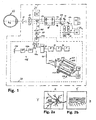
- Fig.1 shows the overall structure of the examination device, with a typical beam path of a slit lamp microscope for examining the front and rear eye portion of an eye.
- two parallel beam paths 10a lead to a 2-axis magnification changer 11. Both of the beams running in parallel have a focus set to infinity.
- the beam pair 10b which continues to run in parallel, reaches the front lens 12 of the microscope.
- the front lens 12 focuses the rays on the cornea of the subject 22.
- an ophthalmoscope lens 13 By an optional interposition of an ophthalmoscope lens 13 and a correspondingly optimized distance from the eye, the focal point lies on the fundus.
- a SDOCT 24 is coupled via a movable optical deflection unit 40 .
- the beam 3f of the SDOCT extends between the optical observation beam paths 10b to the object 22.
- the beam of the SDOCT can also be guided laterally offset over one of the observation beam paths 10b .
- the 3x magnification changer 11 has a second pair of beams rotated by 90 degrees. Via this second beam pair, an illumination and an observation beam of the SDO 23 are coupled in via two mirrors 18 and 19 .
- a lens combination 20a or 20b optionally inserted between mirror 18 or 19 and magnification changer (Galilean optics) 11 , the beams of the two optical systems 11 and 31 or 32 can be optimally adapted to each other.
- the two beams 17a and 17b are guided by the Galileiwechsler 11 , where depending on the rotational position of that different magnifications arise.
- the Galileiwechslers 11 In direct continuation of the Galileiwechslers 11 lead the parallel beam paths through the front lens 12 of the microscope and an alternately connected therebetween ophthalmoscope 13 to the object 22nd
- the SDO 23 has two optical paths 17a and 17b.
- the light of the light source 33 passes via an optical system 31 as a light beam 17a to the magnification changer 11 and on the previously described path to the object 22.
- the light component reflected by the object 22 passes on the second beam path via the magnification changer 11, which is optional Inserted lens combination 20b, the mirror 19, the lens combination 32 to the image sensor 34. With the swing stop 35 disturbing scattered lights are largely eliminated.
- the image information of the sensor 34 is supplied to an evaluation unit.
- the spectrometer 163 has a lens 164 which collimates the radiation 165 exiting the radiation guide 161 .
- the collimated radiation 167 is directed to a grating 169 .
- the grating 169 reflects each wavelength included in the radiation 167 impinging on a grating 169 in a different direction.
- This radiation 170 which is decomposed according to the wavelength components, is focused by means of a focusing lens 171 onto the camera line 159 having the camera pixels 157 . Each pixel 157 thus always receives only a very specific wavelength range.
- the positions of the various reflections in the object 22 along the propagation direction of the measurement beam 3g of the radiation source 1 can be determined.
- the reference arm 176 is connected to the coupler 160 via a monomode fiber 177a .
- the other end of the monomode fiber 177a is provided with an optional, e.g. B. piezoelectrically operating phase modulator 179 and this connected via a single-mode fiber 177 b with an optional polarization controller 180 .
- the radiation reaches a mirror 181, from which the radiation is again reflected back to the coupler 160 via the previously mentioned components.
- the radiation reflected back from the object 22 is superimposed with the radiation reflected by the reference arm 176 . Then go 50% of the radiation in the radiation conductor 161 from the fiber coupler 160th
- the SDOCT 24 contains the radiation source 1, the radiation attenuator 5 (optional), the polarization controller 7, the 2x2 monomode fiber coupler 160, the spectrometer 163, the fixation laser 2 (optional, the fixation Laser / pilot laser 2 is optional, because the radiation source 1 and in the near infrared possibly enough already visible to the patient), the reference arm 176, the polarization controller 18, the ferrule 57, the lens 183, the deflection unit 40, the drive unit 41 for the movable deflection unit 40, the lens combination 12 and 13 and the object 22.
- the constructed according to the Michelson principle interferometer can be both fiber optic and as geometric optics, ie without fibers but with a beam splitter cube instead of a 2x2 fiber coupler and a free jet instead of fibers built.
- the deflection unit 40 is movably provided as a translator. If a translator 40 is used together with a structure without fibers, even a 3-D scan can be achieved.
- a fundus image of the SDO is visible.
- a navigable brand is visible. This is either synthetic, superimposed by the software, the SDO image or with an additional LASER source, along the SDOCT beam path on the fundus imaged.
- a depth scan of an SDOCT is shown.
- the penetration depth is about 3mm.
- the length of the SDOCT B scan is determined inter alia by the deflection of the movable deflection unit 40 .
- At least 3 light sources are arranged in a plane around the front lens 12 of the slit lamp in a plane.
- the ring of these light sources is arranged concentrically to the measuring beam 3g of the SDOCT.
- the light sources can optionally be placed behind a diffuser.
- the light beams of the LEDs are reflected on the tear film of the examined eye 22 .
- the reflection on the tear film leads to the emergence of virtual images of the LEDs 200 within the eye.
- the locations of the virtual images of the LEDs are typically located a few millimeters behind the tear film, depending on the surface curvature of the tear film.
- the SDO maps the virtual images of the LEDs 200 to the image sensor 34 .
- Fig. 3 shows an embodiment with 8 LEDs, which are shown on the image sensor 34 . From the coordinates of the focal points> 201 of the LED images imaged on the image sensor 34 For example, a center 202 may be calculated. With the help of the light source 2 , the patient is instructed to look in a certain direction (fixation direction). Whether the patient is well fixed, z. B. be checked by the presence and the amplitude of the signals of the SDOCT are evaluated in the evaluation unit 173 . Possible structures that the SDOCT measures are the anterior surface of the cornea, the surface of the cornea, the anterior surface of the lens, the surface of the lens and the retina. Instead of an SDOCT, a time-domain OCT (TDOCT) can also be used.
- TDOCT time-domain OCT
- the image sensor 34 evaluates the pupil centroid 210 of the pupil 209 .
- the vector of the connecting line 211 between the pupil centroid 210 and the calculated center of the LEDs 202 is calculated.
- the length and direction of the connecting line 211 must be during the
- a photorefractive surgical intervention eg LASIK, LASEK, PRK
- Planning of a photorefractive surgical intervention are taken into account, because the corneal laser ablation pattern of today's conventional laser systems is centered on the pupillary centroid 210 . If, however, the visual axis does not pass through the center of gravity of the pupil 210 , as is often the case, then a certain error of the postoperative result is always accepted. Large distances between the center of the LEDs 202 and the pupil centroid 210 must be considered in the ablation to achieve a satisfactory postoperative refraction of the patient.
- the curvature of the anterior corneal surface can be measured by evaluating the distances of the LED centroids 201 mapped to the image sensor 34 with respect to one another. It is true that the radii of curvature increase with increasing distance between two LED centers 201 .
- the exact relationship between the radii of curvature and the LED centroids 201 is given by the position of the LEDs 200 disposed annularly on the slit lamp , the optics, and the geometry between the patient cornea and the image sensor 34. This relationship may be calculated and / or by means of a Method of calibration can be determined.
- the lens can be used to determine the radius of curvature of the flat and the radius of curvature of the steep meridian of the anterior corneal surface.
- the difference between the radii of curvature of the steep and flat meridians gives the astigmatism.
- the evaluation of the LED centroids on the image sensor 34 also yields the angle alpha between the horizontal axis of the image sensor 34 and the axis of the flat or steep meridian.
- the pattern of the iris imaged on the image sensor 34 is evaluated.
- the result of the evaluation of the iris pattern is to provide the angular position beta of a characteristic structure in the pattern of the iris with respect to the horizontal axis of the image sensor 34 .
- the angle gamma between the flat meridian (or the steep meridian) and the angular position of the characteristic iris structure can be calculated. It is assumed that the angle gamma for one and the same patient is firstly constant over time and secondly independent of the position of the patient (sitting or lying).
- This angle gamma must be known z. B. in photorefractive ablation z. B. by an excimer laser.
- Reason: Alpha can not be measured during the Excimerlaser anger because the excimer laser no necessary device z. B. in the form of LEDs 200 has.
- beta can be measured online by the excimer laser integrated eyetracker camera during the excimer laser treatment. Now, if beta is measured by the eye tracker camera and gamma is known, then the position of the flat or steep meridian alpha during the treatment can now be determined.
- the display unit 174 (see Fig. 1 ) is used to display the patient data, the positioning required for the positioning of the eye area to be measured, marks produced by software as a positioning aid and the measurement results.
- FIGS. 4a and 4b each show a brand created by software as a positioning aid.
- This can, for. B. a preferably displayed in the center of the eye area shown circle 175 whose diameter decreases with increasing signal strength of the detected by the evaluation unit 173 reflections of the SDOCTs.
- the color of the circle can change as soon as the signals are so high that they are considered reliable.
- the signals can also originate from a time-domain OCT.
- the diameter of the circle 175 may also be controlled based on the signal strength or sharpness of the image of the fundus or the anterior segment of the eye detected by the image sensor 34 .
- the diameter of the circle 175 can be regulated on the basis of the signal strength or sharpness of the LED images detected by the image sensor 34 .
- a control combination of the signal strengths or image sharpness of the SDOCT, the SDO observation field and the LED images detected by the SDO can also be selected.
- Fig. 4a shows a large circle 175, which means that the measurement signal is low. As a result, the user knows that he has to position the measuring device even better to the patient's eye.
- Fig. 4b shows a small circle 175.
- the measurement signal is strong and therefore reliable. The user knows that he can trigger the measurement because the signals are reliable.
Landscapes
- Health & Medical Sciences (AREA)
- Life Sciences & Earth Sciences (AREA)
- Physics & Mathematics (AREA)
- General Health & Medical Sciences (AREA)
- Surgery (AREA)
- Public Health (AREA)
- Ophthalmology & Optometry (AREA)
- Engineering & Computer Science (AREA)
- Biomedical Technology (AREA)
- Heart & Thoracic Surgery (AREA)
- Medical Informatics (AREA)
- Molecular Biology (AREA)
- Radiology & Medical Imaging (AREA)
- Animal Behavior & Ethology (AREA)
- Nuclear Medicine, Radiotherapy & Molecular Imaging (AREA)
- Biophysics (AREA)
- Veterinary Medicine (AREA)
- Optics & Photonics (AREA)
- Chemical & Material Sciences (AREA)
- Analytical Chemistry (AREA)
- Biochemistry (AREA)
- General Physics & Mathematics (AREA)
- Immunology (AREA)
- Pathology (AREA)
- Eye Examination Apparatus (AREA)
Priority Applications (1)
| Application Number | Priority Date | Filing Date | Title |
|---|---|---|---|
| EP07405084A EP1969995A1 (fr) | 2007-03-14 | 2007-03-14 | Dispositif d'examen oculaire |
Applications Claiming Priority (1)
| Application Number | Priority Date | Filing Date | Title |
|---|---|---|---|
| EP07405084A EP1969995A1 (fr) | 2007-03-14 | 2007-03-14 | Dispositif d'examen oculaire |
Publications (1)
| Publication Number | Publication Date |
|---|---|
| EP1969995A1 true EP1969995A1 (fr) | 2008-09-17 |
Family
ID=38255511
Family Applications (1)
| Application Number | Title | Priority Date | Filing Date |
|---|---|---|---|
| EP07405084A Pending EP1969995A1 (fr) | 2007-03-14 | 2007-03-14 | Dispositif d'examen oculaire |
Country Status (1)
| Country | Link |
|---|---|
| EP (1) | EP1969995A1 (fr) |
Cited By (2)
| Publication number | Priority date | Publication date | Assignee | Title |
|---|---|---|---|---|
| DE202009002387U1 (de) | 2008-12-22 | 2010-05-12 | Maiorova, Tatiana, Dmitrov | Optische Anordnung zum Ändern eines Abbildungsverhältnisses oder einer Brechkraft |
| DE102008064512A1 (de) | 2008-12-22 | 2010-06-24 | Maiorova, Tatiana, Dmitrov | Optische Anordnung zum Ändern eines Abbildungsverhältnisses oder einer Brechkraft |
Citations (11)
| Publication number | Priority date | Publication date | Assignee | Title |
|---|---|---|---|---|
| US5009498A (en) * | 1990-03-20 | 1991-04-23 | Computed Anatomy Inc. | Interchangeable keratoscope device |
| US5418582A (en) * | 1993-10-15 | 1995-05-23 | Lions Eye Institute Perth | Photokeratoscope apparatus and method |
| US5975697A (en) * | 1998-11-25 | 1999-11-02 | Oti Ophthalmic Technologies, Inc. | Optical mapping apparatus with adjustable depth resolution |
| EP1231496A2 (fr) * | 1994-08-18 | 2002-08-14 | Carl Zeiss | Appareil chirurgical assisté par tomographie avec cohérence optique |
| WO2004113958A2 (fr) * | 2003-06-16 | 2004-12-29 | Visx, Incorporated | Procedes et dispositifs pour enregistrer des ensembles de donnees de mesure optique dans un systeme optique |
| US20050140984A1 (en) * | 2003-12-31 | 2005-06-30 | Hitzenberger Christoph K. | Efficient optical coherence tomography (OCT) system and method for rapid imaging in three dimensions |
| US20050174537A1 (en) * | 2003-10-24 | 2005-08-11 | Nevyas Herbert J. | Ophthalmic operative keratometer with movable fixation/centration device |
| WO2006058735A1 (fr) * | 2004-12-02 | 2006-06-08 | Carl Zeiss Meditec Ag | Tomographie a coherence optique amelioree pour cartographie anatomique |
| US20060158655A1 (en) * | 2005-01-20 | 2006-07-20 | Everett Matthew J | Apparatus and method for combined optical-coherence-tomographic and confocal detection |
| US20060176448A1 (en) * | 1999-11-01 | 2006-08-10 | Van De Velde Frans J | Relaxed confocal catadioptric scanning laser ophthalmoscope |
| GB2429522A (en) * | 2005-08-26 | 2007-02-28 | Univ Kent Canterbury | Optical mapping apparatus |
-
2007
- 2007-03-14 EP EP07405084A patent/EP1969995A1/fr active Pending
Patent Citations (11)
| Publication number | Priority date | Publication date | Assignee | Title |
|---|---|---|---|---|
| US5009498A (en) * | 1990-03-20 | 1991-04-23 | Computed Anatomy Inc. | Interchangeable keratoscope device |
| US5418582A (en) * | 1993-10-15 | 1995-05-23 | Lions Eye Institute Perth | Photokeratoscope apparatus and method |
| EP1231496A2 (fr) * | 1994-08-18 | 2002-08-14 | Carl Zeiss | Appareil chirurgical assisté par tomographie avec cohérence optique |
| US5975697A (en) * | 1998-11-25 | 1999-11-02 | Oti Ophthalmic Technologies, Inc. | Optical mapping apparatus with adjustable depth resolution |
| US20060176448A1 (en) * | 1999-11-01 | 2006-08-10 | Van De Velde Frans J | Relaxed confocal catadioptric scanning laser ophthalmoscope |
| WO2004113958A2 (fr) * | 2003-06-16 | 2004-12-29 | Visx, Incorporated | Procedes et dispositifs pour enregistrer des ensembles de donnees de mesure optique dans un systeme optique |
| US20050174537A1 (en) * | 2003-10-24 | 2005-08-11 | Nevyas Herbert J. | Ophthalmic operative keratometer with movable fixation/centration device |
| US20050140984A1 (en) * | 2003-12-31 | 2005-06-30 | Hitzenberger Christoph K. | Efficient optical coherence tomography (OCT) system and method for rapid imaging in three dimensions |
| WO2006058735A1 (fr) * | 2004-12-02 | 2006-06-08 | Carl Zeiss Meditec Ag | Tomographie a coherence optique amelioree pour cartographie anatomique |
| US20060158655A1 (en) * | 2005-01-20 | 2006-07-20 | Everett Matthew J | Apparatus and method for combined optical-coherence-tomographic and confocal detection |
| GB2429522A (en) * | 2005-08-26 | 2007-02-28 | Univ Kent Canterbury | Optical mapping apparatus |
Non-Patent Citations (1)
| Title |
|---|
| SHULIANG JIAO ET AL: "Simultaneous acquisition of sectional and fundus ophthalmic images with spectral-domain optical coherence tomography", 24 January 2005, OPTICS EXPRESS, OPTICAL SOCIETY OF AMERICA, WASHINGTON, DC,, US, PAGE(S) 444-452, ISSN: 1094-4087, XP002370566 * |
Cited By (4)
| Publication number | Priority date | Publication date | Assignee | Title |
|---|---|---|---|---|
| DE202009002387U1 (de) | 2008-12-22 | 2010-05-12 | Maiorova, Tatiana, Dmitrov | Optische Anordnung zum Ändern eines Abbildungsverhältnisses oder einer Brechkraft |
| DE102008064512A1 (de) | 2008-12-22 | 2010-06-24 | Maiorova, Tatiana, Dmitrov | Optische Anordnung zum Ändern eines Abbildungsverhältnisses oder einer Brechkraft |
| WO2010072218A1 (fr) | 2008-12-22 | 2010-07-01 | Future Optics Gbr | Système optique permettant de modifier un rapport de reproduction ou une réfringence |
| US8615143B2 (en) | 2008-12-22 | 2013-12-24 | Future Optics Gbr | Optical arrangement for varying an imaging ratio or of a refractive power |
Similar Documents
| Publication | Publication Date | Title |
|---|---|---|
| DE69528024T2 (de) | Mit optischer Kohärenz-Tomographie gesteuerter chirurgischer Apparat | |
| DE69519355T2 (de) | Optisches Kohärenz-Tomographie-Gerät zur Darstellung der Kornea | |
| DE102016001659B4 (de) | Augenoperationsmikroskop und Augenoperationszusatzgerät | |
| EP1494575B1 (fr) | Mesure de proprietes optiques | |
| EP2445387B1 (fr) | Dispositif de contrôle de fixation et procédé destiné au contrôle de la fixation d'un oeil | |
| EP2799002B1 (fr) | Procédé et système d'analyse pour l'examen des yeux | |
| WO2018083323A1 (fr) | Procédé d'auto-examen d'un œil et dispositif d'auto-examen ophtalmologique | |
| WO2016041640A1 (fr) | Système de tomographie par cohérence optique comprenant un système kepler zoomable | |
| WO2017135016A1 (fr) | Dispositif ophtalmologique et système d'examen ophtalmologique | |
| WO2010031540A2 (fr) | Système de mesure utilisé en chirurgie ophtalmologique | |
| DE112017000673T5 (de) | Ophthalmologisches Gerät und Ophthalmologisches Untersuchungssystem | |
| DE102014010350A1 (de) | Augenchirurgiesystem | |
| WO2012084170A9 (fr) | Dispositif de mesure par interférométrie de la longueur de l'œil et de la partie antérieure de l'œil | |
| EP3585245B1 (fr) | Procédé et dispositif pour la topographie à haute résolution de la cornée d'un oeil | |
| JP7368581B2 (ja) | 眼科装置、及び眼科情報処理装置 | |
| DE102007047460A1 (de) | Vorrichtung und Verfahren zur Untersuchung des Augenhintergrundes, inbesondere der Photorezeptoren | |
| WO2017191128A1 (fr) | Mesure de longueur ophtalmique par interférométrie à faible cohérence à double faisceau à accord en longueur d'ondes de domaines espace-temps | |
| EP1624795A2 (fr) | Procede et dispositif permettant de mesurer la section oculaire anterieure | |
| DE102007027683A1 (de) | Vorrichtung und Verfahren zur Bestimmung von Vorderkammertiefe und Augenlänge eines Auges | |
| EP1969995A1 (fr) | Dispositif d'examen oculaire | |
| EP2621330B1 (fr) | Procédé et dispositif pour la détermination interférométrique de différents paramètres biométriques d'un il | |
| JP2021191552A (ja) | 眼科検査装置 | |
| JP2018114230A (ja) | 眼科装置 | |
| JP2020195883A (ja) | 眼科検査装置 | |
| DE102012011880A1 (de) | Berührungsloses ophthalmologisches Messgerät |
Legal Events
| Date | Code | Title | Description |
|---|---|---|---|
| PUAI | Public reference made under article 153(3) epc to a published international application that has entered the european phase |
Free format text: ORIGINAL CODE: 0009012 |
|
| AK | Designated contracting states |
Kind code of ref document: A1 Designated state(s): AT BE BG CH CY CZ DE DK EE ES FI FR GB GR HU IE IS IT LI LT LU LV MC MT NL PL PT RO SE SI SK TR |
|
| AX | Request for extension of the european patent |
Extension state: AL BA HR MK RS |
|
| AKX | Designation fees paid | ||
| REG | Reference to a national code |
Ref country code: DE Ref legal event code: 8566 |
|
| STAA | Information on the status of an ep patent application or granted ep patent |
Free format text: STATUS: THE APPLICATION IS DEEMED TO BE WITHDRAWN |