EP1969943A1 - Kneading machine for food products - Google Patents
Kneading machine for food products Download PDFInfo
- Publication number
- EP1969943A1 EP1969943A1 EP07425148A EP07425148A EP1969943A1 EP 1969943 A1 EP1969943 A1 EP 1969943A1 EP 07425148 A EP07425148 A EP 07425148A EP 07425148 A EP07425148 A EP 07425148A EP 1969943 A1 EP1969943 A1 EP 1969943A1
- Authority
- EP
- European Patent Office
- Prior art keywords
- machine according
- fixed tank
- tank
- dough
- kneading
- Prior art date
- Legal status (The legal status is an assumption and is not a legal conclusion. Google has not performed a legal analysis and makes no representation as to the accuracy of the status listed.)
- Withdrawn
Links
Images


Classifications
-
- A—HUMAN NECESSITIES
- A21—BAKING; EDIBLE DOUGHS
- A21C—MACHINES OR EQUIPMENT FOR MAKING OR PROCESSING DOUGHS; HANDLING BAKED ARTICLES MADE FROM DOUGH
- A21C1/00—Mixing or kneading machines for the preparation of dough
- A21C1/02—Mixing or kneading machines for the preparation of dough with vertically-mounted tools; Machines for whipping or beating
-
- A—HUMAN NECESSITIES
- A21—BAKING; EDIBLE DOUGHS
- A21C—MACHINES OR EQUIPMENT FOR MAKING OR PROCESSING DOUGHS; HANDLING BAKED ARTICLES MADE FROM DOUGH
- A21C1/00—Mixing or kneading machines for the preparation of dough
- A21C1/04—Mixing or kneading machines for the preparation of dough with inclined rotating mixing arms or levers
-
- A—HUMAN NECESSITIES
- A21—BAKING; EDIBLE DOUGHS
- A21C—MACHINES OR EQUIPMENT FOR MAKING OR PROCESSING DOUGHS; HANDLING BAKED ARTICLES MADE FROM DOUGH
- A21C1/00—Mixing or kneading machines for the preparation of dough
- A21C1/14—Structural elements of mixing or kneading machines; Parts; Accessories
- A21C1/142—Feeding mechanisms, e.g. skip lifting mechanisms
-
- A—HUMAN NECESSITIES
- A21—BAKING; EDIBLE DOUGHS
- A21C—MACHINES OR EQUIPMENT FOR MAKING OR PROCESSING DOUGHS; HANDLING BAKED ARTICLES MADE FROM DOUGH
- A21C1/00—Mixing or kneading machines for the preparation of dough
- A21C1/14—Structural elements of mixing or kneading machines; Parts; Accessories
- A21C1/144—Discharge mechanisms
- A21C1/1445—Discharge mechanisms using tiltable receptacles; Tilting mechanisms therefor
-
- A—HUMAN NECESSITIES
- A21—BAKING; EDIBLE DOUGHS
- A21C—MACHINES OR EQUIPMENT FOR MAKING OR PROCESSING DOUGHS; HANDLING BAKED ARTICLES MADE FROM DOUGH
- A21C1/00—Mixing or kneading machines for the preparation of dough
- A21C1/14—Structural elements of mixing or kneading machines; Parts; Accessories
- A21C1/149—Receptacles, e.g. provided with means for carrying or guiding fluids, e.g. coolants
-
- B—PERFORMING OPERATIONS; TRANSPORTING
- B01—PHYSICAL OR CHEMICAL PROCESSES OR APPARATUS IN GENERAL
- B01F—MIXING, e.g. DISSOLVING, EMULSIFYING OR DISPERSING
- B01F27/00—Mixers with rotary stirring devices in fixed receptacles; Kneaders
- B01F27/05—Stirrers
- B01F27/11—Stirrers characterised by the configuration of the stirrers
- B01F27/114—Helically shaped stirrers, i.e. stirrers comprising a helically shaped band or helically shaped band sections
- B01F27/1142—Helically shaped stirrers, i.e. stirrers comprising a helically shaped band or helically shaped band sections of the corkscrew type
-
- B—PERFORMING OPERATIONS; TRANSPORTING
- B01—PHYSICAL OR CHEMICAL PROCESSES OR APPARATUS IN GENERAL
- B01F—MIXING, e.g. DISSOLVING, EMULSIFYING OR DISPERSING
- B01F27/00—Mixers with rotary stirring devices in fixed receptacles; Kneaders
- B01F27/23—Mixers with rotary stirring devices in fixed receptacles; Kneaders characterised by the orientation or disposition of the rotor axis
- B01F27/232—Mixers with rotary stirring devices in fixed receptacles; Kneaders characterised by the orientation or disposition of the rotor axis with two or more rotation axes
- B01F27/2322—Mixers with rotary stirring devices in fixed receptacles; Kneaders characterised by the orientation or disposition of the rotor axis with two or more rotation axes with parallel axes
-
- B—PERFORMING OPERATIONS; TRANSPORTING
- B01—PHYSICAL OR CHEMICAL PROCESSES OR APPARATUS IN GENERAL
- B01F—MIXING, e.g. DISSOLVING, EMULSIFYING OR DISPERSING
- B01F27/00—Mixers with rotary stirring devices in fixed receptacles; Kneaders
- B01F27/80—Mixers with rotary stirring devices in fixed receptacles; Kneaders with stirrers rotating about a substantially vertical axis
- B01F27/85—Mixers with rotary stirring devices in fixed receptacles; Kneaders with stirrers rotating about a substantially vertical axis with two or more stirrers on separate shafts
-
- B—PERFORMING OPERATIONS; TRANSPORTING
- B01—PHYSICAL OR CHEMICAL PROCESSES OR APPARATUS IN GENERAL
- B01F—MIXING, e.g. DISSOLVING, EMULSIFYING OR DISPERSING
- B01F35/00—Accessories for mixers; Auxiliary operations or auxiliary devices; Parts or details of general application
- B01F35/45—Closures or doors specially adapted for mixing receptacles; Operating mechanisms therefor
- B01F35/451—Closures or doors specially adapted for mixing receptacles; Operating mechanisms therefor by rotating them about an axis parallel to the plane of the opening
-
- B—PERFORMING OPERATIONS; TRANSPORTING
- B01—PHYSICAL OR CHEMICAL PROCESSES OR APPARATUS IN GENERAL
- B01F—MIXING, e.g. DISSOLVING, EMULSIFYING OR DISPERSING
- B01F35/00—Accessories for mixers; Auxiliary operations or auxiliary devices; Parts or details of general application
- B01F35/45—Closures or doors specially adapted for mixing receptacles; Operating mechanisms therefor
- B01F35/452—Closures or doors specially adapted for mixing receptacles; Operating mechanisms therefor by moving them in the plane of the opening
-
- B—PERFORMING OPERATIONS; TRANSPORTING
- B01—PHYSICAL OR CHEMICAL PROCESSES OR APPARATUS IN GENERAL
- B01F—MIXING, e.g. DISSOLVING, EMULSIFYING OR DISPERSING
- B01F35/00—Accessories for mixers; Auxiliary operations or auxiliary devices; Parts or details of general application
- B01F35/75—Discharge mechanisms
- B01F35/751—Discharging by opening a gate, e.g. using discharge paddles
-
- B—PERFORMING OPERATIONS; TRANSPORTING
- B01—PHYSICAL OR CHEMICAL PROCESSES OR APPARATUS IN GENERAL
- B01F—MIXING, e.g. DISSOLVING, EMULSIFYING OR DISPERSING
- B01F35/00—Accessories for mixers; Auxiliary operations or auxiliary devices; Parts or details of general application
- B01F35/75—Discharge mechanisms
- B01F35/754—Discharge mechanisms characterised by the means for discharging the components from the mixer
- B01F35/7545—Discharge mechanisms characterised by the means for discharging the components from the mixer using slides
-
- B—PERFORMING OPERATIONS; TRANSPORTING
- B01—PHYSICAL OR CHEMICAL PROCESSES OR APPARATUS IN GENERAL
- B01F—MIXING, e.g. DISSOLVING, EMULSIFYING OR DISPERSING
- B01F35/00—Accessories for mixers; Auxiliary operations or auxiliary devices; Parts or details of general application
- B01F35/90—Heating or cooling systems
- B01F35/92—Heating or cooling systems for heating the outside of the receptacle, e.g. heated jackets or burners
Definitions
- the present invention relates to a machine for the production of dough mixes, in particular dough mixes for foodstuffs.
- a planetary kneading machine comprising: a tank; one or more kneading implements that can turn about the respective vertical axes, which are set at a distance from a central vertical shaft; a planetary structure for supporting the kneading implements, on which each kneading implement is mounted so that it can turn about its own axis, the planetary supporting structure being in turn mounted so that it can turn about the central shaft of the tank on a structure for supporting the machine; first means for controlling rotation of the planetary structure about the central shaft of the tank; and second means for controlling rotation of each kneading implement about its own axis.
- kneading machines of this type are able to exert a highly efficient kneading action, they present the disadvantage of having a complex and extremely delicate structure.
- the planetary supporting structure that is mounted so that it can turn about the central shaft of the tank is subject to considerable stress during the kneading action and is liable to failure above all in points corresponding to the members for support and transmission of the motion.
- kneading machines for foodstuff products of the type described, for example, in the European patent application No. EP-A-1707052 , filed in the name of the present applicant.
- This document describes a kneading machine comprising a substantially cylindrical tank that turns about an axis thereof, and at least one kneading implement that can turn within the tank, about an axis substantially parallel to the axis of the tank.
- a solution of this type has a structure that is more robust than that of the solution described previously, but is afflicted, however, by the problems inherent in the fact of producing a rotary tank to which it is extremely complicated to associate means for controlling the temperature that envisage a circulation of diathermic fluid about the walls of the tank itself, or else means for controlling the pressure that comprise means of air-tight sealing.
- the present invention proposes a solution to the problems and disadvantages presented by the machines according to the known art by providing a machine for the production of dough mixes, in particular of dough mixes for foodstuffs, presenting the characteristics of Claim 1.
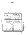
- Figure 1 is a schematic perspective view of a kneading machine according to the invention. It comprises a fixed tank 2 and two kneading implements 5 with fixed axis of rotation 5'.
- the kneading implements 5 define with their rotation respective theoretical cylinders of revolution 6, which, as may be seen in Figure 1 , are substantially tangential to one another.
- the tank 2 and the kneading implements 5 have dimensions such that the theoretical cylinders of revolution 6 occupy a substantial portion of free volume of the fixed tank 2.
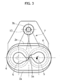
- the fixed tank 2 has a shape in plan view substantially like a figure eight, which reproduces the general contour of the set of the two kneading implements 5.
- the tank 2 has peripheral walls 2a that develop substantially adherent to the theoretical cylinders of revolution 6.
- the opposed peripheral walls 2a' that extend in the longitudinal direction of the tank 2 are respectively inclined by an angle P with respect to the vertical according to a path diverging upwards starting from the bottom of the tank so that they are substantially tangential to the theoretical cylinders of revolution 6 in their bottom region, and provided between these and the theoretical cylinders 6 is, instead, a space that increases as the distance from the bottom of the tank 2 increases.
- This particular configuration of the fixed tank 2 derives from the fact that the present applicant has noted that such a configuration favours a more effective mixing of the dough in so far as a substantial flow of recirculation of dough is further generated on planes transverse to the fixed tank 2 (represented generically by the plane of the sheet as viewed in Figure 4 ), a fact that increases the quality of the dough product.
- an inclination of the walls 2a' by an angle P comprised between approximately 0° and 15° generates an optimal action of recirculation and mixing of the dough.
- the kneading implements 5 are each formed by an arm 5a preferably having a polygonal cross section, which has a sharp edge, forming a cutting edge, in the area of the arm facing in the direction of advance and towards the outside of the circular path followed by the arm.
- said sharp edge is designated by 5b.
- the arm 5a extends for a substantially rectilinear part of its length and in a direction substantially parallel to the generatrix of the theoretical cylinder of revolution 6.
- the arm of the kneading implement of the type illustrated in Figures 1-9 can present a rectilinear portion that extends inclined with respect to the generatrix of the theoretical cylinder of revolution 6 by an angle not sensibly greater than 10°.
- Present on each tank 2 are an actuation means 7, designed to control rotation of the respective kneading implements 5.
- the actuation means comprise a respective pulley 7a, connected to each kneading implement 5 via a gearcase.
- the pulleys 7a are connected via respective drive belts to respective pulleys 7b carried by one and the same shaft 12 of a motor 13.
- the kneading implements 5 thus possess a synchronized movement of rotation.
- the kneading implements 5 are synchronised in such a way that the sharp edges 5b pass substantially simultaneously in the area of tangency of the respective theoretical cylinders 6, intercrossing in opposite directions of movement, on account of the concordant rotation of the two implements.
- peripheral walls 2a are substantially adherent to the theoretical cylinders of revolution 6, the kneading implements 5 perform an additional action of squeezing of the dough against the aforesaid peripheral walls 2a.
- the dough product is removed from the tank 2 manually or via means for picking it up of a conventional type.
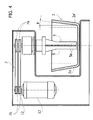
- the kneading machine can envisage a supporting structure 14 comprising a head part 14a, mounted on which are the aforesaid actuation means 7, the kneading implements 5, and the motor 13, which is translatable with respect to a base portion 14b on respective guides (not illustrated) provided therein, through the actuation of a hydraulic linear actuator 15.
- the head part 14a is in a lowered position such that the kneading implements 5 rotate within the tank 2, and in a subsequent step of discharging of the dough the head part 14a is raised in order to enable the fixed tank 2 to be moved via a carriage 16, on which it is mounted for carrying out discharging of the dough in a purposely designed and equipped area.
- FIG. 13 and 14 Illustrated in Figures 13 and 14 is a kneading machine according to the invention that has kneading implements 5 of the forklike type with inclined axis.
- the machine according to the invention has in this case a structure comprising a head part 14a that is rotatable with respect to the base part 14b in such a way that, in a discharge step, the head part 14a is rotated (in a clockwise direction as viewed Figure 13 ) for extracting the kneading implements 5 from the tank 2 so that the latter is free to be moved via the carriage 16 on which it is mounted.
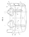
- Figures 6 to 11 and Figure 15 show further embodiments of the machine according to the invention in which the fixed tank 2 comprises a passage 3 that is made in a wall thereof and associated to which are means for adjustment of the width of the passage itself.
- the passage 3 is provided in an area corresponding to the peripheral wall 2a, on a longitudinal end of the tank 2.
- a mobile wall 4 which can be actuated according to a roller-shutter movement.
- Hydraulic control members 11 are designed to actuate the movement of the mobile wall 4, and control means (not illustrated) are provided for controlling operation thereof.
- a conduit 9 is provided for introduction of the ingredients that will form the dough.
- a conveying member 8 Present at one edge of the peripheral wall 2a delimiting the passage 3 is a conveying member 8.
- the conveying member 8 comprises a projecting distal end with a sharp edge 8b that extends tangentially to the theoretical cylinder of revolution adjacent thereto.
- the kneading implement 5 adjacent to the conveyor element 8 has a direction of rotation such that the sharp edge 5b of the kneading implement 5 is brought towards the conveying member 8 coming from the part the end 8b of the latter projects thereinto.
- the mobile wall 4 can be actuated via the aforesaid control means (not illustrated) so as to vary the width of the passage 3.
- the passage 3 constitutes an outlet for the dough so that the mobile wall 4 can be actuated so as to vary the flow of dough coming out of the machine.
- the mobile wall 4 is in a lowered position that closes the passage 3 completely.
- Ingredients that will be forming the dough are then introduced into the tank 2, through the conduit 9, the, and the two kneading implements 5 act simultaneously on the dough so as to exert a highly efficient kneading action.
- the kneading implements 5 of the type illustrated in Figures 1 to 9 exert on the dough a synergistic shearing action in the area of tangency of the respective theoretical cylinders of revolution.
- the mobile wall 4 is brought into a raised position so as to open the passage 3 at least partially and enable the kneaded dough to come out.
- the conveying means 8 is therefore able to speed up the discharge of the dough from the fixed tank 2.
- a further mode of operation of the kneading machine envisages, instead, that, during the step of working of the dough performed by the kneading implements 5, the mobile wall 4 is kept in a raised position so as to generate a continuous flow of kneaded product coming out of the machine through the passage 3.
- the mobile wall 4 can be actuated so as to adjust the outflow of the kneaded product and is likewise designed to determine the time of kneading to which the dough is coherently subjected.
- Figure 15 illustrates an embodiment of the machine according to the invention, in which the passage 3 is made on the bottom of the tank 2.
- the means for adjustment of the passage 3 are constituted by a hinged plug or hatch 4, which can turn in the plane of the figure and is set underneath the tank 2.
- the hatch 4 can be moved between a first position, in which it closes the passage 3, and a second position, in which the passage 3 is open and at the same time the hatch 4 acts so as to deflect the flow of dough coming out in an appropriate direction.
- a preferred embodiment of the invention envisages associating to the fixed tank 2 means that control the temperature and/or the pressure within the tank. It is in fact possible to envisage a fixed tank 2 having double walls, in which a space is provided for circulation of a diathermic fluid for controlling the temperature within the tank. Furthermore, there can be provided means for air-tight closing of the tank in order to enable any pressure to be set up therein. Since the kneading machine according to the invention is equipped with a fixed tank, the aforesaid means designed to control the environment of the dough within the tank can be easily prearranged on the structure of the tank itself, without this implying any particularly burdensome structural complication of the machine.
Landscapes
- Chemical & Material Sciences (AREA)
- Chemical Kinetics & Catalysis (AREA)
- Life Sciences & Earth Sciences (AREA)
- Engineering & Computer Science (AREA)
- Food Science & Technology (AREA)
- Manufacturing And Processing Devices For Dough (AREA)
- Mixers Of The Rotary Stirring Type (AREA)
Abstract
Described herein is a machine for the production of dough mixes, in particular dough mixes for foodstuffs, characterized in that it comprises a fixed tank (2) and at least two kneading implements (5) with fixed axis of rotation (5').
Description
- The present invention relates to a machine for the production of dough mixes, in particular dough mixes for foodstuffs.
- There are known in the technical field kneading machines for the production of dough in batches, of the type for example illustrated in the European patent application No.
EP-A-1676629 , filed in the name of the present applicant. The solution described in this application envisages a planetary kneading machine comprising: a tank; one or more kneading implements that can turn about the respective vertical axes, which are set at a distance from a central vertical shaft; a planetary structure for supporting the kneading implements, on which each kneading implement is mounted so that it can turn about its own axis, the planetary supporting structure being in turn mounted so that it can turn about the central shaft of the tank on a structure for supporting the machine; first means for controlling rotation of the planetary structure about the central shaft of the tank; and second means for controlling rotation of each kneading implement about its own axis. Even though kneading machines of this type are able to exert a highly efficient kneading action, they present the disadvantage of having a complex and extremely delicate structure. In fact, the planetary supporting structure that is mounted so that it can turn about the central shaft of the tank is subject to considerable stress during the kneading action and is liable to failure above all in points corresponding to the members for support and transmission of the motion. - Moreover known in the art are kneading machines for foodstuff products of the type described, for example, in the European patent application No.
EP-A-1707052 , filed in the name of the present applicant. This document describes a kneading machine comprising a substantially cylindrical tank that turns about an axis thereof, and at least one kneading implement that can turn within the tank, about an axis substantially parallel to the axis of the tank. A solution of this type has a structure that is more robust than that of the solution described previously, but is afflicted, however, by the problems inherent in the fact of producing a rotary tank to which it is extremely complicated to associate means for controlling the temperature that envisage a circulation of diathermic fluid about the walls of the tank itself, or else means for controlling the pressure that comprise means of air-tight sealing. - The present invention proposes a solution to the problems and disadvantages presented by the machines according to the known art by providing a machine for the production of dough mixes, in particular of dough mixes for foodstuffs, presenting the characteristics of
Claim 1. - Further characteristics and advantages will emerge clearly from the attached plate of drawings, which are provided purely by way of non-limiting example and in which:
-
Figure 1 is a schematic perspective view of the machine according to the invention; -
Figure 2 is a front cross-sectional view of an embodiment of the machine according to the invention; -
Figure 3 is a top plan view of the machine ofFigure 2 ; -
Figure 4 is a cross-sectional side view of the machine ofFigure 3 ; -
Figure 5 is a cross-sectional side view of a further embodiment of the machine according to the invention; -
Figure 6 is a schematic perspective view of a further embodiment of the machine according to the invention; -
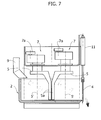
Figure 7 is a front cross-sectional view of a further embodiment of the machine according to the invention; -
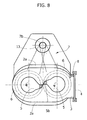
Figure 8 is a top plan view of the machine ofFigure 7 ; -
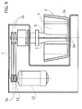
Figure 9 is a cross-sectional side view of the machine illustrated inFigure 7 ; -
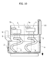
Figure 10 is a front cross-sectional view of a further embodiment of the machine according to the invention; -
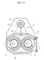
Figure 11 is a top plan view of the machine ofFigure 10 ; -
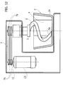
Figure 12 is a cross-sectional side view of the machine ofFigure 10 ; -
Figure 13 is a cross-sectional side view of a further embodiment of the machine according to the invention; -
Figure 14 is a front view of the machine ofFigure 13 ; -
Figure 15 is a front cross-sectional view of a further embodiment of the machine according to the invention; -
Figure 16 is a schematic perspective view of a further embodiment of the machine according to the invention; and -
Figure 17 is a plan view of the machine according to the embodiment ofFigure 16 . -
Figure 1 is a schematic perspective view of a kneading machine according to the invention. It comprises afixed tank 2 and twokneading implements 5 with fixed axis of rotation 5'. Thekneading implements 5 define with their rotation respective theoretical cylinders ofrevolution 6, which, as may be seen inFigure 1 , are substantially tangential to one another. Thetank 2 and thekneading implements 5 have dimensions such that the theoretical cylinders ofrevolution 6 occupy a substantial portion of free volume of thefixed tank 2. In fact, since thetank 2 is fixed and thekneading implements 5 have respective axes of rotation 5' that are also fixed, thekneading implements 5 are prearranged for acting during their rotation on all the dough contained within thefixed tank 2. InFigures 16 and17 , thefixed tank 2 has a shape in plan view substantially like a figure eight, which reproduces the general contour of the set of the twokneading implements 5. - In particular, the
tank 2 hasperipheral walls 2a that develop substantially adherent to the theoretical cylinders ofrevolution 6. As may be seen inFigure 4 , the opposedperipheral walls 2a' that extend in the longitudinal direction of thetank 2 are respectively inclined by an angle P with respect to the vertical according to a path diverging upwards starting from the bottom of the tank so that they are substantially tangential to the theoretical cylinders ofrevolution 6 in their bottom region, and provided between these and thetheoretical cylinders 6 is, instead, a space that increases as the distance from the bottom of thetank 2 increases. This particular configuration of thefixed tank 2 derives from the fact that the present applicant has noted that such a configuration favours a more effective mixing of the dough in so far as a substantial flow of recirculation of dough is further generated on planes transverse to the fixed tank 2 (represented generically by the plane of the sheet as viewed inFigure 4 ), a fact that increases the quality of the dough product. In particular, it is found that an inclination of thewalls 2a' by an angle P comprised between approximately 0° and 15° generates an optimal action of recirculation and mixing of the dough. - In general, it is noted that the provision of theoretical cylinders of
revolution 6 that as a whole occupy a volume equal to a value comprised between 40% and 80% of the free volume of thefixed tank 2 is a machine configuration that ensures very high performance of the kneading action of the machine according to the invention. - In the embodiments illustrated in
Figures 1-9 , thekneading implements 5 are each formed by anarm 5a preferably having a polygonal cross section, which has a sharp edge, forming a cutting edge, in the area of the arm facing in the direction of advance and towards the outside of the circular path followed by the arm. In the example of embodiment described herein, said sharp edge is designated by 5b. - The
arm 5a extends for a substantially rectilinear part of its length and in a direction substantially parallel to the generatrix of the theoretical cylinder ofrevolution 6. Alternatively, the arm of the kneading implement of the type illustrated inFigures 1-9 can present a rectilinear portion that extends inclined with respect to the generatrix of the theoretical cylinder ofrevolution 6 by an angle not sensibly greater than 10°. Present on eachtank 2 are an actuation means 7, designed to control rotation of therespective kneading implements 5. As illustrated inFigures 2 and4 , the actuation means comprise arespective pulley 7a, connected to each kneading implement 5 via a gearcase. Thepulleys 7a are connected via respective drive belts torespective pulleys 7b carried by one and thesame shaft 12 of amotor 13. Thekneading implements 5 thus possess a synchronized movement of rotation. Preferably, thekneading implements 5 are synchronised in such a way that thesharp edges 5b pass substantially simultaneously in the area of tangency of the respectivetheoretical cylinders 6, intercrossing in opposite directions of movement, on account of the concordant rotation of the two implements. In this way, at the point of tangency of the two theoretical cylinders ofrevolution 6 the two kneading implements 5 co-operate so as to exert a shearing action on the dough, which improves the quality of the kneaded product. - Furthermore, since the
peripheral walls 2a are substantially adherent to the theoretical cylinders ofrevolution 6, the kneading implements 5 perform an additional action of squeezing of the dough against the aforesaidperipheral walls 2a. - In the embodiment illustrated in
Figures 2-4 , the dough product is removed from thetank 2 manually or via means for picking it up of a conventional type. - Alternatively, as illustrated in
Figure 5 , the kneading machine according to the invention can envisage a supportingstructure 14 comprising ahead part 14a, mounted on which are the aforesaid actuation means 7, thekneading implements 5, and themotor 13, which is translatable with respect to abase portion 14b on respective guides (not illustrated) provided therein, through the actuation of a hydrauliclinear actuator 15. In this embodiment of the kneading machine according to the invention, during the step of working of the dough thehead part 14a is in a lowered position such that the kneading implements 5 rotate within thetank 2, and in a subsequent step of discharging of the dough thehead part 14a is raised in order to enable thefixed tank 2 to be moved via acarriage 16, on which it is mounted for carrying out discharging of the dough in a purposely designed and equipped area. - Illustrated in
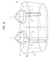
Figures 13 and14 is a kneading machine according to the invention that has kneading implements 5 of the forklike type with inclined axis. The machine according to the invention has in this case a structure comprising ahead part 14a that is rotatable with respect to thebase part 14b in such a way that, in a discharge step, thehead part 14a is rotated (in a clockwise direction as viewedFigure 13 ) for extracting thekneading implements 5 from thetank 2 so that the latter is free to be moved via thecarriage 16 on which it is mounted. -
Figures 6 to 11 andFigure 15 show further embodiments of the machine according to the invention in which thefixed tank 2 comprises apassage 3 that is made in a wall thereof and associated to which are means for adjustment of the width of the passage itself. - In particular in
Figures 6 to 11 , thepassage 3 is provided in an area corresponding to theperipheral wall 2a, on a longitudinal end of thetank 2. Provided in a position corresponding to thepassage 3 is amobile wall 4, which can be actuated according to a roller-shutter movement.Hydraulic control members 11 are designed to actuate the movement of themobile wall 4, and control means (not illustrated) are provided for controlling operation thereof. Furthermore, as may be seen inFigures 7 and10 , aconduit 9 is provided for introduction of the ingredients that will form the dough. - Present at one edge of the
peripheral wall 2a delimiting thepassage 3 is a conveyingmember 8. The conveyingmember 8 comprises a projecting distal end with a sharp edge 8b that extends tangentially to the theoretical cylinder of revolution adjacent thereto. In operation, the kneading implement 5 adjacent to theconveyor element 8 has a direction of rotation such that thesharp edge 5b of thekneading implement 5 is brought towards the conveyingmember 8 coming from the part the end 8b of the latter projects thereinto. - The
mobile wall 4 can be actuated via the aforesaid control means (not illustrated) so as to vary the width of thepassage 3. Thepassage 3 constitutes an outlet for the dough so that themobile wall 4 can be actuated so as to vary the flow of dough coming out of the machine. - According to a preferred mode of operation, during working of the dough by the kneading implements 5, the
mobile wall 4 is in a lowered position that closes thepassage 3 completely. Ingredients that will be forming the dough are then introduced into thetank 2, through theconduit 9, the, and the two kneadingimplements 5 act simultaneously on the dough so as to exert a highly efficient kneading action. As already mentioned previously, the kneading implements 5 of the type illustrated inFigures 1 to 9 exert on the dough a synergistic shearing action in the area of tangency of the respective theoretical cylinders of revolution. Once the step of working of the dough is completed, themobile wall 4 is brought into a raised position so as to open thepassage 3 at least partially and enable the kneaded dough to come out. The conveyingmember 8, provided in the embodiment described herein, acts so as to intercept and free the dough from the kneading implement 5 adjacent thereto, to send it out of thetank 2. The conveying means 8 is therefore able to speed up the discharge of the dough from the fixedtank 2. - A further mode of operation of the kneading machine envisages, instead, that, during the step of working of the dough performed by the kneading implements 5, the
mobile wall 4 is kept in a raised position so as to generate a continuous flow of kneaded product coming out of the machine through thepassage 3. Themobile wall 4 can be actuated so as to adjust the outflow of the kneaded product and is likewise designed to determine the time of kneading to which the dough is coherently subjected. -
Figure 15 illustrates an embodiment of the machine according to the invention, in which thepassage 3 is made on the bottom of thetank 2. In this case, the means for adjustment of thepassage 3 are constituted by a hinged plug orhatch 4, which can turn in the plane of the figure and is set underneath thetank 2. Thehatch 4 can be moved between a first position, in which it closes thepassage 3, and a second position, in which thepassage 3 is open and at the same time thehatch 4 acts so as to deflect the flow of dough coming out in an appropriate direction. In the operation of the embodiment illustrated inFigure 15 , it is preferable to provide a control of thehatch 4, in which, during working of the dough within thetank 2, thehatch 4 is in the aforesaid first position and subsequently is activated to move into the second position in order to cause the dough to come out by the force of gravity. - A preferred embodiment of the invention envisages associating to the fixed
tank 2 means that control the temperature and/or the pressure within the tank. It is in fact possible to envisage afixed tank 2 having double walls, in which a space is provided for circulation of a diathermic fluid for controlling the temperature within the tank. Furthermore, there can be provided means for air-tight closing of the tank in order to enable any pressure to be set up therein. Since the kneading machine according to the invention is equipped with a fixed tank, the aforesaid means designed to control the environment of the dough within the tank can be easily prearranged on the structure of the tank itself, without this implying any particularly burdensome structural complication of the machine. - Of course the details of construction and the embodiments of the invention may vary widely with respect to what is described and illustrated herein, without thereby departing from the scope of the present invention, as defined in the ensuing claims.
Claims (21)
- A machine for the production of dough mixes, in particular dough mixes for foodstuffs, characterized in that it comprises a fixed tank (2) and at least two kneading implements (5) with fixed axis of rotation (5').
- The machine according to Claim 1, characterized in that said at least two kneading implements define respective theoretical cylinders of revolution (6) that occupy as a whole a volume equal to a value comprised between 40% and 80% of the free volume of said fixed tank.
- The machine according to Claim 1, characterized in that said fixed tank (2) has at least one peripheral wall (2a') inclined with respect to the vertical according to a path diverging upwards starting from the bottom of the tank.
- The machine according to Claim 3, characterized in that said peripheral wall (2a') is inclined with respect to the vertical by an angle P comprised between approximately 0° and 15°.
- The machine according to Claim 1, characterized in that said fixed tank comprises a passage made in a wall thereof, associated to which are means for adjustment of said passage.
- The machine according to Claim 5, characterized in that said passage is made in a peripheral wall of said fixed tank (2).
- The machine according to Claim 5, characterized in that said passage is made in a bottom wall of said fixed tank (2).
- The machine according to Claim 1, characterized in that said at least two kneading implements (5) are prearranged to skim one or more peripheral walls of said fixed tank (2) so as to create an action of squeezing of the dough against said one or more peripheral walls.
- The machine according to Claim 2, characterized in that said at least two kneading implements (5), for a part of their length are substantially rectilinear and extend in a direction substantially parallel or inclined with respect to a generatrix of said theoretical cylinders of revolution (6) by an angle not sensibly greater than 10°.
- The machine according to Claim 1, characterized in that said at least two kneading implements (5) are spiral kneading implements.
- The machine according to Claim 1, characterized in that said at least two kneading implements (5) are forklike implements with inclined axis.
- The machine according to Claim 1, characterized in that said two kneading implements (5) are of types different from one another.
- The machine according to Claim 5, characterized in that said fixed tank (2) has a shape in plan view included in the group comprising rectangular and conical shapes or is in the form of a figure eight.
- The machine according to Claim 1, characterized in that said fixed tank (2) is associated to means for introducing the ingredients of the dough (9).
- The machine according to Claim 5, characterized in that said means for adjustment of said passage comprise a mobile portion of wall of said fixed tank.
- The machine according to Claim 6 and 15, characterized in that said mobile portion of wall can be actuated according to a roller-shutter movement.
- The machine according to Claim 6, characterized in that said fixed tank (2) comprises conveying means (8) designed to direct the dough through said passage.
- The machine according to Claim 17, characterized in that said conveying means comprise a fixed member set in the vicinity of said passage in such a way as to intercept the dough worked by said at least two kneading implements (5) and direct it outside of said fixed tank (2).
- The machine according to Claim 1, characterized in that said fixed tank (2) has double walls, in which a space is provided for circulation of a fluid for control of the temperature within the chamber.
- The machine according to Claim 1, characterized in that said fixed tank (2) is hermetically closed in order to be able to work in conditions of modified atmosphere.
- The machine according to Claim 7, characterized in that said means for adjustment of said passage comprise a hinged plug or hatch.
Priority Applications (5)
| Application Number | Priority Date | Filing Date | Title |
|---|---|---|---|
| EP07425148A EP1969943A1 (en) | 2007-03-16 | 2007-03-16 | Kneading machine for food products |
| AT08152426T ATE525909T1 (en) | 2007-03-16 | 2008-03-07 | KNEADING MACHINE FOR FOOD |
| EP08152426A EP1969944B1 (en) | 2007-03-16 | 2008-03-07 | Kneading machine for food products |
| EP11172963A EP2374356B1 (en) | 2007-03-16 | 2008-03-07 | Kneading machine for food products |
| US12/048,755 US8322912B2 (en) | 2007-03-16 | 2008-03-14 | Kneading machine for food products |
Applications Claiming Priority (1)
| Application Number | Priority Date | Filing Date | Title |
|---|---|---|---|
| EP07425148A EP1969943A1 (en) | 2007-03-16 | 2007-03-16 | Kneading machine for food products |
Publications (1)
| Publication Number | Publication Date |
|---|---|
| EP1969943A1 true EP1969943A1 (en) | 2008-09-17 |
Family
ID=38292643
Family Applications (3)
| Application Number | Title | Priority Date | Filing Date |
|---|---|---|---|
| EP07425148A Withdrawn EP1969943A1 (en) | 2007-03-16 | 2007-03-16 | Kneading machine for food products |
| EP11172963A Active EP2374356B1 (en) | 2007-03-16 | 2008-03-07 | Kneading machine for food products |
| EP08152426A Not-in-force EP1969944B1 (en) | 2007-03-16 | 2008-03-07 | Kneading machine for food products |
Family Applications After (2)
| Application Number | Title | Priority Date | Filing Date |
|---|---|---|---|
| EP11172963A Active EP2374356B1 (en) | 2007-03-16 | 2008-03-07 | Kneading machine for food products |
| EP08152426A Not-in-force EP1969944B1 (en) | 2007-03-16 | 2008-03-07 | Kneading machine for food products |
Country Status (3)
| Country | Link |
|---|---|
| US (1) | US8322912B2 (en) |
| EP (3) | EP1969943A1 (en) |
| AT (1) | ATE525909T1 (en) |
Cited By (1)
| Publication number | Priority date | Publication date | Assignee | Title |
|---|---|---|---|---|
| CN111887271A (en) * | 2020-08-13 | 2020-11-06 | 绍兴三盈食品有限责任公司 | Automatic dough mixing machine |
Families Citing this family (3)
| Publication number | Priority date | Publication date | Assignee | Title |
|---|---|---|---|---|
| CN109203272A (en) * | 2018-08-20 | 2019-01-15 | 广州唐太环保科技有限公司 | A kind of polyvinyl chloride mixing apparatus |
| CN113907099B (en) * | 2021-11-03 | 2022-09-20 | 河北金田麦国际食品有限公司 | Vacuum extrusion tilter for dough |
| CN114081048B (en) * | 2021-11-24 | 2022-07-26 | 江门市大晖科技有限公司 | Automatic dough kneading machine and dough kneading method |
Citations (5)
| Publication number | Priority date | Publication date | Assignee | Title |
|---|---|---|---|---|
| FR7799E (en) * | 1907-02-13 | 1907-10-11 | Ch Lumpp & Cie Soc | Mechanical mixer |
| FR382856A (en) * | 1907-10-14 | 1908-02-18 | Louis Teillon | Mechanical mixer |
| FR9804E (en) * | 1907-10-14 | 1909-02-02 | Louis Teillon | Mechanical mixer |
| CH239203A (en) * | 1943-05-25 | 1945-09-30 | V H Rogier Nerincx Richter Nv | Dough kneading and mixing machine. |
| EP1342501A2 (en) * | 2002-03-05 | 2003-09-10 | SANCASSIANO S.p.A. | Kneading machine for food doughs, particularly for bakery products |
Family Cites Families (10)
| Publication number | Priority date | Publication date | Assignee | Title |
|---|---|---|---|---|
| DE1037089B (en) * | 1956-11-09 | 1958-08-21 | Siemens Elektrogeraete Gmbh | Kitchen machine |
| DE2434330A1 (en) * | 1974-07-17 | 1976-01-29 | Stephan & Soehne | DOUGH MIXING AND MIXING MACHINE |
| SE7901204L (en) * | 1978-02-15 | 1979-10-08 | Baker Perkins Holdings Ltd | KIT AND APPLIANCE FOR TREATMENT OF YOU |
| US4277181A (en) * | 1979-04-26 | 1981-07-07 | Sunbeam Corporation | Food mixer |
| ES8105556A1 (en) * | 1979-10-03 | 1981-06-16 | Halley Louis Erne | Weigher for pasty materials such as bread dough, and kneader-mixer-weigher equipped with such a weigher. |
| GB8817260D0 (en) * | 1988-07-20 | 1988-08-24 | Kenwood Ltd | Breadmaking machines |
| JPH04346742A (en) * | 1991-05-24 | 1992-12-02 | Tokyo Electric Co Ltd | Stirring cooker |
| ITTO20040892A1 (en) | 2004-12-21 | 2005-03-21 | Sancassiano Spa | PLANETARY MIXING MACHINE FOR FOODSTUFFS |
| ITTO20050199A1 (en) | 2005-03-29 | 2006-09-30 | Sancassiano Spa | MIXER MIXER FOR MIXER FOR FOODSTUFFS |
| US7866877B2 (en) * | 2006-12-22 | 2011-01-11 | Cmc America Corporation | Method and apparatus for mixing dough |
-
2007
- 2007-03-16 EP EP07425148A patent/EP1969943A1/en not_active Withdrawn
-
2008
- 2008-03-07 EP EP11172963A patent/EP2374356B1/en active Active
- 2008-03-07 AT AT08152426T patent/ATE525909T1/en not_active IP Right Cessation
- 2008-03-07 EP EP08152426A patent/EP1969944B1/en not_active Not-in-force
- 2008-03-14 US US12/048,755 patent/US8322912B2/en active Active
Patent Citations (6)
| Publication number | Priority date | Publication date | Assignee | Title |
|---|---|---|---|---|
| FR7799E (en) * | 1907-02-13 | 1907-10-11 | Ch Lumpp & Cie Soc | Mechanical mixer |
| FR382856A (en) * | 1907-10-14 | 1908-02-18 | Louis Teillon | Mechanical mixer |
| FR9804E (en) * | 1907-10-14 | 1909-02-02 | Louis Teillon | Mechanical mixer |
| CH239203A (en) * | 1943-05-25 | 1945-09-30 | V H Rogier Nerincx Richter Nv | Dough kneading and mixing machine. |
| EP1342501A2 (en) * | 2002-03-05 | 2003-09-10 | SANCASSIANO S.p.A. | Kneading machine for food doughs, particularly for bakery products |
| EP1550499A2 (en) * | 2002-03-05 | 2005-07-06 | SANCASSIANO S.p.A. | Kneading machine for food doughs, particularly for bakery products |
Cited By (2)
| Publication number | Priority date | Publication date | Assignee | Title |
|---|---|---|---|---|
| CN111887271A (en) * | 2020-08-13 | 2020-11-06 | 绍兴三盈食品有限责任公司 | Automatic dough mixing machine |
| CN111887271B (en) * | 2020-08-13 | 2021-11-23 | 绍兴三盈食品有限责任公司 | Automatic dough mixing machine |
Also Published As
| Publication number | Publication date |
|---|---|
| US8322912B2 (en) | 2012-12-04 |
| EP1969944B1 (en) | 2011-09-28 |
| EP2374356B1 (en) | 2012-11-28 |
| US20080225633A1 (en) | 2008-09-18 |
| EP1969944A3 (en) | 2009-08-19 |
| EP1969944A2 (en) | 2008-09-17 |
| ATE525909T1 (en) | 2011-10-15 |
| EP2374356A1 (en) | 2011-10-12 |
Similar Documents
| Publication | Publication Date | Title |
|---|---|---|
| EP1969943A1 (en) | Kneading machine for food products | |
| JP4274569B2 (en) | Method and apparatus for extruding food material | |
| US9022768B2 (en) | Variable diameter, variable pitch auger with material scraper and breaker bar | |
| EP2394734B1 (en) | Apparatus for the production of spun mozzarella or other soft dairy product, starting with frozen raw material | |
| CN110947328A (en) | Mixer for food processing | |
| JP2010088312A (en) | Steaming kneader | |
| EP1991463B1 (en) | Filling apparatus for containers which are open at the top | |
| EP1969942A1 (en) | Kneading machine for producing a sequence of dough batches | |
| CN204054140U (en) | A kind of Pou Feng mechanism of bread producing machine and the bread producing machine of application thereof | |
| EP1527688B1 (en) | Horizontal kneading machine for edible dough, particularly for oven-baked products | |
| EP1935592A1 (en) | Device for cutting food with ultrasound and ultrasonically activated cutting tools | |
| US20170112147A1 (en) | Automatic table-top machine for kneading and extruding pasta | |
| US20160302467A1 (en) | Device and method for forming food products | |
| DK2327296T3 (en) | Method for adjusting the power range of a buttering machine to a cream flow volume | |
| DE102012105712A1 (en) | Food dispenser device and method for portioning and dispensing flowable foodstuffs | |
| KR101817313B1 (en) | Apparatus for injecting cream | |
| EP2550864A2 (en) | Bread dough dividing machine | |
| KR101677687B1 (en) | Doughnut Forming Apparatus | |
| CN215684502U (en) | Auger dough kneading device | |
| CN211366276U (en) | Quick feeding device of warm chartered plane | |
| EP2904904B1 (en) | Kneading machine for a food dough | |
| JP6041365B2 (en) | Food dough splitting equipment | |
| CN110720479A (en) | Double-stirring device | |
| JP2022020022A (en) | Method and apparatus for making wrapped food | |
| US20030047085A1 (en) | Apportioning and kneading device for dough |
Legal Events
| Date | Code | Title | Description |
|---|---|---|---|
| PUAI | Public reference made under article 153(3) epc to a published international application that has entered the european phase |
Free format text: ORIGINAL CODE: 0009012 |
|
| AK | Designated contracting states |
Kind code of ref document: A1 Designated state(s): AT BE BG CH CY CZ DE DK EE ES FI FR GB GR HU IE IS IT LI LT LU LV MC MT NL PL PT RO SE SI SK TR |
|
| AX | Request for extension of the european patent |
Extension state: AL BA HR MK RS |
|
| AKX | Designation fees paid | ||
| REG | Reference to a national code |
Ref country code: DE Ref legal event code: 8566 |
|
| STAA | Information on the status of an ep patent application or granted ep patent |
Free format text: STATUS: THE APPLICATION IS DEEMED TO BE WITHDRAWN |
|
| 18D | Application deemed to be withdrawn |
Effective date: 20090318 |