EP1969418B1 - Schraubenlose magnetische brille - Google Patents
Schraubenlose magnetische brille Download PDFInfo
- Publication number
- EP1969418B1 EP1969418B1 EP06840234.6A EP06840234A EP1969418B1 EP 1969418 B1 EP1969418 B1 EP 1969418B1 EP 06840234 A EP06840234 A EP 06840234A EP 1969418 B1 EP1969418 B1 EP 1969418B1
- Authority
- EP
- European Patent Office
- Prior art keywords
- magnets
- members
- magnetic
- magnetic connector
- eyewear
- Prior art date
- Legal status (The legal status is an assumption and is not a legal conclusion. Google has not performed a legal analysis and makes no representation as to the accuracy of the status listed.)
- Active
Links
- 230000007246 mechanism Effects 0.000 claims description 19
- 239000011241 protective layer Substances 0.000 claims description 6
- 230000001846 repelling effect Effects 0.000 claims 1
- 239000000463 material Substances 0.000 description 16
- 229920001971 elastomer Polymers 0.000 description 6
- 229910052751 metal Inorganic materials 0.000 description 6
- 239000002184 metal Substances 0.000 description 6
- 239000004033 plastic Substances 0.000 description 6
- 229920003023 plastic Polymers 0.000 description 6
- 239000005060 rubber Substances 0.000 description 6
- 230000000295 complement effect Effects 0.000 description 5
- 239000004593 Epoxy Substances 0.000 description 4
- 230000008878 coupling Effects 0.000 description 4
- 238000010168 coupling process Methods 0.000 description 4
- 238000005859 coupling reaction Methods 0.000 description 4
- 239000003292 glue Substances 0.000 description 4
- RTAQQCXQSZGOHL-UHFFFAOYSA-N Titanium Chemical compound [Ti] RTAQQCXQSZGOHL-UHFFFAOYSA-N 0.000 description 3
- 238000005452 bending Methods 0.000 description 3
- 230000000694 effects Effects 0.000 description 3
- 238000010438 heat treatment Methods 0.000 description 3
- 230000008439 repair process Effects 0.000 description 3
- 239000010936 titanium Substances 0.000 description 3
- 229910052719 titanium Inorganic materials 0.000 description 3
- 238000011282 treatment Methods 0.000 description 3
- 206010061619 Deformity Diseases 0.000 description 2
- 229910052782 aluminium Inorganic materials 0.000 description 2
- XAGFODPZIPBFFR-UHFFFAOYSA-N aluminium Chemical compound [Al] XAGFODPZIPBFFR-UHFFFAOYSA-N 0.000 description 2
- 230000008901 benefit Effects 0.000 description 2
- 230000003203 everyday effect Effects 0.000 description 2
- 239000010410 layer Substances 0.000 description 2
- 239000004417 polycarbonate Substances 0.000 description 2
- 229920000515 polycarbonate Polymers 0.000 description 2
- 230000001681 protective effect Effects 0.000 description 2
- 229910001220 stainless steel Inorganic materials 0.000 description 2
- 239000010935 stainless steel Substances 0.000 description 2
- 229910001040 Beta-titanium Inorganic materials 0.000 description 1
- CWYNVVGOOAEACU-UHFFFAOYSA-N Fe2+ Chemical compound [Fe+2] CWYNVVGOOAEACU-UHFFFAOYSA-N 0.000 description 1
- 229910052779 Neodymium Inorganic materials 0.000 description 1
- 239000004677 Nylon Substances 0.000 description 1
- 238000004026 adhesive bonding Methods 0.000 description 1
- 230000008859 change Effects 0.000 description 1
- KPLQYGBQNPPQGA-UHFFFAOYSA-N cobalt samarium Chemical compound [Co].[Sm] KPLQYGBQNPPQGA-UHFFFAOYSA-N 0.000 description 1
- 239000003086 colorant Substances 0.000 description 1
- 230000007797 corrosion Effects 0.000 description 1
- 238000005260 corrosion Methods 0.000 description 1
- 238000000354 decomposition reaction Methods 0.000 description 1
- 230000001627 detrimental effect Effects 0.000 description 1
- 238000006073 displacement reaction Methods 0.000 description 1
- 239000004744 fabric Substances 0.000 description 1
- 230000004907 flux Effects 0.000 description 1
- -1 for examples Substances 0.000 description 1
- 230000000774 hypoallergenic effect Effects 0.000 description 1
- 230000001939 inductive effect Effects 0.000 description 1
- 238000003780 insertion Methods 0.000 description 1
- 230000037431 insertion Effects 0.000 description 1
- 238000004519 manufacturing process Methods 0.000 description 1
- 210000001595 mastoid Anatomy 0.000 description 1
- 150000002739 metals Chemical class 0.000 description 1
- 238000000034 method Methods 0.000 description 1
- QEFYFXOXNSNQGX-UHFFFAOYSA-N neodymium atom Chemical compound [Nd] QEFYFXOXNSNQGX-UHFFFAOYSA-N 0.000 description 1
- 229920001778 nylon Polymers 0.000 description 1
- 239000003921 oil Substances 0.000 description 1
- 239000011368 organic material Substances 0.000 description 1
- 230000002093 peripheral effect Effects 0.000 description 1
- 229920000642 polymer Polymers 0.000 description 1
- 229920001296 polysiloxane Polymers 0.000 description 1
- 230000000284 resting effect Effects 0.000 description 1
- 238000009420 retrofitting Methods 0.000 description 1
- 229910000938 samarium–cobalt magnet Inorganic materials 0.000 description 1
- 238000000926 separation method Methods 0.000 description 1
- 238000005476 soldering Methods 0.000 description 1
- 125000000391 vinyl group Chemical group [H]C([*])=C([H])[H] 0.000 description 1
- 229920002554 vinyl polymer Polymers 0.000 description 1
- 238000003466 welding Methods 0.000 description 1
Images


Classifications
-
- G—PHYSICS
- G02—OPTICS
- G02C—SPECTACLES; SUNGLASSES OR GOGGLES INSOFAR AS THEY HAVE THE SAME FEATURES AS SPECTACLES; CONTACT LENSES
- G02C5/00—Constructions of non-optical parts
- G02C5/22—Hinges
- G02C5/2209—Pivot bearings and hinge bolts other than screws
-
- G—PHYSICS
- G02—OPTICS
- G02C—SPECTACLES; SUNGLASSES OR GOGGLES INSOFAR AS THEY HAVE THE SAME FEATURES AS SPECTACLES; CONTACT LENSES
- G02C2200/00—Generic mechanical aspects applicable to one or more of the groups G02C1/00 - G02C5/00 and G02C9/00 - G02C13/00 and their subgroups
- G02C2200/02—Magnetic means
-
- G—PHYSICS
- G02—OPTICS
- G02C—SPECTACLES; SUNGLASSES OR GOGGLES INSOFAR AS THEY HAVE THE SAME FEATURES AS SPECTACLES; CONTACT LENSES
- G02C2200/00—Generic mechanical aspects applicable to one or more of the groups G02C1/00 - G02C5/00 and G02C9/00 - G02C13/00 and their subgroups
- G02C2200/08—Modular frames, easily exchangeable frame parts and lenses
Definitions
- the invention relates to a connector for use in eyewear, and particularly to a magnetic connector that can be used at connection points of eyewear.
- WO 2004/066019 discloses a frame for eyeglasses comprising a lens supporting structure and two temples each connected to the supporting structure by a hinge device.
- the hinge device comprises a first magnetic element applied integral with the lens supporting structure and a second magnet element applied integral with the temples. The magnetic elements are engaged with each other to allow relative movement between the temples and the lens supporting structure.
- US 6,217,170 discloses a magnetic coupling system for securing a temple to an eyeglass hinge.
- the coupling system includes a pivotal flange containing a coupling magnet on the rear end of the eyeglass hinge.
- the temple includes two magnets secured in a pair of opposed pivotal flanges for respective magnetic coupling to the magnet of the pivotal flange.
- US 3,422,449 discloses an eyeglass comprising a lens frame having an elongated permanent magnet secured at each outer end and further comprising two temples having a corresponding elongated permanent magnet.
- the magnets on the temple are magnetically held against the magnets on the lens frame providing pivotal movement of the temples relative to the lens.
- US 5,988,811 discloses a nose pad for spectacles comprising two bodies for contact with the nose, each body housing a permanent magnet.
- the magnets form attraction toward each other to prevent downward displacement of the spectacles along the nose.
- JP 10284317 discloses a magnet disposed in a concavity disposed in a connector for a member, and a magnet disposed in a concavity disposed in a connector for another member. The magnets mutually bond together and the two members are connected so as to be able to turn in relation to one another.
- JP 2004109841 discloses a pivotal connector between two members of an eyewear, including magnets which are press-fitted in the respective housings.
- EP 0971255 discloses an eyeglass frame including a pair of temples having a joint connected to the rim of the frame and a mechanism for enabling pivotal movement of the lenses in the frame.
- the present invention meets this need by providing a magnetic connector for use at connection points between members to magnetically connect members together, as defined by independent claim 1.
- the magnetic connector comprises first and second magnets, each positioned in or on first and second members, respectively.
- the magnets have substantially opposite polarities and are positioned substantially parallel to each other in a plane. Magnets rotate about an axis. When the magnets are positioned in sufficient proximity to each other to create a magnetic field of attraction, members are thereby substantially connected.
- magnets are in either a horizontal or vertical plane. In a preferred example, there is a means of limiting rotation to prevent magnets from rotating 360° about the axis.
- the invention is a magnetic connector comprising first and second magnets of substantially the same polarity, as defined by independent claim 8.
- One magnet is positioned in or on a first member and the other magnet is positioned in or on a second member. Magnets are positioned substantially parallel to each other in a plane and rotate about an axis.
- the connector further comprises a lock and key configured to engage each other.
- the lock is located on one of the members and the key is located on the other member. When the lock and key are engaged, and magnets are positioned in proximity to each other sufficient to create a field of magnetic repulsion, members are pushed away from each other and a tension is created that secures the engagement between the lock and key, thereby securing the connection of first and second members.
- a preferred example of the present invention is a pair of eyeglasses comprising first and second members and the magnetic connector that connects members at a connection point, as defined in either of claims 1 or 8.
- conventional eyewear is retrofitted with a magnetic hinge adapter that converts and replaces conventional connectors such as miniature screw and hinge mechanisms to a magnetic connector.
- the magnetic hinge adapter comprises at least one adapter piece comprising a magnetic surface and at least one platform having a hole therein.
- the adapter piece is configured to integrate with the screw hinge to secure the adapter piece to the screw hinge.
- the hole in the platform of the adapter piece substantially aligns with a hole in a platform of the screw hinge. When aligned, the holes are capable of receiving a securing means to secure the magnetic adapter piece to the screw hinge.
- the magnetic hinge adapter further comprises a second adapter piece. Magnetic surfaces of adapter pieces are magnetically attracted so that first and second adapter pieces are a connection point between two members of eyewear, thereby providing a flexible point of connection.
- the present invention provides a magnetic connector 1 for use at connection points in eyewear 10.
- Magnetic connector 1 minimizes damage to eyewear 10 when a component or member 2 of the eyewear is bent or tensioned by causing adjacent members 2 to easily detach when magnets 3 are not in substantial proximity to each other such as when angle ⁇ between members is greater than about 110°.
- magnetic connector 1 provides fashion eyewear that has interchangeable members, for example, members having different prints, colors, or designs to provide eyewear having a variety of aesthetic appearances.
- magnetic connector 1 provides an easy way to repair eyewear, such as by replacing a member, for example when member is damaged.
- Magnetic connector 1 eliminates the need for conventional connectors such as screw hinges and enables members 2 of eyewear 10 to be substantially connected to each other by the magnetic force between magnets 3 comprising the magnetic connector 1.
- magnets 3 comprising magnetic connector 1 keep connected members 2 substantially aligned.
- pairs of magnets 3 that are substantially rectangular are substantially self-righting and generally return to a substantially parallel planar arrangement even when magnets 3 are forced apart by pressure on one of magnets 3.
- Magnets 3 preferably self-align when pressure is removed.
- magnetic connector 1 comprises a flexible hinge bar 30 and a means for limiting rotation (described below) that limit the range of rotation of magnets about axis 7 and that impart flexibility to member 2 when member 2 is rotated about axis 7 such that angle ⁇ is about 90-150° and that cause magnets 3 to disengage when angle ⁇ is greater than about 150°, thereby allowing members 2 to disengage without damage and allowing subsequent reattachment.
- magnetic connectors 1 may be located substantially near any connection point on eyewear 10 between two or more members 2 of the eyewear.
- magnets are positioned in or on substantially adjacent ends of members, such as between the eyewire 102 and the temple bar 202, frame front 502 and temple bar 202, and/or on ends of eyewire 102.
- magnets 3 are positioned in or on surfaces of adjacent members, such as between nose pad 402a and nose pad arm 402b or between nose pad arm 402b and eyewire 102.
- magnetic connectors may 1 be provided at any point of connection on eyewear 10.
- the claimed invention may include magnetic connectors 1 used on any type or style of eyewear 10, including for examples corrective eyeglasses, protective eyewear, sunglasses, fashion eyewear, or banded eyewear.
- Members 2 are made of any material known in the art of eyeglasses, including for examples rimless, semi-rimless, drilled rimless, plastic, nylon, rubber, polycarbonate, horn rim, aluminum, titanium, stainless steel, other metals, or a combination thereof
- the lens/interface with eyewear is rimless, drilled rimless, semi-rimless, flat beveled, v-beveled, or other types of bevels.
- magnetic connector 1 comprises two magnets 3.
- magnets 3 are either directly attached to members 2 by being positioned in or on members ( Figures 9-12 , 17 , 19, 20 , and 26-33 ) or are indirectly attached to members 2 by being housed in a housing 20 that is attached to member 2 ( Figures 13 and 24 ).
- Magnets 3 are positioned in a plane substantially parallel to each other and rotate about an axis 7. In an example, magnets 3 are positioned in a horizontal plane. In another example, magnets 3 are positioned in a vertical plane.
- the magnets 3 have substantially opposite polarities and when magnets are in proximity to each other, a magnetic field of attraction is created that pulls magnets 3 and consequently members 2 towards each other.
- magnets 3 are in sufficient proximity to each other to create the magnetic field of attraction. The closer magnets 3 are to being in substantial contact, the greater the strength of magnetic attraction therebetween. As magnets 3 move apart, magnetic strength is substantially reduced.
- magnets 3 are as strong and as small as possible, but may be of any shape, size, or strength that does not interfere with the functionality of the claimed invention. Magnets 3 are selected based on the dimensions, design, function, and/or aesthetic qualities of the eyewear in which they are used. Examples of shapes include but are not limited to, torus, triangular or rectangular pyramidal, disc-shaped, tetrahedronal, cylindrical, conical, or spherical. In an example, substantially rectangular magnets self-align as described above. Magnets 3 are made of any material known in the art and in a preferred example are made of neodymium, the strongest magnets available today. In other examples, magnets 3 are constructed of Samarium Cobalt or other ferrous material.
- magnet shapes include round, square, or rectangular, but are not limited as such.
- a square magnet has dimensions ranging from about 2.25 mm x 2.25 mm x 1.5 to about 3.75 mm x 3.75 mm x 2.5 mm, and preferably about 3 mm x 3 mm x 2 mm.
- a disc-shaped magnet has dimensions ranging from about 3 mm x 1.2 mm to about 5 mm x 2 mm, and preferably about 4 mm x 1.6 mm.
- magnet has a groove or undercut 3a machined or drilled around circumference of magnet 3, as shown in Figure 9B .
- Magnets 3 have a variety of properties, including for examples, a residual flux density ranging from about 10.3 to about 17.8 kilogauss (KGs), and in preferably ranging from about 13.8 to about 14.2 KGs.
- magnets have a coercive force of greater than about 7.9 kiloOersteds (Koe), and in a preferred example of greater than about 10.5 Koe.
- the intrinsic coercive force (Hcb) is greater than about 8.25 Koe, and in a preferred example is greater than about 11 Koe.
- the maximum energy product (BH max ) ranges from about 34.5 to about 60 Mega Gauss Oersteds (MGOe), and in a preferred example ranges from about 46-48 MGOe.
- Magnets 3 are positioned in or on members 2 directly or indirectly using any means known to those skilled in.the art. Magnets 3 are positioned substantially parallel to each other in either a horizontal ( Figures 1-6 , 24 ) or vertical ( Figures 7-8 , 10 , 17 , 19 , 20 , 34 ) plane in or on members. In another example, magnets 3 are positioned side-by-side (not shown). In an example shown in Figure 19A , magnets are substantially engaged when an angle ⁇ between adjacent members 2 is between about 0° and 110° and magnets 3 are substantially disengaged when angle ⁇ ' is greater than about 110°.
- the means of positioning magnets 21, 22 may be determined, at least in part, by the materials from which members 2 are made and by the properties of the magnets 3 themselves.
- magnets 3 may be positioned anywhere in or on members 2 as long as members 2 are in sufficient proximity to create a magnetic field therebetween such as substantially near a point of connection between members 2.
- magnets are embedded in members 2 such as by inserting and securing magnets into a machined hole.
- magnets are sintered and compressed around members.
- magnets 3 are physically attached or connected to an outer surface of member 2, such as by adhering magnets 3 by glue or epoxy, bolts, rivets, screws, or clasps.
- member 2 is heat treated to soften the material from which member 2 is made to allow magnet to be compressed therein, provided that precautions are taken to use magnets 3 appropriate for heat treatment and/or to ensure that reduced magnetic function resulting from heat treatment is not detrimental to the functionality of the magnets 3.
- magnets 3 appropriate for heat treatment and/or to ensure that reduced magnetic function resulting from heat treatment is not detrimental to the functionality of the magnets 3.
- members 2 are inserted into holes 3b cross-drilled into magnets 3.
- Member 2 may be secured in hole 3b by any means of securing known to those skilled in the art, including pressure mounting, glue, or mechanical means.
- members 2 or a part or region thereof, such as ends of members 2a, 2b are shaped and configured to complement a shape and size of magnet 3 to mechanically engage and secure magnets 3 thereto.
- one of ends of member 2a, 2b are flattened and/or wrapped around the perimeter surface 3c of the magnets, as shown in Figures 30-31 .
- a groove 3a is machined or sculpted into the perimeter surface 3c of magnet, and member 2 sits snugly in the groove 3a and wraps around magnet 2, to secure member 2 thereto.
- magnetic connector 1 further comprises at least one housing 20 that is attached to members 2 and that houses at least one magnet 3 so that magnet is indirectly attached to corresponding member.
- housing 20 is made from epoxy, polymer, organic material, metal, plastic, rubber, or the like.
- housing 20 is soldered, welded, glued, epoxied, or otherwise permanently attached to member 2.
- Housing 20 may be used at any point of connection and in combination with any other feature described herein. The advantage of housing magnets in a housing 20 is that housing 20 eliminates the need for exposing magnets 3 to treatments that potentially reduce magnetic strength because housings 20 are exposed to those treatments before magnets 3 are inserted therein, thereby protecting magnets 3 and maintaining magnetic strength.
- housing 20 Materials from which housing 20 is made are preferably selected to be able to withstand any treatments that housing will be subjected to during attachment to members. Housing 20 also protects the physical structure of magnets 3, such as by maintaining the physical integrity of magnets by inducing pressure on magnets 3 and constraining pieces from separation or deformity should magnets 3 become damaged, such as fracture or decomposition.
- housing 20 is of a shape and size substantially complementary to magnet 3.
- magnet 3 has a groove or undercut 3a as shown in Figure 13B that extends around the circumference of magnet.
- Inner wall of housing 22 has a tongue 21 that substantially fits within groove 3a to hold or secure magnet 3 in housing.
- housing 20 comprises an expansion joint 23 that expands the diameter of housing 20 when magnets 3 are inserted therein.
- housing 20 is sized to hold more than one magnet 3.
- Magnets have opposing surfaces 3d that are complementary to each other. In examples where magnets 3 are positioned on members 2, opposing surfaces 3d substantially contact each other when members 2 are substantially adjacent. In an example shown in Figure 17B , magnets 3 are positioned in members 2 and opposing surfaces 3d do not directly contact each other because magnets 3 in adjacent members 2 are separated by at least a layer of material from which member 2 is made. In this example, layer is of a thickness that allows magnetic polarities to penetrate to create a magnetic field when magnets are positioned in sufficient proximity to each other to create a magnetic field.
- Opposing surfaces 3d can be flat, stepped, or curved. The degree of curvature of opposing surface 3d may be determined or chosen based on the intended use, style or design of eyewear 10.
- opposing surfaces 3d are substantially flat, as shown in the examples in Figures 1-9 and 19 .
- members 2 are substantially adjacent when opposing surfaces of flat magnets 3d are substantially engaged, such as when angle ⁇ is between about 0° ( Figure 19B ) and 90° ( Figure 19A ).
- Magnets 3 having a flat opposing surface 3d provide magnetic connector 20 with stability and rigidity.
- opposing surfaces of magnets 3d have complementary curvatures, such as where opposing surface of one magnet 3d is slightly concave and opposing surface of the other magnet 3d is slightly convex, as shown in Figure 20 .
- Concave and convex opposing surfaces 3d are substantially engaged when members 2 are substantially adjacent. At least one magnet 3 rotates about axis 7 to thereby rotate adjacent member 2.
- end 2a of one member has a step 15a and end 2b of other member has an inverted step 15b.
- Magnets 3 are positioned in or on ends 2a of members, so that when step 15a and inverted step 15b substantially align and are substantially adjacent, magnets 3 are positioned in sufficient proximity to each other to create a magnetic field of attraction that substantially connects members 2.
- step and inverted step 15a, 15b limit range of rotation of magnet 3 about axis 7.
- FIG. 18 shows an example of disc-shaped magnet 3 comprising a step 15a and an inverted step.
- opposing surface 3d of one magnet has a step 15a and opposing surface 3d of the other magnet has an inverted step 15b that substantially contacts step 15a when magnet 3 rotates about axis 7.
- Step 15a and inverted step 15b may be either machined or extruded.
- step 15a and inverted step 15b may be any shape, although preferably one of step and inverted step 15a , 15b is substantially semicircular and the other of step and inverted step 15a, 15b is substantially pie-shaped, having an angle ⁇ , where ⁇ is preferably about 90°.
- Each of step 15a and inverted step 15b has first and second contacting surfaces.
- first contacting surfaces When first contacting surfaces are in substantial contact, one magnet 3 is at about 0° relative to other magnet 3.
- second contacting surfaces are in substantial contact, one of magnets 3 has rotated about 90° relative to other magnet. Contacting surfaces thereby substantially limit range of rotation of magnet 3 about axis 7.
- magnets 3 When magnet 3 rotates beyond about 90° to about 110°, magnets 3 partially disengage, causing members 2 to partially disengage.
- magnets 3 rotates more than about 110°, members 2 detach, thereby providing flexibility and resistance to permanent breakage caused by bending or pressure at the point of connection between members 2. The detachability and ability to subsequently reattach at connection points is novel compared to the prior art.
- magnetic connector 1 further comprises a means for limiting the range of rotation to restrict motion or to prevent 360° rotation of magnets 3 about an axis 7 and to provide members 2 with better self-righting capabilities relative to other members 2.
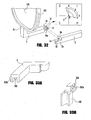
- means for limiting range of rotation is on opposing surface 3d. Examples of means for limiting the range of rotation are shown in Figures 18 and 32 .
- opposing surface 3d of one magnet has a protrusion 30a and opposing surface 3d of other magnet has a protrusion 30b and an indented pivot point 32.
- Groove is generally concentric to protrusion 30a and groove 31 that is generally semi-circular.
- Protrusion 30a is aligned with pivot point 32 and protrusion 30b is aligned with groove 31.
- the pivot point 32 lays on the Origin O of the X, Y, and Z axes.
- the groove 31 enables member 2 to rotate about the Z axis anywhere within Quadrant I, about 30° to the left of the Y axis in Quadrant II, and about 30° below the X axis in Quadrant IV, as shown by angle ⁇ in Figure 32 .
- protrusion 30b detaches from the groove 31 and protrusion 30a either rotates freely about pivot point 32 or becomes detached from pivot point 32 so that member 2 detaches from other member 2.
- member 2 never rotates into Quadrant III because protrusion 30b detaches from groove 31, thereby providing flexibility to withstand breakage caused by bending or pressure at the point of connection between members 2.
- Magnetic connector 1 further comprises at least one flexible tension bar or gate 30 that is attached to or integral with at least one of member 2.
- magnetic connector 1 comprises two flexible tension bar 30, one flexible tension bar attached to or integral with one member 2 and the other bar attached to or integral with the other member.
- flexible tension bar 30 is made of the same material from which member 2 is made or is made from a different material and is preferably a nonrigid material.
- flexible tension bar 30 is made from beta-titanium.
- first end of tension bar 30a has a smaller width than second end 30b to impart flexibility to tension bar 30 itself in addition to providing flexibility to members 2.
- flexible bar 30 is flexible enough that it flexes about 10-20° from resting position.
- second end of flexible tension bar is adjacent to perimeter surface of magnet 3c or housing 20.
- tension bar 30 is used in combination with means for limiting rotation such as the one shown in Figure 24B .
- Means for limiting rotation may be any means that limits rotation of magnets about axis 7.
- there is a space 50 between members such that ends of members 2a, 2b do not substantially touch until pressure or force is exerted against members 2.
- magnets 3 rotate about axis 7 causing ends of members 2a, 2b to substantially engage each other.
- members 2 When ends of members 2a, 2d substantially engage each other, members 2 will disengage and break away when magnets 3 rotate greater than about 110°. If pressure is reduced before disengagement of magnets 3, magnetic tension bar will act as a spring that will re-align magnets 3 and members 2.
- means for limiting rotation also imparts to magnets self-alignment such that if pressure or force is exerted against magnets 3, magnets will substantially re-align so that members 2 are also substantially re-aligned when pressure or force is removed.
- one of magnets 3 is a magnetically reactive surface such that the other magnet 3 is attracted thereto.
- magnet 3 is of a size and strength to attach to magnetically reactive surface while at the same time having a strength that does not interfere with the functionality of the claimed invention.
- magnetically attractive material must have a degree of attractiveness that is substantially similar to that of magnets 3, and must have a magnetic strength to weight ratio that is substantially similar to the ratio found in connectors comprising a pair of magnets 3.
- a protective layer (not shown) to protect the magnets 3 and/or opposing surfaces 3d from wear and corrosion caused by contact and frictional engagement.
- Protective layer is either directly applied to opposing surface of magnet 3d in examples where magnet 3 is positioned on members 2 or applied to an area of members in which magnets are embedded.
- the protective layer may be rubber, plastic, metal, oil, or a cushion means positioned between magnets.
- the thickness of the protective layer ranges from about 0.2 mm to about 0.5 mm. However, the protective layer must not be so thick that it interferes with the magnetic capabilities of the claimed invention.
- each magnet 3 comprises more than one magnet, as shown in Figure 19 .
- Magnets 3 comprising multiple magnets are positioned substantially parallel to each other in a plane. Multiple magnets are either in direct contact with each other as shown in Figure 19 or may be spaced apart from each other as shown in Figure 23 .
- magnets 3 are in a horizontal or vertical plane.
- magnets 3 comprising more than one magnet are attracted to each other by an attractive force created when multiple magnets are in substantial proximity to each other.
- magnets 3 comprising more than one magnet are permanently affixed to each other, such as by glue or epoxy.
- the magnetic strength of magnetic connector 1 also increases. Therefore, in an example, intended use or function of the eyewear 10 comprising magnetic connector 1 may determine the number of magnets comprising each magnet 3.
- the invention is a magnetic connector 1 comprising first and second magnets 3 of substantially the same polarity.
- Magnetic connectors 1 may have any of the features described above and are positioned in or on members of eyewear 10.
- Magnetic connector 1 further comprises a locking mechanism 40 that locks members 2 together, as shown in Figure 23 .
- Locking mechanism 40 comprises two parts 40a, 40b , one located on one member and the other located on the other member. When locking member 40 is substantially engaged and magnets 3 are positioned in proximity to each other sufficient to create a field of magnetic repulsion, members 2 are pushed away from each other and a tension is created that secures the locking mechanism 40, thereby securing the connection of first and second members.
- locking mechanism is a lock and key configured to engage each other and further secured when magnetic repulsion pushes lock and key into engagement and substantially aligns members in a substantial parallel direction away from each other.
- locking mechanism 40 is a hook and latch, the hook hooking the latch and being tensioned when magnetic repulsion pushes members 2 away from each other to secure the connection between members 2 substantially aligning members in a substantially parallel direction.
- locking mechanism 40 is a T-bar and hook, the T-bar configured to engage hook and being tensioned when magnetic repulsion pushes members 2 away from each other to secure the connection between members 2, substantially aligning members in a substantial parallel direction.
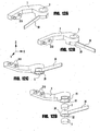
- the invention is a magnetic hinge adapter 600 for use with eyewear 10 to provide a mechanism for retrofitting the magnetic connector 1 of the present invention into eyewear 10 equipped with conventional connectors 610 such as a miniature screw hinge.
- the magnetic hinge adapter 600 comprises at least one adapter piece 601 comprising a magnetic surface 602 and at least one platform 603 having a hole 604 therein. Magnetic surface 602 creates a magnetic field of attraction that magnetically connects members 2 of eyewear 10 at connection points.
- the adapter piece 601 may be made of any material known to those skilled in the art for use in eyewear 10, including plastic, titanium, aluminum, or any other metal.
- the adapter piece 601 comprises a magnetic surface 602.
- the entire adapter piece 601 is magnetized.
- Platform 603 is for mounting adapter piece 601 onto member 2 and is sized and shaped to integrate with the screw hinge 601.
- Platform 603 has a hole 604 that substantially aligns with a screw hole 614 in the platform 613 of the screw hinge 610 when the platforms 603, 613 are overlapped.
- Each hole 604, 614 is capable of receiving a securing means 615 such as a rivet that has a diameter sized to substantially fit in the holes 604, 614 in the platforms 603, 613.
- the securing means 615 may comprise at least one ridge 615a to further secure securing means 615 in holes 604, 614.
- Securing means 615 may be made of any suitable material, including for examples, plastic or metal.
- magnetic hinge adapter 600 further comprises a second adapter piece 601. Magnetic surfaces 602 of adapter pieces have substantially opposite polarities. The magnetic attractive force between magnetic surfaces 602 of adapter pieces magnetically connects members 2 while eliminating the need for conventional connectors 610 such as screw hinges.
- magnetic connector 1 in combination with eyewear 10 are described below and are shown in Figures 1-8 , 14-16 , 26-29 , and 33-34 . Even where not specifically described, the specific examples described below may incorporate any of the features described above as long as the feature does not interfere with the intended function of the specific eyewear 10.
- eyewear 10 comprises an eyewire 102 and two sets of member frame fronts 502 magnetically connected to member temple bar 202 by a magnetic connector 1 positioned therebetween.
- frame front 502 is continuous or integral with eyewire 102.
- frame fronts 502 are substantially parallel.
- Each frame front 502 has first and second ends 502a, 502b and is attached at one end to an end of eyewire 102.
- Each temple bar 202 has first and second ends 2902a, 202b.
- member temple bars 202 are in an open or fully extended position such that temple bars 202 are substantially parallel to each other and are about 90° from the plane in which lenses 110 are positioned.
- Magnets 3 comprising magnetic connector 1 are of substantially opposite polarities.
- First end of temple bar 202a is substantially adjacent to and aligned with second end of frame front 102b when magnets 3 comprising magnetic connector 1 are substantially aligned and are in sufficient proximity to each other to create a magnetic field of attraction to magnetically connect and align member temple bar 202 and member frame front 502 such that temple bar 202 is maintained in an open position by magnets 3 comprising magnetic connector.
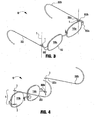
- Figures 3 and 14-16 show different views of eyewear 10 with members temple bars 202 and frame fronts 202 magnetically connected by magnetic connector 1, and Figure 4 shows temple bars 202 and frame fronts 501 detached.
- Figure 4 shows an exploded perspective view of magnetic connector in combination with a pair of eyeglasses 10.
- First end 202a of temple bar is substantially adjacent to and aligned with second end 502b of frame front when magnets 3 comprising magnetic connector 1 are substantially parallel to each other in a horizontal plane.
- Magnets 3 are in sufficient proximity that their magnetic fields interact, thereby creating a magnetic field of attraction.
- the attractive force magnetically connects and aligns member temple bar 202 with member frame front 502 such that temple bar 202 is maintained in the open position.
- FIG. 7 and 34 show perspective views of eyewear 10 with frame fronts 502 and temple bars 202 magnetically connected by magnetic connector 1
- Figure 8 shows an exploded perspective view showing magnetic connectors 1 between frame fronts 502 and temple bars 202.
- Magnets 3 are substantially parallel to each other in a vertical plane.
- First end of temple bar 202a is substantially adjacent to and aligned with second end of frame front 502b when magnets 3 are in sufficient proximity to each other to create a magnetic field of attraction to magnetically connect and align member temple bar 202 with member frame front 502 such that temple bar 202 is open.
- first end 502a of frame front is either integral with or attached to eyewire 102.
- second end of temple bar 202b may be either an L-shaped configuration or a semicircular configuration.
- the semicircular configuration in combination with the flexible hinge 30 and magnetic connectors 1 described above provides a secure, lightweight eyewear 10 that substantially eliminates the lateral pressure commonly exerted on the temple, ear, or mastoid bone of the wearer by eyewear 10 comprising temple bars 202 with semicircular configurations.
- FIG. 1 shows an example of a magnetic connector 1 that is magnetically connected to rimless eyewear.
- Each frame front 502 comprises at least one prong 310 projecting from a surface of frame front 502 near frame front's first end 502a.
- prongs and methods of attachment to lenses are generally defined and described in U.S. Patent Application Serial No. 11/458,239, filed July 18, 2006 .
- prongs 310 are designed to accommodate and fit within or pass through corresponding connecting cavities or holes in lens 110.
- the connecting cavities or holes are positioned near or about the outer perimeter of lens 110, out of the line of vision of lenses.
- Frame front 502 may either be attached to front 110a or rear surfaces of lenses 110b.
- prongs 310 project from a rear surface of frame front 502 through the lenses 110 towards the rear surface of lenses 110b.
- prongs 310 project from a front surface of frame front through the lenses 110 towards the front surface of lenses 110a.
- eyewear comprises at least one set of magnets 3 comprised of at least two magnets.
- One member of the pair is positioned within a peripheral hole or cavity in lens, as defined and described in U.S. Patent Application Serial No. 11/458,239, filed July 18, 2006 .
- Other member of the magnet pair is positioned in or on first end of temple bar 202a, the magnets 3 of the pair being of substantially opposite polarities and being generally alignable to removably attach temple bar 202 and lenses.
- second ends of frame fronts 502b are magnetically connected to temple bars 202 as described above.
- Eyewear 10 optionally comprises a flexible hinge bar 30 and a means for limiting rotation as shown in Figure 24 .
- temple bar 202 In the open position, as defined above and shown as the solid lines in Figure 24A , temple bar 202 is substantially aligned with frame front 502, with angle ⁇ being about 90°.
- member rotates about axis so that angle ⁇ is greater than about 150°, as shown by the dashed lines in Figure 24 .
- means for limiting rotation comprises a contacting surface on ends of members 2 such that when contacting surfaces come into contact, members 2 will disengage if pressure is not substantially removed.
- Flexible hinge bar 30 provides flexibility to member 2 such that when pressure is released or removed, magnets 3 substantially realign, thereby causing members 2 to realign so that members 2 are in the substantial open position. When contacting surfaces come into contact and are forced against each other, members 2 disengage.
- magnets 3 are positioned substantially parallel to each other in a vertical plane and have opposing surfaces 3d that are substantially complementary, the angle of opposing surfaces 3d being about 45°.
- Magnets 3 are positioned in or on members 2 as described above, and members 2 are substantially aligned when magnets 3 are in sufficient proximity to create a magnetic field of attraction between members 3.
- At least one magnet 3 is able to swivel about axis 7 to move member swivel temple bar 22 from opened ( Figure 36B ) to closed ( Figure 36C ) positions.
- Figure 36D shows the swivel orientation of members 2.
- Swivel temple bar 222 rotates about axis 7 in a substantial conical or funnel-type pattern rather than rotating in a plane that is substantially perpendicular to the plane of the lens 110 (in which conventional temple bars such as those shown in Figures 1 to 6 , e.g., rotate). Swivel temple bars 222 are maximally rotated at the open position, which is about 90° from the plane of the lenses 110, and at the closed position, which is substantially parallel to the plane of the lenses 110 and in substantial proximity to the lenses 110. At both maximal rotations, swivel temple bars 222 are in substantially the same plane that traditional temple bars 202 are in when open and closed, respectively.
- magnetic connector 1 comprises male 303a and female 303b magnet that magnetically connect member eyewire 102 and member frame front 502 as shown in Figure 33 .
- Eyewire 102 has a groove for engagement of an edge of a lens 110.
- One of the magnets 303a, 303b is positioned in or on the eyewire 102 ( Figure 33B ) and the other magnet 303a, 303b is positioned in or on the frame front 502 ( Figure 33A ).
- the means of positioning magnets 303a, 303b in or on eyewire 102 and frame front 502 is determined, at least in part, by the materials from which these members are made.
- male magnet 303a is positioned on eyewire 102 and female magnet 303b is positioned on frame front 502, although in other examples, female magnet 303b could be positioned on eyewire 102 and male magnet 303a could be positioned on frame front 502.
- Magnets 303a, 303b are substantially aligned so that male magnet 303a fits into female magnet 303b.
- magnets are positioned substantially parallel to each other in a horizontal plane, but in other examples, magnets are positioned substantially parallel to each other in a vertical plane.
- each magnet 303a, 303b comprising magnetic connector 1 comprises more than one magnet to increase the strength of magnetic attraction.
- male and female magnets 303a, 303b further comprise a cushion mechanism 304 that further secures the connection between magnets 303a, 303b, thereby increasing the strength of the connection between member eyewire 102 and member frame front 502.
- the cushion mechanism 304 may be, for examples, a rubber sphere cushion ( Figure 33D ) or a spring cushion ( Figure 33C ).
- male magnet 303a has rubber sphere or spring cushions 304 that lock into or engage with corresponding sockets 305 in female magnet 303b that are substantially aligned with cushions 304 in male magnet.
- cushion 304 compresses and then expands into sockets 305 when male and female magnets 303a, 303b are fully engaged.
- eyewear 10 comprises an eyewire having ends 102a, 102b that are magnetically connected by magnetic connector 1.
- Figure 26 shows the eyewear 10 magnetically connected.
- Figure 27A shows an exploded perspective view of an example of an eyewire 102 comprising three pieces that are connected by magnetic connectors 1 located both nasally and temporally.
- Figure 27B shows a perspective view of a unitary eyewire 102 having magnetic connectors 1 located temporally.
- magnets 3 are positioned substantially parallel to each other in a horizontal plane but magnets 3 could also be positioned substantially parallel to each other in a vertical plane. Further, each magnet 3 could comprise more than one magnetic to increase strength of magnetic attraction.
- Eyewire 102 comprises at least one piece.
- magnets 3 are sintered and compressed around ends of eyewire 102a, 102b.
- lenses 110 are secured in eyewire when ends of eyewire 102a, 102b are magnetically connected by magnetic connectors 1.
- Magnetic connection of ends of eyewire 102a, 102b permits easy removal and replacement of lenses 110, such as to change the aesthetic appearance of eyewear or to replace damaged lenses or to interchange untinted lenses and tinted lenses, such as to accommodate use of eyewear indoors and outdoors, or in the light and dark.
- additional lenses could be inserted over each of first lenses to add tinted lenses.
- one magnetic connector 20 connects nose pad 402a and nose pad arm 402b and a second magnetic connector connects nose pad arm 402b to eyewire 102 thereby enabling the nose pad 402a and/or nose pad arm 402b to be removably attached for easy replacement.
- nose pad arm 402b is connected to eyewire 102 by conventional means and to nose pad 402a by a magnetic connector 1.
- Figure 28 shows the nose pads 402a and nose pad arms 402b magnetically connected and Figure 29 shows an exploded view showing the component parts.
- Each nose pad 402a is preferably made of a pliable, hypo-allergenic material, such as for examples plastic, rubber, vinyl, silicone, titanium, stainless steel, polycarbonate, or a combination thereof.
- Nose pad 402a is any thickness that does not interfere with its function, but must not be so thick that it interferes with the magnetic strength of the magnetic connector.
- Magnets 3 have opposite polarities and are substantially aligned so that nose pad 402a is substantially centered over nose pad arm 402b to position the eyeglasses 10 on the wearer's nose.
- nose pad 402a has a pocket into which magnet 3 is inserted.
- magnet 3 is adhered by any means known in the art to an outer surface of nose pad 402a, or nose pad 402a may be formed around magnet 3.
- the means of adhering or attaching magnets 3 to the nose pad 402a or nose pad arm 402b may be determined, at least in part, by the materials from which the nose pad and nose pad arm are made, and with concern to maintain magnetic properties of magnets.
- nose pad arm 402b has two ends, one end for attachment to eyewire 102 and one end for attachment to nose pad 402a.
- nose pad arm 402b is a J-shaped wire.
- nose pad arm 402b is adjustable so that the angle of the nose pad arm 402b can be adjusted so that nose pad 402a fits substantially flush against a surface of the wearer's nose.
- one end of nose pad arm is magnetically attached to eyewire 102 by a magnetic connector 1, but in other examples (not shown) nose pad arm 402b is permanently attached or connected to eyewire 102 such as by welding, soldering, gluing, or the like.
- nose pad arm has a magnet 3 that is magnetically attracted to a magnet in or on nose pad 402a, described below.
- Nose pad arms 402b are substantially opposed and rest the mass of the eyewear on the sides of the wearer's nose.
- J-shaped wire of nose pad arm 402b has a socket on first end to which a protrusion on the nose pad 402a is inserted.
- Protrusion may be either a notch or a notch having a magnet 3 therein that is magnetically attracted to a magnet 3 having a substantial opposite polarity and positioned in or on nose pad ann 402b for magnetic connection of nose pad 402a of nose pad arm 402b.
- magnetic connector 1 is used in combination with banded eyewear such as goggles, for example, to magnetically connect band 60 to eyewire 102 or frame front 502.
- Band 60 may be either a linear wire band or a flat strap band.
- One magnet 3 of magnetic connector 1 is either positioned in or on frame front 102 and other magnet 3 is either positioned in or on ends of band 60.
- magnet 3 is located in an end of frame front or is embedded within lens.
- magnet 3 is sewn within fabric band 60 or is bonded to band 60 with glue or epoxy.
- magnet 3 is sintered and compressed around ends of band member 60.
Landscapes
- Physics & Mathematics (AREA)
- Health & Medical Sciences (AREA)
- General Physics & Mathematics (AREA)
- Ophthalmology & Optometry (AREA)
- Optics & Photonics (AREA)
- Details Of Connecting Devices For Male And Female Coupling (AREA)
- Eyeglasses (AREA)
Claims (15)
- Magnet-Verbindungsstück (1) zum schwenkbaren Verbinden zweier Bauteile (2) an einer Verbindungsstelle einer Brille, wobei das Verbindungsstück (1) folgendes umfasst:erste und zweite Magnete (3), die in oder auf ersten bzw. zweiten Bauteilen (2) der Brille im Wesentlichen nahe einer Verbindungsstelle zwischen den Bauteilen (2) positioniert sind, wobei die Magnete (3) im Wesentlichen entgegengesetzte Polaritäten aufweisen, und sie im Wesentlichen parallel zueinander in einer Ebene positioniert sind, und sich um eine Achse (7) drehen, die Magnete (3) einander so nahe sind, dass sie ein anziehendes Magnetfeld erzeugen, wodurch sie die Bauteile (2) im Wesentlichen miteinander verbinden, das Verbindungsstück (1) zudem mindestens ein Gehäuse (20) aufweist, das an mindestens einem der Bauteile (2) befestigt ist, und einer der jeweiligen Magnete (3) in dem jeweils mindestens einen Gehäuse (20) angeordnet ist, dadurch gekennzeichnet, dass mindestens ein Gehäuse (20) ein Dehnungsstück (23) aufweist, das den Durchmesser von Gehäuse (20) erweitert, wenn sich die Magneten (3) darin befinden.
- Magnet-Verbindungsstück (1) nach Anspruch 1, wobei die ersten und zweiten Bauteile (2) jeweils ein Ende (102a, 102b) aufweisen, wobei sich die Verbindungsstelle im Wesentlichen nah bei den Enden (102a, 102b) befindet.
- Magnet-Verbindungsstück (1) nach Anspruch 1, wobei einer der Magnete (3) eine magnetisch reaktive Oberfläche ist.
- Magnet-Verbindungsstück (1) nach Anspruch 1, zudem umfassend eine Schutzschicht, die eine gegenüber befindliche Oberfläche von Magnet (3) vor Verschleiß schützt, der durch einen Reibschluss der gegenüber befindlichen Oberflächen verursacht wird.
- Magnet-Verbindungsstück (1) nach Anspruch 1, wobei eines der Bauteile (2) eine Gestell-Vorderseite (502) mit ersten und zweiten Enden (502a, 502b) ist, und das andere Bauteil ein Bügel (202) mit ersten und zweiten Enden (202a, 203b) ist, wobei einer der Magnete in oder auf der Gestell-Vorderseite (502) im Wesentlichen nah bei dem ersten Ende positioniert ist, und der andere Magnet in oder auf dem Bügel (202) im Wesentlichen nah bei dem ersten Ende positioniert ist, wobei die Magneten das anziehende Magnetfeld erzeugen, wenn die ersten Enden hinreichend nah zueinander positioniert sind.
- Magnet-Verbindungsstück (1) nach Anspruch 1, wobei eines der Bauteile (2) eine Nasenauflage (402a) ist, und das andere Bauteil (2) ein Nasenauflagearm (402b) ist, wobei einer der Magneten (3) in oder auf der Nasenauflage (402a) positioniert ist, und der andere Magnet (3) in oder auf dem Nasenauflagearm (402b) positioniert ist, wobei die Magneten (3) das anziehende Magnetfeld erzeugen, wenn Nasenauflage (402a) und Nasenauflagearm (402b) hinreichend nah zueinander positioniert sind.
- Magnet-Verbindungsstück (1) nach Anspruch 1, wobei eines der Bauteile (2) ein erstes Ende eines Bügeldrahts (102) ist, und das andere Bauteil (2) ein zweites Ende des Bügeldrahts (102) ist, einer der Magneten (3) in oder auf dem ersten Ende des Bügeldrahts (102) positioniert ist, und der andere Magnet (3) in oder auf dem zweiten Ende des Bügeldrahts (102) positioniert ist, und die Magneten (3) das anziehende Magnetfeld erzeugen, wenn die Enden des Bügeldrahts (102) hinreichend nahe zueinander positioniert sind.
- Magnet-Verbindungsstück (1) zum schwenkbaren Verbinden zweier Bauteile (2) an einer Verbindungsstelle einer Brille, wobei das Verbindungsstück (1) Folgendes umfasst:a. zwei im Wesentlichen parallele Magnete (3), die in einer Ebene positioniert sind und sich um eine Achse drehen, wobei die Magnete (3) im Wesentlichen die gleiche Polarität aufweisen, einer der Magnete (3) in oder auf einem ersten Bauteil (2) der Brille positioniert ist, und der andere Magnet (3) in oder auf einem zweiten Bauteil (2) der Brille positioniert ist, wobei die Magneten (3) hinreichend nahe zueinander positioniert sind, dass ein abstoßendes Magnetfeld erzeugt wird, das die Bauteile voneinander abstößt;b. mindestens ein Gehäuse (20), das an mindestens einem der ersten und zweiten Bauteile (2) befestigt ist, wobei einer der jeweiligen Magnete (3) in dem jeweils mindestens einen Gehäuse (20) angeordnet ist;
dadurch gekennzeichnet, dass das mindestens eine Gehäuse (20) ein Dehnungsstück (23) aufweist, das den Durchmesser von Gehäuse (20) erweitert, wenn sich die Magneten (3) darin befinden; undc. einen Verriegelungsmechanismus (40), der zwei Teile (40a, 40b) umfasst, von denen sich eines der Teile auf einem der Bauteile (2) befindet, und das andere Teil sich auf dem anderen Bauteil (2) befindet, wobei die Abstoßung die Bauteile (2) voneinander abstößt und eine Zugspannung zwischen den Teilen (40a, 40b) des Verriegelungsmechanismus (40) erzeugt, wenn die Teile im Wesentlichen ineinander greifen, wobei die Zugspannung die Bauteile (2) verbindet. - Magnet-Verbindungsstück (1) nach Anspruch 8 oder 1, wobei sich die Magneten (3) in einer Horizontalebene befinden.
- Magnet-Verbindungsstück (1) nach Anspruch 8 oder 1, wobei sich die Magneten (3) in einer Vertikalebene befinden.
- Magnet-Verbindungsstück (1) nach Anspruch 8 oder 1, zudem umfassend eine Einrichtung zum Begrenzen des Drehbereichs der Bauteile (2) um die Achse (7).
- Magnet-Verbindungsstück (1) nach Anspruch 8 oder 1, wobei mindestens einer der Magneten (3) mindestens zwei Magneten umfasst.
- Magnet-Verbindungsstück (1) nach Anspruch 8 oder 1, zudem umfassend mindestens ein elastischen Steg (30), der an mindestens einem der Bauteile (2) befestigt ist oder einstückig damit ist, wobei der elastische Steg (30) die Drehung der Bauteile (2) um die Achse (7) begrenzt, damit die Bauteile (2) weitgehend zueinander ausgerichtet sind.
- Brillengläserpaar (10) nach Anspruch 8, wobei der Verriegelungsmechanismus (40) einer der Folgenden ist:a. Schloss-Schlüssel-Mechanismus, wobei das Schloss auf einem der gegenüber befindlichen Bauteile (2) sitzt, und der Schlüssel auf dem anderen gegenüber befindlichen Bauteil (2) sitzt;b. Haken-Riegel-Mechanismus, wobei der Haken auf einem der gegenüber befindlichen Bauteile (2) sitzt, und der Riegel auf dem anderen gegenüber befindlichen Bauteil (2) sitzt;c. T-Steg-Hakenmechanismus, wobei der T-Steg auf einem der gegenüber befindlichen Bauteile (2) sitzt, und der Haken auf dem anderen gegenüber befindlichen Bauteil (2) sitzt.
- Brillengläserpaar (10), umfassend:a. erste und zweite Bauteile (2), die im Wesentlichen einander gegenüber und zueinander ausgerichtet sind;b. ein Magnet-Verbindungsstück (1) nach einem der vorhergehenden Ansprüche.
Applications Claiming Priority (2)
| Application Number | Priority Date | Filing Date | Title |
|---|---|---|---|
| US74985105P | 2005-12-13 | 2005-12-13 | |
| PCT/US2006/062010 WO2007070829A1 (en) | 2005-12-13 | 2006-12-13 | Screwless magnetic eyewear |
Publications (2)
| Publication Number | Publication Date |
|---|---|
| EP1969418A1 EP1969418A1 (de) | 2008-09-17 |
| EP1969418B1 true EP1969418B1 (de) | 2014-03-12 |
Family
ID=37776475
Family Applications (1)
| Application Number | Title | Priority Date | Filing Date |
|---|---|---|---|
| EP06840234.6A Active EP1969418B1 (de) | 2005-12-13 | 2006-12-13 | Schraubenlose magnetische brille |
Country Status (5)
| Country | Link |
|---|---|
| US (1) | US7794080B2 (de) |
| EP (1) | EP1969418B1 (de) |
| CA (1) | CA2632748A1 (de) |
| HK (1) | HK1124668A1 (de) |
| WO (1) | WO2007070829A1 (de) |
Cited By (1)
| Publication number | Priority date | Publication date | Assignee | Title |
|---|---|---|---|---|
| US11137621B1 (en) | 2017-12-05 | 2021-10-05 | Snap Inc. | Magnetic temple hinge for eyewear |
Families Citing this family (42)
| Publication number | Priority date | Publication date | Assignee | Title |
|---|---|---|---|---|
| US20090195747A1 (en) * | 2008-02-04 | 2009-08-06 | Insua Luisa M | Interchangeable eyeglass temples |
| CN101956757B (zh) * | 2009-07-15 | 2012-11-21 | 鸿富锦精密工业(深圳)有限公司 | 铰接装置 |
| WO2011041733A1 (en) * | 2009-10-02 | 2011-04-07 | Oakley, Inc. | Eyeglass with interchangeable ornamentation |
| US8894200B2 (en) | 2010-06-30 | 2014-11-25 | Addo Industries, Llc | Innovative and aesthetic alternative to traditional spectacle correction |
| US8177360B2 (en) * | 2010-09-13 | 2012-05-15 | B. Robinson Optical | Magnetic eyeglass hinge |
| WO2012068538A2 (en) * | 2010-11-18 | 2012-05-24 | Collard David J | Magnetic eyewear retention systems |
| JPWO2012096248A1 (ja) | 2011-01-11 | 2014-06-09 | 東レバッテリーセパレータフィルム株式会社 | 多層微多孔膜、かかる膜の製造方法、およびかかる膜の使用 |
| US8875346B2 (en) * | 2011-06-28 | 2014-11-04 | Oakley, Inc. | Hinge assembly for eyewear |
| DE102011108336A1 (de) * | 2011-07-25 | 2013-01-31 | Marianne Wolff | Brille |
| WO2013067480A2 (en) * | 2011-11-03 | 2013-05-10 | Phyzics Properties, Inc. | Magnetic hinge |
| WO2013118162A1 (en) * | 2012-02-06 | 2013-08-15 | Aoyama Optical Co., Ltd. | Eyeglasses with forefront hanging glasses |
| TWI563313B (en) * | 2012-05-30 | 2016-12-21 | Ags Global Marketing Inc | Eyeglasses |
| CN103513442B (zh) * | 2012-06-20 | 2015-03-25 | 雅德视国际股份有限公司 | 眼镜 |
| ITBL20120005A1 (it) * | 2012-07-10 | 2014-01-11 | Sergio Soppelsa | Occhiale con aste e/o spezzoni di ponte ad unione ed articolazione magnetica |
| US20160100676A1 (en) * | 2012-07-27 | 2016-04-14 | Freebit As | Ear-mounted device |
| US8832904B2 (en) | 2012-09-04 | 2014-09-16 | Armand Kidouchim | Eye wear hinge and process for assembly |
| US9638934B2 (en) | 2012-09-04 | 2017-05-02 | Armand Kidouchim | Eyewear hinge and process for assembly |
| USD778979S1 (en) * | 2012-12-11 | 2017-02-14 | Luxottica S.R.L. | Temples for spectacles |
| ITBL20130001A1 (it) * | 2013-01-21 | 2014-07-22 | Sergio Soppelsa | Occhiale con astine a snodo magnetico e con spina di posizionamento |
| US20150070647A1 (en) * | 2013-09-12 | 2015-03-12 | Chase Denison | Eyewear Frame |
| USD745083S1 (en) | 2013-12-20 | 2015-12-08 | Oakley, Inc. | Set of eyeglass components |
| JP2015141219A (ja) * | 2014-01-27 | 2015-08-03 | 株式会社東京メガネ | 眼鏡 |
| USD741943S1 (en) * | 2014-03-20 | 2015-10-27 | Silhouette International Schmied Ag | Eyeglasses |
| FR3020472B1 (fr) * | 2014-04-25 | 2017-09-01 | Marc-Antoine Rubaud | Dispositif de connexion de branches de lunettes sur la face frontale |
| FR3021125A1 (fr) * | 2014-05-13 | 2015-11-20 | Intech Auvergne | Dispositif de jonction des branches sur le cadre d'une paire de lunettes |
| USD776751S1 (en) | 2014-06-27 | 2017-01-17 | Google Inc. | Interchangeable eyewear assembly |
| USD751631S1 (en) * | 2014-07-14 | 2016-03-15 | J.S. Benjamin Llc | Eyeglass hinge |
| US9341865B2 (en) | 2014-07-23 | 2016-05-17 | Brent Sheldon | Eyewear having magnetic clip-on lenses |
| US9395561B2 (en) | 2014-07-23 | 2016-07-19 | Brent Sheldon | Eyeglasses having flip-up lenses |
| US9851567B2 (en) | 2014-08-13 | 2017-12-26 | Google Llc | Interchangeable eyewear/head-mounted device assembly with quick release mechanism |
| USD757158S1 (en) | 2014-08-26 | 2016-05-24 | Silhouette International Schmied Ag | Eyewear |
| US10261338B2 (en) | 2015-01-15 | 2019-04-16 | Addo Industries, Llc | Eyewear comprising suspension system for nose and ears |
| US9482883B1 (en) * | 2015-04-15 | 2016-11-01 | Snapchat, Inc. | Eyewear having linkage assembly between a temple and a frame |
| US9482882B1 (en) | 2015-04-15 | 2016-11-01 | Snapchat, Inc. | Eyewear having selectively exposable feature |
| US9726904B1 (en) | 2015-09-29 | 2017-08-08 | Snap Inc. | Eyewear with conductive temple joint |
| CN205720936U (zh) * | 2016-05-24 | 2016-11-23 | 谢隽业 | 一种连接稳固的眼镜架的磁性连接结构 |
| US9829719B1 (en) * | 2016-08-01 | 2017-11-28 | Asher Neren | Eyeglasses assembly comprising frame and interchangeable side pieces |
| US10993515B1 (en) | 2017-08-28 | 2021-05-04 | Snap Inc. | Carry case for rechargeable eyewear devices |
| US10718954B2 (en) * | 2017-09-18 | 2020-07-21 | Danielle Ringle | Modular eyewear |
| USD948600S1 (en) * | 2020-04-21 | 2022-04-12 | Lindberg A/S | Spectacle hinge |
| FR3113956A1 (fr) * | 2020-09-04 | 2022-03-11 | F & H | Dispositif de fixation pour monture de lunettes. |
| US11906818B1 (en) * | 2022-08-18 | 2024-02-20 | Michael Renee Rodarte | Earpiece-less eyeglasses |
Citations (2)
| Publication number | Priority date | Publication date | Assignee | Title |
|---|---|---|---|---|
| EP1020752A1 (de) * | 1999-01-13 | 2000-07-19 | Charmant Co., Ltd. | Drehmechanismus eines Bügels mit Bezug zu einem Gestellhalter und Brille mit diesem Drehmechanismus |
| JP2004109841A (ja) * | 2002-09-20 | 2004-04-08 | Sanriibu:Kk | メガネフレームの連結部の構造 |
Family Cites Families (12)
| Publication number | Priority date | Publication date | Assignee | Title |
|---|---|---|---|---|
| US3422449A (en) * | 1964-05-04 | 1969-01-14 | Harry Rinnman | Eyeglasses with adjustable magnetically attached temples |
| US3264678A (en) | 1965-10-04 | 1966-08-09 | Alfred F Parmelee | Magnetic hinge pin assembly for eyeglass structure |
| US5682222A (en) | 1995-12-18 | 1997-10-28 | Chao; Richard | Spectacle frame having magnetic coupling |
| JPH10284317A (ja) * | 1997-04-08 | 1998-10-23 | Fuaa Seal Kikaku:Kk | 連結部の構造 |
| US5988811A (en) | 1998-05-27 | 1999-11-23 | Kuo-Sheng Ku | Nose pads for spectacles |
| JP4097824B2 (ja) | 1998-07-06 | 2008-06-11 | 株式会社和真 | 多焦点用眼鏡枠 |
| US6550913B2 (en) | 1998-11-02 | 2003-04-22 | Gary Martin Zelman | Auxiliary eyewear attachment methods and apparatus |
| US6217170B1 (en) | 2000-06-30 | 2001-04-17 | Yu-Teng Hsiao | Magnetic coupling system for securing a temple to an eyeglass hinge |
| CA2321318C (en) * | 2000-10-02 | 2005-12-06 | Go Simon Sunatori | Eyeglass frame with magnetic hinges |
| ITMI20030105A1 (it) | 2003-01-24 | 2004-07-25 | Optigen Optical Group S R L | Montatura per occhiali. |
| US6736504B1 (en) | 2003-04-29 | 2004-05-18 | James Hermsen | Hingeless eyeglasses |
| FR2885230B1 (fr) * | 2005-04-27 | 2008-02-01 | Rip Curl Internat Pty Ltd | Monture de lunettes de securite |
-
2006
- 2006-12-13 US US11/610,245 patent/US7794080B2/en active Active
- 2006-12-13 WO PCT/US2006/062010 patent/WO2007070829A1/en active Application Filing
- 2006-12-13 EP EP06840234.6A patent/EP1969418B1/de active Active
- 2006-12-13 CA CA002632748A patent/CA2632748A1/en not_active Abandoned
-
2009
- 2009-03-16 HK HK09102475.1A patent/HK1124668A1/xx unknown
Patent Citations (2)
| Publication number | Priority date | Publication date | Assignee | Title |
|---|---|---|---|---|
| EP1020752A1 (de) * | 1999-01-13 | 2000-07-19 | Charmant Co., Ltd. | Drehmechanismus eines Bügels mit Bezug zu einem Gestellhalter und Brille mit diesem Drehmechanismus |
| JP2004109841A (ja) * | 2002-09-20 | 2004-04-08 | Sanriibu:Kk | メガネフレームの連結部の構造 |
Cited By (1)
| Publication number | Priority date | Publication date | Assignee | Title |
|---|---|---|---|---|
| US11137621B1 (en) | 2017-12-05 | 2021-10-05 | Snap Inc. | Magnetic temple hinge for eyewear |
Also Published As
| Publication number | Publication date |
|---|---|
| CA2632748A1 (en) | 2007-06-21 |
| HK1124668A1 (en) | 2009-07-17 |
| WO2007070829A1 (en) | 2007-06-21 |
| US20070132942A1 (en) | 2007-06-14 |
| EP1969418A1 (de) | 2008-09-17 |
| US7794080B2 (en) | 2010-09-14 |
Similar Documents
| Publication | Publication Date | Title |
|---|---|---|
| EP1969418B1 (de) | Schraubenlose magnetische brille | |
| US8292427B2 (en) | Screwless magnetic eyewear | |
| US6550913B2 (en) | Auxiliary eyewear attachment methods and apparatus | |
| US7320514B2 (en) | Auxiliary eyewear assembly with micromagnetic attachment | |
| US20080088791A1 (en) | Auxiliary Eyewear Assembly With Micromagnetic Attachment | |
| US6702439B1 (en) | Clip on eyeware with spring hinge | |
| EP1865363B1 (de) | Gelenksystem für Brillen | |
| US7390086B2 (en) | Clip on eyeware with insertable member | |
| US20020093621A1 (en) | Auxiliary eyewear attachment methods and apparatus | |
| US8371692B2 (en) | Pinless hinge for eyewear | |
| WO2010057165A2 (en) | Eyeframe with interchangeable lenspieces held by a magnetic closure and interchangeable lens system | |
| JP6864197B2 (ja) | コネクタ、補助デバイス、着用可能デバイス、および着用可能デバイスキット | |
| US7244022B2 (en) | Clip on eyeware with spring hinge | |
| US20050157249A1 (en) | Multipurpose eyeglass device | |
| EP1664904B1 (de) | Ablösbares magnetisches schwenksystem mit mehreren facetten | |
| CN1296193A (zh) | 一种将眼镜与夹固式遮阳镜连在一起的方法和装置 | |
| JPH10221652A (ja) | 眼鏡保護カバー | |
| KR20020073084A (ko) | 앞 걸기 안경 부착장치 | |
| US20030030770A1 (en) | Eyewear assembly including auxiliary eyeglasses | |
| CN217718307U (zh) | 一种镜架及眼镜 | |
| CA2466827A1 (en) | Connection system for securing sunglasses to eyeglasses | |
| US20060192916A1 (en) | Rimless eyewear system with magnetic retention | |
| KR100463928B1 (ko) | 보조렌즈용 브릿지 | |
| WO2003016987A1 (en) | Clip on eyeware | |
| JP2001100161A (ja) | 前掛け眼鏡及びその取付方法 |
Legal Events
| Date | Code | Title | Description |
|---|---|---|---|
| PUAI | Public reference made under article 153(3) epc to a published international application that has entered the european phase |
Free format text: ORIGINAL CODE: 0009012 |
|
| 17P | Request for examination filed |
Effective date: 20080714 |
|
| AK | Designated contracting states |
Kind code of ref document: A1 Designated state(s): AT BE BG CH CY CZ DE DK EE ES FI FR GB GR HU IE IS IT LI LT LU LV MC NL PL PT RO SE SI SK TR |
|
| REG | Reference to a national code |
Ref country code: HK Ref legal event code: DE Ref document number: 1124668 Country of ref document: HK |
|
| 17Q | First examination report despatched |
Effective date: 20091113 |
|
| RAP1 | Party data changed (applicant data changed or rights of an application transferred) |
Owner name: PHYZICS PROPERTIES, INC. |
|
| DAX | Request for extension of the european patent (deleted) | ||
| GRAP | Despatch of communication of intention to grant a patent |
Free format text: ORIGINAL CODE: EPIDOSNIGR1 |
|
| INTG | Intention to grant announced |
Effective date: 20130927 |
|
| RIN1 | Information on inventor provided before grant (corrected) |
Inventor name: ZELAZOWSKI, DENNIS |
|
| GRAS | Grant fee paid |
Free format text: ORIGINAL CODE: EPIDOSNIGR3 |
|
| GRAA | (expected) grant |
Free format text: ORIGINAL CODE: 0009210 |
|
| AK | Designated contracting states |
Kind code of ref document: B1 Designated state(s): AT BE BG CH CY CZ DE DK EE ES FI FR GB GR HU IE IS IT LI LT LU LV MC NL PL PT RO SE SI SK TR |
|
| REG | Reference to a national code |
Ref country code: GB Ref legal event code: FG4D |
|
| REG | Reference to a national code |
Ref country code: CH Ref legal event code: EP |
|
| REG | Reference to a national code |
Ref country code: AT Ref legal event code: REF Ref document number: 656671 Country of ref document: AT Kind code of ref document: T Effective date: 20140315 |
|
| REG | Reference to a national code |
Ref country code: IE Ref legal event code: FG4D |
|
| REG | Reference to a national code |
Ref country code: DE Ref legal event code: R096 Ref document number: 602006040688 Country of ref document: DE Effective date: 20140424 |
|
| REG | Reference to a national code |
Ref country code: NL Ref legal event code: VDEP Effective date: 20140312 |
|
| PG25 | Lapsed in a contracting state [announced via postgrant information from national office to epo] |
Ref country code: LT Free format text: LAPSE BECAUSE OF FAILURE TO SUBMIT A TRANSLATION OF THE DESCRIPTION OR TO PAY THE FEE WITHIN THE PRESCRIBED TIME-LIMIT Effective date: 20140312 |
|
| REG | Reference to a national code |
Ref country code: AT Ref legal event code: MK05 Ref document number: 656671 Country of ref document: AT Kind code of ref document: T Effective date: 20140312 |
|
| REG | Reference to a national code |
Ref country code: LT Ref legal event code: MG4D |
|
| PG25 | Lapsed in a contracting state [announced via postgrant information from national office to epo] |
Ref country code: FI Free format text: LAPSE BECAUSE OF FAILURE TO SUBMIT A TRANSLATION OF THE DESCRIPTION OR TO PAY THE FEE WITHIN THE PRESCRIBED TIME-LIMIT Effective date: 20140312 Ref country code: SE Free format text: LAPSE BECAUSE OF FAILURE TO SUBMIT A TRANSLATION OF THE DESCRIPTION OR TO PAY THE FEE WITHIN THE PRESCRIBED TIME-LIMIT Effective date: 20140312 Ref country code: CY Free format text: LAPSE BECAUSE OF FAILURE TO SUBMIT A TRANSLATION OF THE DESCRIPTION OR TO PAY THE FEE WITHIN THE PRESCRIBED TIME-LIMIT Effective date: 20140312 |
|
| PG25 | Lapsed in a contracting state [announced via postgrant information from national office to epo] |
Ref country code: LV Free format text: LAPSE BECAUSE OF FAILURE TO SUBMIT A TRANSLATION OF THE DESCRIPTION OR TO PAY THE FEE WITHIN THE PRESCRIBED TIME-LIMIT Effective date: 20140312 |
|
| PG25 | Lapsed in a contracting state [announced via postgrant information from national office to epo] |
Ref country code: RO Free format text: LAPSE BECAUSE OF FAILURE TO SUBMIT A TRANSLATION OF THE DESCRIPTION OR TO PAY THE FEE WITHIN THE PRESCRIBED TIME-LIMIT Effective date: 20140312 Ref country code: BG Free format text: LAPSE BECAUSE OF FAILURE TO SUBMIT A TRANSLATION OF THE DESCRIPTION OR TO PAY THE FEE WITHIN THE PRESCRIBED TIME-LIMIT Effective date: 20140612 Ref country code: IS Free format text: LAPSE BECAUSE OF FAILURE TO SUBMIT A TRANSLATION OF THE DESCRIPTION OR TO PAY THE FEE WITHIN THE PRESCRIBED TIME-LIMIT Effective date: 20140712 Ref country code: NL Free format text: LAPSE BECAUSE OF FAILURE TO SUBMIT A TRANSLATION OF THE DESCRIPTION OR TO PAY THE FEE WITHIN THE PRESCRIBED TIME-LIMIT Effective date: 20140312 Ref country code: EE Free format text: LAPSE BECAUSE OF FAILURE TO SUBMIT A TRANSLATION OF THE DESCRIPTION OR TO PAY THE FEE WITHIN THE PRESCRIBED TIME-LIMIT Effective date: 20140312 Ref country code: BE Free format text: LAPSE BECAUSE OF FAILURE TO SUBMIT A TRANSLATION OF THE DESCRIPTION OR TO PAY THE FEE WITHIN THE PRESCRIBED TIME-LIMIT Effective date: 20140312 Ref country code: CZ Free format text: LAPSE BECAUSE OF FAILURE TO SUBMIT A TRANSLATION OF THE DESCRIPTION OR TO PAY THE FEE WITHIN THE PRESCRIBED TIME-LIMIT Effective date: 20140312 |
|
| REG | Reference to a national code |
Ref country code: HK Ref legal event code: GR Ref document number: 1124668 Country of ref document: HK |
|
| PG25 | Lapsed in a contracting state [announced via postgrant information from national office to epo] |
Ref country code: AT Free format text: LAPSE BECAUSE OF FAILURE TO SUBMIT A TRANSLATION OF THE DESCRIPTION OR TO PAY THE FEE WITHIN THE PRESCRIBED TIME-LIMIT Effective date: 20140312 Ref country code: ES Free format text: LAPSE BECAUSE OF FAILURE TO SUBMIT A TRANSLATION OF THE DESCRIPTION OR TO PAY THE FEE WITHIN THE PRESCRIBED TIME-LIMIT Effective date: 20140312 Ref country code: PL Free format text: LAPSE BECAUSE OF FAILURE TO SUBMIT A TRANSLATION OF THE DESCRIPTION OR TO PAY THE FEE WITHIN THE PRESCRIBED TIME-LIMIT Effective date: 20140312 Ref country code: SK Free format text: LAPSE BECAUSE OF FAILURE TO SUBMIT A TRANSLATION OF THE DESCRIPTION OR TO PAY THE FEE WITHIN THE PRESCRIBED TIME-LIMIT Effective date: 20140312 |
|
| REG | Reference to a national code |
Ref country code: DE Ref legal event code: R097 Ref document number: 602006040688 Country of ref document: DE |
|
| PG25 | Lapsed in a contracting state [announced via postgrant information from national office to epo] |
Ref country code: PT Free format text: LAPSE BECAUSE OF FAILURE TO SUBMIT A TRANSLATION OF THE DESCRIPTION OR TO PAY THE FEE WITHIN THE PRESCRIBED TIME-LIMIT Effective date: 20140714 |
|
| PLBE | No opposition filed within time limit |
Free format text: ORIGINAL CODE: 0009261 |
|
| STAA | Information on the status of an ep patent application or granted ep patent |
Free format text: STATUS: NO OPPOSITION FILED WITHIN TIME LIMIT |
|
| PG25 | Lapsed in a contracting state [announced via postgrant information from national office to epo] |
Ref country code: DK Free format text: LAPSE BECAUSE OF FAILURE TO SUBMIT A TRANSLATION OF THE DESCRIPTION OR TO PAY THE FEE WITHIN THE PRESCRIBED TIME-LIMIT Effective date: 20140312 |
|
| 26N | No opposition filed |
Effective date: 20141215 |
|
| REG | Reference to a national code |
Ref country code: DE Ref legal event code: R097 Ref document number: 602006040688 Country of ref document: DE Effective date: 20141215 |
|
| PG25 | Lapsed in a contracting state [announced via postgrant information from national office to epo] |
Ref country code: IT Free format text: LAPSE BECAUSE OF FAILURE TO SUBMIT A TRANSLATION OF THE DESCRIPTION OR TO PAY THE FEE WITHIN THE PRESCRIBED TIME-LIMIT Effective date: 20140312 |
|
| PG25 | Lapsed in a contracting state [announced via postgrant information from national office to epo] |
Ref country code: SI Free format text: LAPSE BECAUSE OF FAILURE TO SUBMIT A TRANSLATION OF THE DESCRIPTION OR TO PAY THE FEE WITHIN THE PRESCRIBED TIME-LIMIT Effective date: 20140312 Ref country code: LU Free format text: LAPSE BECAUSE OF FAILURE TO SUBMIT A TRANSLATION OF THE DESCRIPTION OR TO PAY THE FEE WITHIN THE PRESCRIBED TIME-LIMIT Effective date: 20141213 |
|
| REG | Reference to a national code |
Ref country code: CH Ref legal event code: PL |
|
| REG | Reference to a national code |
Ref country code: IE Ref legal event code: MM4A |
|
| PG25 | Lapsed in a contracting state [announced via postgrant information from national office to epo] |
Ref country code: IE Free format text: LAPSE BECAUSE OF NON-PAYMENT OF DUE FEES Effective date: 20141213 Ref country code: CH Free format text: LAPSE BECAUSE OF NON-PAYMENT OF DUE FEES Effective date: 20141231 Ref country code: LI Free format text: LAPSE BECAUSE OF NON-PAYMENT OF DUE FEES Effective date: 20141231 |
|
| REG | Reference to a national code |
Ref country code: FR Ref legal event code: PLFP Year of fee payment: 10 |
|
| PG25 | Lapsed in a contracting state [announced via postgrant information from national office to epo] |
Ref country code: MC Free format text: LAPSE BECAUSE OF FAILURE TO SUBMIT A TRANSLATION OF THE DESCRIPTION OR TO PAY THE FEE WITHIN THE PRESCRIBED TIME-LIMIT Effective date: 20140312 |
|
| PG25 | Lapsed in a contracting state [announced via postgrant information from national office to epo] |
Ref country code: GR Free format text: LAPSE BECAUSE OF FAILURE TO SUBMIT A TRANSLATION OF THE DESCRIPTION OR TO PAY THE FEE WITHIN THE PRESCRIBED TIME-LIMIT Effective date: 20140613 |
|
| PG25 | Lapsed in a contracting state [announced via postgrant information from national office to epo] |
Ref country code: HU Free format text: LAPSE BECAUSE OF FAILURE TO SUBMIT A TRANSLATION OF THE DESCRIPTION OR TO PAY THE FEE WITHIN THE PRESCRIBED TIME-LIMIT; INVALID AB INITIO Effective date: 20061213 Ref country code: TR Free format text: LAPSE BECAUSE OF FAILURE TO SUBMIT A TRANSLATION OF THE DESCRIPTION OR TO PAY THE FEE WITHIN THE PRESCRIBED TIME-LIMIT Effective date: 20140312 |
|
| REG | Reference to a national code |
Ref country code: FR Ref legal event code: PLFP Year of fee payment: 11 |
|
| REG | Reference to a national code |
Ref country code: FR Ref legal event code: PLFP Year of fee payment: 12 |
|
| REG | Reference to a national code |
Ref country code: DE Ref legal event code: R082 Ref document number: 602006040688 Country of ref document: DE Representative=s name: HL KEMPNER PATENTANWAELTE, SOLICITORS (ENGLAND, DE Ref country code: DE Ref legal event code: R082 Ref document number: 602006040688 Country of ref document: DE Representative=s name: HL KEMPNER PATENTANWALT, RECHTSANWALT, SOLICIT, DE |
|
| P01 | Opt-out of the competence of the unified patent court (upc) registered |
Effective date: 20230524 |
|
| PGFP | Annual fee paid to national office [announced via postgrant information from national office to epo] |
Ref country code: GB Payment date: 20231227 Year of fee payment: 18 |
|
| PGFP | Annual fee paid to national office [announced via postgrant information from national office to epo] |
Ref country code: FR Payment date: 20231227 Year of fee payment: 18 |
|
| PGFP | Annual fee paid to national office [announced via postgrant information from national office to epo] |
Ref country code: DE Payment date: 20231229 Year of fee payment: 18 |