EP1968907B1 - Chalumeau a plasma pour la fabrication de silice synthetique - Google Patents
Chalumeau a plasma pour la fabrication de silice synthetique Download PDFInfo
- Publication number
- EP1968907B1 EP1968907B1 EP06848223A EP06848223A EP1968907B1 EP 1968907 B1 EP1968907 B1 EP 1968907B1 EP 06848223 A EP06848223 A EP 06848223A EP 06848223 A EP06848223 A EP 06848223A EP 1968907 B1 EP1968907 B1 EP 1968907B1
- Authority
- EP
- European Patent Office
- Prior art keywords
- quartz glass
- glass tube
- plasma
- plasma torch
- synthetic silica
- Prior art date
- Legal status (The legal status is an assumption and is not a legal conclusion. Google has not performed a legal analysis and makes no representation as to the accuracy of the status listed.)
- Not-in-force
Links
- VYPSYNLAJGMNEJ-UHFFFAOYSA-N Silicium dioxide Chemical compound O=[Si]=O VYPSYNLAJGMNEJ-UHFFFAOYSA-N 0.000 title claims abstract description 203
- 239000000377 silicon dioxide Substances 0.000 title claims abstract description 30
- 239000000126 substance Substances 0.000 claims abstract description 84
- 230000006698 induction Effects 0.000 claims abstract description 71
- 238000002347 injection Methods 0.000 claims abstract description 57
- 239000007924 injection Substances 0.000 claims abstract description 57
- 230000008021 deposition Effects 0.000 claims abstract description 37
- 239000000758 substrate Substances 0.000 claims description 15
- 230000033001 locomotion Effects 0.000 claims description 8
- 230000037361 pathway Effects 0.000 claims 4
- 239000007789 gas Substances 0.000 abstract description 85
- IJGRMHOSHXDMSA-UHFFFAOYSA-N Atomic nitrogen Chemical compound N#N IJGRMHOSHXDMSA-UHFFFAOYSA-N 0.000 abstract description 20
- 239000010453 quartz Substances 0.000 abstract description 16
- 229910052757 nitrogen Inorganic materials 0.000 abstract description 10
- 230000007613 environmental effect Effects 0.000 abstract description 6
- 238000002955 isolation Methods 0.000 abstract description 5
- 238000000151 deposition Methods 0.000 description 33
- 238000000034 method Methods 0.000 description 24
- 239000011521 glass Substances 0.000 description 19
- 230000008569 process Effects 0.000 description 19
- 239000002245 particle Substances 0.000 description 17
- 239000004071 soot Substances 0.000 description 13
- 239000000463 material Substances 0.000 description 9
- VXEGSRKPIUDPQT-UHFFFAOYSA-N 4-[4-(4-methoxyphenyl)piperazin-1-yl]aniline Chemical compound C1=CC(OC)=CC=C1N1CCN(C=2C=CC(N)=CC=2)CC1 VXEGSRKPIUDPQT-UHFFFAOYSA-N 0.000 description 7
- 238000006243 chemical reaction Methods 0.000 description 7
- 238000013461 design Methods 0.000 description 7
- 125000002887 hydroxy group Chemical group [H]O* 0.000 description 7
- 239000005049 silicon tetrachloride Substances 0.000 description 7
- 239000003381 stabilizer Substances 0.000 description 7
- QVGXLLKOCUKJST-UHFFFAOYSA-N atomic oxygen Chemical compound [O] QVGXLLKOCUKJST-UHFFFAOYSA-N 0.000 description 6
- 230000008901 benefit Effects 0.000 description 6
- 239000002826 coolant Substances 0.000 description 6
- 239000002019 doping agent Substances 0.000 description 6
- 238000004519 manufacturing process Methods 0.000 description 6
- 239000013307 optical fiber Substances 0.000 description 6
- 239000001301 oxygen Substances 0.000 description 6
- 229910052760 oxygen Inorganic materials 0.000 description 6
- 239000002994 raw material Substances 0.000 description 5
- 239000007858 starting material Substances 0.000 description 5
- YCKRFDGAMUMZLT-UHFFFAOYSA-N Fluorine atom Chemical compound [F] YCKRFDGAMUMZLT-UHFFFAOYSA-N 0.000 description 4
- 239000012159 carrier gas Substances 0.000 description 4
- 238000001035 drying Methods 0.000 description 4
- 229910052731 fluorine Inorganic materials 0.000 description 4
- 239000011737 fluorine Substances 0.000 description 4
- 230000007062 hydrolysis Effects 0.000 description 4
- 238000006460 hydrolysis reaction Methods 0.000 description 4
- -1 hydroxyl ions Chemical class 0.000 description 4
- 239000000047 product Substances 0.000 description 4
- 229910001220 stainless steel Inorganic materials 0.000 description 4
- 239000010935 stainless steel Substances 0.000 description 4
- 230000015572 biosynthetic process Effects 0.000 description 3
- 238000012986 modification Methods 0.000 description 3
- 230000004048 modification Effects 0.000 description 3
- 230000003287 optical effect Effects 0.000 description 3
- 230000005855 radiation Effects 0.000 description 3
- 239000000376 reactant Substances 0.000 description 3
- 238000005245 sintering Methods 0.000 description 3
- XLYOFNOQVPJJNP-UHFFFAOYSA-N water Substances O XLYOFNOQVPJJNP-UHFFFAOYSA-N 0.000 description 3
- UFHFLCQGNIYNRP-UHFFFAOYSA-N Hydrogen Chemical compound [H][H] UFHFLCQGNIYNRP-UHFFFAOYSA-N 0.000 description 2
- 229910004014 SiF4 Inorganic materials 0.000 description 2
- VSCWAEJMTAWNJL-UHFFFAOYSA-K aluminium trichloride Chemical compound Cl[Al](Cl)Cl VSCWAEJMTAWNJL-UHFFFAOYSA-K 0.000 description 2
- 230000007423 decrease Effects 0.000 description 2
- 238000005137 deposition process Methods 0.000 description 2
- 238000007496 glass forming Methods 0.000 description 2
- 239000001257 hydrogen Substances 0.000 description 2
- 229910052739 hydrogen Inorganic materials 0.000 description 2
- XLYOFNOQVPJJNP-UHFFFAOYSA-M hydroxide Chemical compound [OH-] XLYOFNOQVPJJNP-UHFFFAOYSA-M 0.000 description 2
- 239000012535 impurity Substances 0.000 description 2
- 238000007689 inspection Methods 0.000 description 2
- VNWKTOKETHGBQD-UHFFFAOYSA-N methane Chemical compound C VNWKTOKETHGBQD-UHFFFAOYSA-N 0.000 description 2
- 239000000203 mixture Substances 0.000 description 2
- 238000007254 oxidation reaction Methods 0.000 description 2
- 239000012071 phase Substances 0.000 description 2
- XHXFXVLFKHQFAL-UHFFFAOYSA-N phosphoryl trichloride Chemical compound ClP(Cl)(Cl)=O XHXFXVLFKHQFAL-UHFFFAOYSA-N 0.000 description 2
- 238000012545 processing Methods 0.000 description 2
- ABTOQLMXBSRXSM-UHFFFAOYSA-N silicon tetrafluoride Chemical compound F[Si](F)(F)F ABTOQLMXBSRXSM-UHFFFAOYSA-N 0.000 description 2
- 239000007787 solid Substances 0.000 description 2
- FYSNRJHAOHDILO-UHFFFAOYSA-N thionyl chloride Chemical compound ClS(Cl)=O FYSNRJHAOHDILO-UHFFFAOYSA-N 0.000 description 2
- 238000011144 upstream manufacturing Methods 0.000 description 2
- 238000004804 winding Methods 0.000 description 2
- ZAMOUSCENKQFHK-UHFFFAOYSA-N Chlorine atom Chemical compound [Cl] ZAMOUSCENKQFHK-UHFFFAOYSA-N 0.000 description 1
- RYGMFSIKBFXOCR-UHFFFAOYSA-N Copper Chemical compound [Cu] RYGMFSIKBFXOCR-UHFFFAOYSA-N 0.000 description 1
- MYMOFIZGZYHOMD-UHFFFAOYSA-N Dioxygen Chemical compound O=O MYMOFIZGZYHOMD-UHFFFAOYSA-N 0.000 description 1
- 229910006113 GeCl4 Inorganic materials 0.000 description 1
- 229910019213 POCl3 Inorganic materials 0.000 description 1
- 235000014676 Phragmites communis Nutrition 0.000 description 1
- 229910003074 TiCl4 Inorganic materials 0.000 description 1
- 238000010521 absorption reaction Methods 0.000 description 1
- 238000013459 approach Methods 0.000 description 1
- 239000006227 byproduct Substances 0.000 description 1
- 239000000919 ceramic Substances 0.000 description 1
- 238000005229 chemical vapour deposition Methods 0.000 description 1
- 239000000460 chlorine Substances 0.000 description 1
- 229910052801 chlorine Inorganic materials 0.000 description 1
- 229910052681 coesite Inorganic materials 0.000 description 1
- 150000001875 compounds Chemical class 0.000 description 1
- 238000007596 consolidation process Methods 0.000 description 1
- 238000010924 continuous production Methods 0.000 description 1
- 229910052802 copper Inorganic materials 0.000 description 1
- 239000010949 copper Substances 0.000 description 1
- 229910052906 cristobalite Inorganic materials 0.000 description 1
- 230000003247 decreasing effect Effects 0.000 description 1
- 230000000593 degrading effect Effects 0.000 description 1
- 230000001419 dependent effect Effects 0.000 description 1
- 238000009792 diffusion process Methods 0.000 description 1
- 229910001882 dioxygen Inorganic materials 0.000 description 1
- 239000012467 final product Substances 0.000 description 1
- 239000005350 fused silica glass Substances 0.000 description 1
- 238000010438 heat treatment Methods 0.000 description 1
- 238000012423 maintenance Methods 0.000 description 1
- 230000003647 oxidation Effects 0.000 description 1
- 239000011224 oxide ceramic Substances 0.000 description 1
- 229910052574 oxide ceramic Inorganic materials 0.000 description 1
- 238000010926 purge Methods 0.000 description 1
- 230000009467 reduction Effects 0.000 description 1
- 230000008439 repair process Effects 0.000 description 1
- 238000007789 sealing Methods 0.000 description 1
- 238000004904 shortening Methods 0.000 description 1
- 229910052710 silicon Inorganic materials 0.000 description 1
- 239000010703 silicon Substances 0.000 description 1
- 239000000243 solution Substances 0.000 description 1
- 230000006641 stabilisation Effects 0.000 description 1
- 238000011105 stabilization Methods 0.000 description 1
- 229910052682 stishovite Inorganic materials 0.000 description 1
- 238000012360 testing method Methods 0.000 description 1
- IEXRMSFAVATTJX-UHFFFAOYSA-N tetrachlorogermane Chemical compound Cl[Ge](Cl)(Cl)Cl IEXRMSFAVATTJX-UHFFFAOYSA-N 0.000 description 1
- XJDNKRIXUMDJCW-UHFFFAOYSA-J titanium tetrachloride Chemical compound Cl[Ti](Cl)(Cl)Cl XJDNKRIXUMDJCW-UHFFFAOYSA-J 0.000 description 1
- 229910052905 tridymite Inorganic materials 0.000 description 1
- 238000007740 vapor deposition Methods 0.000 description 1
- 239000012808 vapor phase Substances 0.000 description 1
Images


Classifications
-
- C—CHEMISTRY; METALLURGY
- C03—GLASS; MINERAL OR SLAG WOOL
- C03B—MANUFACTURE, SHAPING, OR SUPPLEMENTARY PROCESSES
- C03B37/00—Manufacture or treatment of flakes, fibres, or filaments from softened glass, minerals, or slags
- C03B37/01—Manufacture of glass fibres or filaments
- C03B37/012—Manufacture of preforms for drawing fibres or filaments
- C03B37/014—Manufacture of preforms for drawing fibres or filaments made entirely or partially by chemical means, e.g. vapour phase deposition of bulk porous glass either by outside vapour deposition [OVD], or by outside vapour phase oxidation [OVPO] or by vapour axial deposition [VAD]
- C03B37/01413—Reactant delivery systems
- C03B37/0142—Reactant deposition burners
- C03B37/01426—Plasma deposition burners or torches
-
- H—ELECTRICITY
- H05—ELECTRIC TECHNIQUES NOT OTHERWISE PROVIDED FOR
- H05H—PLASMA TECHNIQUE; PRODUCTION OF ACCELERATED ELECTRICALLY-CHARGED PARTICLES OR OF NEUTRONS; PRODUCTION OR ACCELERATION OF NEUTRAL MOLECULAR OR ATOMIC BEAMS
- H05H1/00—Generating plasma; Handling plasma
- H05H1/24—Generating plasma
- H05H1/26—Plasma torches
- H05H1/30—Plasma torches using applied electromagnetic fields, e.g. high frequency or microwave energy
-
- H—ELECTRICITY
- H05—ELECTRIC TECHNIQUES NOT OTHERWISE PROVIDED FOR
- H05H—PLASMA TECHNIQUE; PRODUCTION OF ACCELERATED ELECTRICALLY-CHARGED PARTICLES OR OF NEUTRONS; PRODUCTION OR ACCELERATION OF NEUTRAL MOLECULAR OR ATOMIC BEAMS
- H05H1/00—Generating plasma; Handling plasma
- H05H1/24—Generating plasma
- H05H1/26—Plasma torches
- H05H1/32—Plasma torches using an arc
- H05H1/42—Plasma torches using an arc with provisions for introducing materials into the plasma, e.g. powder, liquid
-
- C—CHEMISTRY; METALLURGY
- C03—GLASS; MINERAL OR SLAG WOOL
- C03B—MANUFACTURE, SHAPING, OR SUPPLEMENTARY PROCESSES
- C03B2207/00—Glass deposition burners
- C03B2207/80—Feeding the burner or the burner-heated deposition site
- C03B2207/81—Constructional details of the feed line, e.g. heating, insulation, material, manifolds, filters
-
- Y—GENERAL TAGGING OF NEW TECHNOLOGICAL DEVELOPMENTS; GENERAL TAGGING OF CROSS-SECTIONAL TECHNOLOGIES SPANNING OVER SEVERAL SECTIONS OF THE IPC; TECHNICAL SUBJECTS COVERED BY FORMER USPC CROSS-REFERENCE ART COLLECTIONS [XRACs] AND DIGESTS
- Y02—TECHNOLOGIES OR APPLICATIONS FOR MITIGATION OR ADAPTATION AGAINST CLIMATE CHANGE
- Y02P—CLIMATE CHANGE MITIGATION TECHNOLOGIES IN THE PRODUCTION OR PROCESSING OF GOODS
- Y02P40/00—Technologies relating to the processing of minerals
- Y02P40/50—Glass production, e.g. reusing waste heat during processing or shaping
- Y02P40/57—Improving the yield, e-g- reduction of reject rates
Definitions
- the present invention relates to methods for making pure synthetic silica tubes, doped synthetic silica tubes, rods for optical fibber applications, and blanks for ultraviolet transmitting optical components. More particularly, it concerns a process for making such tubes and optical components by depositing silica with low hydroxyl content through a plasma process.
- Starter tubes can be formed by heating silica and extruding it through an aperture.
- Both starter tubes and optical fiber preforms can be made by depositing doped or undoped silica onto a target using one of several techniques such as modified chemical vapor deposition (MCVD), vapor axial deposition (VAD), outside vapor deposition (OVD).
- MCVD modified chemical vapor deposition
- VAD vapor axial deposition
- OLED outside vapor deposition
- MCVD modified chemical vapor deposition
- VAD vapor axial deposition
- OTD outside vapor deposition
- a heat source such as a gas burner or a plasma source is positioned beneath the rotating target.
- the heat source will provide the required energy for the glass-forming reactions to form glass particles.
- these deposited glass particles are ready for the next processing, drying and sintering steps such as VAD or OVD processes. If it is an MCVD process, these particles will be fused into vitreous quartz by the same heat source.
- particle sizes that are between 0.05 to 0.2 mm are ideal for the flame hydrolysis chemical reaction that is found in the OVD and VAD processes.
- These processes involve two steps namely, forming soot particles by the flame hydrolysis, and then consolidating the soot particles in a separate furnace. A slightly larger diameters of the soot particle is preferred for these processes, because it improves the deposition rate.
- the heat source travels along the length of the target to ensure uniform deposition.
- the target is a tube
- the glass forming particles and materials may be deposited either on the inside surface of the tube, in which case the outer diameter remains constant, or on the outside of the tube, in which case the outer diameter grows.
- the target is mounted vertically, it rotates around its vertical axis, and grows in both radial- and axial directions. This results in a substantially cylindrical product whose diameter and length increase as deposition continues.
- U.S. Pat. No. 5,522,007 to Drouart et al teaches the use of plasma deposition to build up an optical fiber preform having high hydroxyl ion concentration.
- hydroxyl ions are deliberately entrained in a plasma generating gas bypassing the gas through a water tank before it is introduced into one end of a plasma torch having an induction coil. This introduces an amount of water into the process gas stream.
- the plasma torch projects molten silica particles mixed with hydroxyl ions onto a rotating substrate preform This results in a reform having an average hydroxyl ion concentration lying in the range of 50-100 ppm deposited onto the target preform.
- the preferred raw material in Drouart is silica particles.
- US. Pat. No. 5,609,666 to Heitmann teaches the use of a tubular substrate formed from a porous oxide ceramic to form a quartz glass tube.
- a burner operated with a mixture of methane, silicon tetrachloride (SiCl 4 ) and oxygen is moved back and forth along the tubular substrate to deposit glass soot thereon.
- a drying gas mixture comprising chlorine or thionyl chloride, along with other gases, is passed through the interior of the tabular substrate along the latter's axis.
- the purge gas removes the hydroxyl ions from the deposited glass soot.
- the deposited, purged glass soot body is removed from the tubular substrate and then subjected to further drying and sintering to form a tube or rod with a low hydroxy concentration.
- Rau et al discloses a method of using an induction coupled plasma burner to make synthetic quartz glass, specifically fluorine containing synthetic hydroxyl ion-free quartz glass.
- the plasma torch has 3 concentric quartz glass tubes, the center tube is used for supplying the reaction chemicals, and oxygen gas is fed to the middle and outer rings to form oxygen plasma.
- Rau et al. did not use any screen gas to isolate the influence from the environment, and they did not disclose any details of a chemical feeding tube or nozzle. Additionally, there was no discussion about optimizing the operation of the chemical feeding locations to improve the deposition rate of the chemicals.
- Edahiro et al discloses using a plasma torch to make nitrogen- doped silica glass. Edahiro et al. have spent great efforts in designing their nozzle to separate the reactant chemicals before entering the reaction zone. They do not use any measures to isolate the influence from the environment.
- a plasma torch for making synthetic silicon having the features of claim 1.
- the present improved plasma torch for making synthetic silica that includes replacing stabilizer bars with ring disks to make the plasma torch more compact and rigid.
- a screen gas such as nitrogen
- One or more ring disks may be used for improved deposition results.
- the present plasma torch may further include off-center placement of the chemical injection nozzles. This arrangement provides for deposition in both directions without degrading the quality of the deposited glass.
- the present plasma torch further maintains laminar flow for the injected chemicals by the careful fabrication, inspection, and selection of appropriate injection nozzles.
- the middle quartz tube of the plasma torch may have a formed concave section. This design increases the enthalpy of the plasma jet without having to use a larger RP generator. Thus, the deposition rate and efficiency are further improved.
- the present plasma torch may include additional plasma gas inlets for providing better control over the makeup and flow of the plasma gas. Further, the present plasma, torch may also include chemical injection nozzles that can be angled downward.
- the present plasma torch produces good quality fused silica products in a one-step process while concurrently achieving a very low bubble count, better than 70% deposition efficiency, and 9 g/min average deposition rate. Further, the present plasma torch maintains a moisture content of less than 1 ppm for the deposited glass. In summary with all these modifications, the deposition rate, efficiency, and product quality are significantly increased without using a larger RF generator.
- the present plasma torch may use a nitrogen screen gas from the outer quartz tubing to provide active environment isolation that replace the prior art stabilizer bars with a ring disk for more compact but complete protection (360 degree coverage).
- the present plasma torch may include offset and switched chemical injection nozzle positions for allowing deposition in both directions.
- the present plasma torch maintains laminar flow for the injected chemicals. It also may have a formed concave section on the middle quartz tube. It may use more plasma gas inlets and may have chemical injection nozzles that are angled downward. [0017a]
- the present invention also provides a plasma deposition apparatus for making synthetic silica, having the features of claim 12.
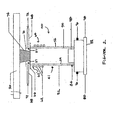
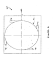
- Figure 1 illustrates an embodiment of the present plasma torch used with a deposition apparatus according to an embodiment of the present invention
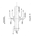
- Figure 2 illustrates cross-section side view of an embodiment of the present plasma torch depicting two ring disks according to an embodiment of the present invention
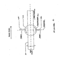
- Figure 3 illustrates a top plan view of another embodiment of the present plasma torch depicting a forward positioned nozzle according to an embodiment of the present invention
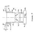
- Figure 4 illustrates a top plan view of another embodiment of the present plasma torch depicting a rearward positioned nozzle according to an embodiment of the present invention
- Figure 5 illustrates a cross-section side view of another embodiment of the present plasma torch depicting a concaved area of the middle quartz tube according to an embodiment of the present invention
- Figure 6 illustrates a top plan view of another embodiment of the present plasma torch depicting an arrangement of additional gas inlets according to an embodiment of the present invention.
- Figure 7 illustrates a cross-section comparison of the flow pattern between a prior art plasma torch and an embodiment of the present plasma torch according to an embodiment of the present invention.
- FIG. 1 shows an embodiment the present improved plasma torch for making synthetic glass with an exemplary apparatus 20 in accordance with the present invention.
- the apparatus comprises a hood 22, which provides proper exhaust to remove the gas by-products from the chemical reactions, and also provides RF isolation protection from the plasma torch such that the sealing prevents impurities from being introduced into the final product.
- a lathe 24 such as that available from Litton Engineering Lab.
- the lathe, 24 has a headstock 25 and a tailstock 26.
- the headstock 25 and the tailstock 26 are provided with a pair of opposing rotating spindle chucks 28 which hold the ends of an elongated target 30 having a substantially cylindrical outer wall.
- the spindle chucks 28 rotate target 30, as indicated by arrow A1.
- a movable carriage 32 movably mounted to the lathe 24 is arranged to travel in either direction along the target, as indicated by double headed arrow A2.
- the present induction plasma torch shown generally as 40, is supported by carriage 32.
- Carriage 32 thus moves induction plasma torch 40 along the length of the target 30.
- the spindle chucks 28 rotate the target 30 to ensure that material is uniformly deposited by the induction plasma torch 40 around the target so as to form a tubular member 34 having nearly perfectly cylindrical outer walls.
- the induction plasma torch 40 positioned on the carriage 32 moves in both directions along a substantial portion of the length of the target 30. This allows the induction plasma torch 40 to travel along this portion of the target 30 and deposit materials.
- the target 30 may be moved while the induction plasma torch 40 remains stationary. This can be realized by having the headstock 25 and the tailstock 26 of the lathe move the target in a reciprocating fashion so that all relevant portions of the target are brought directly above the induction plasma torch 40.
- a plurality of plasma sources may be spaced apart along the length of the target. This allows for reduced movement of either the headstock 25 or tailstock 26 of the lathe 24, or the carriage 32 to which the plasma sources are attached, depending on which of the two is configured to move. In the extreme case where a great number of plasma sources are provided all along the length of the target, no movement of either the carriage 32 or the headstock 25 and tailstock 26 of the lathe 24 is needed.
- the plasma torch 40 is an induction plasma torch having a dry plasma gas introduced into it through a first gas line 42 and a source gas introduced into it through a second gas line 44.
- the plasma gas is substantially comprised of nitrogen and oxygen in an appropriate, predetermined proportion. Air may serve as the plasma gas. In such case, air first passes through a first dryer 46 to remove moisture before entering the first gas line 42. This ensures that the hydroxyl concentration of the plasma gas is low, on the order of 1 ppm, or less.
- the source gas comprises at least the main source chemical such as SiCl 4 , with or without additional dopants and at least one carrier gas, such as oxygen or nitrogen.
- the carrier gases enter the second dryer 48 to remove moisture. This ensures that the - hydroxyl concentration of the source gas is also very low, on the order of 0.5 ppm
- the carrier gases proceed to a bubbler 50 or, as an alternative; a groups of bubblers could be used in place of bubbler 50 to pick up the source chemical.
- the gas stream comprising carrier gases laden with the source chemical then proceeds to the second gas line 44.
- a dopant gas may be introduced into the gas stream before it reaches the induction plasma torch.
- the source chemical is SiCl 4 .
- This chemical is chosen for its reactive properties in a plasma.
- the SiCl 4 serves as a source of Si to form SiO 2 , which is deposited on the target 30.
- the dopant for lowering the index of refraction is typically a fluorine dopant gas in the form of SiF 4 CF 4 or SF 6 . Fluorine dopants modify the index of refraction of the quartz and add a degree of freedom to the design of optical fiber preforms.
- the dopants for increasing the index refractions are typically in vapor form of GeCl 4 , POCl 3 , AlCl 3 , and TiCl 4 .
- FIG. 2 illustrates an embodiment of the present induction plasma torch 40 that includes two ring disks and three quartz tubes.
- the induction plasma torch 40 is positioned below the rotating target 30.
- the induction plasma torch 40 comprises a substantially tubular torch housing 41 formed from quartz.
- the housing 41 has an overall diameter of 100 mm and a height of 310 mm However, diameters ranging from 80 - 120 mm and heights between 180-400 mm may also be used.
- the middle quartz glass tube 54 is slightly taller than the outer quartz glass tube 52 and has two cut out openings or windows 57 opposite each other.
- the windows 57 have dimensions of 16 mm in height and 18 mm in width.
- the present induction plasma torch 40 also includes an inner quartz glass tube 58.
- the middle quartz glass tube 54 is preferably tallest when compared with both the inner quartz glass tube 58 and the outer quartz glass tube 52.
- the outer quartz glass tube 52 is preferably taller than the inner quartz glass tube 58.
- the typical dimensions of the quartz glass tubes are: inner quartz glass tube 58 has an outer diameter of approximately 60 mm and a length of approximately 150 mm; the middle quartz glass tube, 54 has an outer diameter of approximately 70 mm and a length of approximately 270 mm; and the outer quartz glass tube 52 has an outer diameter of approximately 85 mm and a length of approximately 200 mm.
- the present induction plasma torch 40 also includes a bottom quartz glass ring disk 66 and a top quartz glass ring disk 70.
- the bottom quartz glass ring disk 66 is welded substantially perpendicular onto the top of the outer quartz glass tube 52 above the coils 64 substantially perpendicular to the outer quartz glass tube 52 at its outer surface.
- the top quartz glass ring disk 70 is welded substantially perpendicular onto the top of the middle quartz glass tube 54.
- the dimensions of the quartz glass rings may be as follows: the bottom quartz glass ring disk 66 has an outer diameter of approximately 150 mm and an inner diameter of approximately 85 mm In addition, the top quartz glass ring disk 70 has an outer diameter of approximately 110 mm and an inner diameter of approximately 70 mm.
- the bottom quartz glass ring disk 66 and top quartz glass ring disk 70 define the flow pattern of the screen gas (described below). They force the screen gas to have a horizontal radial outward flow on the top of the present induction plasma torch 40. This flow creates a lower pressure region for the plasma gases, which will cause it to flow outward from the middle quartz glass tube 54. This will increase the width of the plasma flame 74. The wider flame will increase the width of the deposition zone on the lateral surface of the rotating target 30. This results in higher deposition rates and efficiencies of the process. Moreover, the stability of the plasma flame 74 can be maintained by adjusting the flow rate of the screen gas.
- bottom quartz glass ring disk 66 and top quartz glass ring disk 70 have solids support from the muddle quartz glass tube 54 and outer quartz glass tube 52 as compared to the stabilizer bars found in the prior art that have only one end attached to the quartz tubing. This new design increases the rigidity and decreases the repair and replacement costs of the present induction plasma torch 40.
- a pair of chemical injection ports 68 for injecting chemicals 72 are located vertically between the bottom quartz glass ring disk 66 and the top quartz glass ring disk 70, and they are located horizontally between the outer quartz glass tube 52 and middle quartz glass tube 54 and aimed toward the cut out windows 57 of middle quartz glass tube 54.
- the chemicals 72 for example SiCl 4
- the plasma flame 74 is introduced into the plasma flame 74 to produce silica soot particles that are deposited and consolidated on the rotating target 30.
- the pair of chemical injection ports 68 is connected to the second gas line 44 for carrying the source chemicals 72 to the induction plasma torch 40.
- the chemical injection ports 68 typically comprise quartz tubing having a diameter of 5 mm, although tubing diameters on the order of 3-10 mm may be used with the present induction plasma torch 40.
- the pair of chemical injection ports 68 is located relative to the housing at the same height and each of the chemical injection ports 68 of the pair are positioned diametrically across from each other. Instead of just two such chemical injection ports 68; however, three or even more chemical injection ports 68, symmetrically arranged, may be provided.
- a pair of plasma gas inlets 76 connects the first gas line 42 carrying the plasma gases to the induction plasma torch 40.
- the plasma gas inlets 76 enter the housing 41 at substantially the same height, proximate to the base of the housing 41.
- These plasma gas inlets 76 typically comprise stainless steel tubing having a diameter of 5 mm, although a range of diameters may suffice for this purpose.
- the induction plasma torch 40 is also preferably includes a coolant inlet 78 and outlet 80.
- a coolant such as water, passes through the inlet 78, circulates within the outer wall of the housing 41, and exits through the outlet 80.
- the coolant inlet and outlet are formed from stainless steel and have a diameter of 5 mm.
- the diameter of the coolant inlet 78 and outlet 80 may also vary to accommodate the desired thermodynamic properties of the induction plasma torch 40.
- the plasma gas inlets 76, the coolant inlet 78, and the coolant outlet 80 are all preferably formed in a stainless steel chamber 82.
- the chamber 82 is a stainless steel square block 100 mm on a side, and having a height of approximately 40 mm
- the chamber 82 is mounted onto the support stand 56, which in turn, is mounted on the carriage 32 for movement along the rotating target 30.
- the plasma gases are introduced tangentially through the plasma gas inlets 76 between the inner quartz glass tube 58 and middle quartz glass tube 54.
- a screen gas for example nitrogen, with a hydroxyl content of less than 1 ppm is introduced between the middle quartz glass tube 54 and the outer quartz glass tube 52 through screen, gas port 84.
- the dry screen gas flows between middle quartz glass tube 54 and the outer quartz glass tube 52 creating a nitrogen curtain, which prevents the moisture diffusion from the surrounding environment, thereby decreasing the hydroxyl content in the deposited quartz glass layers.
- the present induction plasma torch 40 is more effective in isolating the environmental influence and reducing the hydroxyl content than with passive stabilizer bars as found in the prior art.
- the induction plasma torch 40 further includes a copper induction coil 64 that is provide around the upper portion of its housing 41.
- the coil 64 comprises a plurality of windings 62 having a diameter of approximately 95 mm and spaced apart from each other by approximately 6 mm. A gap between the housing 41 and the coil can be between 2-10 mm.
- the uppermost portion of the coil 64, as indicated by uppermost winding 62', is separated from the bottom quartz glass ring disk 66 by a fixed distance of approximately 2 mm
- the induction coil 64 is located outside the outer quartz glass tube 52.
- a high frequency generator (not shown) is electrically connected to the coil 64, powering the coil 64 with a variable power output up to 60 kW at a frequency of 5.28+/-0.13 MHz.
- the generator is Model No. IG 60/5000, available from Fritz Huettinger Electronic GmbH of Germany. This generator is driven with a 50 Hz, 3-phase, 480 V power supply to energize the induction plasma torch 40.
- the present plasma torch 40 is mounted on a movable carriage 32, which is located on a glass-working lathe 24.
- the movable carriage 32 moves back and forth along the rotating target 30 during the deposition process. Due to the weight of the supporting equipment of the induction plasma torch 40, the preferred operation is to hold the carriage movable 32 stationary and move the rotating target 30.
- the target rod or tube will be moved from right to left and then back to its original position or as the forward and reverse motions indicate.
- Figure 3 illustrates another embodiment 120 of the present induction plasma torch having one or more off-center chemical injection nozzles, front chemical injection nozzle 122 and back chemical injection nozzle 124.
- prior art plasma torches included chemical injection ports that are positioned directly opposing each other.
- the back chemical nozzle 124 is inline with the centerline of the induction plasma torch 120, and the front chemical nozzle 122 is moved forward, same direction as the rotating target 30, about. 8 mm ahead of the back chemical torch 124.
- this arrangement and operated in the "forward direction” as shown in Figure 3 , an increase of deposition rate and the better control of the target diameter are achieved. This provides for a more uniform rotating target 30 diameter.
- an offset of 8 mm between the two nozzles provides improved deposition results. Additionally, this offsetting distance may be dependent upon several factors including: the size of the rotating target 30, the diameter of the induction plasma torch 120, the power generator being used, the plasma gas flow rate, and the raw chemicals used and also their feeding rate. Preferably, the offset can be in a range between 6 to 12 mm.
- the relative position for chemical injection nozzles 122 and 124 can be switched such that they are identical with respect to the direction of deposition.
- a switched arrangement of the front chemical injection nozzle 122 and the back chemical injection nozzle is shown with respect to the reverse movement of the rotating target 30.
- positions 1 and 2 of the nozzles are switched depending on the travel of either the rotating target 30 or the induction plasma torch 120.
- the front chemical injection nozzle 122 is lined up with the centerline of the induction plasma torch 120, while the back chemical injection nozzle 124 is ahead of the front chemical injection nozzle 122 by approximately 8mm
- the deposition In the forward direction as viewed by a person standing in front of the induction plasma torch 120, as shown in Figure 3 , the deposition is from the right end to the left end.
- the from chemical injection nozzle 122 is ahead of the induction plasma torch 120 centerline and the back chemical injection nozzle 124 is in-line with the induction plasma torch 120 centerline.
- the deposition In the reverse direction as viewed by a person standing in back of the induction plasma torch 120, as shows in Figure 4 , the deposition will be the right side moving to the left side.
- the back chemical injection nozzle 124 and the front chemical injection nozzle 122 are switched very quickly from one to the other, just before the beginning of the pass.
- the Position 1 is for forward motion and Position 2 is for reversed motion.
- the width of the opening windows 57 is changed to approximately 20 mm and the location of the windows 57 are no longer directly opposing each other. Instead there is an offset from each other. Enlarging the windows too much may cause excessive leakage of the plasma gases.
- the switching position of the chemical injection nozzles 122 and 124 can also be accomplished by using two additional nozzles at pre-established and fixed positions. Additionally, different valves and electronic controls to supply the chemicals to the desired nozzles may also achieve the same function.
- a build-up at the tip of the chemical injection nozzles 68, 122, and 124 occurs during the deposition process. These build-ups can gready reduce the deposition rate and the quality of the glass. Upon inspection, these build-ups are seen as barbs that are formed in the flow path of the chemical injection nozzles 68, 122, and 124.
- the ideal particle size is between 0.02 to 0.05 mm for the present process.
- the diameter of the deposited soot particles became very large, they became too difficult to consolidate. Very often, bubbles are also trapped in the glass with larger soot particles.
- the laminar flow is maintained at a fixed level for the chemical injection nozzles 68,122,124, the particle's size was uniformly reduced, which improved the quality of the glass. Moreover, it also minimized the possible build up of soot particles at the tip of the chemical injection nozzles 68, 122,124 and it reduced the need and frequency of maintenance.
- FIG. 5 illustrates another embodiment 150 of the present induction plasma torch of the present invention.
- the induction plasma torch 150 includes a middle quartz glass tube 154 that has a concave section 152.
- a concave section 152 is manufactured right above the top of the inner quartz glass tube 58.
- This concave section 152 gradually reduces the diameter to about 30% of its overall diameter and then curves back out to the normal diameter.
- the concave section 152 begins at approximately 3 mm above the top of the inner quartz glass tube 58.
- the total vertical length of the concave section is approximately 30mm and the smallest diameter of the concave is approximately 50 mm.
- the inner quartz glass tube 58 has an outer diameter of approximately 60 mm and a length of approximately 150 mm; the middle quartz glass tube 154 has an outer diameter of approximately 70 mm and a length of approximately 255 mm; and the outer quartz glass tube 52 has an outer diameter of approximately 85 mm and a length of approximately 200 mm.
- the advantages of the present induction plasma torch 150 is an increase in the efficiency of the induction plasma torch 150 and improved average plasma jet enthalpy.
- the swirl flow pattern used in the present induction plasma torch 150 has a very unique character.
- the intense flow rotation results in formation of a recirculation zone.
- the reverse flow on the axis of the zone results in formation of a plasma "tail" that extends upstream of the inductor region (in the present embodiment below the coil).
- the length of this zone in the cold gas region can be many times larger than the tube diameter, thus it can reach to the vicinity of the plasma gas inlets 76.
- FIG. 6 illustrates a top plan view of another embodiment 200 of the present plasma torch depicting an arrangement of additional gas inlets according to an embodiment of the present invention.
- four separate plasma gas inlets 76 are oriented tangentially about the chamber 82. As discussed above, these plasma gas inlets 76 connect the first gas line carrying the plasma gases to the induction plasma torch 40. These plasma gas inlets 76 may be the same dimensions and made of the same materials as described above. The number and orientation of these plasma gas inlets 76 produce a circular or swirl pattern of the plasma gas and improved plasma flame 74. Any number of plasma gas inlets 76 may be used to achieve the desired flow pattern of the plasma gas.
- SL Skin Layer
- RZ Plasma Recirculation Zone
- SM Streamlines.
- the concave section 152 may be used with additional plasma gas inlets 76.
- the flow rate can be reduced to each individual plasma gas inlet 76, while maintaining the designed total flow rate. This improves the rotational symmetry 126 (as shown in Figures 3 and 4 ) of the plasma flame or jet 74. This will also improve the stabilization of plasma flame or jet 74.
- four plasma gas inlets 76 are used.
- the opposing two plasma gas inlets 76 may supply the main plasma gas, and the other two plasma gas inlets 76 maybe used as auxiliary.
- These four plasma gas inlets 76 do not need to be on the same plane and, as a result, - controlling the location and the plane of the four plasma gas inlets 76 can create different kinds of flow patterns. Additionally, adjusting the individual gas flow to each plasma gas inlet 76 can create different kinds of flow patterns. Additional plasma gas inlets 76 may be used to supply gas phase raw materials such as Fluorine containing gas (e.g. SiF 4 , CF 4 or SF 6 ). It is also possible to use them to supply vapor phase components of raw materials when we do not want the premixing to occur before entering the reaction zone.
- gas phase raw materials such as Fluorine containing gas (e.g. SiF 4 , CF 4 or SF 6 ). It is also possible to use them to supply vapor phase components of raw materials when we do not want the premixing to occur before entering the reaction zone.
- the angular inclination to which the chemical injection ports 68 are aimed downward depends on the diameter of the induction plasma torch 150, the dimensions of the concave section 152, the flow rate of plasma gas, the coupled plasma energy, and the chemical reactant raw materials.
- the extension of the middle quartz glass tube 54 above the outer quartz glass tube 52 as shown in Figure 2 can be eliminated.
- the windows 57 for the chemical injection can also be eliminated.
- the top and bottom rings become much closer. It is also possible to eliminate the top quartz glass ring disk 70 because the bottom quartz glass ring disk 66 is adequate to form the desired air curtain.
- the bottom quartz glass ring disk 66 will be able to form the screen gas with a horizontal radial outward flow direction. This is because the bottom quartz glass ring disk 66 by itself can provide the necessary environmental shield. For this embodiment, the removal of the top quartz glass ring disk 70 will save the equipment manufacture cost, simplify the design, and make the induction plasma torch 150 more compact.
- the enthalpy of the plasma flame 74 is increased without requiring an increase of the power from the generator. This provides for increased productivity without using a larger power supply. Moreover, the process efficiency was also increase by approximately 10% and, as well, the process also greatly reduced bubble formation in the deposited glass.
- the present induction plasma torches 40, 120, 150, and 200 may be operated in a horizontal mode to deposit silica for making preforms, tubes, rods, or all three.
- the present induction plasma torches, 40, 120, 150, and 200 may be used to deposit silica glass in a vertical mode fashion that will allow us to make glass blanks or ingots.
- a manufacturing example will show the real advantage of these improvements.
- the other advantage of the present design is shown from the consideration from the raw material usage.
- the induction plasma torch of this invention results in a 40% savings in material costs.
Landscapes
- Engineering & Computer Science (AREA)
- Physics & Mathematics (AREA)
- Plasma & Fusion (AREA)
- Chemical & Material Sciences (AREA)
- Spectroscopy & Molecular Physics (AREA)
- Life Sciences & Earth Sciences (AREA)
- Materials Engineering (AREA)
- General Chemical & Material Sciences (AREA)
- Electromagnetism (AREA)
- General Life Sciences & Earth Sciences (AREA)
- Geochemistry & Mineralogy (AREA)
- Manufacturing & Machinery (AREA)
- Chemical Kinetics & Catalysis (AREA)
- Organic Chemistry (AREA)
- Manufacture, Treatment Of Glass Fibers (AREA)
- Plasma Technology (AREA)
- Silicon Compounds (AREA)
- Glass Melting And Manufacturing (AREA)
- Chemical Vapour Deposition (AREA)
Claims (16)
- Torche à plasma pour réaliser de la silice synthétique comprenant :un tube de verre de quartz externe (52) d'une première longueur et d'un premier diamètre en coupe transversale et ayant une première extrémité connectée à une base et une seconde extrémité orientée vers un substrat (30), ledit tube de verre de quartz externe (52) étant encerclé par une bobine d'induction (64) ;un tube de verre de quartz interne (58) d'une deuxième longueur et d'un deuxième diamètre en coupe transversale et ayant une première extrémité connectée à ladite base et une seconde extrémité orientée vers ledit substrat, ledit deuxième diamètre en coupe transversale étant inférieur audit premier diamètre en coupe transversale de telle sorte que ledit tube de verre de quartz interne soit disposé sensiblement parallèlement audit tube de verre de quartz externe et à l'intérieur de celui-ci ;un tube de verre de quartz intermédiaire (54) d'une troisième longueur et d'un troisième diamètre en coupe transversale et ayant une première extrémité connectée à ladite base et une seconde extrémité orientée vers ledit substrat, ladite seconde extrémité dudit tube de verre de quartz intermédiaire (54) s'étendant au-delà de ladite seconde extrémité dudit tube de verre de quartz externe (52), ledit troisième diamètre en coupe transversale étant inférieur audit premier diamètre en coupe transversale et supérieur audit deuxième diamètre en coupe transversale de telle sorte que ledit tube de verre de quartz intermédiaire (54) soit disposé sensiblement parallèlement audit tube de verre de quartz externe (52) et audit tube de verre de quartz interne (52) et entre ceux-ci pour constituer un passage entre ledit tube de verre de quartz intermédiaire (54) et ledit tube de verre de quartz externe (52) pour un gaz écran, et pour constituer un passage entre ledit tube de verre de quartz interne (58) et ledit tube de verre de quartz intermédiaire (54) pour un gaz plasma afin de produire un jet de plasma (74) quand ladite bobine d'induction (64) est excitée ;un premier disque annulaire de verre de quartz (66) connecté sur le côté extérieur de ladite seconde extrémité dudit tube de verre de quartz externe (52) ;un second disque annulaire de verre de quartz (70) connecté sur le côté extérieur de la seconde extrémité dudit tube de verre de quartz intermédiaire (54), la configuration d'écoulement dudit gaz écran étant déterminée par ledit premier disque annulaire de verre de quartz (66) et ledit second disque annulaire de verre de quartz (70) ; etau moins une buse d'injection chimique (68) disposée entre ledit premier disque annulaire de verre de quartz (66) et ledit second disque annulaire de verre de quartz (70) pour injecter un gaz de source chimique (72) dans ledit jet de plasma (74).
- Torche à plasma pour réaliser de la silice synthétique selon la revendication 1, dans laquelle ladite seconde extrémité dudit tube de verre de quartz externe (52) s'étend au-delà de ladite seconde extrémité dudit tube de verre de quartz interne (58).
- Torche à plasma pour réaliser de la silice synthétique selon la revendication 1, dans laquelle lesdits premier et second disques annulaires de verre de quartz (66, 70) sont sensiblement perpendiculaires audit tube de verre de quartz intermédiaire (54).
- Torche à plasma pour réaliser de la silice synthétique selon la revendication 1, dans laquelle ledit tube de verre de quartz intermédiaire (54) comprend en outre :au moins une ouverture (57) aménagée sensiblement près de ladite seconde extrémité dudit tube de verre de quartz intermédiaire (54) pour constituer un passage pour ledit gaz de source chimique injecté (72) dans ledit jet de plasma (74).
- Torche à plasma pour réaliser de la silice synthétique selon la revendication 4, dans laquelle ladite au moins une ouverture (57) est aménagée verticalement entre lesdits premier et second disques annulaires de verre de quartz (66, 70).
- Torche à plasma pour réaliser de la silice synthétique selon la revendication 1, dans laquelle lesdits premier, deuxième et troisième diamètres en coupe transversale sont mutuellement concentriques.
- Torche à plasma pour réaliser de la silice synthétique selon la revendication 1, dans laquelle ladite bobine (64) est disposée verticalement entre ledit premier disque annulaire de verre de quartz (66) et ladite base (82).
- Torche à plasma pour réaliser de la silice synthétique selon la revendication 1, dans laquelle lesdits premier et second disques annulaires de verre de quartz (66, 70) sont positionnés pour réduire la région de pression du gaz plasma afin d'amener ledit gaz écran à prendre une configuration d'écoulement radial horizontal près du jet de plasma (74).
- Torche à plasma pour réaliser de la silice synthétique selon la revendication 1, dans laquelle ladite au moins une buse d'injection chimique comprend :une première buse d'injection chimique (124) située dans l'axe central de ladite torche à plasma ; etune seconde buse d'injection chimique (122) située en avant dudit axe central de ladite torche à plasma.
- Torche à plasma pour réaliser de la silice synthétique selon la revendication 1, dans laquelle ledit tube de verre de quartz intermédiaire (54) comporte une restriction concave formée (512) autour de son périmètre au-dessus dudit tube de verre de quartz interne (58).
- Torche à plasma pour réaliser de la silice synthétique selon la revendication 1, dans laquelle ladite au moins une buse d'injection chimique (68) est inclinée vers le bas depuis un plan horizontal.
- Appareil de dépôt par plasma pour réaliser de la silice synthétique comprenant :une torche à plasma comprenant :un tube de verre de quartz externe (52) ayant une extrémité sensiblement perpendiculaire à un substrat (30), ledit tube de verre de quartz externe étant encerclé par une bobine d'induction (64) ;un tube de verre de quartz interne (58) ayant une extrémité sensiblement perpendiculaire audit substrat ;un tube de verre de quartz intermédiaire (54) ayant une extrémité sensiblement perpendiculaire audit substrat, ledit tube de verre de quartz intermédiaire (54) étant situé entre ledit tube de verre de quartz externe (52) et ledit tube de verre de quartz interne (58), ladite une extrémité dudit tube de verre de quartz intermédiaire (54) s'étendant au-delà de ladite une extrémité dudit tube de verre de quartz externe (52), lesdits tubes étant concentriques pour constituer un premier passage entre ledit tube de verre de quartz interne (58) et ledit tube de verre de quartz intermédiaire (54) pour un gaz plasma afin de produire un jet de plasma (74) quand ladite bobine d'induction (64) est excitée et un second passage entre ledit tube de verre de quartz externe (52) et ledit tube de verre de quartz intermédiaire (54) pour un gaz écran ;un premier disque annulaire de verre de quartz (66) connecté sur le côté extérieur de ladite une extrémité dudit tube de verre de quartz externe (52) ;un second disque annulaire de verre de quartz (70) connecté sur le côté extérieur de ladite une extrémité dudit tube de verre de quartz intermédiaire (54), la configuration d'écoulement dudit gaz écran étant déterminée par ledit premier disque annulaire de verre de quartz (66) et ledit second disque annulaire de verre de quartz (70) ;au moins une buse d'injection chimique (68) disposée entre ledit premier disque annulaire de verre de quartz (66) et ledit second disque annulaire de verre de quartz (70) pour injecter un gaz de source chimique (72) dans ledit jet de plasma (74) ; etun moyen de support dudit substrat (30), ledit substrat et ledit moyen de support se déplaçant relativement l'un à l'autre.
- Appareil de dépôt par plasma pour réaliser de la silice synthétique selon la revendication 12, dans lequel lesdits premier et second disques annulaires de verre de quartz (66, 70) sont positionnés pour réduire la région de pression du gaz plasma afin d'amener ledit gaz écran à prendre une configuration d'écoulement radial horizontal près sujet de plasma (74).
- Appareil de dépôt par plasma pour réaliser de la silice synthétique selon la revendication 12, dans lequel ladite au moins une buse d'injection chimique comprend :une première buse d'injection chimique (124) située dans l'axe central de ladite torche à plasma ;une seconde buse d'injection chimique (122) située en avant dudit axe central de ladite torche à plasma (120).
- Appareil de dépôt par plasma pour réaliser de la silice synthétique selon la revendication 14, dans laquelle ladite torche à plasma (120) tourne axialement par rapport audit substrat pour présenter ladite seconde buse d'injection chimique comme buse d'injection chimique frontale durant ledit mouvement dudit substrat (30) par rapport à ladite torche à plasma (120).
- Appareil de dépôt par plasma pour réaliser de la silice synthétique selon la revendication 12, dans lequel ladite au moins une buse d'injection chimique (68) est inclinée vers le bas depuis un plan horizontal.
Applications Claiming Priority (3)
| Application Number | Priority Date | Filing Date | Title |
|---|---|---|---|
| US75428105P | 2005-12-29 | 2005-12-29 | |
| PCT/US2006/049389 WO2007079127A2 (fr) | 2005-12-29 | 2006-12-28 | Chalumeau a plasma ameliore pour la fabrication de silice synthetique |
| US11/646,362 US7861557B2 (en) | 2005-12-29 | 2006-12-28 | Plasma torch for making synthetic silica |
Publications (2)
| Publication Number | Publication Date |
|---|---|
| EP1968907A2 EP1968907A2 (fr) | 2008-09-17 |
| EP1968907B1 true EP1968907B1 (fr) | 2011-07-27 |
Family
ID=38137341
Family Applications (1)
| Application Number | Title | Priority Date | Filing Date |
|---|---|---|---|
| EP06848223A Not-in-force EP1968907B1 (fr) | 2005-12-29 | 2006-12-28 | Chalumeau a plasma pour la fabrication de silice synthetique |
Country Status (9)
| Country | Link |
|---|---|
| US (1) | US7861557B2 (fr) |
| EP (1) | EP1968907B1 (fr) |
| JP (1) | JP2009522199A (fr) |
| CN (1) | CN101389573B (fr) |
| AT (1) | ATE517850T1 (fr) |
| BR (1) | BRPI0620801A2 (fr) |
| CA (1) | CA2635645A1 (fr) |
| RU (1) | RU2391298C2 (fr) |
| WO (1) | WO2007079127A2 (fr) |
Families Citing this family (14)
| Publication number | Priority date | Publication date | Assignee | Title |
|---|---|---|---|---|
| DE102009010497A1 (de) * | 2008-12-19 | 2010-08-05 | J-Fiber Gmbh | Mehrdüsiger rohrförmiger Plasma-Abscheidebrenner zur Herstellung von Vorformen als Halbzeuge für optische Fasern |
| DE202008017383U1 (de) | 2008-12-19 | 2009-08-20 | J-Fiber Gmbh | Glas, insbesondere Glasfaser-Preform |
| DE102010050082B4 (de) * | 2010-09-15 | 2017-04-27 | J-Plasma Gmbh | Brenner |
| RU2542952C2 (ru) * | 2013-04-15 | 2015-02-27 | Открытое акционерное общество "Ракетно-космическая корпорация "Энергия" имени С.П. Королева" | Коммутатор напряжения с защитой от перегрузки по току |
| CN105271701B (zh) * | 2015-11-16 | 2017-08-29 | 江苏通鼎光棒有限公司 | 一种在ovd沉积过程中保护喷灯导轨的装置及方法 |
| US10773990B2 (en) * | 2016-10-21 | 2020-09-15 | Corning Incorporated | Purge device for an optical fiber draw system |
| WO2019238808A1 (fr) | 2018-06-15 | 2019-12-19 | Solar Silicon Gmbh | Procédé de production de silicium élémentaire |
| JP7332169B2 (ja) * | 2018-11-02 | 2023-08-23 | 学校法人日本大学 | 磁化プラズモイド射出装置 |
| CN111843139A (zh) * | 2019-04-26 | 2020-10-30 | 中天科技精密材料有限公司 | 等离子喷灯及其应用方法 |
| CN113548796B (zh) * | 2019-07-15 | 2022-11-04 | 富通集团(嘉善)通信技术有限公司 | 一种光纤预制棒的沉积设备 |
| CN112441736B (zh) * | 2019-08-30 | 2023-10-03 | 中天科技精密材料有限公司 | 光纤预制棒及其制备方法、等离子沉积设备 |
| JP7428632B2 (ja) | 2020-12-14 | 2024-02-06 | 信越化学工業株式会社 | 多孔質ガラス母材の製造方法及び製造装置 |
| CN112479216A (zh) * | 2021-01-24 | 2021-03-12 | 刘冠诚 | 一种节能环保纳米二氧化硅生产装置及工艺 |
| CN117682751A (zh) * | 2023-11-23 | 2024-03-12 | 中建材玻璃新材料研究院集团有限公司 | 一种高纯石英玻璃的制备方法 |
Family Cites Families (12)
| Publication number | Priority date | Publication date | Assignee | Title |
|---|---|---|---|---|
| US4162908A (en) * | 1975-08-16 | 1979-07-31 | Heraeus Quarzschmelze Gmbh | Method of producing synthetic quartz glass, apparatus for the practice of the method, and use of the synthetic quartz glass |
| US4440558A (en) * | 1982-06-14 | 1984-04-03 | International Telephone And Telegraph Corporation | Fabrication of optical preforms by axial chemical vapor deposition |
| JP2505489B2 (ja) * | 1987-09-18 | 1996-06-12 | 三菱重工業株式会社 | プラズマト―チ放射光の減光方法 |
| JPH0189872U (fr) * | 1987-12-09 | 1989-06-13 | ||
| JP2908912B2 (ja) * | 1991-08-30 | 1999-06-23 | 日本電子株式会社 | 誘導プラズマ発生装置におけるプラズマ着火方法 |
| US5420391B1 (en) * | 1994-06-20 | 1998-06-09 | Metcon Services Ltd | Plasma torch with axial injection of feedstock |
| US6253580B1 (en) * | 1997-12-19 | 2001-07-03 | Fibercore, Inc. | Method of making a tubular member for optical fiber production using plasma outside vapor deposition |
| CN1295169C (zh) * | 1998-04-10 | 2007-01-17 | 纤维管有限公司 | 制造光纤预型件的方法 |
| US6536240B1 (en) * | 1998-04-10 | 2003-03-25 | Mikhail Ivanovich Gouskov | Method of making an optical fiber preform via multiple plasma depositing and sintering steps |
| US6215092B1 (en) * | 1999-06-08 | 2001-04-10 | Alcatel | Plasma overcladding process and apparatus having multiple plasma torches |
| EP1213950A2 (fr) * | 2000-12-06 | 2002-06-12 | Alcatel | Torche à plasma modifiée pour délivrer une enthalpie accrue |
| JP2003194723A (ja) * | 2001-12-27 | 2003-07-09 | Rikogaku Shinkokai | プラズマトーチ |
-
2006
- 2006-12-28 CA CA002635645A patent/CA2635645A1/fr not_active Abandoned
- 2006-12-28 AT AT06848223T patent/ATE517850T1/de not_active IP Right Cessation
- 2006-12-28 CN CN2006800534981A patent/CN101389573B/zh not_active Expired - Fee Related
- 2006-12-28 WO PCT/US2006/049389 patent/WO2007079127A2/fr active Application Filing
- 2006-12-28 US US11/646,362 patent/US7861557B2/en not_active Expired - Fee Related
- 2006-12-28 RU RU2008131073/03A patent/RU2391298C2/ru not_active IP Right Cessation
- 2006-12-28 EP EP06848223A patent/EP1968907B1/fr not_active Not-in-force
- 2006-12-28 JP JP2008548710A patent/JP2009522199A/ja not_active Ceased
- 2006-12-28 BR BRPI0620801-0A patent/BRPI0620801A2/pt not_active IP Right Cessation
Also Published As
| Publication number | Publication date |
|---|---|
| WO2007079127B1 (fr) | 2007-11-01 |
| CN101389573A (zh) | 2009-03-18 |
| ATE517850T1 (de) | 2011-08-15 |
| WO2007079127A2 (fr) | 2007-07-12 |
| CN101389573B (zh) | 2011-11-16 |
| BRPI0620801A2 (pt) | 2012-06-05 |
| WO2007079127A3 (fr) | 2007-09-07 |
| RU2391298C2 (ru) | 2010-06-10 |
| RU2008131073A (ru) | 2010-02-10 |
| US7861557B2 (en) | 2011-01-04 |
| CA2635645A1 (fr) | 2007-07-12 |
| JP2009522199A (ja) | 2009-06-11 |
| EP1968907A2 (fr) | 2008-09-17 |
| US20070169516A1 (en) | 2007-07-26 |
Similar Documents
| Publication | Publication Date | Title |
|---|---|---|
| EP1968907B1 (fr) | Chalumeau a plasma pour la fabrication de silice synthetique | |
| US6253580B1 (en) | Method of making a tubular member for optical fiber production using plasma outside vapor deposition | |
| EP0656326B1 (fr) | Procédé de fabrication d'une optique à partir d'une préforme | |
| EP2583952B1 (fr) | Procédé et brûleur pour la fabrication d'une préforme en verre poreux | |
| US8192807B2 (en) | Ring plasma jet method and apparatus for making an optical fiber preform | |
| AU750390B2 (en) | Method of making an optical fiber preform | |
| RU2551587C2 (ru) | Многофорсуночная плазменная трубообразная горелка-осадитель для производства заготовок как полуфабрикатов для изготовления оптических волокон | |
| EP2573054B1 (fr) | Procédé de fabrication d'une préforme pour fibre optiques par l'hydrolyse dans la flamme | |
| EP2221281B1 (fr) | Brûleur pour la fabrication de matériau de base en verre poreux, et procédé de fabrication de matériau à base de verre poreux | |
| EP2098488B1 (fr) | Procédé de fabrication de préforme de fibre optique | |
| WO2001017918A1 (fr) | Appareil de fabrication de preforme de verre par hydrolyse a la flamme | |
| GB2351287A (en) | Making optical fibre preforms using plasma outside vapour deposition | |
| JP2005146368A (ja) | プラズマ発生装置及びガラス加工方法 |
Legal Events
| Date | Code | Title | Description |
|---|---|---|---|
| PUAI | Public reference made under article 153(3) epc to a published international application that has entered the european phase |
Free format text: ORIGINAL CODE: 0009012 |
|
| 17P | Request for examination filed |
Effective date: 20080716 |
|
| AK | Designated contracting states |
Kind code of ref document: A2 Designated state(s): AT BE BG CH CY CZ DE DK EE ES FI FR GB GR HU IE IS IT LI LT LU LV MC NL PL PT RO SE SI SK TR |
|
| 17Q | First examination report despatched |
Effective date: 20090204 |
|
| GRAP | Despatch of communication of intention to grant a patent |
Free format text: ORIGINAL CODE: EPIDOSNIGR1 |
|
| DAX | Request for extension of the european patent (deleted) | ||
| GRAS | Grant fee paid |
Free format text: ORIGINAL CODE: EPIDOSNIGR3 |
|
| GRAA | (expected) grant |
Free format text: ORIGINAL CODE: 0009210 |
|
| AK | Designated contracting states |
Kind code of ref document: B1 Designated state(s): AT BE BG CH CY CZ DE DK EE ES FI FR GB GR HU IE IS IT LI LT LU LV MC NL PL PT RO SE SI SK TR |
|
| REG | Reference to a national code |
Ref country code: GB Ref legal event code: FG4D |
|
| REG | Reference to a national code |
Ref country code: CH Ref legal event code: EP |
|
| REG | Reference to a national code |
Ref country code: DE Ref legal event code: R096 Ref document number: 602006023442 Country of ref document: DE Effective date: 20110915 |
|
| REG | Reference to a national code |
Ref country code: NL Ref legal event code: VDEP Effective date: 20110727 |
|
| REG | Reference to a national code |
Ref country code: AT Ref legal event code: MK05 Ref document number: 517850 Country of ref document: AT Kind code of ref document: T Effective date: 20110727 |
|
| PG25 | Lapsed in a contracting state [announced via postgrant information from national office to epo] |
Ref country code: PT Free format text: LAPSE BECAUSE OF FAILURE TO SUBMIT A TRANSLATION OF THE DESCRIPTION OR TO PAY THE FEE WITHIN THE PRESCRIBED TIME-LIMIT Effective date: 20111128 Ref country code: BE Free format text: LAPSE BECAUSE OF FAILURE TO SUBMIT A TRANSLATION OF THE DESCRIPTION OR TO PAY THE FEE WITHIN THE PRESCRIBED TIME-LIMIT Effective date: 20110727 Ref country code: IS Free format text: LAPSE BECAUSE OF FAILURE TO SUBMIT A TRANSLATION OF THE DESCRIPTION OR TO PAY THE FEE WITHIN THE PRESCRIBED TIME-LIMIT Effective date: 20111127 Ref country code: FI Free format text: LAPSE BECAUSE OF FAILURE TO SUBMIT A TRANSLATION OF THE DESCRIPTION OR TO PAY THE FEE WITHIN THE PRESCRIBED TIME-LIMIT Effective date: 20110727 Ref country code: SE Free format text: LAPSE BECAUSE OF FAILURE TO SUBMIT A TRANSLATION OF THE DESCRIPTION OR TO PAY THE FEE WITHIN THE PRESCRIBED TIME-LIMIT Effective date: 20110727 Ref country code: NL Free format text: LAPSE BECAUSE OF FAILURE TO SUBMIT A TRANSLATION OF THE DESCRIPTION OR TO PAY THE FEE WITHIN THE PRESCRIBED TIME-LIMIT Effective date: 20110727 Ref country code: LT Free format text: LAPSE BECAUSE OF FAILURE TO SUBMIT A TRANSLATION OF THE DESCRIPTION OR TO PAY THE FEE WITHIN THE PRESCRIBED TIME-LIMIT Effective date: 20110727 |
|
| PG25 | Lapsed in a contracting state [announced via postgrant information from national office to epo] |
Ref country code: AT Free format text: LAPSE BECAUSE OF FAILURE TO SUBMIT A TRANSLATION OF THE DESCRIPTION OR TO PAY THE FEE WITHIN THE PRESCRIBED TIME-LIMIT Effective date: 20110727 Ref country code: PL Free format text: LAPSE BECAUSE OF FAILURE TO SUBMIT A TRANSLATION OF THE DESCRIPTION OR TO PAY THE FEE WITHIN THE PRESCRIBED TIME-LIMIT Effective date: 20110727 Ref country code: GR Free format text: LAPSE BECAUSE OF FAILURE TO SUBMIT A TRANSLATION OF THE DESCRIPTION OR TO PAY THE FEE WITHIN THE PRESCRIBED TIME-LIMIT Effective date: 20111028 Ref country code: LV Free format text: LAPSE BECAUSE OF FAILURE TO SUBMIT A TRANSLATION OF THE DESCRIPTION OR TO PAY THE FEE WITHIN THE PRESCRIBED TIME-LIMIT Effective date: 20110727 Ref country code: SI Free format text: LAPSE BECAUSE OF FAILURE TO SUBMIT A TRANSLATION OF THE DESCRIPTION OR TO PAY THE FEE WITHIN THE PRESCRIBED TIME-LIMIT Effective date: 20110727 Ref country code: CY Free format text: LAPSE BECAUSE OF FAILURE TO SUBMIT A TRANSLATION OF THE DESCRIPTION OR TO PAY THE FEE WITHIN THE PRESCRIBED TIME-LIMIT Effective date: 20110727 |
|
| PG25 | Lapsed in a contracting state [announced via postgrant information from national office to epo] |
Ref country code: CZ Free format text: LAPSE BECAUSE OF FAILURE TO SUBMIT A TRANSLATION OF THE DESCRIPTION OR TO PAY THE FEE WITHIN THE PRESCRIBED TIME-LIMIT Effective date: 20110727 Ref country code: SK Free format text: LAPSE BECAUSE OF FAILURE TO SUBMIT A TRANSLATION OF THE DESCRIPTION OR TO PAY THE FEE WITHIN THE PRESCRIBED TIME-LIMIT Effective date: 20110727 |
|
| PG25 | Lapsed in a contracting state [announced via postgrant information from national office to epo] |
Ref country code: RO Free format text: LAPSE BECAUSE OF FAILURE TO SUBMIT A TRANSLATION OF THE DESCRIPTION OR TO PAY THE FEE WITHIN THE PRESCRIBED TIME-LIMIT Effective date: 20110727 Ref country code: IT Free format text: LAPSE BECAUSE OF FAILURE TO SUBMIT A TRANSLATION OF THE DESCRIPTION OR TO PAY THE FEE WITHIN THE PRESCRIBED TIME-LIMIT Effective date: 20110727 Ref country code: EE Free format text: LAPSE BECAUSE OF FAILURE TO SUBMIT A TRANSLATION OF THE DESCRIPTION OR TO PAY THE FEE WITHIN THE PRESCRIBED TIME-LIMIT Effective date: 20110727 |
|
| PLBE | No opposition filed within time limit |
Free format text: ORIGINAL CODE: 0009261 |
|
| STAA | Information on the status of an ep patent application or granted ep patent |
Free format text: STATUS: NO OPPOSITION FILED WITHIN TIME LIMIT |
|
| PG25 | Lapsed in a contracting state [announced via postgrant information from national office to epo] |
Ref country code: DK Free format text: LAPSE BECAUSE OF FAILURE TO SUBMIT A TRANSLATION OF THE DESCRIPTION OR TO PAY THE FEE WITHIN THE PRESCRIBED TIME-LIMIT Effective date: 20110727 |
|
| 26N | No opposition filed |
Effective date: 20120502 |
|
| PG25 | Lapsed in a contracting state [announced via postgrant information from national office to epo] |
Ref country code: MC Free format text: LAPSE BECAUSE OF NON-PAYMENT OF DUE FEES Effective date: 20111231 |
|
| REG | Reference to a national code |
Ref country code: CH Ref legal event code: PL |
|
| REG | Reference to a national code |
Ref country code: DE Ref legal event code: R097 Ref document number: 602006023442 Country of ref document: DE Effective date: 20120502 |
|
| GBPC | Gb: european patent ceased through non-payment of renewal fee |
Effective date: 20111228 |
|
| REG | Reference to a national code |
Ref country code: FR Ref legal event code: ST Effective date: 20120831 |
|
| REG | Reference to a national code |
Ref country code: IE Ref legal event code: MM4A |
|
| PG25 | Lapsed in a contracting state [announced via postgrant information from national office to epo] |
Ref country code: GB Free format text: LAPSE BECAUSE OF NON-PAYMENT OF DUE FEES Effective date: 20111228 Ref country code: LI Free format text: LAPSE BECAUSE OF NON-PAYMENT OF DUE FEES Effective date: 20111231 Ref country code: CH Free format text: LAPSE BECAUSE OF NON-PAYMENT OF DUE FEES Effective date: 20111231 Ref country code: IE Free format text: LAPSE BECAUSE OF NON-PAYMENT OF DUE FEES Effective date: 20111228 |
|
| PG25 | Lapsed in a contracting state [announced via postgrant information from national office to epo] |
Ref country code: FR Free format text: LAPSE BECAUSE OF NON-PAYMENT OF DUE FEES Effective date: 20120102 Ref country code: ES Free format text: LAPSE BECAUSE OF FAILURE TO SUBMIT A TRANSLATION OF THE DESCRIPTION OR TO PAY THE FEE WITHIN THE PRESCRIBED TIME-LIMIT Effective date: 20111107 |
|
| PG25 | Lapsed in a contracting state [announced via postgrant information from national office to epo] |
Ref country code: LU Free format text: LAPSE BECAUSE OF NON-PAYMENT OF DUE FEES Effective date: 20111228 |
|
| PG25 | Lapsed in a contracting state [announced via postgrant information from national office to epo] |
Ref country code: BG Free format text: LAPSE BECAUSE OF FAILURE TO SUBMIT A TRANSLATION OF THE DESCRIPTION OR TO PAY THE FEE WITHIN THE PRESCRIBED TIME-LIMIT Effective date: 20111027 |
|
| PGFP | Annual fee paid to national office [announced via postgrant information from national office to epo] |
Ref country code: DE Payment date: 20130628 Year of fee payment: 7 |
|
| PG25 | Lapsed in a contracting state [announced via postgrant information from national office to epo] |
Ref country code: TR Free format text: LAPSE BECAUSE OF FAILURE TO SUBMIT A TRANSLATION OF THE DESCRIPTION OR TO PAY THE FEE WITHIN THE PRESCRIBED TIME-LIMIT Effective date: 20110727 |
|
| PG25 | Lapsed in a contracting state [announced via postgrant information from national office to epo] |
Ref country code: HU Free format text: LAPSE BECAUSE OF FAILURE TO SUBMIT A TRANSLATION OF THE DESCRIPTION OR TO PAY THE FEE WITHIN THE PRESCRIBED TIME-LIMIT Effective date: 20110727 |
|
| REG | Reference to a national code |
Ref country code: DE Ref legal event code: R119 Ref document number: 602006023442 Country of ref document: DE |
|
| REG | Reference to a national code |
Ref country code: DE Ref legal event code: R119 Ref document number: 602006023442 Country of ref document: DE Effective date: 20140701 |
|
| PG25 | Lapsed in a contracting state [announced via postgrant information from national office to epo] |
Ref country code: DE Free format text: LAPSE BECAUSE OF NON-PAYMENT OF DUE FEES Effective date: 20140701 |