EP1968203A2 - HF-Kommunikationssystem mit mehreren Betriebsarten - Google Patents
HF-Kommunikationssystem mit mehreren Betriebsarten Download PDFInfo
- Publication number
- EP1968203A2 EP1968203A2 EP08151887A EP08151887A EP1968203A2 EP 1968203 A2 EP1968203 A2 EP 1968203A2 EP 08151887 A EP08151887 A EP 08151887A EP 08151887 A EP08151887 A EP 08151887A EP 1968203 A2 EP1968203 A2 EP 1968203A2
- Authority
- EP
- European Patent Office
- Prior art keywords
- transceiver
- signals
- transmitting
- coupled
- antenna
- Prior art date
- Legal status (The legal status is an assumption and is not a legal conclusion. Google has not performed a legal analysis and makes no representation as to the accuracy of the status listed.)
- Withdrawn
Links
- 230000005236 sound signal Effects 0.000 claims description 3
- 238000001514 detection method Methods 0.000 claims description 2
- 230000005540 biological transmission Effects 0.000 abstract description 9
- 235000019892 Stellar Nutrition 0.000 description 1
- 239000004020 conductor Substances 0.000 description 1
- 238000010276 construction Methods 0.000 description 1
- 238000010586 diagram Methods 0.000 description 1
- 230000009977 dual effect Effects 0.000 description 1
- 239000011159 matrix material Substances 0.000 description 1
- 238000012986 modification Methods 0.000 description 1
- 230000004048 modification Effects 0.000 description 1
- 239000007787 solid Substances 0.000 description 1
- 230000000153 supplemental effect Effects 0.000 description 1
- 230000000007 visual effect Effects 0.000 description 1
Images
Classifications
-
- H—ELECTRICITY
- H04—ELECTRIC COMMUNICATION TECHNIQUE
- H04B—TRANSMISSION
- H04B1/00—Details of transmission systems, not covered by a single one of groups H04B3/00 - H04B13/00; Details of transmission systems not characterised by the medium used for transmission
- H04B1/38—Transceivers, i.e. devices in which transmitter and receiver form a structural unit and in which at least one part is used for functions of transmitting and receiving
- H04B1/40—Circuits
Definitions
- the present invention relates to two-way RF communication systems employing multiple and different modes of transmission and reception.
- LMR Land mobile radio
- MVR marine VHF radio
- the system of the present invention provides such an improved communication system by providing a hybrid transceiver which employs a VHF transceiver operating in the VHF frequency range of 136 MHz to 174 MHz and combines with the VHF transceiver a satellite transceiver which is capable of communication with low Earth orbit (LEO) satellites operating at uplink frequencies of 148 MHz to 150 MHz and downlink frequencies of 137 MHz to 138 MHz.
- LEO low Earth orbit
- hybrid dual mode communication systems of a preferred embodiment of this invention share common circuit elements due to the proximity of the operating frequency ranges and are, therefore, relatively inexpensive to implement. Also, adding a GPS chip set allows, at a relatively low cost, the ability to provide automatic location of a vehicle, boat, or an otherwise mobile user.
- a multiple mode communications transceiver embodying the present invention includes an antenna for receiving and transmitting RF energy and a first circuit selectively coupled to the antenna for transmitting and receiving FM modulated signals for terrestrial based communications.
- the transceiver also includes at least a second circuit selectively coupled to the antenna for transmitting and receiving satellite signals and a control circuit for selecting which of the first and second circuits are employed by the transceiver for the reception and transmission of information.
- An RF communication transceiver embodying a specific embodiment of the present invention includes an antenna for receiving and transmitting RF energy in terrestrial and communication satellite bands, an oscillator for generating predetermined RF frequency signals related to frequencies to be received and transmitted, and an RF converter selectively coupled to the antenna and oscillator for amplifying and converting received signals to a common intermediate frequency.
- the transceiver also includes first and second demodulators selectively coupled to the converter for detecting signals received from one of terrestrial, base transmitters, and communication satellites, and an audio output circuit coupled to at least one of the demodulators for reproducing audio information from the received signals.
- the transceiver also includes a source of audio signals; first and second modulators with at least one modulator selectively coupled to the oscillator and to the audio signal source for generating modulated RF signals for communication in one of the terrestrial and communication satellite frequencies; and an amplifier coupled to the first and second modulators and to the antenna for transmitting signals from the transceiver.
- reliable communications can be established through either the terrestrial VHF communication link or, if a gap in such communications exist, the operator can either manually select satellite communication transmission through a subscription service.
- the transceiver through its microprocessor based control circuit, can test to see which of the communication links have the best signal strength and automatically use that mode of transmission.
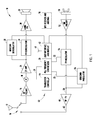
- Fig. 1 shows a transceiver 10 embodying the present invention and which includes an antenna 12 for the reception and transmission of VHF (30 - 300 MHz) frequency energy for terrestrial and satellite communications.
- the transceiver covers frequencies falling within the LMR frequency band of from 136 to 174 MHz range, the MVR frequency band of from 156 to 158 MHz, and the current communications satellite frequency range of from 137 to 150 MHz. These frequencies, of course, may change with changes in FCC regulations, and the invention is not limited to existing specific frequencies.
- the antenna 12 is coupled to a solid state transmit/receive switch 14 which typically is actuated by a user actuated push-to-talk (PTT) button switch on a handheld microphone or on a portable unit.
- PTT push-to-talk
- Such a button switch is part of the user interface circuit 42.
- antenna 12 When in a reception mode, antenna 12 is coupled to an RF preamplifier 16 which amplifies received signals and applies them to a mixer 18 coupled to an oscillator 20, which is a phase locked loop frequency synthesiser having an output 21 coupled to mixer 18 and a second output 22 coupled to an FM modulator 54, as described below.
- Mixer 18 converts the received signals depending upon the oscillator output 20 to a fixed intermediate frequency signal regardless of the incoming frequency and applies this signal to an intermediate frequency amplifier 24.
- the output of the intermediate frequency to an FM demodulator 26 for the demodulation of terrestrial based signals and to a satellite communications demodulator 28 for demodulation of satellite signals when signals modulated in the communication satellite format are received.
- Demodulators 26 and 28 may share the same hardware circuit, whose functionality is software defined.
- the output from demodulator 26 is applied to an audio amplifier 30 and subsequently to a sound reproduction device, such as a speaker 32, so that the user can receive transmitted audio information, typically speech.
- Serial data information from demodulator 28 is coupled to the user interface 42 for displaying information received.
- the control circuit 40 for the transceiver 10 includes a user interface and display 42 which typically includes an LCD, dot matrix, or other visual display of frequency channels or mode of transmission and other visible user information, as well as a keypad for entering specific information.
- the user interface and display 42 also will include controls, such as on/off power controls, squelch limit controls, volume controls, a PTT switch, and other conventional control inputs typically found in a VHF or a communication satellite transceiver.
- the control circuit 40 for transceiver 10 also includes a microprocessor 44 and interface circuits coupled to the phase locked loop frequency synthesizer 20 an user interface circuit 42 through a suitable buss.
- the microprocessor applies signals to oscillator 20 for controlling its output frequency depending upon the mode of operation of the transceiver 10 and selected frequency channel.
- Transceiver 10 also includes a microphone 50 coupled to a microphone preamplifier 52, which is coupled to the FM modulator 54 for the terrestrial transmission mode.
- a communication satellite modulator 56 is coupled to user interface 42 to receive data when in the satellite communication mode. Modulator 56 receives a satellite band frequency for modulation information from the phased locked loop oscillator 20 output 25.
- the modulators 54, 56 provide on input line 58 of RF amplifier 60, an FM or communication satellite format digital signal for transmitting by antenna 12 coupled to amplifier 60 by conductor 62 and transmit/receive switch 14.
- an uplink serial data stream in the frequency range of 148 to 150 MHz is provided to the RF amplifier 60.
- FM modulated signals in the 136 to 174 MHz range or 156 to 158 MHz frequency range, respectively, are provided.
- Modulators 54 and 56 may share the same hardware circuit, whose functionality is software defined.
- the microprocessor 44 employed in the control circuit 40 can be any number of commercially available microprocessors used in existing VHF transceivers which are reprogrammed for this application.
- the phase locked loop frequency synthesiser or oscillator 20 likewise is a conventional commercially available circuit which is coupled to the microprocessor and controlled by signals therefrom.
- the signal mode in which the system operates can be controlled manually by the operator through the user interface and display 42 circuit or microprocessor 44 can be programmed to send and receive test signals for determining whether or not a communication link is available and select the strongest signal received from one of the demodulators 26 or 28 and, based upon such signal detection, automatically select which mode of operation the transceiver 10 operates.
- Interface circuit 42 may include a serial data input port 41 for receiving externally supplied serial data for transmission. Such data could include, as only an example, e-mail from a user's PDA.
- control circuit 40 and several of the RF components of the transceiver 10 can be similar to that disclosed in U.S. Patent Application Serial No. 11/422,121 , entitled VEHICLE TELEMATICS SATELLITE DATA TRANSCEIVER UTILIZING FM RADIO CIRCUITRY filed on June 5, 2006, and assigned to the Assignee of the present invention, the disclosure of which is incorporated herein by reference.
- the signals received from the LEO satellite are currently received from Orbcomm Inc.'s constellation of thirty communication satellites which operate in the frequency of 148 - 150 MHz for uplink signals and 137 - 138 MHz for downlink signals received by transceiver 10.
- the modulators and demodulators are formatted for the modulation format of the Orbcomm Inc. communication satellites.
- One commercially available modulator/demodulator for such an application can be a DS-100 or DS-300 data modem available from Stellar Satellite Communications, Inc. and employed for the demodulator 28 and modulator 56 incorporated into a commercial VHF transceiver, such as an Icom IC-F 1721.
- the satellite service used is a subscription service for the user of the transceiver.
- a separate GPS receiver 70 is coupled to control circuit 40 through the interface circuit 42.
- the GPS receiver 70 includes its own antenna for reception of global positioning signals such as GPS, Gallileo, or other global positioning signals emanating from satellites is capable of determining an accurate geographic position of the transceiver and furnishing that information via Satellite or terrestrial communications links through the transceiver.
- the GPS chipset may be added as circuit 70 to provide GPS location data for locating the position of the mobile user in case of an emergency or to track the location of the mobile user in the normal course of business.
- a man-overboard signal can be generated by circuit 42 including GPS location information from receiver 70 and transmitted via modulator 56 and amplifier.
Landscapes
- Engineering & Computer Science (AREA)
- Computer Networks & Wireless Communication (AREA)
- Signal Processing (AREA)
- Transceivers (AREA)
- Transmitters (AREA)
Applications Claiming Priority (1)
| Application Number | Priority Date | Filing Date | Title |
|---|---|---|---|
| US11/716,203 US20080218427A1 (en) | 2007-03-09 | 2007-03-09 | Multiple mode RF communication system |
Publications (1)
| Publication Number | Publication Date |
|---|---|
| EP1968203A2 true EP1968203A2 (de) | 2008-09-10 |
Family
ID=39580501
Family Applications (1)
| Application Number | Title | Priority Date | Filing Date |
|---|---|---|---|
| EP08151887A Withdrawn EP1968203A2 (de) | 2007-03-09 | 2008-02-25 | HF-Kommunikationssystem mit mehreren Betriebsarten |
Country Status (2)
| Country | Link |
|---|---|
| US (1) | US20080218427A1 (de) |
| EP (1) | EP1968203A2 (de) |
Families Citing this family (8)
| Publication number | Priority date | Publication date | Assignee | Title |
|---|---|---|---|---|
| US8145262B2 (en) | 2005-05-17 | 2012-03-27 | Pine Valley Investments, Inc. | Multimode land mobile radio |
| US8279868B2 (en) | 2005-05-17 | 2012-10-02 | Pine Valley Investments, Inc. | System providing land mobile radio content using a cellular data network |
| US20070281626A1 (en) * | 2006-06-05 | 2007-12-06 | Dobosz Paul J | Vehicle telematics satellite data transceiver utilizing fm radio circuitry |
| US8194682B2 (en) | 2006-08-07 | 2012-06-05 | Pine Valley Investments, Inc. | Multiple protocol land mobile radio system |
| US8406168B2 (en) | 2009-03-13 | 2013-03-26 | Harris Corporation | Asymmetric broadband data radio network |
| US9363794B1 (en) * | 2014-12-15 | 2016-06-07 | Motorola Solutions, Inc. | Hybrid antenna for portable radio communication devices |
| US10684347B2 (en) * | 2016-03-08 | 2020-06-16 | Aurora Insight Inc. | Systems and methods for measuring terrestrial spectrum from space |
| US10650621B1 (en) | 2016-09-13 | 2020-05-12 | Iocurrents, Inc. | Interfacing with a vehicular controller area network |
Citations (1)
| Publication number | Priority date | Publication date | Assignee | Title |
|---|---|---|---|---|
| US20070281626A1 (en) | 2006-06-05 | 2007-12-06 | Dobosz Paul J | Vehicle telematics satellite data transceiver utilizing fm radio circuitry |
Family Cites Families (5)
| Publication number | Priority date | Publication date | Assignee | Title |
|---|---|---|---|---|
| US5010317A (en) * | 1989-11-30 | 1991-04-23 | Motorola, Inc. | Satellite based simulcast paging system |
| US6163710A (en) * | 1997-10-20 | 2000-12-19 | Ericsson, Inc. | Method and apparatus for compliance to multiple frequency plans |
| US6714760B2 (en) * | 2001-05-10 | 2004-03-30 | Qualcomm Incorporated | Multi-mode satellite and terrestrial communication device |
| US8145262B2 (en) * | 2005-05-17 | 2012-03-27 | Pine Valley Investments, Inc. | Multimode land mobile radio |
| US8270972B2 (en) * | 2007-10-23 | 2012-09-18 | Motorola Mobility Llc | Method and apparatus for detecting an alternate wireless communication network |
-
2007
- 2007-03-09 US US11/716,203 patent/US20080218427A1/en not_active Abandoned
-
2008
- 2008-02-25 EP EP08151887A patent/EP1968203A2/de not_active Withdrawn
Patent Citations (1)
| Publication number | Priority date | Publication date | Assignee | Title |
|---|---|---|---|---|
| US20070281626A1 (en) | 2006-06-05 | 2007-12-06 | Dobosz Paul J | Vehicle telematics satellite data transceiver utilizing fm radio circuitry |
Also Published As
| Publication number | Publication date |
|---|---|
| US20080218427A1 (en) | 2008-09-11 |
Similar Documents
| Publication | Publication Date | Title |
|---|---|---|
| US20080218427A1 (en) | Multiple mode RF communication system | |
| US6208844B1 (en) | System and process for shared functional block communication transceivers with GPS capability | |
| CA2282582C (en) | Wireless communication device and system incorporating location-determining means | |
| US8750925B2 (en) | Voice data RF GPS integrated circuit | |
| EP2359484B1 (de) | Schnittstelle für drahtlose kommunikationseinrichtungen | |
| US7649493B2 (en) | System for transmitting a signal for positioning and method for producing the system | |
| EP0745867A1 (de) | Digitales, zellulares Telefon mit GPS | |
| JPH02309825A (ja) | 車両自動追跡システムの車両搭載装置 | |
| JP3734839B2 (ja) | 移動体通信システム | |
| WO2021199218A1 (ja) | 衛星通信システムにおけるアンテナ方向調整方法、可搬局装置およびアンテナ方向調整プログラム | |
| JPWO1999055019A1 (ja) | 移動体通信システム | |
| JPH08265250A (ja) | 移動体衛星通信装置 | |
| KR100640364B1 (ko) | 이동통신시스템의 통신 서비스 제공 여부를 사용자에게알리는 듀얼모드 이동통신 단말기 및 방법 | |
| US6332070B1 (en) | Method and data receiver device for reception of a radio signal containing correction data for a global navigation satellite system | |
| US20030132877A1 (en) | Systems and methods for providing position information using a wireless communication device | |
| US20040002331A1 (en) | Method and system for implementing a communications transceiver using modified GPS user equipment | |
| KR100698343B1 (ko) | Gps 능력을 가진 블록 통신 송수신기 | |
| US8412094B2 (en) | Position signal receiver | |
| KR960004153B1 (ko) | 지피에스(gps)와 무전기를 이용한 음성 및 데이타 송수신 차량식별시스템 | |
| JP2570729Y2 (ja) | コードレス電話機 | |
| KR20070023209A (ko) | 휴대용 단말기에서 라디오 방송 수신 장치 | |
| MXPA99007714A (en) | Wireless communication device and system incorporating location-determining means | |
| MXPA96002019A (es) | Telefono celular digital dispuesto para el gps | |
| JPS6395740A (ja) | 列車無線方式 | |
| EP1878301A1 (de) | Fm-sender-steuerung |
Legal Events
| Date | Code | Title | Description |
|---|---|---|---|
| PUAI | Public reference made under article 153(3) epc to a published international application that has entered the european phase |
Free format text: ORIGINAL CODE: 0009012 |
|
| AK | Designated contracting states |
Kind code of ref document: A2 Designated state(s): AT BE BG CH CY CZ DE DK EE ES FI FR GB GR HR HU IE IS IT LI LT LU LV MC MT NL NO PL PT RO SE SI SK TR |
|
| AX | Request for extension of the european patent |
Extension state: AL BA MK RS |
|
| RIN1 | Information on inventor provided before grant (corrected) |
Inventor name: WILLS, ARCHIE C. Inventor name: DOBOSZ, PAUL J. Inventor name: WILLS, ELIZABETH C. |
|
| STAA | Information on the status of an ep patent application or granted ep patent |
Free format text: STATUS: THE APPLICATION IS DEEMED TO BE WITHDRAWN |
|
| 18D | Application deemed to be withdrawn |
Effective date: 20110829 |