EP1968162A2 - Faisceau de câbles et procédé de montage d'un faisceau de câbles - Google Patents
Faisceau de câbles et procédé de montage d'un faisceau de câbles Download PDFInfo
- Publication number
- EP1968162A2 EP1968162A2 EP08002474A EP08002474A EP1968162A2 EP 1968162 A2 EP1968162 A2 EP 1968162A2 EP 08002474 A EP08002474 A EP 08002474A EP 08002474 A EP08002474 A EP 08002474A EP 1968162 A2 EP1968162 A2 EP 1968162A2
- Authority
- EP
- European Patent Office
- Prior art keywords
- end piece
- stiffener
- main
- ribbon cable
- stiffening
- Prior art date
- Legal status (The legal status is an assumption and is not a legal conclusion. Google has not performed a legal analysis and makes no representation as to the accuracy of the status listed.)
- Granted
Links
Images


Classifications
-
- H—ELECTRICITY
- H01—ELECTRIC ELEMENTS
- H01R—ELECTRICALLY-CONDUCTIVE CONNECTIONS; STRUCTURAL ASSOCIATIONS OF A PLURALITY OF MUTUALLY-INSULATED ELECTRICAL CONNECTING ELEMENTS; COUPLING DEVICES; CURRENT COLLECTORS
- H01R12/00—Structural associations of a plurality of mutually-insulated electrical connecting elements, specially adapted for printed circuits, e.g. printed circuit boards [PCB], flat or ribbon cables, or like generally planar structures, e.g. terminal strips, terminal blocks; Coupling devices specially adapted for printed circuits, flat or ribbon cables, or like generally planar structures; Terminals specially adapted for contact with, or insertion into, printed circuits, flat or ribbon cables, or like generally planar structures
- H01R12/50—Fixed connections
- H01R12/59—Fixed connections for flexible printed circuits, flat or ribbon cables or like structures
- H01R12/592—Fixed connections for flexible printed circuits, flat or ribbon cables or like structures connections to contact elements
Definitions
- the present invention relates to a wire harness and a method for mounting a wire harness.
- a ribbon cable with a plurality of conductors is used today, for example for bus lines.
- a plurality of conductors are embedded in an insulating film, wherein the individual conductors have a small cross-section and a small distance from each other.
- the object of the present invention is to provide a cable harness whose ends can be assigned in a simple and secure manner to corresponding electrical / electronic devices and can be connected to them without contact errors.
- a corresponding assembly method for a wiring harness to be created.
- the wiring harness can be supplied to a mounting location with attached Maustiffener and, for example, folded or stacked ribbon cable.
- the at least one minor stiffener has a certain predetermined positional relationship with the at least one main stiffener. Accordingly, main and auxiliary drivers can be easily identified and grasped due to their position to mount the wiring harness.
- a main stiffening end piece is connected to one end of the ribbon cable and the other end of the flat ribbon cable is preferably divided into a plurality of branch branches or wiring harness branches, on each of which a side stiffening end piece is provided.
- the main stiffening end piece is preferably connected to a central electrical / electronic device such as a central on-board computer or host computer, while the Maustiffener are each connected to peripheral devices.
- the main stiffening end piece is preferably first grasped and positioned, and then the auxiliary stiffeners are grasped and released from the latching or fastening or positioning on the main stiffener and moved to the corresponding peripheral device in order to be connected thereto to become.
- the main stiffener end has detent means and the stub end has complementary detent means to permit latching of the minor stiffener tail to the main stiffener tail.
- one of the main stiffener tail and the stiffener tail has a pair of opposed protrusions or walls, pins, bolts, etc. forming a space in which at least a portion of the other is press-fitted from the stiffener tail and the main stiffener tail.
- the Superstiffener can thus be positioned and fixed on the latching means and / or a press fit on the Hauptstiffener.
- Compression fit is to be understood here as any fit between two projections, walls, pins, bolts, etc., which allows a fixation of a portion of the Maustiffeners.
- These include, for example, a transitional and / or clearance fit, which enable a fixation of the Maustiffeners on the Hauptstiffener at a predetermined position via corresponding locking lugs or other engaging means or fasteners such as adhesive joints and / or hook and loop fasteners.
- elastically resilient levers are also conceivable. All these means are to be understood below by the term press fit.
- At least one of the main stiffener tail and the stiffener tail has a pair of boundary walls for defining a maximum ribbon cable width and a pair of markers, preferably in the form of a longitudinal groove, for defining a minimum ribbon cable width.
- a ribbon cable to be mounted has the appropriate size. For example, if a wrong ribbon cable or a ribbon cable with too large manufacturing tolerances has too high a width, this circumstance can be easily determined, since this too broad ribbon cable does not fit between the boundary walls of the stiffener. On the other hand, if the ribbon cable has too small a width, it can also be easily detected, since in this case at least one of the marks of the pair of marks is not obscured by the ribbon cable.
- At least one of the main stiffener tail and the stiffener tail has at one end of a stiffener plate a pair of marker elements, preferably recesses, for checking the positioning of the first and last traces of the ribbon cable.
- the correct positioning of the printed conductors can be checked in a simple manner by optical control, ie the first and last trace must be flush with the marker or aligned therewith or in line therewith.
- contacting errors can be avoided because the tracks can be accurately positioned and the positioning is visually verifiable.
- At least one of the main stiffener tail and the minor stiffener tail has grips and / or engagement means such as protrusions, tongues, tabs, etc. for gripping by a tool.
- the handles or gripping ribs, projections, tongues, tabs, etc. are used for the positionally accurate gripping of the main or Maustiffeners by a corresponding automatic gripping tool such as a robot arm. Due to the positionally accurate gripping of the main or Maustiffeners a prior detection of the position of the main or Maustiffeners is not required. The robot arm can access the main or Maustiffener very quickly in this way. Thus, an assembly time can be shortened and manufacturing costs can be saved.
- At least a portion of the ribbon cable is provided with a shielding film such as a copper foil and / or a shielding and / or a Ablegeflecht to increase a bearing surface of shielding films, for example, in a ground connection.
- a shielding film such as a copper foil and / or a shielding and / or a Ablegeflecht to increase a bearing surface of shielding films, for example, in a ground connection.
- the mounting of the wire harness is performed by a robot.
- the ribbon cable is adhesively attached to the stiffener tail.
- gluing the ribbon cable to the stiffener tail a simple connection process is created between the ribbon cable and the stiffener.
- FIG. 1 shows a perspective view of the cable harness with the Hauptstiffener 2 and two side by side mounted on the Hauptstiffener 2 Maustiffenern third
- FIG. 2 shows a plan view of the wiring harness with the Hauptstiffener 2 and attached thereto Maustiffener. 3
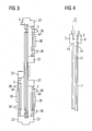
- FIG. 3 shows a front view of the Kleinstiffeners 2 with two side by side attached to the Hauptstiffener 2 Maustiffenern 3 and attached to the other side of the Hauptstiffeners 2 Maustiffener 3rd
- FIG. 4 shows a side view of the cable harness with the Hauptstiffener 2, to each of which a Crowstiffener 3 is attached to the opposite sides.
- a main stiffener 2 has a substantially flat plate 24 to which an end 12 of a ribbon cable 1 is attached.
- the conductors (not shown) of the ribbon cable 1 are exposed at the end 12 and the end 12 is attached to the stiffening plate 24 of the main stiffener 2 attached, for example by gluing.
- the main stiffener 2 has boundary walls (not shown) on the sides of the stiffening plate 24. These boundary walls serve to define a maximum width of the ribbon cable. If by mistake a too wide ribbon cable to be connected to the Kleinstiffener 2, this error is detected immediately by the fact that the ribbon cable 1 does not fit between the boundary walls of the Hauptstiffeners 2, i. a space between the boundary walls has a smaller width than the width of the ribbon cable.
- the stiffener plate 24 of the main stiffener 2 further includes a pair of markers (not shown) for defining a minimum ribbon cable width.
- These markings may for example have the shape of a longitudinal groove. If a ribbon cable 1 has a suitable width greater than the minimum width of a ribbon cable, this case can be detected by the markings such as the longitudinal grooves through the Ribbon cable 1 are covered. In contrast, if a flat cable 1 has too small a width, this error can be detected by the fact that the two markings, such as the longitudinal grooves are not completely covered by the width of the ribbon cable. 1
- a suitable width of the ribbon cable 1 can be detected within the limits of a minimum width and a maximum width by inserting the width of the ribbon cable 1 into the space between the boundary walls and at the same time marking such as the longitudinal grooves through the ribbon cable 1 to be covered.
- the ribbon cable 1 is preferably glued by a suitable adhesive with the Hauptstiffener 2.
- the auxiliary stiffener 3 is constructed substantially the same as the main stiffener 2, i.
- the Maustiffener 3 preferably also has a pair (not shown) of boundary walls and a pair (not shown) longitudinal grooves for detecting a suitable width of a ribbon cable 1.
- the Maustiffener 3 also has a stiffening plate 34 for attaching an end 14 of the ribbon cable 1. Die Head of the end 14 of the ribbon cable 1 are also exposed for this purpose and the end 14 is adhered to the stiffening plate 34 of the Maustiffeners 3.
- Both the Hauptstiffener 2 and the Maustiffener 3 preferably have handles 26, 36 or grips or gripping bars for gripping the main or Maustiffeners 2, 3 with an automatic tool or a robot arm. Furthermore, engagement means 28, 38 are arranged in the form of a projection to be gripped by the automatic tool.
- the main stiffener 2 has a pair of opposing protrusions 22 arranged at a predetermined distance from each other.
- the space between the pair of projections 22 of the Maustiffener 3 is einp motherboard. That is through Pressing the Maustiffeners 3, the Maustiffener 3 is positioned on the Feldstiffener 2 and fixed or fixed.
- a plurality of Volunteerstiffenern 3 for example, two side by side, as in FIG. 1 is shown, or on opposite sides of the Hauptstiffeners 2, as in FIGS. 3 and 4 is shown.
- the Maustiffener 3 can be attached anywhere on the Hauptstiffener 2, if appropriate engagement means such as the pair of opposing projections 22 is attached to the Feldstiffener 2 at these locations.
- a wire harness with a predetermined positional relationship between main and Maustiffenern 2, 3 is brought to a mounting location. In this way, the positional relationship of the main and Maustiffener 2, 3 to each other is already known, so that they do not need to be identified at the installation site.
- a robot arm can thus move very quickly to the predetermined position to grip a main or Maustiffener 2,3 and spend to the connection position for connecting the main or Maustiffeners 2, 3 with a connector of an electrical / electronic device or to move.
- the wiring harness can have any shape, such as the shape that one end 12 of the wiring harness 1 is connected to a Schostiffener 2, as in FIG. 1 is shown, wherein the end 12 has all the conductors of the ribbon cable 1. Furthermore, the opposite end of the ribbon cable 1 is divided into several ends 14 or split or cut. This plurality of ends 14 is connected to a plurality of Maustiffenern 3. In this way, the Hauptstiffener 2 can be connected to, for example, a central or host computer, while the Crowstiffener 3 are connected to corresponding peripherals.
- the invention is not limited to this example. It may also be attached to each end of the ribbon cable 1 a Schostiffener 2.
- the Hauptstiffener 2 complementary locking means for example, only one of the Hauptstiffener 2 has the opposite projections 22 and the other Main stiffener 2 is fitted in the space between the projections 22.
- a Hauptstiffener 2 is arranged at one end, while at the other end a Crowstiffener 3 is arranged, which receives as well as the Hauptstiffener 2, the entire width of the ribbon cable 1.
- auxiliary stiffeners 3 may be mounted at each end of the ribbon cable 1 when both ends of the ribbon cable 1 are split or sliced or cut open.
- one of the Volunteerstiffener 3 may be formed as Hauptstiffener 2 and the projections 22 or corresponding latching means for attaching the other Maustiffener 3 have.
- each main and Maustiffener 2, 3 are fixed together to form a package of Stiffenern 2, 3.
- each main and Maustiffener 2, 3 has a predetermined positional relationship to the other main and Maustiffenern 2, 3. Due to this predetermined positional relationship, the position of the Stiffener 2, 3 must not be detected, but is of known in advance.
- one of the stiffeners preferably the main stiffener 2 is gripped by an automatic tool such as a robot arm and the other stiffeners, i. the sub stiffeners 3 are gripped by other robot arms and moved to the connection positions of the peripherals and electrically connected to the respective connectors.
- the wiring harness can be mounted very quickly and automatically. Mounting errors and / or poor contact, short circuits, etc. are safely avoided.
- the Stiffener 2, 3 serves to stiffen or reinforce the end 12, 14 of the ribbon cable 1, so that this end 12, 14 can be used for secure contacting in a (not shown) jack or the like.
- the (not shown) conductors of the ribbon cable 1 are brought into contact with contact elements of the socket.
- These contact elements are for this purpose in a resilient manner in one Opening the socket arranged so that the contact elements are due to the spring force in constant contact with at least one conductor of the ribbon cable 1 when the Stiffener 2, 3 is inserted in a complete connection state in the socket, so that Stiffener 2, 3 and socket For example, they are locked together.
- the ribbon cable 1 is attached to the stiffening plate 24, 34 of the stiffener 2, 3 by gluing with a suitable adhesive such as the adhesive No. 5516B from Sekisui after the conductors of the ribbon cable 1 have been previously exposed.
- the stiffening plate 24, 34 is then inserted together with the attached thereto end 12, 14 of the ribbon cable 1 in the opening of the socket.
- connection of the ribbon cable 1 with an electrical / electronic device requires a minimum installation space and has a very small size to be accommodated in the smallest space.
- this connection can also be used in hard to reach places, since a reverse polarity protection is provided due to the only on one side of the stiffener 2, 3 existing contacts in the shape of the exposed conductor of the ribbon cable 1.
- the production costs are very low, since the ribbon cable 2 with the stiffener 2, 3 is merely glued. In this case, an unsuitable ribbon cable 2 is quickly recognized due to the boundary walls and the markings, so that a rejection rate during manufacture can be kept as low as possible.
Landscapes
- Installation Of Indoor Wiring (AREA)
Applications Claiming Priority (1)
| Application Number | Priority Date | Filing Date | Title |
|---|---|---|---|
| DE102007011148A DE102007011148A1 (de) | 2007-03-07 | 2007-03-07 | Kabelbaum und Verfahren zum Montieren des Kabelbaums |
Publications (3)
| Publication Number | Publication Date |
|---|---|
| EP1968162A2 true EP1968162A2 (fr) | 2008-09-10 |
| EP1968162A3 EP1968162A3 (fr) | 2009-12-30 |
| EP1968162B1 EP1968162B1 (fr) | 2015-04-29 |
Family
ID=39522041
Family Applications (1)
| Application Number | Title | Priority Date | Filing Date |
|---|---|---|---|
| EP20080002474 Not-in-force EP1968162B1 (fr) | 2007-03-07 | 2008-02-11 | Faisceau de câbles |
Country Status (2)
| Country | Link |
|---|---|
| EP (1) | EP1968162B1 (fr) |
| DE (1) | DE102007011148A1 (fr) |
Family Cites Families (4)
| Publication number | Priority date | Publication date | Assignee | Title |
|---|---|---|---|---|
| KR100360934B1 (ko) * | 1994-07-29 | 2003-01-24 | 닛산 지도우샤 가부시키가이샤 | 커넥터에접속가능한컨덕터단부를구비한플랫케이블 |
| US6547605B2 (en) * | 2001-07-20 | 2003-04-15 | Delphi Technologies, Inc. | Flex circuit electrical connector |
| JP2006294386A (ja) * | 2005-04-08 | 2006-10-26 | Tyco Electronics Amp Kk | 電気コネクタ、ワイヤハーネス及びワイヤハーネスの配置方法 |
| DE102005022291B4 (de) * | 2005-05-13 | 2013-06-06 | Yamaichi Electronics Deutschland Gmbh | Verbinder für ein Bandkabel |
-
2007
- 2007-03-07 DE DE102007011148A patent/DE102007011148A1/de not_active Withdrawn
-
2008
- 2008-02-11 EP EP20080002474 patent/EP1968162B1/fr not_active Not-in-force
Non-Patent Citations (1)
| Title |
|---|
| None |
Also Published As
| Publication number | Publication date |
|---|---|
| EP1968162A3 (fr) | 2009-12-30 |
| EP1968162B1 (fr) | 2015-04-29 |
| DE102007011148A1 (de) | 2008-09-11 |
Similar Documents
| Publication | Publication Date | Title |
|---|---|---|
| EP2481126B1 (fr) | Contact multibranches à insérer | |
| DE3537400A1 (de) | Gehaeuse fuer eine erweiterbare periphere interface-einheit | |
| DE69010077T2 (de) | Zusammenbau flexibler Schaltungsverbindungen. | |
| DE102014216932A1 (de) | Leiterplatte zum Montieren eines Überbrückungsmoduls und Leiterplatten-Anordnung | |
| DE60307556T2 (de) | Verbindungsstruktur von Verbindern | |
| DE112010003181B4 (de) | Stecker für eine flexible, konzentrierte Verdrahtung | |
| EP2728983A1 (fr) | Composant à plaquettes pour un appareil de commande, appareil de commande pour un véhicule automobile et agencement de traitement du signal | |
| DE2323739A1 (de) | Erdungshuelse | |
| DE112016006007T5 (de) | Fahrzeugverdrahtungssystem | |
| DE202018105110U1 (de) | Elektrisches Verbindungselement mit Anschlusspositionssicherung | |
| DE29905025U1 (de) | Verteiler zum Verbinden von Aktoren und/oder Sensoren | |
| DE6908176U (de) | Vorrichtung zur herstellung von zwischenverbindungen | |
| DE2303537C3 (de) | Elektrisch leitende Anschlußschiene und Verfahren zu ihrer Herstellung | |
| EP2095469B1 (fr) | Dispositif de montage pour recevoir des modules électroniques | |
| DE102017217104A1 (de) | Haltestruktur für elektronische Komponente, elektrischer Anschlusskasten und Kabelbaum | |
| DE69410138T2 (de) | Elektrischer Verbinder mit programmierbarem Ein-/Ausgang | |
| EP1968162B1 (fr) | Faisceau de câbles | |
| EP1722443B1 (fr) | Connecteur pour câble-ruban | |
| WO2012031808A1 (fr) | Système de raccordement et unité de réception pour un appareil de commande | |
| WO2022189046A1 (fr) | Dispositif de connexion pour fixer des composants électroniques sur une carte de circuit imprimé | |
| DE10301474B4 (de) | Verfahren zum Montieren eines Verbinders | |
| DE19526330C2 (de) | Vorrichtung zur Herstellung einer elektrischen und/oder optischen Verbindung | |
| EP1850159A2 (fr) | Connecteur à fiches pour un câble, câble doté d'un connecteur à fiches et procédé de raccordement d'un câble à un connecteur à fiches | |
| DE3904542C2 (de) | Kontaktvorrichtung | |
| EP1889334B1 (fr) | Dispositif de contact destine a minimiser la charge de zones de brasage smt sollicitees par des contraintes mecaniques |
Legal Events
| Date | Code | Title | Description |
|---|---|---|---|
| PUAI | Public reference made under article 153(3) epc to a published international application that has entered the european phase |
Free format text: ORIGINAL CODE: 0009012 |
|
| AK | Designated contracting states |
Kind code of ref document: A2 Designated state(s): AT BE BG CH CY CZ DE DK EE ES FI FR GB GR HR HU IE IS IT LI LT LU LV MC MT NL NO PL PT RO SE SI SK TR |
|
| AX | Request for extension of the european patent |
Extension state: AL BA MK RS |
|
| PUAL | Search report despatched |
Free format text: ORIGINAL CODE: 0009013 |
|
| AK | Designated contracting states |
Kind code of ref document: A3 Designated state(s): AT BE BG CH CY CZ DE DK EE ES FI FR GB GR HR HU IE IS IT LI LT LU LV MC MT NL NO PL PT RO SE SI SK TR |
|
| AX | Request for extension of the european patent |
Extension state: AL BA MK RS |
|
| 17P | Request for examination filed |
Effective date: 20100629 |
|
| AKX | Designation fees paid |
Designated state(s): AT BE BG CH CY CZ DE DK EE ES FI FR GB GR HR HU IE IS IT LI LT LU LV MC MT NL NO PL PT RO SE SI SK TR |
|
| 17Q | First examination report despatched |
Effective date: 20120308 |
|
| RAP1 | Party data changed (applicant data changed or rights of an application transferred) |
Owner name: YAMAICHI ELECTRONICS DEUTSCHLAND GMBH |
|
| REG | Reference to a national code |
Ref country code: DE Ref legal event code: R079 Ref document number: 502008012921 Country of ref document: DE Free format text: PREVIOUS MAIN CLASS: H01R0012080000 Ipc: H01R0012590000 |
|
| RIC1 | Information provided on ipc code assigned before grant |
Ipc: H01R 12/59 20110101AFI20140924BHEP |
|
| GRAP | Despatch of communication of intention to grant a patent |
Free format text: ORIGINAL CODE: EPIDOSNIGR1 |
|
| INTG | Intention to grant announced |
Effective date: 20141126 |
|
| GRAS | Grant fee paid |
Free format text: ORIGINAL CODE: EPIDOSNIGR3 |
|
| GRAA | (expected) grant |
Free format text: ORIGINAL CODE: 0009210 |
|
| AK | Designated contracting states |
Kind code of ref document: B1 Designated state(s): AT BE BG CH CY CZ DE DK EE ES FI FR GB GR HR HU IE IS IT LI LT LU LV MC MT NL NO PL PT RO SE SI SK TR |
|
| REG | Reference to a national code |
Ref country code: GB Ref legal event code: FG4D Free format text: NOT ENGLISH |
|
| REG | Reference to a national code |
Ref country code: CH Ref legal event code: EP |
|
| REG | Reference to a national code |
Ref country code: AT Ref legal event code: REF Ref document number: 724894 Country of ref document: AT Kind code of ref document: T Effective date: 20150515 |
|
| REG | Reference to a national code |
Ref country code: IE Ref legal event code: FG4D Free format text: LANGUAGE OF EP DOCUMENT: GERMAN |
|
| REG | Reference to a national code |
Ref country code: DE Ref legal event code: R096 Ref document number: 502008012921 Country of ref document: DE Effective date: 20150603 |
|
| REG | Reference to a national code |
Ref country code: NL Ref legal event code: VDEP Effective date: 20150429 |
|
| REG | Reference to a national code |
Ref country code: LT Ref legal event code: MG4D |
|
| PG25 | Lapsed in a contracting state [announced via postgrant information from national office to epo] |
Ref country code: NL Free format text: LAPSE BECAUSE OF FAILURE TO SUBMIT A TRANSLATION OF THE DESCRIPTION OR TO PAY THE FEE WITHIN THE PRESCRIBED TIME-LIMIT Effective date: 20150429 |
|
| PG25 | Lapsed in a contracting state [announced via postgrant information from national office to epo] |
Ref country code: PT Free format text: LAPSE BECAUSE OF FAILURE TO SUBMIT A TRANSLATION OF THE DESCRIPTION OR TO PAY THE FEE WITHIN THE PRESCRIBED TIME-LIMIT Effective date: 20150831 Ref country code: FI Free format text: LAPSE BECAUSE OF FAILURE TO SUBMIT A TRANSLATION OF THE DESCRIPTION OR TO PAY THE FEE WITHIN THE PRESCRIBED TIME-LIMIT Effective date: 20150429 Ref country code: NO Free format text: LAPSE BECAUSE OF FAILURE TO SUBMIT A TRANSLATION OF THE DESCRIPTION OR TO PAY THE FEE WITHIN THE PRESCRIBED TIME-LIMIT Effective date: 20150729 Ref country code: HR Free format text: LAPSE BECAUSE OF FAILURE TO SUBMIT A TRANSLATION OF THE DESCRIPTION OR TO PAY THE FEE WITHIN THE PRESCRIBED TIME-LIMIT Effective date: 20150429 Ref country code: LT Free format text: LAPSE BECAUSE OF FAILURE TO SUBMIT A TRANSLATION OF THE DESCRIPTION OR TO PAY THE FEE WITHIN THE PRESCRIBED TIME-LIMIT Effective date: 20150429 Ref country code: ES Free format text: LAPSE BECAUSE OF FAILURE TO SUBMIT A TRANSLATION OF THE DESCRIPTION OR TO PAY THE FEE WITHIN THE PRESCRIBED TIME-LIMIT Effective date: 20150429 |
|
| PG25 | Lapsed in a contracting state [announced via postgrant information from national office to epo] |
Ref country code: IS Free format text: LAPSE BECAUSE OF FAILURE TO SUBMIT A TRANSLATION OF THE DESCRIPTION OR TO PAY THE FEE WITHIN THE PRESCRIBED TIME-LIMIT Effective date: 20150829 Ref country code: LV Free format text: LAPSE BECAUSE OF FAILURE TO SUBMIT A TRANSLATION OF THE DESCRIPTION OR TO PAY THE FEE WITHIN THE PRESCRIBED TIME-LIMIT Effective date: 20150429 Ref country code: GR Free format text: LAPSE BECAUSE OF FAILURE TO SUBMIT A TRANSLATION OF THE DESCRIPTION OR TO PAY THE FEE WITHIN THE PRESCRIBED TIME-LIMIT Effective date: 20150730 |
|
| REG | Reference to a national code |
Ref country code: FR Ref legal event code: PLFP Year of fee payment: 9 |
|
| PG25 | Lapsed in a contracting state [announced via postgrant information from national office to epo] |
Ref country code: EE Free format text: LAPSE BECAUSE OF FAILURE TO SUBMIT A TRANSLATION OF THE DESCRIPTION OR TO PAY THE FEE WITHIN THE PRESCRIBED TIME-LIMIT Effective date: 20150429 Ref country code: DK Free format text: LAPSE BECAUSE OF FAILURE TO SUBMIT A TRANSLATION OF THE DESCRIPTION OR TO PAY THE FEE WITHIN THE PRESCRIBED TIME-LIMIT Effective date: 20150429 |
|
| REG | Reference to a national code |
Ref country code: DE Ref legal event code: R097 Ref document number: 502008012921 Country of ref document: DE |
|
| PG25 | Lapsed in a contracting state [announced via postgrant information from national office to epo] |
Ref country code: CZ Free format text: LAPSE BECAUSE OF FAILURE TO SUBMIT A TRANSLATION OF THE DESCRIPTION OR TO PAY THE FEE WITHIN THE PRESCRIBED TIME-LIMIT Effective date: 20150429 Ref country code: RO Free format text: LAPSE BECAUSE OF NON-PAYMENT OF DUE FEES Effective date: 20150429 Ref country code: PL Free format text: LAPSE BECAUSE OF FAILURE TO SUBMIT A TRANSLATION OF THE DESCRIPTION OR TO PAY THE FEE WITHIN THE PRESCRIBED TIME-LIMIT Effective date: 20150429 Ref country code: SK Free format text: LAPSE BECAUSE OF FAILURE TO SUBMIT A TRANSLATION OF THE DESCRIPTION OR TO PAY THE FEE WITHIN THE PRESCRIBED TIME-LIMIT Effective date: 20150429 |
|
| PLBE | No opposition filed within time limit |
Free format text: ORIGINAL CODE: 0009261 |
|
| STAA | Information on the status of an ep patent application or granted ep patent |
Free format text: STATUS: NO OPPOSITION FILED WITHIN TIME LIMIT |
|
| 26N | No opposition filed |
Effective date: 20160201 |
|
| PG25 | Lapsed in a contracting state [announced via postgrant information from national office to epo] |
Ref country code: IT Free format text: LAPSE BECAUSE OF FAILURE TO SUBMIT A TRANSLATION OF THE DESCRIPTION OR TO PAY THE FEE WITHIN THE PRESCRIBED TIME-LIMIT Effective date: 20150429 |
|
| PG25 | Lapsed in a contracting state [announced via postgrant information from national office to epo] |
Ref country code: SI Free format text: LAPSE BECAUSE OF FAILURE TO SUBMIT A TRANSLATION OF THE DESCRIPTION OR TO PAY THE FEE WITHIN THE PRESCRIBED TIME-LIMIT Effective date: 20150429 Ref country code: BE Free format text: LAPSE BECAUSE OF NON-PAYMENT OF DUE FEES Effective date: 20160229 |
|
| PG25 | Lapsed in a contracting state [announced via postgrant information from national office to epo] |
Ref country code: LU Free format text: LAPSE BECAUSE OF FAILURE TO SUBMIT A TRANSLATION OF THE DESCRIPTION OR TO PAY THE FEE WITHIN THE PRESCRIBED TIME-LIMIT Effective date: 20160211 Ref country code: MC Free format text: LAPSE BECAUSE OF FAILURE TO SUBMIT A TRANSLATION OF THE DESCRIPTION OR TO PAY THE FEE WITHIN THE PRESCRIBED TIME-LIMIT Effective date: 20150429 |
|
| REG | Reference to a national code |
Ref country code: CH Ref legal event code: PL |
|
| PG25 | Lapsed in a contracting state [announced via postgrant information from national office to epo] |
Ref country code: LI Free format text: LAPSE BECAUSE OF NON-PAYMENT OF DUE FEES Effective date: 20160229 Ref country code: CH Free format text: LAPSE BECAUSE OF NON-PAYMENT OF DUE FEES Effective date: 20160229 |
|
| REG | Reference to a national code |
Ref country code: IE Ref legal event code: MM4A |
|
| PG25 | Lapsed in a contracting state [announced via postgrant information from national office to epo] |
Ref country code: IE Free format text: LAPSE BECAUSE OF NON-PAYMENT OF DUE FEES Effective date: 20160211 |
|
| REG | Reference to a national code |
Ref country code: FR Ref legal event code: PLFP Year of fee payment: 10 |
|
| REG | Reference to a national code |
Ref country code: AT Ref legal event code: MM01 Ref document number: 724894 Country of ref document: AT Kind code of ref document: T Effective date: 20160211 |
|
| PG25 | Lapsed in a contracting state [announced via postgrant information from national office to epo] |
Ref country code: AT Free format text: LAPSE BECAUSE OF NON-PAYMENT OF DUE FEES Effective date: 20160211 |
|
| PG25 | Lapsed in a contracting state [announced via postgrant information from national office to epo] |
Ref country code: SE Free format text: LAPSE BECAUSE OF FAILURE TO SUBMIT A TRANSLATION OF THE DESCRIPTION OR TO PAY THE FEE WITHIN THE PRESCRIBED TIME-LIMIT Effective date: 20150429 |
|
| PG25 | Lapsed in a contracting state [announced via postgrant information from national office to epo] |
Ref country code: MT Free format text: LAPSE BECAUSE OF FAILURE TO SUBMIT A TRANSLATION OF THE DESCRIPTION OR TO PAY THE FEE WITHIN THE PRESCRIBED TIME-LIMIT Effective date: 20150429 |
|
| REG | Reference to a national code |
Ref country code: FR Ref legal event code: PLFP Year of fee payment: 11 |
|
| PG25 | Lapsed in a contracting state [announced via postgrant information from national office to epo] |
Ref country code: HU Free format text: LAPSE BECAUSE OF FAILURE TO SUBMIT A TRANSLATION OF THE DESCRIPTION OR TO PAY THE FEE WITHIN THE PRESCRIBED TIME-LIMIT; INVALID AB INITIO Effective date: 20080211 Ref country code: CY Free format text: LAPSE BECAUSE OF FAILURE TO SUBMIT A TRANSLATION OF THE DESCRIPTION OR TO PAY THE FEE WITHIN THE PRESCRIBED TIME-LIMIT Effective date: 20150429 |
|
| PG25 | Lapsed in a contracting state [announced via postgrant information from national office to epo] |
Ref country code: TR Free format text: LAPSE BECAUSE OF FAILURE TO SUBMIT A TRANSLATION OF THE DESCRIPTION OR TO PAY THE FEE WITHIN THE PRESCRIBED TIME-LIMIT Effective date: 20150429 |
|
| PG25 | Lapsed in a contracting state [announced via postgrant information from national office to epo] |
Ref country code: BG Free format text: LAPSE BECAUSE OF FAILURE TO SUBMIT A TRANSLATION OF THE DESCRIPTION OR TO PAY THE FEE WITHIN THE PRESCRIBED TIME-LIMIT Effective date: 20150429 |
|
| PGFP | Annual fee paid to national office [announced via postgrant information from national office to epo] |
Ref country code: DE Payment date: 20240221 Year of fee payment: 17 Ref country code: GB Payment date: 20240209 Year of fee payment: 17 |
|
| PGFP | Annual fee paid to national office [announced via postgrant information from national office to epo] |
Ref country code: FR Payment date: 20240220 Year of fee payment: 17 |
|
| REG | Reference to a national code |
Ref country code: DE Ref legal event code: R119 Ref document number: 502008012921 Country of ref document: DE |
|
| GBPC | Gb: european patent ceased through non-payment of renewal fee |
Effective date: 20250211 |
|
| PG25 | Lapsed in a contracting state [announced via postgrant information from national office to epo] |
Ref country code: DE Free format text: LAPSE BECAUSE OF NON-PAYMENT OF DUE FEES Effective date: 20250902 |
|
| PG25 | Lapsed in a contracting state [announced via postgrant information from national office to epo] |
Ref country code: GB Free format text: LAPSE BECAUSE OF NON-PAYMENT OF DUE FEES Effective date: 20250211 |
|
| PG25 | Lapsed in a contracting state [announced via postgrant information from national office to epo] |
Ref country code: FR Free format text: LAPSE BECAUSE OF NON-PAYMENT OF DUE FEES Effective date: 20250228 |