EP1967828B1 - Fluidzähler - Google Patents
Fluidzähler Download PDFInfo
- Publication number
- EP1967828B1 EP1967828B1 EP08002345.0A EP08002345A EP1967828B1 EP 1967828 B1 EP1967828 B1 EP 1967828B1 EP 08002345 A EP08002345 A EP 08002345A EP 1967828 B1 EP1967828 B1 EP 1967828B1
- Authority
- EP
- European Patent Office
- Prior art keywords
- measuring tube
- housing
- fluid counter
- counter according
- holding part
- Prior art date
- Legal status (The legal status is an assumption and is not a legal conclusion. Google has not performed a legal analysis and makes no representation as to the accuracy of the status listed.)
- Active
Links
Images


Classifications
-
- G—PHYSICS
- G01—MEASURING; TESTING
- G01F—MEASURING VOLUME, VOLUME FLOW, MASS FLOW OR LIQUID LEVEL; METERING BY VOLUME
- G01F1/00—Measuring the volume flow or mass flow of fluid or fluent solid material wherein the fluid passes through a meter in a continuous flow
- G01F1/66—Measuring the volume flow or mass flow of fluid or fluent solid material wherein the fluid passes through a meter in a continuous flow by measuring frequency, phase shift or propagation time of electromagnetic or other waves, e.g. using ultrasonic flowmeters
- G01F1/662—Constructional details
-
- G—PHYSICS
- G01—MEASURING; TESTING
- G01F—MEASURING VOLUME, VOLUME FLOW, MASS FLOW OR LIQUID LEVEL; METERING BY VOLUME
- G01F1/00—Measuring the volume flow or mass flow of fluid or fluent solid material wherein the fluid passes through a meter in a continuous flow
- G01F1/74—Devices for measuring flow of a fluid or flow of a fluent solid material in suspension in another fluid
Definitions
- the present invention relates to a fluid meter with a measuring tube housing. a measuring path located in the measuring tube housing, an ultrasonic transducer assembly of at least one ultrasonic transducer for generating an ultrasonic signal and / or for converting a measuring path passing ultrasonic signal into an electrical signal and a deflection device for deflecting the ultrasonic signal in the longitudinal direction of the measuring tube according to the preamble of claim 1.
- An ultrasonic counter according to the preamble of claim 1 is known from WO 00/23773 known.
- a plurality of ultrasonic transducers is placed on the outside of a pipeline, the surface normal is arranged perpendicular to the longitudinal axis of the pipeline.
- the ultrasonic transducers can be arranged in a relation to the clockwise position 1 - 5 clock position or 7 - 11 clock position on the pipeline.
- the ultrasound transducers are positioned on the outside of the pipeline such that their surface normal lies obliquely to the longitudinal axis of the measuring tube.
- the ultrasonic transducers are connected to a separate electronics housing, which also has a display.
- a heat meter which has a connection housing and a directly on the connection housing includes attached electronics housing without display.
- a separate calculator with display is provided.
- the calculator can be positioned directly at the heat meter at a right angle to the electronics housing.
- the calculator can also be mounted remotely from the heat meter on the wall or be located away from the heat meter in a control panel.
- An optional fitting allows the calculator to be positioned directly on the heat meter instead of in a horizontal or vertical position, even in an angled position.
- the US 2002/0124661 A1 shows a device for measuring flows, in which the ultrasonic transducers can also be arranged laterally inclined with respect to the cross section of the measuring tube, but the surface normal is also arranged to extend obliquely to the longitudinal axis of the measuring tube.
- the EP 1 096 236 A2 describes an ultrasonic flowmeter for fluids in which the surface normal of the respective ultrasound transducer is arranged parallel to the longitudinal axis of the measuring tube and the ultrasound signal leaving the respective ultrasound transducer is reflected at an angle in the measuring tube curvature obliquely to the opposite wall of the measuring tube and from there also obliquely undreflektiert, until it reaches the second ultrasonic transducer.
- the DE 103 27 076 B3 describes a fluid meter comprising a multi-part measuring tube arrangement.
- a brass measuring tube is located inside a measuring tube housing.
- the ultrasonic transducers are at the top the measuring tube housing positioned in a corresponding recess.
- At the top of the converter are usually the electronic board and the display element in each case in a parallel arrangement to the ultrasonic transducer surface.
- As standardized installation level is in a horizontal pipe z. B. for the medium water a display with horizontally oriented ie horizontally oriented display level or rotated by 90 ° (vertical) display level and a vertical pipe a display with a vertical display level provided.
- the horizontal installation level with a horizontal, ie horizontal, display level is the most common installation position that occurs in practice.
- the ultrasonic transducer sits because of the most important, above-described arrangements therefore at the highest fluid-flow point. This results in the disadvantage that in the fluid located gas bubbles settle on the surface of the transducer and thereby cause interference in the measurement.
- a rotation of the entire fluid counter to avoid occupancy of Wandlerobertlächen with gas bubbles is not possible because fluid meter must be mounted in a well-defined mounting positions and in a rotation also the readability of the display device would no longer be guaranteed. The installation situation is therefore set only very narrow limits.
- An ultrasonic flowmeter with a U-shaped measuring tube housing is known.
- the measuring tube housing is surrounded by a further housing which comprises a main housing part, a bottom part and a lid.
- the bottom part and the main housing part form a receptacle for the measuring tube housing.
- Electronic parts are located inside the main body.
- the object of the present invention is to provide a generic fluid meter, in which on the one hand measurement inaccuracies due to gas bubbles in the area of the surface of the transducer are avoided, on the other hand, the narrow specifications can be met when installing fluid meters.
- the present object is achieved in the generic fluid meter by the features of the characterizing part of claim 1.
- a further housing for receiving electronic parts is provided, wherein the measuring tube housing is housed in a holding device which is mountable to the housing. Due to the conceptual separation of these two housing and their angular offset connectivity via the holding device, the two housings can be positioned in a simple manner in a desired angular position to each other.
- the ultrasonic transducer (s) no longer lie at the uppermost position of the space through which the medium flows, but lower. As a result, the gas bubbles present in the fluid are collected at a location inside the counter at which they have no effect on the accuracy of the measurement.
- the good readability of the fluid meter remains through the display device, which is still located at the highest point.
- the invention ensures that the fluid meter is easy to read and the provisions of a standard-compliant installation met while disturbances due to air bubbles on the top of the measuring tube housing can be effectively excluded.
- the lateral angular offset of the surface normal N of the ultrasonic transducer is perpendicular to the display plane A in an angular range between 30 ° - 60 °, preferably 40 ° - 50 °, particularly preferably 42 ° - 48 °.
- the angle can be 45 °.
- the ultrasonic signal in installation position from the bottom meets the deflection device.
- the advantage of the lateral angular offset of 30 ° - 60 ° is also due to the fact that when the display unit is rotated by 90 ° from the mounting plane to laterally read the meter, also the converter is not the highest Stand point and thus the air bubbles can then only accumulate laterally to the converter. This would not be guaranteed at an angle of 90 °.
- the aforementioned angle data of the surface normal N of the ultrasonic transducer relate to the perpendicular to the display plane A of the display element or at least one holding device for an external display element.
- the holding device is designed such that the measuring tube housing can be clamped in the holding device.
- This type of mechanical fixation makes it possible to dispense with expensive work (such as, for example, the introduction of threaded bores) on the measuring tube housing, which consists in particular of metal. Only minor mechanical processing of the measuring tube housing (eg the introduction of receiving lugs for temperature sensors and / or through-holes for ultrasonic signals) is necessary. As a result, the number of parts can be reduced and the cost of production can be significantly reduced.
- the holding device has a first holding part and a second holding part, which form a recess for receiving the measuring tube, a structurally particularly simple solution for fixing is created.
- the holding device of the aforementioned type surrounds the measuring tube housing in the manner of a clamp.
- the previously described type of fastening has the additional advantage that at least one functional part can be held in position by the encompassing retaining device.
- the functional part is, for example, a transducer which is located in a pocket or recess, for example on the holding part, and / or around a temperature sensor. It must only be provided recesses for these functional parts, which are processing technology easy to implement.
- the fixation is done by the embrace of the holding device. This wraparound of the holding device prevents the elements to be held (transducer / T-probe) from being pushed out of position due to the internal pressure of the medium.
- an anti-rotation device can be provided between the measuring tube housing and the holding device, for example in the form of a projection on the holding device, which engages in a corresponding recess on the measuring tube housing or vice versa.
- the second holding part it is possible to detachably connect the second holding part to the housing, for example via snap connections or the like.
- the second holding part can then be produced independently.
- the respective mounting position is provided in a region on the second holding part, which projects laterally from the housing for the electronic parts, or the mounting position (s) for attaching the first holding part is particularly easy to access.
- a kind of verandaförmiger projection of the second holding part may be provided on the housing for the electronic parts.
- At least one guide channel for a wire connection from the respective converter and / or from a temperature sensor is provided in the housing.
- the guide channel ensures during assembly a predetermined orientation and positioning of the relevant connecting wire and thus easy mounting and reducing assembly errors.
- the first holding part may expediently be designed in the manner of a shell which preferably surrounds the measuring tube housing on its underside over its length includes. Alternatively, however, several z. B. two holding parts at a distance (eg., On the front and back) the measuring tube housing for fixing the same on the second holding part in the manner of a clamp.
- the position also allows additional functional parts, e.g. a temperature sensor without complex processing measures on Meßrohrgeophuse fixed and secure to fix, in which the functional part is fixed in position in the mounting position by the housing for the electronic components or by the cross-grip part.
- additional functional parts e.g. a temperature sensor without complex processing measures on Meßrohrgeophuse fixed and secure to fix, in which the functional part is fixed in position in the mounting position by the housing for the electronic components or by the cross-grip part.
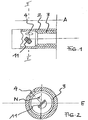
- Fig. 1 shows a highly simplified, schematic sectional view of part of a first embodiment of a fluid meter 1 according to the present invention.
- the fluid meter comprises a measuring tube housing 2, in which an elongate measuring tube 3 is positioned to ensure a measuring path.
- a deflection device 11 for example in the form of a mirror, with which an ultrasonic signal emitted by an ultrasonic transducer 4 is reflected in the longitudinal direction of the measuring tube 3 and vice versa.
- a Fig. 1 for clarity, not shown, further housing, which electronic elements, such as a display element, such as an LCD display or the like, houses.
- the level of the display element is marked with A.
- the position of the installation level is in Fig. 2 marked with E.
- the respective ultrasonic transducer 4 is not on the
- the uppermost point is arranged in the interior of the measuring tube housing 2, but instead is located at a position which is offset at an angle ⁇ at an angle to the vertical plane E of installation.
- the inclination of the surface normal N of the ultrasonic transducer 4 to the vertical of the plane E is indicated by the angle ⁇ . Gas bubbles in the fluid usually deposit at the top of the inside of the measuring tube housing and therefore do not affect the ultrasonic propagation.
- Fig. 3 the measuring tube housing 2 is shown together with a holding device 6 and the housing 8 for receiving the electronic components.
- a holding device 6 At the top of the housing 8 is an indicated by the reference numeral 7 display element, for example in the form of an LCD display.
- the display element 7 lies in the plane A (display level).
- the measuring tube housing 2 is fixed to the housing 8 via the holding device 6.
- the holding device 6 comprises a first holding part 10 which forms a recess 15 and encloses the measuring tube housing 2. Further, a second holding part 13, which in the embodiment according to Fig. 3 has a plate-like shape provided.
- the measuring tube housing 2 is clamped between the first holding part 10 and the second holding part 13, for example, in which the two holding parts 10, 13 screwed (not shown screws) so are clamped together.
- connection of the first and second holding part 10, 13 also via a one-sided hooking by means of a coordinated, one-sided hooking geometry of the first and second holding part 10. 13 and opposite screwing done.
- the ultrasonic transducer 4 is in this case, for example, in a recess 19 on the second holding part 13, which is aligned with a bore in the measuring tube housing 2. In the clamped state of the ultrasonic transducer 4 is by design held within the recess. Mechanical impairments are advantageously absorbed by the second holding part 13.
- a temperature sensor 18 is seated in a pocket 25 on the first holding part 10. Also, this temperature sensor 18 is held in the pocket 25 by design. In order to enable the first holding part 10 to be pushed on with the temperature sensor 18 preassembled, the pocket 25 runs parallel to the plane of the drawing up to the open end of the first holding part. The pocket 25 is adapted to the size of the temperature sensor 18 immersed in the first holding part. The remaining (in Fig. 3 not shown cavity) is by a (in Fig. 3 also not shown) filler z. B. made of plastic or rubber subsequently closed again.
- Into the meter tube housing 2 is e.g. formed on the ultrasonic transducer 4 opposite side, a projection 21 which engages in a corresponding recess 20 on the first holding part 10.
- a projection 21 which engages in a corresponding recess 20 on the first holding part 10.
- the second holding part 13 may be connected as a separate part with the housing 8, for example via a snap connection, clamp connection or the like.
- the level E in Fig. 3 indicates the orientation of the plane in the installation position of the fluid meter 1, which is parallel to the display plane A.
- Fig. 4 an embodiment of a non-inventive fluid meter is shown omitting the housing 8 for the electronic components.
- the measuring tube housing 2 in this case has a flange 22 with individual flange holes 23 for position predetermined mounting to the mains.
- the flange 22 is usually provided at both ends of the measuring tube housing 2.
- the design after Fig. 4 also has a housing 8 for the electronic components, which, however, in Fig. 4 for the sake of clarity is not shown.
- the first holding part 10 of the holding device 6 is an integral part of the measuring tube housing 2.
- the measuring tube housing can, for. B. made of plastic in a production step.
- Fig. 5A shows the housing 8 for the electronic components and the second holding part 13 of the holding device 6 for the measuring tube housing 2.
- the housing recess 12 is provided to receive a display element, such as an LCD display or the like. Furthermore, in the region of the housing recess 12, a circuit board with components of the control electronics, the electronics for the measured value processing and the data transfer.
- a guide channel 14 for the line connection of a temperature sensor.
- the housing 8 is detachably connected to the second holding part 13 via a plurality of snap connections 16 and in this case dimensioned such that the second holding part 13 forms a circumferential projection 17 which covers the individual mounting positions, e.g. Through holes, picks up.
- Both the second holding part 13 and the housing 8 are preferably designed as plastic moldings.
- Locking connections with the housing 8 is connectable.
- the first holding part 10 which in this case has the shape of a trough, almost over the entire length of the measuring tube housing 2 and fixes this in its position.
- a standardized arrangement consisting of housing 8 and second holding part 13 can be used for measuring tube housing 2 with different nominal diameters (for example nominal diameter DN 15 - DN 100).
- FIG. 5A and 5B illustrated differently arranged mounting positions 9 make it possible to attach different sized measuring tube housing 2 by selecting the mounting positions.
- the second holding part 13 acts like an adapter.
- Fig. 7 shows a further embodiment of the fluid meter in a highly simplified representation.
- a one-piece holding device 6 which has the shape of a circumferential bracket or ring provided.
- the holding device 6 is pushed in the longitudinal direction, ie axially relative to the longitudinal direction of the measuring tube 3, and fixed to the housing 8.
- a (not shown) latching between overlapping part and a lug 28 can be provided on the housing 8 for fixing a (not shown) latching between overlapping part and a lug 28.
- the measuring tube housing 2 can be clamped in a fixed position between the gripping part and the housing 8.
- the projection 28 may be formed integrally with the housing or be connectable to the housing 8, for example via a snap connection.
- a screw 29 may additionally be provided for fixing the position of the holding device 6, for tolerance compensation and for clamping the measuring tube housing.
- a rubber layer is provided between the measuring tube housing 2 and the projection 28, which also compensates for tolerances and serves to seal the (also not shown) ultrasonic transducer.
- a rubber layer is provided between the measuring tube housing 2 and the projection 28, which also compensates for tolerances and serves to seal the (also not shown) ultrasonic transducer.
- the rubber layer and other resilient elements such as a compression spring or the like, can be used to compensate for tolerances.
- the embodiment according to Fig. 8 shows a housing 8 with an upper-side display element 7.
- the holding device 6 is formed as a C-shaped bracket. which is connected via a hinge 26 with the housing 8 in connection.
- the housing 8 and the holding device 6 together form a recess 15 for receiving the measuring tube housing 2.
- a cable 30 is guided in the bracket of the holding device 6 to the electronic components of the housing 8.
- the measuring tube housing 2 is inserted, for example after sealing (casting) of the housing 8 in the bracket. Subsequently, the bracket is folded up and snapped to the snap connection 27 with the housing 8.
Landscapes
- Physics & Mathematics (AREA)
- Fluid Mechanics (AREA)
- General Physics & Mathematics (AREA)
- Electromagnetism (AREA)
- Measuring Volume Flow (AREA)
Priority Applications (4)
| Application Number | Priority Date | Filing Date | Title |
|---|---|---|---|
| PL16157601T PL3043154T3 (pl) | 2007-03-09 | 2008-02-08 | Licznik płynu |
| DK16157601.2T DK3043154T3 (da) | 2007-03-09 | 2008-02-08 | Fluidmåler |
| EP16157601.2A EP3043154B1 (de) | 2007-03-09 | 2008-02-08 | Fluidzähler |
| PL08002345T PL1967828T3 (pl) | 2007-03-09 | 2008-02-08 | Licznik płynu |
Applications Claiming Priority (1)
| Application Number | Priority Date | Filing Date | Title |
|---|---|---|---|
| DE102007011546A DE102007011546B4 (de) | 2007-03-09 | 2007-03-09 | Fluidzähler |
Related Child Applications (2)
| Application Number | Title | Priority Date | Filing Date |
|---|---|---|---|
| EP16157601.2A Division-Into EP3043154B1 (de) | 2007-03-09 | 2008-02-08 | Fluidzähler |
| EP16157601.2A Division EP3043154B1 (de) | 2007-03-09 | 2008-02-08 | Fluidzähler |
Publications (2)
| Publication Number | Publication Date |
|---|---|
| EP1967828A1 EP1967828A1 (de) | 2008-09-10 |
| EP1967828B1 true EP1967828B1 (de) | 2017-12-27 |
Family
ID=39553599
Family Applications (2)
| Application Number | Title | Priority Date | Filing Date |
|---|---|---|---|
| EP08002345.0A Active EP1967828B1 (de) | 2007-03-09 | 2008-02-08 | Fluidzähler |
| EP16157601.2A Active EP3043154B1 (de) | 2007-03-09 | 2008-02-08 | Fluidzähler |
Family Applications After (1)
| Application Number | Title | Priority Date | Filing Date |
|---|---|---|---|
| EP16157601.2A Active EP3043154B1 (de) | 2007-03-09 | 2008-02-08 | Fluidzähler |
Country Status (5)
| Country | Link |
|---|---|
| US (1) | US7819021B2 (pl) |
| EP (2) | EP1967828B1 (pl) |
| DE (1) | DE102007011546B4 (pl) |
| DK (2) | DK1967828T3 (pl) |
| PL (2) | PL1967828T3 (pl) |
Cited By (1)
| Publication number | Priority date | Publication date | Assignee | Title |
|---|---|---|---|---|
| RU2770172C1 (ru) * | 2018-10-25 | 2022-04-14 | СЕНСУС СПЕКТРУМ ЭлЭлСи | Измерительное устройство для определения расхода текучей среды, протекающей через участок трубы |
Families Citing this family (14)
| Publication number | Priority date | Publication date | Assignee | Title |
|---|---|---|---|---|
| DE202008014171U1 (de) * | 2008-10-24 | 2010-03-25 | Körner, Hans-Holger | Durchflussmengenmesseinrichtung |
| EP2236993A1 (en) | 2009-04-02 | 2010-10-06 | Kamstrup A/S | Flow meter with housing and separate unit |
| EP2236994A1 (en) | 2009-04-02 | 2010-10-06 | Kamstrup A/S | Flow meter with common protection membrane |
| DK177040B1 (en) * | 2010-04-12 | 2011-02-28 | Miitors Aps | Ultrasonic consumer meter with locking mechanism |
| JP4878653B1 (ja) * | 2011-01-28 | 2012-02-15 | 株式会社アツデン | 超音波流量測定装置 |
| DE102011101257B4 (de) * | 2011-05-11 | 2012-12-20 | Hydrometer Gmbh | Durchflussmesser und Verfahren zur Herstellung eines Durchflussmessers |
| EP2758753B1 (en) | 2011-09-23 | 2016-02-24 | Kamstrup A/S | Flow meter with protruding transducers |
| DE102012001771A1 (de) * | 2012-01-31 | 2013-08-01 | Hydrometer Gmbh | Verbrauchsmessgerät |
| US8928137B2 (en) | 2013-05-15 | 2015-01-06 | Kamstrup A/S | Flow meter with ultrasound transducer directly connected to and fixed to measurement circuit board |
| US8997584B1 (en) * | 2013-07-26 | 2015-04-07 | Onicon, Inc. | Radial mode transducer flow meter |
| CA2952064C (en) * | 2014-06-10 | 2020-04-07 | Soneter, Inc. | Sensor assembly |
| DE102015014267A1 (de) * | 2015-11-05 | 2017-05-11 | Diehl Metering Gmbh | Messeinrichtung zum Erfassen wenigstens eines Messwerts eines fluiden Mediums |
| DE202018102622U1 (de) | 2018-05-09 | 2018-05-18 | Zenner International Gmbh & Co. Kg | Ultraschallzähler |
| US10809106B2 (en) * | 2019-02-18 | 2020-10-20 | Badger Meter, Inc. | Ultrasonic flow meter configured to facilitate measurement electronics replacement |
Citations (1)
| Publication number | Priority date | Publication date | Assignee | Title |
|---|---|---|---|---|
| GB2429061A (en) * | 2005-08-13 | 2007-02-14 | Flownetix Ltd | Enclosure for ultrasonic flowmeter |
Family Cites Families (18)
| Publication number | Priority date | Publication date | Assignee | Title |
|---|---|---|---|---|
| US4004461A (en) * | 1975-11-07 | 1977-01-25 | Panametrics, Inc. | Ultrasonic measuring system with isolation means |
| DE9202970U1 (de) * | 1992-03-06 | 1992-07-23 | Wagner, Louise, 83471 Berchtesgaden | Vorrichtung zur Messung einer physikalischen Größe eines Fluidstroms in einer Leitung |
| NL9301422A (nl) * | 1993-08-17 | 1995-03-16 | Servex Bv | Werkwijze en inrichting voor het bepalen van eigenschappen van de stroming van een medium. |
| DK9400174Y6 (da) * | 1994-04-14 | 1994-07-22 | Kamstrup As | Strømningsmåler til måling af en fluidumstrøm gennem en strømningskanal |
| DE19503714A1 (de) * | 1995-02-04 | 1996-08-08 | Suedrohrbau Gmbh & Co | Anordnung zur Bestimmung der Strömungsgeschwindigkeit eines Fluides in Rohren mit kreisförmigem Querschnitt mittels Ultraschall |
| DE29621964U1 (de) * | 1996-12-18 | 1997-03-20 | Hydrometer GmbH, 91522 Ansbach | Ultraschallwandler für Durchflußmeßgeräte |
| NL1006007C2 (nl) * | 1997-05-07 | 1998-11-10 | A Hak Ind Services B V | Ultrasoon meetinstrument. |
| DE19729473A1 (de) * | 1997-07-10 | 1999-02-04 | Meinecke Ag H | Ultraschall-Durchflußmesser |
| DE19861073A1 (de) | 1998-03-02 | 1999-11-04 | Georg F Wagner | Durchflußmeßvorrichtung |
| DE19808701C2 (de) * | 1998-03-02 | 2000-01-20 | Georg F Wagner | Durchflussmessvorrichtung |
| US6330831B1 (en) | 1998-10-20 | 2001-12-18 | Panametrics, Inc. | Stream-cleaned differential reflection coefficient sensor |
| SI20391A (sl) | 1999-09-06 | 2001-04-30 | Iskraemeco Merjenje In Upravljanje Energije D.D. | Merilna cev ultrazvočnega merilnika prostorninskega pretoka fluidov |
| DE10047383C1 (de) | 2000-09-25 | 2001-11-08 | Siemens Ag | Ultraschall-Durchflussmesser |
| JP3722827B2 (ja) * | 2003-04-28 | 2005-11-30 | 松下電器産業株式会社 | 超音波センサ |
| DE10327076B3 (de) * | 2003-06-13 | 2005-04-07 | Hydrometer Gmbh | Ultraschallzähler zur Bestimmung der Durchflussmenge eines strömenden Mediums |
| EP1731884B1 (de) | 2005-06-10 | 2009-08-05 | Landis+Gyr GmbH | Schichtdickenmessverfahren für einen Ultraschalldurchflussmesskanal |
| EP1742024B1 (en) * | 2005-07-05 | 2008-02-06 | UAB Axis Industries | Ultrasonic flowmeter with triangular cross section |
| WO2007021883A1 (en) * | 2005-08-12 | 2007-02-22 | Celerity, Inc. | Ultrasonic flow sensor |
-
2007
- 2007-03-09 DE DE102007011546A patent/DE102007011546B4/de not_active Revoked
-
2008
- 2008-02-08 EP EP08002345.0A patent/EP1967828B1/de active Active
- 2008-02-08 PL PL08002345T patent/PL1967828T3/pl unknown
- 2008-02-08 PL PL16157601T patent/PL3043154T3/pl unknown
- 2008-02-08 EP EP16157601.2A patent/EP3043154B1/de active Active
- 2008-02-08 DK DK08002345.0T patent/DK1967828T3/en active
- 2008-02-08 DK DK16157601.2T patent/DK3043154T3/da active
- 2008-02-28 US US12/072,810 patent/US7819021B2/en active Active
Patent Citations (1)
| Publication number | Priority date | Publication date | Assignee | Title |
|---|---|---|---|---|
| GB2429061A (en) * | 2005-08-13 | 2007-02-14 | Flownetix Ltd | Enclosure for ultrasonic flowmeter |
Cited By (1)
| Publication number | Priority date | Publication date | Assignee | Title |
|---|---|---|---|---|
| RU2770172C1 (ru) * | 2018-10-25 | 2022-04-14 | СЕНСУС СПЕКТРУМ ЭлЭлСи | Измерительное устройство для определения расхода текучей среды, протекающей через участок трубы |
Also Published As
| Publication number | Publication date |
|---|---|
| DK3043154T3 (da) | 2021-06-14 |
| DE102007011546A1 (de) | 2008-09-11 |
| EP1967828A1 (de) | 2008-09-10 |
| PL3043154T3 (pl) | 2021-10-11 |
| EP3043154A1 (de) | 2016-07-13 |
| DK1967828T3 (en) | 2018-03-19 |
| US7819021B2 (en) | 2010-10-26 |
| DE102007011546B4 (de) | 2009-07-30 |
| EP3043154B1 (de) | 2021-03-24 |
| US20080236296A1 (en) | 2008-10-02 |
| PL1967828T3 (pl) | 2018-06-29 |
Similar Documents
| Publication | Publication Date | Title |
|---|---|---|
| EP1967828B1 (de) | Fluidzähler | |
| EP2300786B1 (de) | Ultraschallsensor eines messsystems zur bestimmung und/oder überwachung des durchflusses eines messmediums durch ein messrohr | |
| EP2300785B1 (de) | Verfahren und messsystem zur bestimmung und/oder überwachung des durchflusses eines messmediums durch ein messrohr | |
| DE69922854T2 (de) | Gehäuse für einen Durchflussmesser und Verfahren | |
| DE102006062705B4 (de) | Ultraschalldurchflußmeßgerät | |
| EP3196600B1 (de) | Durchflussmesser | |
| DE10047383C1 (de) | Ultraschall-Durchflussmesser | |
| DE102010020338A1 (de) | Gehäuseanordnung für Ultraschall-Durchflussmesser sowie Ultaschall-Durchflussmesser | |
| DE102007011547B4 (de) | Fluidzählanordnung | |
| DE102008024123B3 (de) | Anschlusskomponente für einen Atemschlauch mit einem Sensor zur Messung des Gasflusses | |
| DE102021110826A1 (de) | Gehäuse, Messumformermodul und Feldgerät | |
| WO2014037354A1 (de) | Ultraschallwandler und verfahren zur herstellung eines ultraschall-wandlers | |
| DE102007004828B4 (de) | Kompaktes, modular aufgebautes magnetisch induktives Durchflussmessgerät und Verfahren zur Herstellung eines solchen Durchflussmessgerätes | |
| DE102005002907A1 (de) | Magnetisch-induktives Durchflussmessgerät | |
| DE202006012815U1 (de) | Weglängensensor | |
| DE29621964U1 (de) | Ultraschallwandler für Durchflußmeßgeräte | |
| DE102008033701A1 (de) | Durchfluss-Messeinrichtung | |
| WO2008107053A1 (de) | Wirbelströmungsmesser zur erfassung der strömungsgeschwindigkeit in einer leitung | |
| DE102006015217B4 (de) | Ultraschalldurchflußmeßgerät | |
| EP1686353B1 (de) | Durchflussmessgerät mit einsteckbarer Sensorbaugruppe | |
| DE19719010A1 (de) | Wärmeübergangskontroll- und/oder -meßgerät | |
| DE102012005130B4 (de) | Gehäuse mit einem Kabeldurchführungselement | |
| DE102010029343A1 (de) | Adapter zum Anschluss eines flanschlossen Durchflussmessgeräts an eine Rohrleitung | |
| EP4617629A1 (de) | Adapterbauteil, durchflussmengenmesser und herstellungsverfahren für ein adapterbauteil | |
| DE102014009795B4 (de) | Fluidzähler |
Legal Events
| Date | Code | Title | Description |
|---|---|---|---|
| PUAI | Public reference made under article 153(3) epc to a published international application that has entered the european phase |
Free format text: ORIGINAL CODE: 0009012 |
|
| AK | Designated contracting states |
Kind code of ref document: A1 Designated state(s): AT BE BG CH CY CZ DE DK EE ES FI FR GB GR HR HU IE IS IT LI LT LU LV MC MT NL NO PL PT RO SE SI SK TR |
|
| AX | Request for extension of the european patent |
Extension state: AL BA MK RS |
|
| 17P | Request for examination filed |
Effective date: 20090304 |
|
| 17Q | First examination report despatched |
Effective date: 20090402 |
|
| AKX | Designation fees paid |
Designated state(s): AT BE BG CH CY CZ DE DK EE ES FI FR GB GR HR HU IE IS IT LI LT LU LV MC MT NL NO PL PT RO SE SI SK TR |
|
| RAP1 | Party data changed (applicant data changed or rights of an application transferred) |
Owner name: DIEHL METERING GMBH |
|
| REG | Reference to a national code |
Ref country code: DE Ref legal event code: R079 Ref document number: 502008015814 Country of ref document: DE Free format text: PREVIOUS MAIN CLASS: G01F0001660000 Ipc: G01F0001740000 |
|
| GRAP | Despatch of communication of intention to grant a patent |
Free format text: ORIGINAL CODE: EPIDOSNIGR1 |
|
| RIC1 | Information provided on ipc code assigned before grant |
Ipc: G01F 1/74 20060101AFI20170627BHEP Ipc: G01F 1/66 20060101ALI20170627BHEP |
|
| INTG | Intention to grant announced |
Effective date: 20170719 |
|
| GRAS | Grant fee paid |
Free format text: ORIGINAL CODE: EPIDOSNIGR3 |
|
| GRAA | (expected) grant |
Free format text: ORIGINAL CODE: 0009210 |
|
| AK | Designated contracting states |
Kind code of ref document: B1 Designated state(s): AT BE BG CH CY CZ DE DK EE ES FI FR GB GR HR HU IE IS IT LI LT LU LV MC MT NL NO PL PT RO SE SI SK TR |
|
| REG | Reference to a national code |
Ref country code: GB Ref legal event code: FG4D Free format text: NOT ENGLISH |
|
| REG | Reference to a national code |
Ref country code: CH Ref legal event code: EP |
|
| REG | Reference to a national code |
Ref country code: AT Ref legal event code: REF Ref document number: 958692 Country of ref document: AT Kind code of ref document: T Effective date: 20180115 |
|
| REG | Reference to a national code |
Ref country code: IE Ref legal event code: FG4D Free format text: LANGUAGE OF EP DOCUMENT: GERMAN |
|
| REG | Reference to a national code |
Ref country code: DE Ref legal event code: R096 Ref document number: 502008015814 Country of ref document: DE |
|
| REG | Reference to a national code |
Ref country code: FR Ref legal event code: PLFP Year of fee payment: 11 |
|
| REG | Reference to a national code |
Ref country code: DK Ref legal event code: T3 Effective date: 20180315 |
|
| PG25 | Lapsed in a contracting state [announced via postgrant information from national office to epo] |
Ref country code: NO Free format text: LAPSE BECAUSE OF FAILURE TO SUBMIT A TRANSLATION OF THE DESCRIPTION OR TO PAY THE FEE WITHIN THE PRESCRIBED TIME-LIMIT Effective date: 20180327 Ref country code: LT Free format text: LAPSE BECAUSE OF FAILURE TO SUBMIT A TRANSLATION OF THE DESCRIPTION OR TO PAY THE FEE WITHIN THE PRESCRIBED TIME-LIMIT Effective date: 20171227 Ref country code: FI Free format text: LAPSE BECAUSE OF FAILURE TO SUBMIT A TRANSLATION OF THE DESCRIPTION OR TO PAY THE FEE WITHIN THE PRESCRIBED TIME-LIMIT Effective date: 20171227 |
|
| REG | Reference to a national code |
Ref country code: NL Ref legal event code: MP Effective date: 20171227 |
|
| REG | Reference to a national code |
Ref country code: LT Ref legal event code: MG4D |
|
| PG25 | Lapsed in a contracting state [announced via postgrant information from national office to epo] |
Ref country code: LV Free format text: LAPSE BECAUSE OF FAILURE TO SUBMIT A TRANSLATION OF THE DESCRIPTION OR TO PAY THE FEE WITHIN THE PRESCRIBED TIME-LIMIT Effective date: 20171227 Ref country code: GR Free format text: LAPSE BECAUSE OF FAILURE TO SUBMIT A TRANSLATION OF THE DESCRIPTION OR TO PAY THE FEE WITHIN THE PRESCRIBED TIME-LIMIT Effective date: 20180328 Ref country code: HR Free format text: LAPSE BECAUSE OF FAILURE TO SUBMIT A TRANSLATION OF THE DESCRIPTION OR TO PAY THE FEE WITHIN THE PRESCRIBED TIME-LIMIT Effective date: 20171227 Ref country code: BG Free format text: LAPSE BECAUSE OF FAILURE TO SUBMIT A TRANSLATION OF THE DESCRIPTION OR TO PAY THE FEE WITHIN THE PRESCRIBED TIME-LIMIT Effective date: 20180327 |
|
| PG25 | Lapsed in a contracting state [announced via postgrant information from national office to epo] |
Ref country code: NL Free format text: LAPSE BECAUSE OF FAILURE TO SUBMIT A TRANSLATION OF THE DESCRIPTION OR TO PAY THE FEE WITHIN THE PRESCRIBED TIME-LIMIT Effective date: 20171227 |
|
| PG25 | Lapsed in a contracting state [announced via postgrant information from national office to epo] |
Ref country code: ES Free format text: LAPSE BECAUSE OF FAILURE TO SUBMIT A TRANSLATION OF THE DESCRIPTION OR TO PAY THE FEE WITHIN THE PRESCRIBED TIME-LIMIT Effective date: 20171227 Ref country code: SK Free format text: LAPSE BECAUSE OF FAILURE TO SUBMIT A TRANSLATION OF THE DESCRIPTION OR TO PAY THE FEE WITHIN THE PRESCRIBED TIME-LIMIT Effective date: 20171227 Ref country code: CZ Free format text: LAPSE BECAUSE OF FAILURE TO SUBMIT A TRANSLATION OF THE DESCRIPTION OR TO PAY THE FEE WITHIN THE PRESCRIBED TIME-LIMIT Effective date: 20171227 Ref country code: CY Free format text: LAPSE BECAUSE OF FAILURE TO SUBMIT A TRANSLATION OF THE DESCRIPTION OR TO PAY THE FEE WITHIN THE PRESCRIBED TIME-LIMIT Effective date: 20171227 Ref country code: EE Free format text: LAPSE BECAUSE OF FAILURE TO SUBMIT A TRANSLATION OF THE DESCRIPTION OR TO PAY THE FEE WITHIN THE PRESCRIBED TIME-LIMIT Effective date: 20171227 |
|
| PG25 | Lapsed in a contracting state [announced via postgrant information from national office to epo] |
Ref country code: IS Free format text: LAPSE BECAUSE OF FAILURE TO SUBMIT A TRANSLATION OF THE DESCRIPTION OR TO PAY THE FEE WITHIN THE PRESCRIBED TIME-LIMIT Effective date: 20180427 Ref country code: RO Free format text: LAPSE BECAUSE OF FAILURE TO SUBMIT A TRANSLATION OF THE DESCRIPTION OR TO PAY THE FEE WITHIN THE PRESCRIBED TIME-LIMIT Effective date: 20171227 |
|
| REG | Reference to a national code |
Ref country code: CH Ref legal event code: PL |
|
| PG25 | Lapsed in a contracting state [announced via postgrant information from national office to epo] |
Ref country code: MT Free format text: LAPSE BECAUSE OF FAILURE TO SUBMIT A TRANSLATION OF THE DESCRIPTION OR TO PAY THE FEE WITHIN THE PRESCRIBED TIME-LIMIT Effective date: 20171227 Ref country code: MC Free format text: LAPSE BECAUSE OF FAILURE TO SUBMIT A TRANSLATION OF THE DESCRIPTION OR TO PAY THE FEE WITHIN THE PRESCRIBED TIME-LIMIT Effective date: 20171227 |
|
| REG | Reference to a national code |
Ref country code: DE Ref legal event code: R097 Ref document number: 502008015814 Country of ref document: DE |
|
| PLBE | No opposition filed within time limit |
Free format text: ORIGINAL CODE: 0009261 |
|
| STAA | Information on the status of an ep patent application or granted ep patent |
Free format text: STATUS: NO OPPOSITION FILED WITHIN TIME LIMIT |
|
| GBPC | Gb: european patent ceased through non-payment of renewal fee |
Effective date: 20180327 |
|
| REG | Reference to a national code |
Ref country code: IE Ref legal event code: MM4A |
|
| REG | Reference to a national code |
Ref country code: BE Ref legal event code: MM Effective date: 20180228 |
|
| PG25 | Lapsed in a contracting state [announced via postgrant information from national office to epo] |
Ref country code: LI Free format text: LAPSE BECAUSE OF NON-PAYMENT OF DUE FEES Effective date: 20180228 Ref country code: CH Free format text: LAPSE BECAUSE OF NON-PAYMENT OF DUE FEES Effective date: 20180228 Ref country code: LU Free format text: LAPSE BECAUSE OF NON-PAYMENT OF DUE FEES Effective date: 20180208 |
|
| 26N | No opposition filed |
Effective date: 20180928 |
|
| PG25 | Lapsed in a contracting state [announced via postgrant information from national office to epo] |
Ref country code: IE Free format text: LAPSE BECAUSE OF NON-PAYMENT OF DUE FEES Effective date: 20180208 |
|
| PG25 | Lapsed in a contracting state [announced via postgrant information from national office to epo] |
Ref country code: BE Free format text: LAPSE BECAUSE OF NON-PAYMENT OF DUE FEES Effective date: 20180228 Ref country code: GB Free format text: LAPSE BECAUSE OF NON-PAYMENT OF DUE FEES Effective date: 20180327 Ref country code: SI Free format text: LAPSE BECAUSE OF FAILURE TO SUBMIT A TRANSLATION OF THE DESCRIPTION OR TO PAY THE FEE WITHIN THE PRESCRIBED TIME-LIMIT Effective date: 20171227 |
|
| REG | Reference to a national code |
Ref country code: AT Ref legal event code: MM01 Ref document number: 958692 Country of ref document: AT Kind code of ref document: T Effective date: 20180208 |
|
| PG25 | Lapsed in a contracting state [announced via postgrant information from national office to epo] |
Ref country code: AT Free format text: LAPSE BECAUSE OF NON-PAYMENT OF DUE FEES Effective date: 20180208 |
|
| PG25 | Lapsed in a contracting state [announced via postgrant information from national office to epo] |
Ref country code: PT Free format text: LAPSE BECAUSE OF FAILURE TO SUBMIT A TRANSLATION OF THE DESCRIPTION OR TO PAY THE FEE WITHIN THE PRESCRIBED TIME-LIMIT Effective date: 20171227 Ref country code: HU Free format text: LAPSE BECAUSE OF FAILURE TO SUBMIT A TRANSLATION OF THE DESCRIPTION OR TO PAY THE FEE WITHIN THE PRESCRIBED TIME-LIMIT; INVALID AB INITIO Effective date: 20080208 |
|
| PG25 | Lapsed in a contracting state [announced via postgrant information from national office to epo] |
Ref country code: SE Free format text: LAPSE BECAUSE OF FAILURE TO SUBMIT A TRANSLATION OF THE DESCRIPTION OR TO PAY THE FEE WITHIN THE PRESCRIBED TIME-LIMIT Effective date: 20171227 |
|
| PGFP | Annual fee paid to national office [announced via postgrant information from national office to epo] |
Ref country code: FR Payment date: 20210224 Year of fee payment: 14 Ref country code: IT Payment date: 20210222 Year of fee payment: 14 |
|
| PGFP | Annual fee paid to national office [announced via postgrant information from national office to epo] |
Ref country code: TR Payment date: 20210205 Year of fee payment: 14 |
|
| PG25 | Lapsed in a contracting state [announced via postgrant information from national office to epo] |
Ref country code: FR Free format text: LAPSE BECAUSE OF NON-PAYMENT OF DUE FEES Effective date: 20220228 |
|
| PG25 | Lapsed in a contracting state [announced via postgrant information from national office to epo] |
Ref country code: IT Free format text: LAPSE BECAUSE OF NON-PAYMENT OF DUE FEES Effective date: 20220208 |
|
| PG25 | Lapsed in a contracting state [announced via postgrant information from national office to epo] |
Ref country code: TR Free format text: LAPSE BECAUSE OF NON-PAYMENT OF DUE FEES Effective date: 20220208 |
|
| PGFP | Annual fee paid to national office [announced via postgrant information from national office to epo] |
Ref country code: DE Payment date: 20250417 Year of fee payment: 18 |
|
| PGFP | Annual fee paid to national office [announced via postgrant information from national office to epo] |
Ref country code: DK Payment date: 20260220 Year of fee payment: 19 |
|
| PGFP | Annual fee paid to national office [announced via postgrant information from national office to epo] |
Ref country code: PL Payment date: 20260203 Year of fee payment: 19 |