EP1967471B1 - Dispositif de contrôle d'un système de transport pour des récipients de marchandises - Google Patents
Dispositif de contrôle d'un système de transport pour des récipients de marchandises Download PDFInfo
- Publication number
- EP1967471B1 EP1967471B1 EP08102026A EP08102026A EP1967471B1 EP 1967471 B1 EP1967471 B1 EP 1967471B1 EP 08102026 A EP08102026 A EP 08102026A EP 08102026 A EP08102026 A EP 08102026A EP 1967471 B1 EP1967471 B1 EP 1967471B1
- Authority
- EP
- European Patent Office
- Prior art keywords
- testing
- transport system
- unit
- testing device
- testing unit
- Prior art date
- Legal status (The legal status is an assumption and is not a legal conclusion. Google has not performed a legal analysis and makes no representation as to the accuracy of the status listed.)
- Not-in-force
Links
Images
Classifications
-
- B—PERFORMING OPERATIONS; TRANSPORTING
- B65—CONVEYING; PACKING; STORING; HANDLING THIN OR FILAMENTARY MATERIAL
- B65G—TRANSPORT OR STORAGE DEVICES, e.g. CONVEYORS FOR LOADING OR TIPPING, SHOP CONVEYOR SYSTEMS OR PNEUMATIC TUBE CONVEYORS
- B65G43/00—Control devices, e.g. for safety, warning or fault-correcting
- B65G43/02—Control devices, e.g. for safety, warning or fault-correcting detecting dangerous physical condition of load carriers, e.g. for interrupting the drive in the event of overheating
Definitions
- the invention relates to a testing device for a transport system for general cargo, in particular for luggage containers, which are movable on a substantially horizontal driven conveyor track by a widely branched conveyor system.
- Transport systems of the type described above are used, for example, to transport passengers checked-in baggage within the airport and to sort as intended. On the basis of available information, the baggage transported in containers is forwarded to its destinations.
- conveyor tracks with at least two parallel spaced, endlessly circulating in vertical planes conveyor belts, of which at least one conveyor belt is driven.
- the conveyor belts are usually designed as a toothed belt and engage the drive in accordance with toothed driven pulleys.
- the cargo containers are on and are taken by friction.
- guide pins or wheels are mounted on the underside of the general cargo container, which engage in a running between the conveyor belts guide rail and the general cargo container, especially in curves and points, guide.
- the conveyor tracks themselves are assembled in sections from a large number of individual conveyors and components which, together with curved sections, switches, ascending and descending paths, transitions and loading and unloading stations, form a very complex system.
- the systems are naturally also subject to wear and tear, which affects both the systems themselves and the general cargo containers shows.
- the latter are usually at least partially made of plastic to save weight and to keep the required drive power low.
- Object of the present invention is to provide a test device in a transport system of the type described above, with which at a very early stage possible sources of error and damage within the system, which would lead to a no longer tolerable wear or damage to equipment components or cargo containers detected and fixed.
- test device which is characterized by at least one movable on the conveyor test unit, which essentially speaks in their outer dimensions of a cargo container used in the conveyor and with different sensors and / or measuring devices for different measurement purposes and measurement locations within the Conveyor system and is equipped with an energy supply system for the sensors and / or measuring devices.
- the test device according to the invention replaces the hitherto usual complex visual search for possible fault locations in the system in the trial and error method.
- the hitherto customary systematic approach of the entire plant by professionals and the preventive replacement or repair suspicious Parts that could have led to damage of the general cargo containers, is thus avoided.
- the proposed test device brings a significant improvement, because it allows preventive maintenance in the area of identified vulnerabilities of the system.
- the basis for the test unit is a standard general cargo container, engage on the underside about a vertical axis rotatable guide wheels in a guide rail, which runs between two parallel, the general cargo carrying conveyor belts of the conveyor tracks ,
- the testing device itself is thus designed as a general cargo container, and can be sent through the system instead of such a general cargo container in order to carry out the desirable investigations with the aid of the sensors and / or measuring devices.
- the test unit at least one detection unit with data logger and measuring program for detecting and storing the physical measurement data obtained from the sensors and / or measuring devices.
- the data logger saves the measured values and later, by reading out the stored data, makes it possible to detect fault locations and, if necessary, error sources in order to be able to switch off these sources of error in a targeted manner.
- the data logger is preceded by an input unit with a voltage supply to the sensors and / or measuring devices, which usually consists of a battery unit.
- the arranged on the testing device sensors and / or measuring systems can be of various types, it is proposed to arrange a force sensor system on the test device, which determines to determine the forces acting in three axes during travel of the conveyor system on the guide rollers of the general cargo in terms of size and direction.
- the forces acting on the guide rollers are a clear indication of where possible irregularities in the system can lead to shocks or impacts that have a destructive effect on system parts or parts of the general cargo container.
- triaxial acceleration sensors are provided for determining the acceleration forces acting on the article container when passing through the conveyor system. These can be both positive and negative accelerations, which provide information about how the general cargo container moves through the system.
- information about the stress on the guide rollers and thus their wear provide temperature units for detecting the temperature in the guide rollers. If, for example, it is found that the guide rollers are heated particularly strongly, this would also have an influence on the coating material of the rollers and their wear.
- a path counter consists of a light sensor arranged on the test unit, via which prominent areas of the system are recognizable whose local assignment is known.
- the light scanner can detect the gap existing between two conveyor sections and calculate the path over the known length of a conveyor section and the number of detected gaps that the test unit has covered or taken within the system.
- test unit which are detected by readers installed in the system, so that it can be determined where the test unit is located within the system.
- test unit which detects the system and determines the position via distinctive markings within the system.
- a method for testing a transport system with the aid of a test unit described above is characterized in that the test unit passes through the conveyor system and programmatically detects at least a portion of the physical influences acting on the test device together with the location of their measurement and stores for later evaluation or for immediate Evaluation forwards.
- This procedure makes it possible for the first time Carry out targeted analyzes of the load and load on the conveyor system and the general cargo containers and thus carry out preventive maintenance and, if necessary, even enable targeted and well-founded product improvement.
- the invention and the method according to the invention make it possible to make specific statements about the intensity and the nature of the faulty loads in order to specifically counteract such faulty loads.
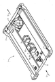
- test device An embodiment of the test device according to the invention is shown in the drawing and will be described below.
- the test device is shown schematically and designated 1 in total. It has the outer shape and the dimensions of a general cargo container, as they are present in large numbers in the system. Visible on the upper shell 2 of the general cargo container, a number of sensors and / or measuring devices are arranged, which are fed by the battery system 3. At the (in the drawing) right end of the shell 2 of the general cargo container, a force sensor system 4 can be seen, which is connected to the below the general cargo container (not shown) to the transport direction 5 of the test device 1 centrally arranged guide roller to those on the guide roller in three levels acting forces while the guide roller is guided in the (not shown) guide rail of the conveyor system.
- the guide roller in the rear area is connected to the speed detection system 6, which is capable of receiving both the direction of rotation, the speed and the acceleration of the guide roller and to the detection unit 7 zuzu meetings.
- the temperature measuring unit 8a, 8b is arranged, which consists of the temperature sensor 8a and the meter 8b.
- a triaxial acceleration sensor is arranged, which detects the acceleration and deceleration values of the test device 1 when driving through the system and thus opens up the possibility of unintentional delays within the system to determine on the basis of the similarly detected location specifically for their causes to research.
- the detection unit 7 is linked to a signal conditioner 10, which converts the measurement signals obtained into storable information that is available after reading the logger.
- a signal conditioner 10 which converts the measurement signals obtained into storable information that is available after reading the logger.
- data known storage media can be used, for example, conventional data storage cards or disk storage can be provided, which can be read out via interfaces and evaluated with suitable software.
- the data logger is configurable for its use, for example, to set the start and end times of the measurement, the measurement intervals, and so on.
- the datalogger can have one or more channels if several sensors are to be connected.
Landscapes
- Control Of Conveyors (AREA)
Claims (19)
- Dispositif de contrôle d'un système de transport de conteneurs de marchandises,
notamment de conteneurs de bagages,
qui peuvent être déplacés sur une voie de convoyage entraînée et sensiblement horizontale par une installation de convoyage à embranchement tout au long,
caractérisé par
au moins une unité ( 1 ) de contrôle, qui est mobile sur la voie de convoyage et dont les dimensions extérieures correspondent sensiblement à celles d'un conteneur de marchandises utilisé dans l'installation de convoyage, et
qui est équipé de divers capteurs et/ou dispositifs ( 4, 6, 8, 9 ) de mesure à des fins de mesures différentes et en des emplacements de mesure différents dans l'installation de convoyage, ainsi que d'un système ( 3 ) d'alimentation en énergie pour les capteurs et/ou les dispositifs ( 4, 6, 8, 9) de mesure. - Dispositif de contrôle d'un système de transport suivant la revendication 1,
caractérisé en ce que
la base de l'unité ( 1 ) de contrôle est un conteneur de marchandises standard,
sur la face inférieure duquel des roues de guidage tournant autour d'un axe vertical pénètrent dans une barre de guidage, qui s'étend entre deux courroies de convoyage, parallèles et portant le conteneur de marchandises, de la voie de convoyage. - Dispositif de contrôle d'un système de transport suivant la revendication 1 et 2,
caractérisé en ce que
sur l'unité ( 1 ) de contrôle est prévue au moins une unité ( 7 ) de détection ayant un enregistrement chronologique de données et un programme de mesure pour la détection et la mémorisation des données de mesure physique obtenues par les capteurs et/ou par les dispositifs ( 4, 6, 8, 9 ) de mesure. - Dispositif de contrôle d'un système de transport suivant la revendication 1 à 3,
caractérisé par
une unité d'acquisition disposée sur l'unité ( 1 ) de contrôle et en amont de l'enregistrement chronologique de données avec une alimentation ( 3 ) en tension des capteurs et/ou des dispositifs ( 4, 6, 8, 9) de mesure. - Dispositif de contrôle d'un système de transport suivant l'une des revendications 1 à 4,
caractérisé en ce que
l'unité d'acquisition et/ou l'enregistrement chronologique de données sont combinés dans l'installation de convoyage à des dispositifs ( 11 ) de localisation des emplacements de mesure. - Dispositif de contrôle d'un système de transport suivant l'une des revendications 1 à 5,
caractérisé par
un système ( 4 ) de capteur de forces, qui est disposé sur l'unité ( 1 ) de contrôle et qui est destiné à la détermination en grandeur et en direction des forces agissant suivant trois axes sur les rouleaux de guidage du conteneur de marchandises lors du parcours de l'installation de convoyage. - Dispositif de contrôle d'un système de transport suivant l'une des revendications 1 à 6,
caractérisé par
un capteur ( 5 ) triaxial d'accélération pour la détermination des forces de l'accélération agissant sur l'unité ( 1 ) de contrôle lors du parcours de l'installation de convoyage. - Dispositif de contrôle d'un système de transport suivant l'une des revendications 1 à 7,
caractérisé par
un système ( 6 ) de détection de vitesse de rotation pour la détermination de la vitesse de rotation, du sens de rotation et de l'accélération en rotation des rouleaux de guidage. - Dispositif de contrôle d'un système de transport suivant l'une des revendications 1 à 8,
caractérisé par
une unité ( 8a. 8b ) de température pour relever la température dans la zone des rouleaux de guidage. - Dispositif de contrôle d'un système de transport suivant la revendication 5,
caractérisé en ce que,
pour la localisation de l'emplacement de mesure, des dispositifs de compteur de trajet sont prévus sur l'unité ( 1 ) de contrôle. - Dispositif de contrôle d'un système de transport suivant la revendication 10,
caractérisé en ce qu'il est prévu, sur l'unité de contrôle, des détections ( 11 ) à spot mobile comme dispositifs de compteur de trajet par lesquelles des zones marquantes de l'installation, dont l'affectation locale est connue, peuvent être reconnues. - Dispositif de contrôle d'un système de transport suivant la revendication 5,
caractérisé en ce qu'il est disposé sur l'unité ( 1 ) de contrôle des indicateurs d'information, qui peuvent être détectés par des appareils de lecture installés dans l'installation. - Dispositif de contrôle d'un système de transport suivant l'une des revendications 1 à 7,
caractérisé en ce qu'une caméra vidéo est installée sur l'unité de contrôle. - Procédé de contrôle d'un système de transport à l'aide d'une unité de contrôle suivant l'une des revendications 1 à 13,
caractérisé en ce que
l'unité de contrôle traverse l'installation de convoyage et détecte ainsi en étant commandée par programme au moins une partie des influences physiques agissant sur l'unité de contrôle ensemble avec l'emplacement de leur mesure et les mémorise pour exploitation ultérieure ou les achemine pour exploitation directe. - Procédé de contrôle d'un système de transport suivant la revendication 14,
caractérisé en ce que,
lorsque l'installation de convoyage est parcourue, les forces d'appui et de guidage s'appliquant orthogonalement aux rouleaux de guidage sont mesurées et sont envoyées à l'unité de détection. - Procédé de contrôle d'un système de transport suivant la revendication 14 et 15,
caractérisé en ce que
les valeurs positives et négatives d'accélération de l'unité de contrôle sont mesurées et mémorisées pendant son passage dans l'installation de convoyage. - Procédé de contrôle d'un système de transport suivant la revendication 14 à 16,
caractérisé en ce que
la vitesse de rotation, le sens de rotation et l'accélération en rotation des rouleaux de guidages sont détectés et mémorisés. - Procédé de contrôle d'un système de transport suivant la revendication 14 à 17,
caractérisé en ce que
pour la détection du trajet de l'unité de contrôle, le nombre des sections de convoyage est détecté par une optique lumineuse et, au moyen des valeurs de compte et de données d'installations mémorisées, une détermination de position de l'unité de contrôle est effectuée dans une unité informatique. - Procédé de contrôle d'un système de transport suivant la revendication 14 à 18,
caractérisé en ce que
l'on mesure la température d'un rouleau de guidage.
Applications Claiming Priority (1)
| Application Number | Priority Date | Filing Date | Title |
|---|---|---|---|
| DE102007011231A DE102007011231A1 (de) | 2007-03-06 | 2007-03-06 | Prüfeinrichtung für ein Transportsystem für Stückgutbehälter |
Publications (2)
| Publication Number | Publication Date |
|---|---|
| EP1967471A1 EP1967471A1 (fr) | 2008-09-10 |
| EP1967471B1 true EP1967471B1 (fr) | 2012-01-11 |
Family
ID=39496147
Family Applications (1)
| Application Number | Title | Priority Date | Filing Date |
|---|---|---|---|
| EP08102026A Not-in-force EP1967471B1 (fr) | 2007-03-06 | 2008-02-26 | Dispositif de contrôle d'un système de transport pour des récipients de marchandises |
Country Status (3)
| Country | Link |
|---|---|
| EP (1) | EP1967471B1 (fr) |
| AT (1) | ATE540885T1 (fr) |
| DE (1) | DE102007011231A1 (fr) |
Families Citing this family (4)
| Publication number | Priority date | Publication date | Assignee | Title |
|---|---|---|---|---|
| DE102009043525A1 (de) * | 2009-09-30 | 2010-10-07 | Siemens Aktiengesellschaft | Prüfeinrichtung für eine Stückgutförderanlage |
| CN108341231B (zh) * | 2018-02-08 | 2019-06-14 | 中国民航大学 | 一种用于机场行李搬运的刚柔混合并联机构 |
| DE102018103421A1 (de) * | 2018-02-15 | 2019-08-22 | Testo SE & Co. KGaA | Datenlogger |
| IT201900002903A1 (it) * | 2019-02-28 | 2020-08-28 | Rexnord Flattop Europe S R L | Metodo e sistema per stimare l’entitá dell’interazione di attrito tra un trasportatore e gli articoli trasportati |
Family Cites Families (2)
| Publication number | Priority date | Publication date | Assignee | Title |
|---|---|---|---|---|
| US3164126A (en) * | 1963-03-22 | 1965-01-05 | Rapids Standard Co Inc | Signal clip |
| US4742931A (en) * | 1987-08-17 | 1988-05-10 | Olympic Plastics, Inc. | Tote box tray |
-
2007
- 2007-03-06 DE DE102007011231A patent/DE102007011231A1/de not_active Withdrawn
-
2008
- 2008-02-26 EP EP08102026A patent/EP1967471B1/fr not_active Not-in-force
- 2008-02-26 AT AT08102026T patent/ATE540885T1/de active
Also Published As
| Publication number | Publication date |
|---|---|
| EP1967471A1 (fr) | 2008-09-10 |
| ATE540885T1 (de) | 2012-01-15 |
| DE102007011231A1 (de) | 2008-09-11 |
Similar Documents
| Publication | Publication Date | Title |
|---|---|---|
| EP1877330B1 (fr) | Procede de surveillance de l'orientation de la bande et/ou du defilement de la bande bandlaufs d'un dispositif transporteur a courroie et dispositif transporteur a courroie | |
| EP2076458B1 (fr) | Dispositif de contrôle d'une installation de transport | |
| EP2037228B1 (fr) | Procédé et dispositif destinés à la détermination d'un intervalle de maintenance d'un véhicule, programme informatique et produit de programme informatique | |
| EP1222126B1 (fr) | Dispositif pour controler une installation de convoyage | |
| EP2171158B1 (fr) | Système et procédé pour analyser des roues de matériel roulant | |
| EP2886494B1 (fr) | Dispositif de transport pour le transport d'objets suspendus | |
| EP1967471B1 (fr) | Dispositif de contrôle d'un système de transport pour des récipients de marchandises | |
| DE102009014251B4 (de) | Behälterförderanlage zum Transportieren von Stückgütern, insbesondere von Gepäckstücken | |
| DE102010044580B4 (de) | Verfahren zum Betreiben einer Etikettiermaschine | |
| DE102009043525A1 (de) | Prüfeinrichtung für eine Stückgutförderanlage | |
| DE4302656C2 (de) | Verfahren und Vorrichtung zum Überprüfen der Funktionsfähigkeit von Inspektionseinrichtungen an Flascheninspektionsmaschinen | |
| DE102011000025A1 (de) | Vorrichtung zum Erfassen von Waren | |
| DE2752193C2 (de) | Transportvorrichtung für Serienerzeugnisse innerhalb einer Wägevorrichtung | |
| EP3810531A1 (fr) | Procédé de détection d'usure et système de transport doté d'une détection d'usure | |
| DE202010017525U1 (de) | Anordnungsstation | |
| EP4286304A1 (fr) | Installation de transport avec contrôle de distribution de produit | |
| EP3433576B1 (fr) | Installation d'inspection pour la vérification optique d'une plaque de verre plane | |
| EP3214423B1 (fr) | Detection precoce d'usure des paliers | |
| EP4263395A1 (fr) | Dispositif de transport doté d'un système de surveillance de fonctionnement | |
| DE102012107847A1 (de) | Kontrollvorrichtung zur Kontrolle des Zustandes einer Förderbandanlage | |
| CN113879799A (zh) | 运输车姿态异常检测装置、方法及货品运输系统 | |
| CN105675629A (zh) | 一种具打标功能的安检机 | |
| DE102012015020A1 (de) | Industrielle Förderanlage und Verfahren zum Betreiben einer solchen | |
| DE202018105927U1 (de) | Detektionsvorrichtung, Leitungswagen und Schleppleitungssystem | |
| EP0949134B1 (fr) | Dispositif pour mesurer sans contact la température des paliers de véhicules sur rails en marche |
Legal Events
| Date | Code | Title | Description |
|---|---|---|---|
| PUAI | Public reference made under article 153(3) epc to a published international application that has entered the european phase |
Free format text: ORIGINAL CODE: 0009012 |
|
| 17P | Request for examination filed |
Effective date: 20080710 |
|
| AK | Designated contracting states |
Kind code of ref document: A1 Designated state(s): AT BE BG CH CY CZ DE DK EE ES FI FR GB GR HR HU IE IS IT LI LT LU LV MC MT NL NO PL PT RO SE SI SK TR |
|
| AX | Request for extension of the european patent |
Extension state: AL BA MK RS |
|
| AKX | Designation fees paid |
Designated state(s): AT BE BG CH CY CZ DE DK EE ES FI FR GB GR HR HU IE IS IT LI LT LU LV MC MT NL NO PL PT RO SE SI SK TR |
|
| GRAP | Despatch of communication of intention to grant a patent |
Free format text: ORIGINAL CODE: EPIDOSNIGR1 |
|
| GRAS | Grant fee paid |
Free format text: ORIGINAL CODE: EPIDOSNIGR3 |
|
| GRAA | (expected) grant |
Free format text: ORIGINAL CODE: 0009210 |
|
| AK | Designated contracting states |
Kind code of ref document: B1 Designated state(s): AT BE BG CH CY CZ DE DK EE ES FI FR GB GR HR HU IE IS IT LI LT LU LV MC MT NL NO PL PT RO SE SI SK TR |
|
| REG | Reference to a national code |
Ref country code: GB Ref legal event code: FG4D Free format text: NOT ENGLISH |
|
| REG | Reference to a national code |
Ref country code: CH Ref legal event code: EP |
|
| REG | Reference to a national code |
Ref country code: AT Ref legal event code: REF Ref document number: 540885 Country of ref document: AT Kind code of ref document: T Effective date: 20120115 |
|
| REG | Reference to a national code |
Ref country code: IE Ref legal event code: FG4D |
|
| REG | Reference to a national code |
Ref country code: DE Ref legal event code: R096 Ref document number: 502008006090 Country of ref document: DE Effective date: 20120315 |
|
| PGFP | Annual fee paid to national office [announced via postgrant information from national office to epo] |
Ref country code: FR Payment date: 20120227 Year of fee payment: 5 |
|
| REG | Reference to a national code |
Ref country code: NL Ref legal event code: VDEP Effective date: 20120111 |
|
| PG25 | Lapsed in a contracting state [announced via postgrant information from national office to epo] |
Ref country code: SI Free format text: LAPSE BECAUSE OF FAILURE TO SUBMIT A TRANSLATION OF THE DESCRIPTION OR TO PAY THE FEE WITHIN THE PRESCRIBED TIME-LIMIT Effective date: 20120111 |
|
| LTIE | Lt: invalidation of european patent or patent extension |
Effective date: 20120111 |
|
| PGFP | Annual fee paid to national office [announced via postgrant information from national office to epo] |
Ref country code: GB Payment date: 20120208 Year of fee payment: 5 Ref country code: DK Payment date: 20120217 Year of fee payment: 5 |
|
| PG25 | Lapsed in a contracting state [announced via postgrant information from national office to epo] |
Ref country code: BG Free format text: LAPSE BECAUSE OF FAILURE TO SUBMIT A TRANSLATION OF THE DESCRIPTION OR TO PAY THE FEE WITHIN THE PRESCRIBED TIME-LIMIT Effective date: 20120411 Ref country code: NO Free format text: LAPSE BECAUSE OF FAILURE TO SUBMIT A TRANSLATION OF THE DESCRIPTION OR TO PAY THE FEE WITHIN THE PRESCRIBED TIME-LIMIT Effective date: 20120411 Ref country code: IS Free format text: LAPSE BECAUSE OF FAILURE TO SUBMIT A TRANSLATION OF THE DESCRIPTION OR TO PAY THE FEE WITHIN THE PRESCRIBED TIME-LIMIT Effective date: 20120511 Ref country code: LT Free format text: LAPSE BECAUSE OF FAILURE TO SUBMIT A TRANSLATION OF THE DESCRIPTION OR TO PAY THE FEE WITHIN THE PRESCRIBED TIME-LIMIT Effective date: 20120111 Ref country code: HR Free format text: LAPSE BECAUSE OF FAILURE TO SUBMIT A TRANSLATION OF THE DESCRIPTION OR TO PAY THE FEE WITHIN THE PRESCRIBED TIME-LIMIT Effective date: 20120111 Ref country code: NL Free format text: LAPSE BECAUSE OF FAILURE TO SUBMIT A TRANSLATION OF THE DESCRIPTION OR TO PAY THE FEE WITHIN THE PRESCRIBED TIME-LIMIT Effective date: 20120111 |
|
| PGFP | Annual fee paid to national office [announced via postgrant information from national office to epo] |
Ref country code: NL Payment date: 20120210 Year of fee payment: 5 |
|
| REG | Reference to a national code |
Ref country code: IE Ref legal event code: FD4D |
|
| BERE | Be: lapsed |
Owner name: SIEMENS A.G. Effective date: 20120228 |
|
| PG25 | Lapsed in a contracting state [announced via postgrant information from national office to epo] |
Ref country code: GR Free format text: LAPSE BECAUSE OF FAILURE TO SUBMIT A TRANSLATION OF THE DESCRIPTION OR TO PAY THE FEE WITHIN THE PRESCRIBED TIME-LIMIT Effective date: 20120412 Ref country code: PL Free format text: LAPSE BECAUSE OF FAILURE TO SUBMIT A TRANSLATION OF THE DESCRIPTION OR TO PAY THE FEE WITHIN THE PRESCRIBED TIME-LIMIT Effective date: 20120111 Ref country code: LV Free format text: LAPSE BECAUSE OF FAILURE TO SUBMIT A TRANSLATION OF THE DESCRIPTION OR TO PAY THE FEE WITHIN THE PRESCRIBED TIME-LIMIT Effective date: 20120111 Ref country code: PT Free format text: LAPSE BECAUSE OF FAILURE TO SUBMIT A TRANSLATION OF THE DESCRIPTION OR TO PAY THE FEE WITHIN THE PRESCRIBED TIME-LIMIT Effective date: 20120511 Ref country code: FI Free format text: LAPSE BECAUSE OF FAILURE TO SUBMIT A TRANSLATION OF THE DESCRIPTION OR TO PAY THE FEE WITHIN THE PRESCRIBED TIME-LIMIT Effective date: 20120111 |
|
| PG25 | Lapsed in a contracting state [announced via postgrant information from national office to epo] |
Ref country code: MC Free format text: LAPSE BECAUSE OF NON-PAYMENT OF DUE FEES Effective date: 20120229 Ref country code: CY Free format text: LAPSE BECAUSE OF FAILURE TO SUBMIT A TRANSLATION OF THE DESCRIPTION OR TO PAY THE FEE WITHIN THE PRESCRIBED TIME-LIMIT Effective date: 20120111 |
|
| REG | Reference to a national code |
Ref country code: CH Ref legal event code: PL |
|
| PG25 | Lapsed in a contracting state [announced via postgrant information from national office to epo] |
Ref country code: SE Free format text: LAPSE BECAUSE OF FAILURE TO SUBMIT A TRANSLATION OF THE DESCRIPTION OR TO PAY THE FEE WITHIN THE PRESCRIBED TIME-LIMIT Effective date: 20120111 Ref country code: CZ Free format text: LAPSE BECAUSE OF FAILURE TO SUBMIT A TRANSLATION OF THE DESCRIPTION OR TO PAY THE FEE WITHIN THE PRESCRIBED TIME-LIMIT Effective date: 20120111 Ref country code: EE Free format text: LAPSE BECAUSE OF FAILURE TO SUBMIT A TRANSLATION OF THE DESCRIPTION OR TO PAY THE FEE WITHIN THE PRESCRIBED TIME-LIMIT Effective date: 20120111 Ref country code: LI Free format text: LAPSE BECAUSE OF NON-PAYMENT OF DUE FEES Effective date: 20120229 Ref country code: IE Free format text: LAPSE BECAUSE OF FAILURE TO SUBMIT A TRANSLATION OF THE DESCRIPTION OR TO PAY THE FEE WITHIN THE PRESCRIBED TIME-LIMIT Effective date: 20120111 Ref country code: CH Free format text: LAPSE BECAUSE OF NON-PAYMENT OF DUE FEES Effective date: 20120229 Ref country code: RO Free format text: LAPSE BECAUSE OF FAILURE TO SUBMIT A TRANSLATION OF THE DESCRIPTION OR TO PAY THE FEE WITHIN THE PRESCRIBED TIME-LIMIT Effective date: 20120111 Ref country code: DK Free format text: LAPSE BECAUSE OF FAILURE TO SUBMIT A TRANSLATION OF THE DESCRIPTION OR TO PAY THE FEE WITHIN THE PRESCRIBED TIME-LIMIT Effective date: 20120111 |
|
| PLBE | No opposition filed within time limit |
Free format text: ORIGINAL CODE: 0009261 |
|
| STAA | Information on the status of an ep patent application or granted ep patent |
Free format text: STATUS: NO OPPOSITION FILED WITHIN TIME LIMIT |
|
| PG25 | Lapsed in a contracting state [announced via postgrant information from national office to epo] |
Ref country code: IT Free format text: LAPSE BECAUSE OF FAILURE TO SUBMIT A TRANSLATION OF THE DESCRIPTION OR TO PAY THE FEE WITHIN THE PRESCRIBED TIME-LIMIT Effective date: 20120111 Ref country code: SK Free format text: LAPSE BECAUSE OF FAILURE TO SUBMIT A TRANSLATION OF THE DESCRIPTION OR TO PAY THE FEE WITHIN THE PRESCRIBED TIME-LIMIT Effective date: 20120111 |
|
| 26N | No opposition filed |
Effective date: 20121012 |
|
| REG | Reference to a national code |
Ref country code: DE Ref legal event code: R119 Ref document number: 502008006090 Country of ref document: DE Effective date: 20120901 |
|
| PG25 | Lapsed in a contracting state [announced via postgrant information from national office to epo] |
Ref country code: BE Free format text: LAPSE BECAUSE OF NON-PAYMENT OF DUE FEES Effective date: 20120228 |
|
| PG25 | Lapsed in a contracting state [announced via postgrant information from national office to epo] |
Ref country code: ES Free format text: LAPSE BECAUSE OF FAILURE TO SUBMIT A TRANSLATION OF THE DESCRIPTION OR TO PAY THE FEE WITHIN THE PRESCRIBED TIME-LIMIT Effective date: 20120422 |
|
| PG25 | Lapsed in a contracting state [announced via postgrant information from national office to epo] |
Ref country code: DE Free format text: LAPSE BECAUSE OF NON-PAYMENT OF DUE FEES Effective date: 20120901 |
|
| PG25 | Lapsed in a contracting state [announced via postgrant information from national office to epo] |
Ref country code: MT Free format text: LAPSE BECAUSE OF FAILURE TO SUBMIT A TRANSLATION OF THE DESCRIPTION OR TO PAY THE FEE WITHIN THE PRESCRIBED TIME-LIMIT Effective date: 20120111 |
|
| GBPC | Gb: european patent ceased through non-payment of renewal fee |
Effective date: 20130226 |
|
| REG | Reference to a national code |
Ref country code: FR Ref legal event code: ST Effective date: 20131031 |
|
| PG25 | Lapsed in a contracting state [announced via postgrant information from national office to epo] |
Ref country code: GB Free format text: LAPSE BECAUSE OF NON-PAYMENT OF DUE FEES Effective date: 20130226 Ref country code: FR Free format text: LAPSE BECAUSE OF NON-PAYMENT OF DUE FEES Effective date: 20130228 |
|
| REG | Reference to a national code |
Ref country code: AT Ref legal event code: MM01 Ref document number: 540885 Country of ref document: AT Kind code of ref document: T Effective date: 20130226 |
|
| PG25 | Lapsed in a contracting state [announced via postgrant information from national office to epo] |
Ref country code: TR Free format text: LAPSE BECAUSE OF FAILURE TO SUBMIT A TRANSLATION OF THE DESCRIPTION OR TO PAY THE FEE WITHIN THE PRESCRIBED TIME-LIMIT Effective date: 20120111 |
|
| PG25 | Lapsed in a contracting state [announced via postgrant information from national office to epo] |
Ref country code: LU Free format text: LAPSE BECAUSE OF NON-PAYMENT OF DUE FEES Effective date: 20120226 Ref country code: AT Free format text: LAPSE BECAUSE OF NON-PAYMENT OF DUE FEES Effective date: 20130226 |
|
| PG25 | Lapsed in a contracting state [announced via postgrant information from national office to epo] |
Ref country code: HU Free format text: LAPSE BECAUSE OF FAILURE TO SUBMIT A TRANSLATION OF THE DESCRIPTION OR TO PAY THE FEE WITHIN THE PRESCRIBED TIME-LIMIT Effective date: 20080226 |