EP1967247B1 - Druckluft-Filter und zugehöriger Adapter - Google Patents
Druckluft-Filter und zugehöriger Adapter Download PDFInfo
- Publication number
- EP1967247B1 EP1967247B1 EP07103403A EP07103403A EP1967247B1 EP 1967247 B1 EP1967247 B1 EP 1967247B1 EP 07103403 A EP07103403 A EP 07103403A EP 07103403 A EP07103403 A EP 07103403A EP 1967247 B1 EP1967247 B1 EP 1967247B1
- Authority
- EP
- European Patent Office
- Prior art keywords
- opening
- section
- filter
- opening cross
- adapter
- Prior art date
- Legal status (The legal status is an assumption and is not a legal conclusion. Google has not performed a legal analysis and makes no representation as to the accuracy of the status listed.)
- Active
Links
Images


Classifications
-
- B—PERFORMING OPERATIONS; TRANSPORTING
- B01—PHYSICAL OR CHEMICAL PROCESSES OR APPARATUS IN GENERAL
- B01D—SEPARATION
- B01D46/00—Filters or filtering processes specially modified for separating dispersed particles from gases or vapours
- B01D46/0002—Casings; Housings; Frame constructions
- B01D46/0005—Mounting of filtering elements within casings, housings or frames
-
- B—PERFORMING OPERATIONS; TRANSPORTING
- B01—PHYSICAL OR CHEMICAL PROCESSES OR APPARATUS IN GENERAL
- B01D—SEPARATION
- B01D46/00—Filters or filtering processes specially modified for separating dispersed particles from gases or vapours
- B01D46/0039—Filters or filtering processes specially modified for separating dispersed particles from gases or vapours with flow guiding by feed or discharge devices
- B01D46/0041—Filters or filtering processes specially modified for separating dispersed particles from gases or vapours with flow guiding by feed or discharge devices for feeding
-
- B—PERFORMING OPERATIONS; TRANSPORTING
- B01—PHYSICAL OR CHEMICAL PROCESSES OR APPARATUS IN GENERAL
- B01D—SEPARATION
- B01D46/00—Filters or filtering processes specially modified for separating dispersed particles from gases or vapours
- B01D46/24—Particle separators, e.g. dust precipitators, using rigid hollow filter bodies
- B01D46/2403—Particle separators, e.g. dust precipitators, using rigid hollow filter bodies characterised by the physical shape or structure of the filtering element
- B01D46/2411—Filter cartridges
-
- B—PERFORMING OPERATIONS; TRANSPORTING
- B01—PHYSICAL OR CHEMICAL PROCESSES OR APPARATUS IN GENERAL
- B01D—SEPARATION
- B01D2201/00—Details relating to filtering apparatus
- B01D2201/29—Filter cartridge constructions
- B01D2201/291—End caps
-
- B—PERFORMING OPERATIONS; TRANSPORTING
- B01—PHYSICAL OR CHEMICAL PROCESSES OR APPARATUS IN GENERAL
- B01D—SEPARATION
- B01D2201/00—Details relating to filtering apparatus
- B01D2201/34—Seals or gaskets for filtering elements
-
- B—PERFORMING OPERATIONS; TRANSPORTING
- B01—PHYSICAL OR CHEMICAL PROCESSES OR APPARATUS IN GENERAL
- B01D—SEPARATION
- B01D2265/00—Casings, housings or mounting for filters specially adapted for separating dispersed particles from gases or vapours
- B01D2265/04—Permanent measures for connecting different parts of the filter, e.g. welding, glueing or moulding
- B01D2265/05—Special adapters for the connection of filters or parts of filters
-
- Y—GENERAL TAGGING OF NEW TECHNOLOGICAL DEVELOPMENTS; GENERAL TAGGING OF CROSS-SECTIONAL TECHNOLOGIES SPANNING OVER SEVERAL SECTIONS OF THE IPC; TECHNICAL SUBJECTS COVERED BY FORMER USPC CROSS-REFERENCE ART COLLECTIONS [XRACs] AND DIGESTS
- Y10—TECHNICAL SUBJECTS COVERED BY FORMER USPC
- Y10T—TECHNICAL SUBJECTS COVERED BY FORMER US CLASSIFICATION
- Y10T29/00—Metal working
- Y10T29/49—Method of mechanical manufacture
- Y10T29/49826—Assembling or joining
Definitions
- the invention relates to a compressed air filter adapter for connecting a filter element to a filter connection housing, wherein the adapter has a flow channel for compressed air enclosed by a wall, wherein the flow channel is bounded at a first end by a first opening and at a second end by a second opening wherein the first opening is provided for connection to a filter port housing and forms a first opening area, and wherein the second opening defines a filter-side opening and forms a second opening area, and a method for connecting a filter element to a filter port housing.
- Filter arrangements for compressed air are known from the prior art, for example from the EP 1 042 043 B1 , well known. Most such compressed air arrangements are used serially in a compressed air flow such that the entire compressed air of the compressed air flow is passed through a filter element. Since the filter element adds to its filter function correspondingly over longer operating times, ie dirt particles are collected within the filter element, it must be replaced at fixed or variable maintenance intervals. In order to facilitate this process of replacing the filter element, the filter element sits in a filter connection housing, wherein the filter connection housing remains firmly connected to the compressed air flow leading line.
- a filter with a multi-part housing has a housing body and a housing head, the housing head having an inlet for a gas flow to be cleaned and an outlet.
- the housing has a filter element comprising an element head and a tubular element body.
- a filter is disclosed which consists of an upper part and a lower part, between which a connecting flange is arranged.
- the upper part has two connection adapters, through which the filter can be inserted, for example, in a compressed air line.
- the object of the present invention is to propose a compressed air filter adapter, which ensures a simple and reliable connection of a filter element to a filter connection housing and at the same time allows a comparatively favorable flow guidance in the filter connection housing.
- a central idea of the present invention is that in the compressed air filter adapter according to the invention first and second openings are offset from one another such that the centroid of the first opening relative to the normal from the centroid of the second opening normal is displaced in a direction of offset and that the first opening cross-section one of the circular shape deviating basic shape, with respect to the offset direction, a constriction and an extension are defined.
- the adapter is configured such that in the projection of the first opening cross-section on the second opening cross-section of the first opening cross-section is partially outside the second opening cross-section.
- the extension in the offset direction (R) and the constriction against the offset direction (R) is formed.
- the idea of the greater free space in the opposite direction of the offset direction is reinforced, since space gain is achieved on the opposite direction of the offset not only by the offset itself but also by the non-rotationally symmetrical design of the first opening cross-section.
- a free space in the filter connection housing can already be obtained by displacing a first opening cross-section which is purely circular in the offset direction.
- a non-rotationally symmetrical design of the first opening cross-section is made, the effect is enhanced.
- the first opening cross-section may have the basic shape of an isosceles triangle, the area facing the apex of the isosceles triangle forming the constriction and the area facing the base the extension of the first opening cross section.
- the first opening cross section has the basic shape of an isosceles triangle, in which the corners are rounded.
- first opening cross section and the second opening cross section are arranged substantially parallel to one another.
- the adapter can be designed as a separate component for connection both to a filter element and to the filter connection housing.
- the adapter can be integrally formed on the filter element and form with this a filter unit.
- the "free space" obtained by the displacement according to the invention and the non-rotationally symmetrical design of the first opening cross section can also be used for other installations, flow channels, etc., in a preferred embodiment Design provided that the adapter is flowed around by entering the filter element or exiting the filter element air flow.
- the wall of the adapter forms an outer flow guide surface or has such a flow guide surface.
- the flow guide surface is formed such that it at least substantially follows the offset between the first opening and the second opening.
- the second opening cross-section is partially outside the first opening cross-section.
- the first opening cross-section is partially outside the second opening cross-section or even in this projection, the second opening cross-section is partially outside the first opening cross-section.
- a peripheral sealing device for producing a fluid-tight seal with respect to the filter connection housing in the case of a filter element inserted in the operating position can be formed on the wall.
- Belonging to the invention is also a filter element comprising a filter element with a flat inlet or outflow surface, wherein the filter element has a cylindrical basic structure, as well as an integrally molded adapter, as described above, to look at.
- a filter assembly comprising a filter connection housing, a filter element and an adapter, as described and claimed herein, wherein the adapter is provided for connection of the filter element to the filter connection housing.
- a method for connecting a filter element to a filter connection housing wherein the filter connection housing has a first flow opening and a second flow opening, wherein an adapter is used to connect the filter element to the filter connection housing, wherein the adapter has a wall enclosed by a flow channel for compressed air , in which the flow channel is bounded at a first end by a first opening and at a second end by a second opening, wherein the first opening is provided for connection to a filter connection housing and forms a first opening cross-section, and wherein the second opening defines a filter-side opening and a second opening cross-section is formed, wherein the first and second openings are offset from each other, such that the centroid of the first opening relative to the center of gravity of the second opening outgoing normal in an offset direction (R) is shifted, wherein the first opening cross section deviates from the circular shape with a basic shape Has constriction and one of the constriction opposite extension, wherein in the projection of the first opening cross-section (16) on the second opening
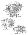
- Fig. 1 an embodiment of a filter assembly according to the invention in an exploded perspective view is shown.
- the filter arrangement initially comprises a filter connection housing 13 with a first flow opening 28 and a second flow opening 29.
- the first flow opening 28 of the filter connection housing 13 can define an inflow opening and the second flow opening 29 of the filter connection housing 13 can define an outflow opening.
- the direction of flow could also be directed in the opposite direction.
- the filter connection housing 13 consists of a main body 30, a cover 31 provided on an upper side 34, and two connecting flanges 32, 33 at the first flow opening 28 and second flow opening 29 for connection to a pressure fluid line or for connecting a further pressure fluid perfused component, for example a further filter element.
- the filter connection housing 13 On a bottom side 35 opposite the top side 34, the filter connection housing 13 has a filter connection opening 36 in order to be able to connect a filter element 12 to the filter connection housing 13 in a pressure fluid tight manner via an adapter 11.
- an interior of the filter connection housing 13 is divided by a downwardly open partition wall 37 into a first chamber 38 and a second chamber 39.
- the first chamber 38 connects to the first flow opening 28.
- the second chamber 39 adjoins the second flow opening 29.
- the first chamber 38 is partially enclosed by the second chamber 39, so that the first chamber 38 could also be referred to as partially enclosed, the second chamber 39 as a partially enclosing chamber.
- the first chamber 38 is open to the underside 35 of the filter connection housing 13, forming a connection opening 40 that is substantially triangular in cross-section.
- the second Chamber 39 is also open on its underside 35 facing the end to form an opening 41.
- the filter element 12 is inserted via the filter adapter port 11 via the filter connection opening 36 in a pressure fluid-tight manner into the filter connection housing 13.
- the adapter 11 has a connection profile 42 corresponding to the connection opening 40 of the first chamber 38.
- the connection profile 42 of the adapter 11 encloses a first opening 14 in the adapter 11, wherein this first opening 14 has a first opening cross section 16 of likewise substantially triangular shape. Both in the triangular configuration of the connection opening 40 and in the substantially triangular configuration of the first opening cross-section 16, there is a substantially equilateral triangle with rounded corners.
- the edge of the adapter 11 forming the connection profile 42 is dimensioned equally over the entire circumference in the present embodiment, the first opening cross section 16 plus the circumferential edge of uniform thickness and a defined insertion tolerance corresponds to the cross section of the connection opening 40 in the filter connection housing 13 the connection profile 42 forming edge of the adapter 11 is still a circumferential sealing device 25 is held in a circumferential groove 53, wherein the sealing means 25 causes a seal between the outside of the connection profile 42 of the adapter 11 and the inner wall of the first chamber 38 in the filter connection housing.
- an anti-rotation device is simultaneously defined in such a way that the filter element 12 can only be used in an exactly predetermined angular position. Due to the offset of the adapter 11 is so far only three possible positioning in spite of the formation of port 40 and connection profile 42 in the form of an equilateral triangle, the adapter 11 and the filter element 12 to be inserted so that the side of the connection profile 42, compared to Center axis of the filter element 12 is furthest away, the first flow opening 28 of the filter connection housing 13 faces.
- the adapter 11 is here permanently connected to the filter element 12, namely fixed directly to the front side on a cylindrical filter casing 43, which at the same time defines an inlet or outflow surface 27 of the filter element 12, here specifically an outflow surface.
- a central channel 44 is provided, from which the pressure fluid passes through the filter materials and exits at the filter casing 43.
- the flow direction could also be reversed, that is, the pressurized fluid could enter the filter jacket 43, flow through the filter media, and be collected in the central channel 44 and discharged from the filter element 12.
- the adapter 11 has a flow channel 21 for the pressurized fluid enclosed by a wall 20. Within the flow channel 21, the pressure fluid is guided from the first opening 14 to a filter-side second opening 15, which defines a second opening cross-section 17.
- First opening 14 and second opening 15 of the adapter 11 are offset from one another, namely such that the centroid of the first opening 14 relative to the normal from the centroid of the second opening 15 normal in an offset direction (R), specifically about an offset of 3 mm 30 mm, preferably from about 10 mm to 20 mm, in particular by about 15 mm, is shifted.
- the triangular opening cross section 16 of the first opening 14 is transferred into the second opening cross section 17 of the second opening 15.
- the second opening cross-section 17 is circular.
- the wall 20 is designed so that the flow channel 21 has an at least substantially the same cross-sectional area over its course.
- the filter element 12 is accommodated in a cylindrical, closed filter cover cap 45 at the end.
- the Filterabdeckkappe 45 can be closed pressure fluid tight with the filter connection housing 13, in particular via a bayonet 46. If a pressurized fluid connection between the filter connection housing 13 and Filterabdeckkappe 45 is made via a bayonet fitting 46, the filter element 12 is rotatably received in the Filterabdeckkappe 45, since it rotates with its connection profile 42 in the first chamber 38 when connecting or inserting to the filter connection housing 13 intervenes.
- a space or vestibule 47 which is aerodynamically advantageous, namely in the specific embodiment ensures an improved outflow of the pressurized fluid from the filter connection housing 13 via the second flow opening 29.
- the pressure fluid emerging from the filter casing 43 and directed back into the filter connection housing 13 in the area of the adapter 11, which defines with its wall 20 on the outside thereof a flow guide surface 22, can be brought together and collected in the direction of the second flow opening 29 ,
- the volume of the antechamber 47 ensures that the pressure fluid can be discharged past the adapter 11 and out of the second flow opening 29 with only a very small flow resistance.
- the filter element 12 is as well as the Filterabdeckkappe 45 of cylindrical shape, preferably of circular cylindrical shape.
- the filter element 12 has a longitudinal central axis, which is aligned orthogonal to the surface normal of the first flow opening 28 and / or the second flow opening 29.
- the centroid of the first opening cross-section 16 of the first opening 14 in the adapter 11 is offset relative to the longitudinal center axis of the filter element 12.
- an extension 19 and counter to the offset direction a narrowing 18 of the first opening cross-section 16 is defined such that as many surface portions relative to the longitudinal central axis of the filter element 12 within the first opening 14 on one side, in particular on the first flow opening 28 side facing be moved.
- the first chamber 38 also has such a geometry offset with respect to a central axis or center plane. Specifically, the first chamber 38 is disposed adjacent the first flow port 28 and extends into a central region of the filter port housing 13. The second chamber 39 is contiguous with the second flow port 29 and extends peripherally, partially enclosing the first chamber 38.
- the first opening cross-section 16 lies partially outside the second opening cross-section 17.
- the second opening cross-section 17 lies partially outside the first opening cross-section 16 in this projection 16 and second opening cross-section 17 are arranged parallel to each other, the projection of the first opening cross-section 16 on the second opening cross-section 17 of course corresponds to the projection of the second opening cross-section 17 on the first opening cross-section sixteenth
- the filter connection housing may also include a venting device 48 with a sealing disc 49, wherein a locking screw 50 is screwed into a bore 51 with a corresponding internal thread, the locking screw 50 simultaneously locks the bayonet fitting 46 such that Filterabdeckkappe 45 and filter connection housing 13 are pressure fluid tightly engaged.
- a connecting bore 52 which can be covered pressure fluid tight at an outer end by the sealing disc 49 and communicates with the interior of the filter connection housing 13, it is ensured that only when the locking screw 50 is tightened and the sealing disc 49 on the connecting hole 52 presses, a pressure in the filter connection housing 13 can build. If the bayonet lock 46 is thus not properly closed, the locking screw 50 can not be screwed in the correct position, so that the connecting bore 52 can not be closed and no pressure can build up in the filter connection housing 13. If, however, the locking screw 50 is screwed in correctly, the bayonet lock 46 is blocked and the connecting bore 52 is closed by the sealing disc 49, so that the filter assembly can be put into operation.
- FIGS. 4 to 6 An alternative embodiment of a filter arrangement according to the invention is in the FIGS. 4 to 6 illustrated.
- the structure of the filter assembly according to the FIGS. 4 to 6 corresponds largely to the structure of the filter assembly according to the FIGS. 1 to 3
- the filter connection housing 13 is formed as an extruded profile.
- the first chamber 38 within the main body 30 of the filter connection housing 13 is initially purely cylindrical, namely formed in a cross-sectional shape of an isosceles triangle with rounded corners, the first chamber 38 is the filter element 12 facing away from directly closed by the lid 31.
- FIGS. 7 and 8 is the one with the filter port housings according to FIGS. 1 to 3 respectively.
- FIGS. 4 to 6 Implementing embodiment of an adapter according to the invention for connecting a filter element illustrated again separately, in this regard to the comments on the FIGS. 1 to 3 is referenced.
- Fig. 9 For illustrative purposes, the effect achieved by the offset of the adapter 11 in the inlet or outflow region of the filter connection housing 13 is illustrated. Assuming a same outer contour of the filter connection housing is in the opposite left the situation according to the prior art, right, however, the enlargement of the second chamber 39 achieved by the displacement of the first chamber 38 in the direction of the first flow opening 28 illustrated. In the case of the specifically proposed offset of the centroid of the connection opening 40 of the first chamber 38 from a central position aligned with the longitudinal center axis back to the first flow opening 28 by 15 mm, the cross section of the second chamber along the longitudinal center plane through the first flow opening 28 and second flow opening 29th increase to 126%.
- connection opening 40 of the first chamber 38 is displaced in the direction of the first flow opening 28. Due to the additional asymmetrical design, the offset has a particularly effective effect.
Description
- Die Erfindung betrifft einen Druckluftfilter-Adapter zum Anschluss eines Filterelements an ein Filteranschlussgehäuse, wobei der Adapter einen durch eine Wandung umschlossenen Strömungskanal für Druckluft aufweist, wobei der Strömungskanal an einem ersten Ende durch eine erste Öffnung und an einem zweiten Ende durch eine zweite Öffnung begrenzt wird, wobei die erste Öffnung zum Anschluss an ein Filteranschlussgehäuse vorgesehen ist und einen ersten Öffnungsquerschnitt ausbildet, und wobei die zweite Öffnung eine filterseitige Öffnung definiert und einen zweiten Öffnungsquerschnitt ausbildet, sowie ein Verfahren zum Anschließen eines Filterelements an ein Filteranschlussgehäuse.
- Filteranordnungen für Druckluft sind aus dem Stand der Technik, beispielsweise aus der
EP 1 042 043 B1 , hinlänglich bekannt. Meist werden derartige Druckluftanordnungen seriell in einen Druckluftstrom eingesetzt derart, dass die gesamte Druckluft des Druckluftstromes über ein Filterelement geführt wird. Da das Filterelement seiner Filterfunktion entsprechend über längere Betriebszeiten zusetzt, also Schmutzpartikel innerhalb des Filterelements aufgefangen werden, muss es in festgelegten oder variablen Wartungsintervallen ersetzt werden. Um diesen Prozess des Ersetzens des Filterelements zu erleichtern, sitzt das Filterelement in einem Filteranschlussgehäuse, wobei das Filteranschlussgehäuse fest mit der den Druckluftstrom führenden Leitung verbunden bleibt. - Allerdings können im Filteranschlussgehäuse aufgrund der verschiedenen Zielsetzungen, nämlich raumsparender Einbau in die zu filternde Druckluft führende Leitung, Zugänglichkeit, des Filterelements, sowie zuverlässige Abdichtung zwischen Filterelement und Filteranschlussgehäuse beengte Strömungsverhältnisse entstehen.
- In der
DE 100 52 524 A1 ist ein Filter mit einem mehrteiligen Gehäuse offenbart. Das Gehäuse weist einen Gehäusekörper und einen Gehäusekopf auf, wobei der Gehäusekopf einen Einlass für einen zu reinigenden Gasstrom und einen Auslass hat. Das Gehäuse weist ein Filterelement auf, das einen Elementkopf und einen rohrförmigen Elementkörper aufweist. In derDE 103 09 428 A1 ist ein Filter offenbart, der aus einem Oberteil und einem Unterteil besteht, zwischen denen ein Anschlussflansch angeordnet ist. Das Oberteil besitzt zwei Anschlussadapter, über die sich der Filter beispielsweise in eine Druckluftleitung einfügen lässt. - Die Aufgabe der vorliegenden Erfindung besteht darin, einen Druckluftfilter-Adapter vorzuschlagen, der einen einfachen und zuverlässigen Anschluss eines Filterelements an ein Filteranschlussgehäuse gewährleistet und gleichzeitig eine vergleichsweise günstige Strömungsführung im Filteranschlussgehäuse ermöglicht.
- Diese Aufgabe wird mit einem Druckluftfilter-Adapter nach den Merkmalen des Anspruches 1 gelöst.
- Vorteilhafte Weiterbildungen sind in den Unteransprüchen angegeben.
- Ein Kerngedanke der vorliegenden Erfindung besteht darin, dass beim erfindungsgemäßen Druckluftfilter-Adapter erste und zweite Öffnung derart zueinander versetzt sind, dass der Flächenschwerpunkt der ersten Öffnung gegenüber der vom Flächenschwerpunkt der zweiten Öffnung ausgehenden Normalen in eine Versatzrichtung verschoben ist und dass der erste Öffnungsquerschnitt eine von der Kreisform abweichende Grundform aufweist, wobei bezogen auf die Versatzrichtung eine Verengung sowie eine Erweiterung definiert sind. Der Adapter ist so ausgestaltet, dass in der Projektion des ersten Öffnungsquerschnittes auf den zweiten Öffnungsquerschnitt der erste Öffnungsquerschnitt teilweise außerhalb des zweiten Öffnungsquerschnittes liegt.
- Vorteilhafte Weiterbildungen sind in den Unteransprüchen angegeben.
- Durch die versetzte Anordnung der Öffnungen sowie die nicht rotationssymmetrische Ausbildung des ersten Öffnungsquerschnitts wird erreicht, dass im Filteranschlussgehäuse auf der der Versatzrichtung entgegenliegenden Seite Freiraum gewonnen wird, der strömungstechnisch und/oder für weitere Einbauten genutzt werden kann.
- In einer bevorzugten Ausgestaltung ist die Erweiterung in Versatzrichtung (R) und die Verengung entgegen der Versatzrichtung (R) ausgebildet. Insofern wird der Gedanke des größeren Freiraums in der der Versatzrichtung entgegengesetzten Richtung noch verstärkt, da Raumgewinn auf der der Versatzrichtung entgegenliegenden Seite nicht nur durch den Versatz selbst sondern auch durch die nicht rotationssymmetrische Ausbildung des ersten Öffnungsquerschnitts erzielt wird.
- Gemäß einem Grundgedanken der vorliegenden Erfindung, der auch unabhängig von der nicht rotationssymmetrische Ausbildung des ersten Öffnungsquerschnitts beansprucht wird, ist ein Freiraum im Filteranschlussgehäuse bereits dadurch zu gewinnen, dass ein rein in Kreisform vorliegender erster Öffnungsquerschnitt in Versatzrichtung versetzt wird. Dadurch, dass zusätzlich eine nicht rotationssymmetrische Ausbildung des ersten Öffnungsquerschnitts vorgenommen wird, wird der Effekt noch verstärkt.
- In einer ersten konkreten Ausgestaltung kann der erste Öffnungsquerschnitt die Grundform eines gleichschenkligen Dreiecks aufweisen, wobei der der Spitze des gleichschenkligen Dreiecks zugewandte Bereich die Verengung und der der Basis zugewandte Bereich die Erweiterung des ersten Öffnungsquerschnitts ausbilden.
- In einer konkretisierten Ausgestaltung weist dabei der erste Öffnungsquerschnitt die Grundform eines gleichschenkligen Dreiecks auf, bei dem die Ecken gerundet ausgebildet sind.
- In einer konkreten, bevorzugten Ausgestaltung sind erster Öffnungsquerschnitt und zweiter Öffnungsquerschnitt im Wesentlichen parallel zueinander angeordnet.
- In einer ersten möglichen Ausführungsform kann der Adapter als separates Bauteil zum Anschluss sowohl an ein Filterelement als auch an das Filteranschlussgehäuse ausgebildet sein.
- In einer alternativen Ausführungsform kann der Adapter integral an das Filterelement angeformt sein und mit diesem eine Filtereinheit ausbilden.
- Obwohl der durch den erfindungsgemäßen Versatz sowie die nicht rotationssymmetrische Ausbildung des ersten Öffnungsquerschnitts gewonnene "Freiraum" auch für andere Einbauten, Strömungskanäle, etc. genutzt werden kann, ist in einer bevorzugten Ausgestaltung vorgesehen, dass der Adapter vom in das Filterelement eintretenden bzw. vom Filterelement austretenden Luftstrom umströmt wird. In dieser konkreten Ausgestaltung bildet die Wandung des Adapters eine außenliegende Strömungsleitfläche aus bzw. weist eine solche Strömungsleitfläche auf.
- In einer bevorzugten Ausgestaltung ist die Strömungsleitfläche so ausgebildet, dass sie dem Versatz zwischen erster Öffnung und zweiter Öffnung zumindest im Wesentlichen folgt.
- Weiter kann vorgesehen sein, dass in dieser Projektion auch der zweite Öffnungsquerschnitt teilweise außerhalb des ersten Öffnungsquerschnittes liegt.
- Schließlich kann auch vorgesehen sein, dass in der Projektion des zweiten Öffnungsquerschnittes auf den ersten Öffnungsquerschnitt der erste Öffnungsquerschnitt teilweise außerhalb des zweiten Öffnungsquerschnittes liegt bzw. auch in dieser Projektion der zweite Öffnungsquerschnitt teilweise außerhalb des ersten Öffnungsquerschnitts liegt.
- Weiter kann beim erfindungsgemäßen Adapter an der Wandung eine umlaufende Dichteinrichtung zur Herstellung einer fluiddichten Abdichtung gegenüber dem Filteranschlussgehäuse bei in Betriebsposition eingesetztem Filterelement ausgebildet sein.
- Zur Erfindung gehörig ist auch ein Filterelement umfassend ein Filterelement mit einer flächigen Ein- bzw. Ausströmfläche, wobei das Filterelement eine zylindrische Grundstruktur aufweist, sowie einem integral angeformten Adapter, wie vorstehend beschrieben, anzusehen.
- Weiter wird auch eine Filteranordnung beansprucht umfassend ein Filteranschlussgehäuse, ein Filterelement sowie einen Adapter, wie hier beschrieben und beansprucht, wobei der Adapter zum Anschluss des Filterelements an das Filteranschlussgehäuse vorgesehen ist.
- Schließlich wird ein Verfahren zum Anschließen eines Filterelements an ein Filteranschlussgehäuse beansprucht, wobei das Filteranschlussgehäuse eine erste Strömungsöffnung sowie eine zweite Strömungsöffnung aufweist, wobei ein Adapter zum Anschluss des Filterelements an das Filteranschlussgehäuse verwendet wird, wobei der Adapter einen durch eine Wandung umschlossenen Strömungskanal für Druckluft aufweist, wobei der Strömungskanal an einem ersten Ende durch eine erste Öffnung und an einem zweiten Ende durch eine zweite Öffnung begrenzt wird, wobei die erste Öffnung zum Anschluss an ein Filteranschlussgehäuse vorgesehen ist und einen ersten Öffnungsquerschnitt ausbildet, und wobei die zweite Öffnung eine filterseitige Öffnung definiert und einen zweiten Öffnungsquerschnitt ausbildet, wobei erste und zweite Öffnung zueinander versetzt sind, derart dass der Flächenschwerpunkt der ersten Öffnung gegenüber der vom Flächenschwerpunkt der zweiten Öffnung ausgehenden Normalen in eine Versatzrichtung (R) verschoben ist, wobei der erste Öffnungsquerschnitt eine von der Kreisform abweichende Grundform mit einer Verengung und einer der Verengung gegenüberliegenden Erweiterung aufweist, wobei in der Projektion des ersten Öffnungsquerschnitts (16) auf den zweiten Öffnungsquerschnitt (17) der erste Öffnungsquerschnitt teilweise außerhalb des zweiten Öffnungsquerschnitts (17) liegt, und wobei das Filterelement über einen Adapter druckfluiddicht mit dem Filteranschlussgehäuse derart verbunden wird, dass der Strömungsweg von der ersten Strömungsöffnung zur zweiten Strömungsöffnung über das Filterelement geführt ist.
- Die Erfindung wird nachstehend auch hinsichtlich weiterer Merkmale und Vorteile anhand der Beschreibung von Ausführungsbeispielen und unter Bezugnahme auf die beiliegenden Zeichnungen näher erläutert. Hierbei zeigen:
- Fig. 1
- eine erste Ausführungsform einer erfindungsgemäßen Filteranordnung in perspektivischer Explosionsansicht
- Fig. 2
- eine Schnittansicht durch die Filteranordnung nach
Fig. 1 entlang der Linie II II inFig. 3 - Fig. 3
- eine Schnittansicht der Filteranordnung nach
Fig. 1 entlang der Linie III III inFig. 2 - Fig. 4
- eine zweite Ausführungsform der erfindungsgemäßen Filteranordnung in perspektivischer Explosionsansicht
- Fig. 5
- eine Schnittansicht durch die Filteranordnung nach
Fig. 4 entlang der Linie V V inFig. 6 - Fig. 6
- eine Schnittansicht der Filteranordnung nach
Fig. 4 entlang der Linie VI VI inFig. 5 - Fig. 7
- eine Schnittansicht durch eine Ausführungsform eines erfindungsgemäßen Adapters
- Fig. 8
- eine perspektivische Ansicht der Ausführungsform des erfindungsgemäßen Adapters nach
Fig. 7 - Fig. 9
- eine Prinzipansicht zur Veranschaulichung des durch den Versatz erreichten Effekts bei einem Filteranschlussgehäuse mit gleichen Außenkonturen
- In
Fig. 1 ist eine Ausführungsform einer erfindungsgemäßen Filteranordnung in perspektivischer Explosionsansicht dargestellt. Die Filteranordnung umfasst zunächst ein Filteranschlussgehäuse 13 mit einer ersten Strömungsöffnung 28 und einer zweiten Strömungsöffnung 29. In einer konkreten Ausgestaltung kann die erste Strömungsöffnung 28 des Filteranschlussgehäuses 13 eine Einströmöffnung und die zweite Strömungsöffnung 29 des Filteranschlussgehäuses 13 eine Ausströmöffnung definieren. Die Durchströmungsrichtung könnte allerdings auch entgegengesetzt gerichtet sein. - Das Filteranschlussgehäuse 13 besteht in der vorliegenden Ausführungsform aus einem Grundkörper 30, einem an einer Oberseite 34 vorgesehenen Deckel 31, sowie zwei Anschlussflanschen 32, 33 an der ersten Strömungsöffnung 28 bzw. zweiten Strömungsöffnung 29 zum Anschluss in eine Druckfluidleitung bzw. zum Anschluss einer weiteren Druckfluid durchströmten Komponente, beispielsweise einem weiteren Filterelement.
- An einer der Oberseite 34 gegenüberliegenden Unterseite 35 weist das Filteranschlussgehäuse 13 eine Filteranschlussöffnung 36 auf, um über einen Adapter 11 ein Filterelement 12 druckfluiddicht an das Filteranschlussgehäuse 13 anschließen zu können.
- Zu diesem Zweck ist ein Innenraum des Filteranschlussgehäuses 13 durch eine nach unten offene Trennwand 37 in eine erste Kammer 38 sowie eine zweite Kammer 39 unterteilt. Dabei schließt sich die erste Kammer 38 an die erste Strömungsöffnung 28 an. Die zweite Kammer 39 schließt sich hingegen an die zweite Strömungsöffnung 29 an. Die erste Kammer 38 wird dabei von der zweiten Kammer 39 teilweise umschlossen, so dass die erste Kammer 38 auch als teilweise umschlossene, die zweite Kammer 39 als teilweise umschließende Kammer bezeichnet werden könnte. Die erste Kammer 38 ist der Unterseite 35 des Filteranschlussgehäuses 13 zugewandt offen unter Ausbildung einer im Querschnitt im wesentlichen dreieckförmigen Anschlussöffnung 40 ausgebildet. Die zweite Kammer 39 ist an ihrem der Unterseite 35 zugewandten Ende ebenfalls unter Ausbildung einer Öffnung 41 offen ausgebildet.
- Das Filterelement 12 wird über dem bereits erwähnten Adapter 11 über die Filteranschlussöffnung 36 druckfluiddicht in das Filteranschlussgehäuse 13 eingesetzt. Hierzu weist der Adapter 11 ein der Anschlussöffnung 40 der ersten Kammer 38 entsprechendes Anschlussprofil 42 auf. Das Anschlussprofil 42 des Adapters 11 umschließt dabei eine erste Öffnung 14 im Adapter 11, wobei diese erste Öffnung 14 einen ersten Öffnungsquerschnitt 16 von ebenfalls im Wesentlichen dreiecksförmiger Gestalt aufweist. Sowohl bei der dreiecksförmigen Gestaltung der Anschlussöffnung 40 als auch bei der im Wesentlichen dreiecksförmigen Gestaltung des ersten Öffnungsquerschnittes 16 liegt ein im wesentlichen gleichseitiges Dreieck mit abgerundeten Ecken vor. Da der das Anschlussprofil 42 ausbildende Rand des Adapters 11 über den gesamten Umfang bei der vorliegenden Ausführungsform gleich stark bemessen ist, entspricht der erste Öffnungsquerschnitt 16 zuzüglich des umlaufenden Randes einheitlicher Stärke und einer definierten Einschubtoleranz dem Querschnitt der Anschlussöffnung 40 im Filteranschlussgehäuse 13. Außen an dem das Anschlussprofil 42 ausbildenden Rand des Adapters 11 ist noch eine umlaufende Dichteinrichtung 25 in einer umlaufenden Nut 53 gehalten, wobei die Dichteinrichtung 25 eine Abdichtung zwischen der Außenseite des Anschlussprofils 42 des Adapters 11 und der Innenwandung der ersten Kammer 38 im Filteranschlussgehäuse bewirkt.
- Durch die dreiecksförmige Gestaltung der Anschlussöffnung 40 sowie des Anschlussprofils 42 des Adapters 11 wird gleichzeitig eine Verdrehsicherung dergestalt definiert, dass das Filterelement 12 nur in exakt vorgegebener Winkelposition eingesetzt werden kann. Aufgrund des Versatzes des Adapters 11 ist es mit insofern zunächst drei Positioniermöglichkeiten nur möglich trotz der Ausbildung von Anschlussöffnung 40 und Anschlussprofil 42 in Gestalt eines gleichseitigen Dreiecks den Adapter 11 bzw. das Filterelement 12 so einzusetzen, dass die Seite des Anschlussprofils 42, die gegenüber der Mittelachse des Filterelements 12 am weitesten entfernt liegt, der ersten Strömungsöffnung 28 des Filteranschlussgehäuses 13 zugewandt ist.
- Unter Bezugnahme auf die
Fig. 1 bis 3 wird nun die Gestaltung der hier vorliegenden Ausführungsform des Adapters 11 im Einzelnen besprochen. - Der Adapter 11 ist hier mit dem Filterelement 12 dauerhaft verbunden, nämlich direkt stirnseitig an einem zylinderförmigen Filtermantel 43 befestigt, der gleichzeitig eine Ein- bzw. Ausströmfläche 27 des Filterelements 12, hier konkret eine Ausströmfläche definiert. Innerhalb des Filterelements 12 ist ein zentraler Kanal 44 vorgesehen, von dem aus das Druckfluid die Filtermaterialien durchtritt und am Filtermantel 43 austritt.
- In einer alternativen Ausführungsform könnte die Strömungsrichtung auch umgekehrt sein, das heißt das Druckfluid könnte am Filtermantel 43 eintreten, die Filtermaterialien durchströmen und im zentralen Kanal 44 gesammelt und aus dem Filterelement 12 ausgeführt werden.
- Der Adapter 11 weist einen durch eine Wandung 20 umschlossenen Strömungskanal 21 für das Druckfluid auf. Innerhalb des Strömungskanals 21 wird das Druckfluid von der ersten Öffnung 14 an eine filterseitige zweite Öffnung 15 geführt, die einen zweiten Öffnungsquerschnitt 17 definiert. Erste Öffnung 14 und zweite Öffnung 15 des Adapters 11 sind gegeneinander versetzt, nämlich so, dass der Flächenschwerpunkt der ersten Öffnung 14 gegenüber der vom Flächenschwerpunkt der zweiten Öffnung 15 ausgehenden Normalen in eine Versatzrichtung (R), konkret etwa um einen Versatz von 3 mm bis 30 mm, bevorzugt etwa von 10 mm bis 20 mm, insbesondere um etwa 15 mm, verschoben ist.
- Über die den Strömungskanal 21 definierende Wandung 20 wird der dreiecksförmige Öffnungsquerschnitt 16 der ersten Öffnung 14 in den zweiten Öffnungsquerschnitt 17 der zweiten Öffnung 15 überführt. Bei der hier konkret dargestellten Ausführungsform ist der zweite Öffnungsquerschnitt 17 kreisförmig ausgebildet. Weiter ist die Wandung 20 so gestaltet, dass der Strömungskanal 21 über seinen Verlauf eine zumindest im Wesentlichen gleiche Querschnittsfläche aufweist.
- Das Filterelement 12 ist in einer zylinderförmigen, endseitig geschlossenen Filterabdeckkappe 45 aufgenommen. Die Filterabdeckkappe 45 lässt sich druckfluiddicht mit dem Filteranschlussgehäuse 13, insbesondere über einen Bajonettverschluss 46 verschließen. Sofern eine druckfluide Verbindung zwischen Filteranschlussgehäuse 13 und Filterabdeckkappe 45 über einen Bajonettverschluss 46 vorgenommen wird, ist das Filterelement 12 drehbeweglich in der Filterabdeckkappe 45 aufgenommen, da es beim An- bzw. Einsetzen an das Filteranschlussgehäuse 13 drehfest mit seinem Anschlussprofil 42 in die erste Kammer 38 eingreift.
- Wie insbesondere aus
Fig. 2 erkennbar wird, wird durch den Versatz des Adapters 11 in Richtung auf die erste Strömungsöffnung 28 an der gegenüberliegenden Seite, konkret in dem an die zweite Strömungsöffnung 29 angrenzenden Bereich ein Freiraum bzw. Vorraum 47 geschaffen, der strömungstechnisch vorteilhaft ist, nämlich bei der konkreten Ausführungsform ein verbessertes Ausströmen des Druckfluids aus dem Filteranschlussgehäuse 13 über die zweite Strömungsöffnung 29 gewährleistet. Konkret kann das aus dem Filtermantel 43 austretende innerhalb der Filterabdeckkappe 45 in Richtung auf das Filteranschlussgehäuse 13 zurückgeführte Druckfluid im Bereich des Adapters 11, der mit seiner Wandung 20 an deren Außenseite eine Strömungsleitfläche 22 definiert, zusammengeführt und in Richtung auf die zweite Strömungsöffnung 29 gesammelt werden. Das Volumen des Vorraums 47 gewährleistet, dass das Druckfluid mit nur sehr geringem Strömungswiderstand am Adapter 11 vorbei und aus der zweiten Strömungsöffnung 29 ausgeleitet werden kann. - Es wird somit eine Filteranordnung mit geringen Strömungsverlusten im Ein- und Ausströmbereich umfassend das beschriebene Filterelement 12, die Filterabdeckkappe 45, das Filteranschlussgehäuse 13 sowie den Adapter 11 zur Verbindung von Filterelement 12 und Filteranschlussgehäuse 13 vorgeschlagen. Das Filterelement 12 ist dabei wie auch die Filterabdeckkappe 45 von zylindrischer Gestalt, vorzugsweise von kreiszylindrischer Gestalt. Das Filterelement 12 weist eine Längsmittelachse auf, die orthogonal zur Flächennormalen der ersten Strömungsöffnung 28 und/oder der zweiten Strömungsöffnung 29 ausgerichtet ist. Der Flächenschwerpunkt des ersten Öffnungsquerschnitts 16 der ersten Öffnung 14 im Adapter 11 liegt gegenüber der Längsmittelachse des Filterelements 12 versetzt. In Versatzrichtung ist eine Erweiterung 19 und entgegen der Versatzrichtung eine Verengung 18 des ersten Öffnungsquerschnittes 16 definiert derart, dass möglichst viele Flächenanteile gegenüber der Längsmittelachse des Filterelements 12 innerhalb der ersten Öffnung 14 auf eine Seite hin, insbesondere auf die der ersten Strömungsöffnung 28 zugewandte Seite hin verschoben werden. Entsprechend weist auch die erste Kammer 38 eine solche gegenüber einer Mittelachse bzw. Mittelebene versetzte Geometrie auf. Konkret ist die erste Kammer 38 angrenzend an die erste Strömungsöffnung 28 angeordnet und erstreckt sich in einen zentralen Bereich des Filteranschlussgehäuses 13. Die zweite Kammer 39 ist der zweiten Strömungsöffnung 29 angrenzend ausgebildet und erstreckt sich peripher, die erste Kammer 38 teilweise umschließend.
- Wie sich insbesondere aus
Fig. 3 ergibt, liegt in der Projektion des ersten Öffnungsquerschnittes 16 auf den zweiten Öffnungsquerschnitt 17 der erste Öffnungsquerschnitt 16 teilweise außerhalb des zweiten Öffnungsquerschnittes 17. Gleichzeitig liegt in dieser Projektion auch der zweite Öffnungsquerschnitt 17 teilweise außerhalb des ersten Öffnungsquerschnittes 16. Da bei der konkreten Ausführungsform erster Öffnungsquerschnitt 16 und zweiter Öffnungsquerschnitt 17 parallel zueinander angeordnet sind, entspricht die Projektion des ersten Öffnungsquerschnittes 16 auf den zweiten Öffnungsquerschnitt 17 natürlich der Projektion des zweiten Öffnungsquerschnittes 17 auf den ersten Öffnungsquerschnitt 16. - Das Filteranschlussgehäuse kann noch eine Entlüftungsvorrichtung 48 mit einer abdichtenden Scheibe 49 umfassen, wobei eine Sicherungsschraube 50 in einer Bohrung 51 mit entsprechendem Innengewinde einschraubbar ist, wobei die Sicherungsschraube 50 gleichzeitig den Bajonettverschluss 46 derart sperrt, dass Filterabdeckkappe 45 und Filteranschlussgehäuse 13 druckfluiddicht im Eingriff stehen.
- Über eine Verbindungsbohrung 52, die an einem äußeren Ende durch die abdichtende Scheibe 49 druckfluiddicht überdeckt werden kann und mit dem Innenraum des Filteranschlussgehäuses 13 kommuniziert, wird sichergestellt, dass sich erst dann, wenn die Sicherungsschraube 50 angezogen ist und die abdichtende Scheibe 49 auf die Verbindungsbohrung 52 drückt, ein Druck im Filteranschlussgehäuse 13 aufbauen kann. Ist der Bajonettverschluss 46 somit nicht korrekt verschlossen, kann die Sicherungsschraube 50 nicht in korrekter Position eingeschraubt werden, so dass die Verbindungsbohrung 52 nicht verschlossen werden kann und sich im Filteranschlussgehäuse 13 kein Druck aufbauen lässt. Ist hingegen die Sicherungsschraube 50 korrekt eingeschraubt, wird der Bajonettverschluss 46 blockiert und die Verbindungsbohrung 52 durch die abdichtende Scheibe 49 verschlossen, so dass die Filteranordnung in Betrieb gesetzt werden kann.
- Eine alternative Ausführungsform einer erfindungsgemäßen Filteranordnung ist in den
Figuren 4 bis 6 veranschaulicht. Der Aufbau der Filteranordnung nach denFiguren 4 bis 6 entspricht weitestgehend dem Aufbau der Filteranordnung nach denFiguren 1 bis 3 , wobei allerdings das Filteranschlussgehäuse 13 als Strangpressprofil ausgebildet ist. Insofern ist die erste Kammer 38 innerhalb des Grundkörpers 30 des Filteranschlussgehäuses 13 zunächst rein zylindrisch, nämlich in einer Querschnittsform eines gleichschenkligen Dreiecks mit abgerundeten Ecken ausgebildet, wobei die erste Kammer 38 dem Filterelement 12 abgewandt direkt durch den Deckel 31 verschlossen ist. - In den
Figuren 7 und 8 ist die bei den Filteranschlussgehäusen gemäß denFiguren 1 bis 3 bzw.Figuren 4 bis 6 zum Einsatz gelangende Ausführungsform eines erfindungsgemäßen Adapters zum Anschluss eines Filterelements nochmals separat veranschaulicht, wobei diesbezüglich auf die Ausführungen zu denFiguren 1 bis 3 verwiesen wird. - In
Fig. 9 ist zu Veranschaulichungszwecken der durch den Versatz des Adapters 11 erreichte Effekt im Ein- bzw. Ausströmbereich des Filteranschlussgehäuses 13 veranschaulicht. Unter Annahme einer gleichen Außenkontur des Filteranschlussgehäuses ist in der Gegenüberstellung links die Situation nach dem Stand der Technik, rechts dagegen die durch den Versatz der ersten Kammer 38 in Richtung auf die erste Strömungsöffnung 28 erzielte Vergrößerung der zweiten Kammer 39 veranschaulicht. Bei dem konkret vorgeschlagenen Versatz des Flächenschwerpunktes der Anschlussöffnung 40 der ersten Kammer 38 aus einer zentralen auf die Längsmittelachse ausgerichtete Position zurück auf die erste Strömungsöffnung 28 um 15 mm lässt sich der Querschnitt der zweiten Kammer entlang der Längsmittelebene durch die erste Strömungsöffnung 28 und zweite Strömungsöffnung 29 auf 126% erhöhen. Es wird somit mehr als ein Viertel der ursprünglichen Querschnittsfläche hinzugewonnen. Dieser Effekt beruht darauf, dass die Anschlussöffnung 40 der ersten Kammer 38 in Richtung auf die erste Strömungsöffnung 28 verschoben wird. Durch die zusätzlich asymmetrische Ausgestaltung wirkt sich der Versatz besonders effektiv aus. - Wie aus der Gegenüberstellung in
Fig. 9 erkennbar werden die den Differenzdruck wesentlich mitbeeinflussenden "engsten Stellen" E1 sowie E2 deutlich entschärft. -
- 11
- Adapter
- 12
- Filterelement
- 13
- Filteranschlussgehäuse
- 14
- erste Öffnung
- 15
- zweite Öffnung (filterseitig)
- 16
- erster Öffnungsquerschnitt
- 17
- zweiter Öffnungsquerschnitt
- 18
- Verengung
- 19
- Erweiterung
- 20
- Wandung
- 21
- Strömungskanal
- 22
- Strömungsleitfläche
- 25
- Dichteinrichtung
- 27
- Ein- bzw. Auströmfläche
- 28
- erste Strömungsöffnung (Filteranschlussgehäuse)
- 29
- zweite Strömungsöffnung (Filteranschlussgehäuse)
- 30
- Grundkörper
- 31
- Deckel
- 32, 33
- Anschlussflansche
- 34
- Oberseite
- 35
- Unterseite
- 36
- Filteranschlussöffnung
- 37
- Trennwand
- 38
- erste Kammer
- 39
- zweite Kammer
- 40
- Anschlussöffnung (erste Kammer)
- 41
- Öffnung (zweite Kammer)
- 42
- Anschlussprofil
- 43
- Filtermantel
- 44
- Kanal
- 45
- Filterabdeckkappe
- 46
- Bajonettverschluss
- 47
- Vorraum
- 48
- Entlüftungsvorrichtung
- 49
- abdichtende Scheibe
- 50
- Sicherungsschraube
- 51
- Bohrung
- 52
- Verbindungsbohrung
- 53
- Nut (Dichteinrichtung)
Claims (16)
- Druckluftfilter-Adapter zum Anschluss eines Filterelements (12) an ein Filteranschlussgehäuse (13),- wobei der Adapter (11) einen durch eine Wandung (20) umschlossenen Strömungskanal (21) für Druckluft aufweist,- wobei der Strömungskanal (21) an einem ersten Ende durch eine erste Öffnung (14) und an einem zweiten Ende durch eine zweite Öffnung (15) begrenzt wird,- wobei die erste Öffnung (14) zum Anschluss an ein Filteranschlussgehäuse (13) vorgesehen ist und einen Öffnungsquerschnitt (16) ausbildet, und- wobei die zweite Öffnung (15) eine filterseitige Öffnung definiert und einen zweiten Öffnungsquerschnitt (17) ausbildet,- wobei erste und zweite Öffnung (14, 15) zueinander versetzt sind, derart dass der Flächenschwerpunkt der ersten Öffnung (14) gegenüber der vom Flächenschwerpunkt der zweiten Öffnung (15) ausgehenden Normalen in eine Versatzrichtung (R) verschoben ist,- und wobei der erste Öffnungsquerschnitt (16) eine von der Kreisform abweichende Grundform aufweist,
wobei bezogen auf die Versatzrichtung (R) eine Verengung (18) sowie eine Erweiterung (19) definiert sind,
wobei in der Projektion des ersten Öffnungsquerschnitts (16) auf den zweiten Öffnungsquerschnitt (17) der erste Öffnungsquerschnitt (16) teilweise außerhalb des zweiten Öffnungsquerschnitts (17) liegt. - Adapter nach Anspruch 1,
dadurch gekennzeichnet, dass
die Erweiterung (19) in Versatzrichtung (R) und die Verengung (18) entgegen der Versatzrichtung (R) ausgebildet ist. - Adapter nach Anspruch 1 oder 2,
dadurch gekennzeichnet, dass
der erste Öffnungsquerschnitt (16) die Grundform eines gleichschenkligen Dreiecks aufweist, wobei der der Spitze des gleichschenkligen Dreiecks zugewandte Bereich die Verengung (18) und der der Basis zugewandte Bereich die Erweiterung (19) ausbildet. - Adapter nach Anspruch 3,
dadurch gekennzeichnet, dass
der erste Öffnungsquerschnitt (16) die Grundform eines gleichschenkligen Dreiecks aufweist, bei dem die Ecken gerundet ausgebildet sind. - Adapter nach einem Ansprüche 1 bis 4,
dadurch gekennzeichnet, dass
erster Öffnungsquerschnitt (16) und zweiter Öffnungsquerschnitt (17) im Wesentlichen parallel zueinander angeordnet sind. - Adapter nach einem der Ansprüche 1 bis 5,
dadurch gekennzeichnet, dass
der Adapter (11) als separates Bauteil zum Anschluss sowohl an ein Filterelement (12) als auch an das Filteranschlussgehäuse (13) ausgebildet ist. - Adapter nach einem der Ansprüche 1 bis 5,
dadurch gekennzeichnet, dass
der Adapter (11) integral an das Filterelement (12) angeformt ist und mit diesem eine Filtereinheit bildet. - Adapter nach einem der Ansprüche 1 bis 7,
dadurch gekennzeichnet, dass
die Wandung des Adapters (11) eine außen liegende Strömungsleitfläche ausbildet bzw. aufweist, um einen außen am Adapter (11) vorbeigeführten Druckluftstrom zu führen. - Adapter nach Anspruch 8,
dadurch gekennzeichnet, dass
die Strömungsleitfläche (22) dem Versatz zwischen erster Öffnung (14) und zweiter Öffnung (15) im Wesentlichen folgt. - Adapter nach einem der Ansprüche 1 bis 9,
dadurch gekennzeichnet, dass
in der Projektion des ersten Öffnungsquerschnittes (16) auf den zweiten Öffnungsquerschnitt (17) der zweite Öffnungsquerschnitt (17) teilweise außerhalb des ersten Öffnungsquerschnittes (16) liegt. - Adapter nach einem der Ansprüche 1 bis 10,
dadurch gekennzeichnet, dass
in der Projektion des zweiten Öffnungsquerschnittes (17) auf den ersten Öffnungsquerschnitt (16) der erste Öffnungsquerschnitt (16) teilweise außerhalb des zweiten Öffnungsquerschnittes (17) liegt. - Adapter nach einem der Ansprüche 1 bis 11,
dadurch gekennzeichnet, dass
in der Projektion des zweiten Öffnungsquerschnittes (17) auf den ersten Öffnungsquerschnitt (16) der zweite Öffnungsquerschnitt (17) teilweise außerhalb des ersten Öffnungsquerschnitts (16) liegt. - Adapter nach einem der Ansprüche 1 bis 12,
dadurch gekennzeichnet, dass
an der Wandung (20) eine umlaufende Dichteinrichtung (25) zur Herstellung einer fluiddichten Abdichtung gegenüber dem Filteranschlussgehäuse bei in Betriebsposition eingesetzten Filterelement (12) ausgebildet ist. - Filterelement umfassend einen Filtermantel (43) mit einer flächigen Ein- bzw. Ausströmfläche (27), wobei das Filterelement eine zylindrische Grundstruktur aufweist, sowie einen integral angeformten Adapter nach einem der Ansprüche 1 bis 13.
- Filteranordnung umfassend ein Filteranschlussgehäuse (13), ein Filterelement (12) sowie einen Adapter (11) nach einem der Ansprüche 1 bis 13,
wobei der Adapter (11) zum Anschluss des Filterelements (12) an das Filteranschlussgehäuse (13) ausgebildet und bestimmt ist. - Verfahren zum Anschließen eines Filterelements (12) an ein Filteranschlussgehäuse (13),- wobei das Filteranschlussgehäuse (13) eine erste Strömungsöffnung (28) sowie eine zweite Strömungsöffnung (29) aufweist,- wobei ein Adapter zum Anschluss des Filterelements (12) an das Filteranschlussgehäuse (13) verwendet wird,- wobei der Adapter (11) einen durch eine Wandung (20) umschlossenen Strömungskanal (21) für Druckluft aufweist,- wobei der Strömungskanal (21) an einem ersten Ende durch eine erste Öffnung (14) und an einem zweiten Ende durch eine zweite Öffnung (15) begrenzt wird,- wobei die erste Öffnung (14) zum Anschluss an ein Filteranschlussgehäuse (13) vorgesehen ist und einen Öffnungsquerschnitt (16) ausbildet, und- wobei die zweite Öffnung (15) eine filterseitige Öffnung definiert und einen zweiten Öffnungsquerschnitt (17) ausbildet,- wobei erste und zweite Öffnung (14, 15) zueinander versetzt sind, derart dass der Flächenschwerpunkt der ersten Öffnung (14) gegenüber der vom Flächenschwerpunkt der zweiten Öffnung (15) ausgehenden Normalen in eine Versatzrichtung (R) verschoben ist,- wobei der erste Öffnungsquerschnitt (16) eine von der Kreisform abweichende Grundform mit einer Verengung (18) und einer der Verengung (18) gegenüberliegenden Erweiterung (19) aufweist,- wobei in der Projektion des ersten Öffnungsquerschnitts (16) auf den zweiten Öffnungsquerschnitt (17) der erste Öffnungsquerschnitt (16) teilweise außerhalb des zweiten Öffnungsquerschnitts (17) liegt, und- wobei das Filterelement (12) über einen Adapter (11) druckfluiddicht mit dem Filteranschlussgehäuse (13) derart verbunden ist, dass der Strömungsweg von der ersten Strömungsöffnung (28) zur zweiten Strömungsöffnung (29) über das Filterelement (12) geführt ist.
Priority Applications (5)
| Application Number | Priority Date | Filing Date | Title |
|---|---|---|---|
| EP07103403A EP1967247B1 (de) | 2007-03-02 | 2007-03-02 | Druckluft-Filter und zugehöriger Adapter |
| PCT/EP2008/052540 WO2008107412A1 (de) | 2007-03-02 | 2008-02-29 | Adapter für einen druckluft-filter und verwendung eines solchen |
| EP08709271A EP2129448B8 (de) | 2007-03-02 | 2008-02-29 | Adapter für einen druckluft-filter und verwendung eines solchen |
| US12/529,662 US8337582B2 (en) | 2007-03-02 | 2008-02-29 | Adapter for a compressed air filter and use of the same |
| MX2009009329A MX2009009329A (es) | 2007-03-02 | 2008-02-29 | Adaptador para un filtro de aire comprimido y su uso. |
Applications Claiming Priority (1)
| Application Number | Priority Date | Filing Date | Title |
|---|---|---|---|
| EP07103403A EP1967247B1 (de) | 2007-03-02 | 2007-03-02 | Druckluft-Filter und zugehöriger Adapter |
Publications (2)
| Publication Number | Publication Date |
|---|---|
| EP1967247A1 EP1967247A1 (de) | 2008-09-10 |
| EP1967247B1 true EP1967247B1 (de) | 2012-09-05 |
Family
ID=38352425
Family Applications (2)
| Application Number | Title | Priority Date | Filing Date |
|---|---|---|---|
| EP07103403A Active EP1967247B1 (de) | 2007-03-02 | 2007-03-02 | Druckluft-Filter und zugehöriger Adapter |
| EP08709271A Active EP2129448B8 (de) | 2007-03-02 | 2008-02-29 | Adapter für einen druckluft-filter und verwendung eines solchen |
Family Applications After (1)
| Application Number | Title | Priority Date | Filing Date |
|---|---|---|---|
| EP08709271A Active EP2129448B8 (de) | 2007-03-02 | 2008-02-29 | Adapter für einen druckluft-filter und verwendung eines solchen |
Country Status (4)
| Country | Link |
|---|---|
| US (1) | US8337582B2 (de) |
| EP (2) | EP1967247B1 (de) |
| MX (1) | MX2009009329A (de) |
| WO (1) | WO2008107412A1 (de) |
Families Citing this family (15)
| Publication number | Priority date | Publication date | Assignee | Title |
|---|---|---|---|---|
| DE102008054878B4 (de) * | 2008-12-18 | 2010-12-23 | Kaeser Kompressoren Gmbh | Filterelement und Druckluftfilter zum Abscheiden von Fremdstoffen aus einem Druckluftstrom |
| DE102009050587A1 (de) * | 2009-10-24 | 2011-04-28 | Hydac Filtertechnik Gmbh | Filtervorrichtung sowie Filterelement für den Einsatz bei einer solchen Filtervorrichtung |
| DE102010015494A1 (de) * | 2010-04-16 | 2011-12-01 | Mahle International Gmbh | Filtereinrichtung |
| US9724631B2 (en) | 2012-10-10 | 2017-08-08 | Ingersoll-Rand Company | Filter element adaptor for compressed air filter |
| EP2906328B1 (de) | 2012-10-10 | 2018-03-14 | Ingersoll-Rand Company | Obere endkappe für filter |
| GB2520770A (en) * | 2013-12-02 | 2015-06-03 | Nano Porous Solutions Ltd | An end cap for a filter assembly |
| US11192059B2 (en) * | 2014-08-25 | 2021-12-07 | 3M Innovative Properties Company | Uniformly expandable air filter |
| KR102445292B1 (ko) * | 2014-12-10 | 2022-09-20 | 유에프아이 필터즈 소시에떼 퍼 아찌오니 | 내연 기관의 공기 흡인 인테이크로 향하는 공기의 필터 그룹 |
| PL3249184T3 (pl) | 2016-05-23 | 2018-12-31 | Hengst Se | Wkład filtra oleju i obudowa do wkładu filtra oleju |
| BE1025530B1 (nl) * | 2017-07-18 | 2019-04-05 | Atlas Copco Airpower Naamloze Vennootschap | Een filtersysteem voor het scheiden van vloeistof uit samengeperst gas en compressor omvattende een dergelijk filtersysteem |
| US10589203B1 (en) | 2018-11-07 | 2020-03-17 | Hydac Technology Corporation | Filter device |
| DE102020111194A1 (de) | 2020-04-24 | 2021-10-28 | Lars Olofsson | Haltevorrichtung für Filterpatronen in Luftfiltervorrichtungen sowie Verfahren zum Einsetzen einer Filterpatrone in eine Luftfiltervorrichtung |
| CN112774328B (zh) * | 2020-12-17 | 2022-04-26 | 上海硅莱医疗器械有限公司 | 一种精密过滤器以及具有精密过滤器的空压机 |
| EP4085985B1 (de) * | 2021-05-07 | 2024-04-03 | Hengst SE | Filterpatrone, filtergehäuse und filtersystem |
| DE102022123191A1 (de) | 2022-09-12 | 2024-03-14 | Hydac Filtertechnik Gmbh | Filterelement und Filtervorrichtung |
Family Cites Families (12)
| Publication number | Priority date | Publication date | Assignee | Title |
|---|---|---|---|---|
| JPS6039605B2 (ja) * | 1979-05-10 | 1985-09-06 | ソニー株式会社 | 物品移送装置 |
| US4585924A (en) * | 1983-08-08 | 1986-04-29 | Ford Motor Company | Self-contained electric diesel engine fuel filter assembly heater |
| US5291863A (en) * | 1992-11-20 | 1994-03-08 | Jones Floyd B | Spin-on oil filter adapter for six cylinder continental aircraft engines |
| AU1674999A (en) | 1997-12-15 | 1999-07-05 | Domnick Hunter Limited | Filter assembly |
| EP1042044B1 (de) | 1997-12-15 | 2004-06-16 | Domnick Hunter Limited | Filteranlage |
| US6245232B1 (en) * | 1999-07-30 | 2001-06-12 | Eaton Corporation | Oil filtration system and adapter |
| WO2002016754A1 (fr) * | 2000-08-18 | 2002-02-28 | Mitsubishi Denki Kabushiki Kaisha | Dispositif d'alimentation en carburant |
| DE10052524A1 (de) | 2000-10-23 | 2002-04-25 | Beko Technologies Gmbh | Filter zum Abscheiden von Fremdstoffen aus einem Gasstrom |
| FR2818917B1 (fr) * | 2000-12-28 | 2003-10-03 | Dan Vasilescu | Filtre pour la depollution particulaire des fluides |
| US6528021B1 (en) * | 2001-08-13 | 2003-03-04 | James Philip Williams | Method and apparatus for eliminating odors and killing bacteria associated with emissions from sewer and grease trap vents |
| DE10309428B4 (de) * | 2003-03-05 | 2005-09-15 | Ultrafilter International Ag | Filter |
| ITRE20040099A1 (it) * | 2004-08-03 | 2004-11-03 | Ufi Filters Spa | Filtro per carburante con dispositivo anticongelamento |
-
2007
- 2007-03-02 EP EP07103403A patent/EP1967247B1/de active Active
-
2008
- 2008-02-29 MX MX2009009329A patent/MX2009009329A/es active IP Right Grant
- 2008-02-29 US US12/529,662 patent/US8337582B2/en active Active
- 2008-02-29 WO PCT/EP2008/052540 patent/WO2008107412A1/de active Application Filing
- 2008-02-29 EP EP08709271A patent/EP2129448B8/de active Active
Also Published As
| Publication number | Publication date |
|---|---|
| EP2129448A1 (de) | 2009-12-09 |
| EP1967247A1 (de) | 2008-09-10 |
| EP2129448B8 (de) | 2012-08-08 |
| WO2008107412A1 (de) | 2008-09-12 |
| US8337582B2 (en) | 2012-12-25 |
| EP2129448B1 (de) | 2012-06-27 |
| US20100058723A1 (en) | 2010-03-11 |
| MX2009009329A (es) | 2010-01-29 |
Similar Documents
| Publication | Publication Date | Title |
|---|---|---|
| EP1967247B1 (de) | Druckluft-Filter und zugehöriger Adapter | |
| EP1870152B1 (de) | Filter mit austauschbarem Einsatzteil | |
| EP3750612B1 (de) | Behandlungsvorrichtung zur behandlung von insbesondere flüssigen fluiden und behandlungselement einer behandlungsvorrichtung | |
| EP1174597B1 (de) | Baugruppe für eine Brennkraftmaschine mit einem Ölfilter | |
| EP3525910B1 (de) | Filtereinrichtung und rundfilterelement, insbesondere zur gasfiltration | |
| EP2654922B1 (de) | Luftfilterelement | |
| DE102013202449A1 (de) | Filtereinrichtung | |
| DE102014006852A1 (de) | Hohlfilterelement, Filtergehäuse und Filter | |
| EP3750611B1 (de) | Behandlungsvorrichtung zur behandlung von insbesondere flüssigen fluiden und behandlungselement einer behandlungsvorrichtung | |
| EP1130224A1 (de) | Flüssigkeitsfilter mit einem Kühler | |
| DE4437665A1 (de) | Filterelement | |
| EP1093840A2 (de) | Flüssigkeitsfilter mit Filterumgehungsventil | |
| EP4061505B1 (de) | Luftfilter mit einem primärluftauslass und einem sekundärluftauslass | |
| DE102014008701B4 (de) | Filter mit variierbarer Abströmrichtung | |
| WO2021078759A1 (de) | Behandlungsvorrichtung zur behandlung von insbesondere flüssigen fluiden sowie behandlungseinheit und anschlusskopf für eine behandlungsvorrichtung | |
| DE10347103A1 (de) | Filtersystem | |
| EP3838372A1 (de) | Filtervorrichtung | |
| DE202006019934U1 (de) | Filter mit austauschbarem Einsatzteil | |
| EP4048425B1 (de) | Behandlungsvorrichtung zur behandlung von insbesondere flüssigen fluiden sowie behandlungseinheit und anschlusskopf einer behandlungsvorrichtung | |
| DE102014008702B4 (de) | Filter mit schräger Dichtungsebene | |
| EP4098344A1 (de) | Filtereinrichtung mit filterelement | |
| DE10327441A1 (de) | Ansaugluftfilter | |
| WO2021099239A1 (de) | Luftfilter mit einem primärluftauslass und einem sekundärluftauslass sowie filterelement hierfür | |
| WO2021078808A1 (de) | Behandlungsvorrichtung zur behandlung von insbesondere flüssigen fluiden sowie behandlungseinheit und anschlusskopf für eine behandlungsvorrichtung | |
| DE102019135085A1 (de) | Behandlungsvorrichtung zur Behandlung von insbesondere flüssigen Fluiden sowie Anschlusskopf einer Behandlungsvorrichtung |
Legal Events
| Date | Code | Title | Description |
|---|---|---|---|
| PUAI | Public reference made under article 153(3) epc to a published international application that has entered the european phase |
Free format text: ORIGINAL CODE: 0009012 |
|
| AK | Designated contracting states |
Kind code of ref document: A1 Designated state(s): AT BE BG CH CY CZ DE DK EE ES FI FR GB GR HU IE IS IT LI LT LU LV MC MT NL PL PT RO SE SI SK TR |
|
| AX | Request for extension of the european patent |
Extension state: AL BA HR MK RS |
|
| 17P | Request for examination filed |
Effective date: 20090218 |
|
| 17Q | First examination report despatched |
Effective date: 20090331 |
|
| AKX | Designation fees paid |
Designated state(s): BE DE FR GB IT SE |
|
| RBV | Designated contracting states (corrected) |
Designated state(s): AT BE BG CH CY CZ DE DK EE ES FI FR GB GR HU IE IS IT LI LT LU LV MC MT NL PL PT RO SE SI SK TR |
|
| GRAP | Despatch of communication of intention to grant a patent |
Free format text: ORIGINAL CODE: EPIDOSNIGR1 |
|
| GRAS | Grant fee paid |
Free format text: ORIGINAL CODE: EPIDOSNIGR3 |
|
| GRAA | (expected) grant |
Free format text: ORIGINAL CODE: 0009210 |
|
| RAP1 | Party data changed (applicant data changed or rights of an application transferred) |
Owner name: KAESER KOMPRESSOREN AG |
|
| AK | Designated contracting states |
Kind code of ref document: B1 Designated state(s): AT BE BG CH CY CZ DE DK EE ES FI FR GB GR HU IE IS IT LI LT LU LV MC MT NL PL PT RO SE SI SK TR |
|
| REG | Reference to a national code |
Ref country code: GB Ref legal event code: FG4D Free format text: NOT ENGLISH |
|
| REG | Reference to a national code |
Ref country code: CH Ref legal event code: EP |
|
| REG | Reference to a national code |
Ref country code: AT Ref legal event code: REF Ref document number: 573823 Country of ref document: AT Kind code of ref document: T Effective date: 20120915 |
|
| REG | Reference to a national code |
Ref country code: IE Ref legal event code: FG4D Free format text: LANGUAGE OF EP DOCUMENT: GERMAN |
|
| REG | Reference to a national code |
Ref country code: SE Ref legal event code: TRGR |
|
| REG | Reference to a national code |
Ref country code: DE Ref legal event code: R096 Ref document number: 502007010495 Country of ref document: DE Effective date: 20121031 |
|
| REG | Reference to a national code |
Ref country code: NL Ref legal event code: VDEP Effective date: 20120905 |
|
| PG25 | Lapsed in a contracting state [announced via postgrant information from national office to epo] |
Ref country code: LT Free format text: LAPSE BECAUSE OF FAILURE TO SUBMIT A TRANSLATION OF THE DESCRIPTION OR TO PAY THE FEE WITHIN THE PRESCRIBED TIME-LIMIT Effective date: 20120905 Ref country code: FI Free format text: LAPSE BECAUSE OF FAILURE TO SUBMIT A TRANSLATION OF THE DESCRIPTION OR TO PAY THE FEE WITHIN THE PRESCRIBED TIME-LIMIT Effective date: 20120905 Ref country code: CY Free format text: LAPSE BECAUSE OF FAILURE TO SUBMIT A TRANSLATION OF THE DESCRIPTION OR TO PAY THE FEE WITHIN THE PRESCRIBED TIME-LIMIT Effective date: 20120905 |
|
| REG | Reference to a national code |
Ref country code: LT Ref legal event code: MG4D Effective date: 20120905 |
|
| PG25 | Lapsed in a contracting state [announced via postgrant information from national office to epo] |
Ref country code: SI Free format text: LAPSE BECAUSE OF FAILURE TO SUBMIT A TRANSLATION OF THE DESCRIPTION OR TO PAY THE FEE WITHIN THE PRESCRIBED TIME-LIMIT Effective date: 20120905 Ref country code: LV Free format text: LAPSE BECAUSE OF FAILURE TO SUBMIT A TRANSLATION OF THE DESCRIPTION OR TO PAY THE FEE WITHIN THE PRESCRIBED TIME-LIMIT Effective date: 20120905 Ref country code: GR Free format text: LAPSE BECAUSE OF FAILURE TO SUBMIT A TRANSLATION OF THE DESCRIPTION OR TO PAY THE FEE WITHIN THE PRESCRIBED TIME-LIMIT Effective date: 20121206 |
|
| PG25 | Lapsed in a contracting state [announced via postgrant information from national office to epo] |
Ref country code: CZ Free format text: LAPSE BECAUSE OF FAILURE TO SUBMIT A TRANSLATION OF THE DESCRIPTION OR TO PAY THE FEE WITHIN THE PRESCRIBED TIME-LIMIT Effective date: 20120905 Ref country code: RO Free format text: LAPSE BECAUSE OF FAILURE TO SUBMIT A TRANSLATION OF THE DESCRIPTION OR TO PAY THE FEE WITHIN THE PRESCRIBED TIME-LIMIT Effective date: 20120905 Ref country code: IS Free format text: LAPSE BECAUSE OF FAILURE TO SUBMIT A TRANSLATION OF THE DESCRIPTION OR TO PAY THE FEE WITHIN THE PRESCRIBED TIME-LIMIT Effective date: 20130105 Ref country code: NL Free format text: LAPSE BECAUSE OF FAILURE TO SUBMIT A TRANSLATION OF THE DESCRIPTION OR TO PAY THE FEE WITHIN THE PRESCRIBED TIME-LIMIT Effective date: 20120905 Ref country code: ES Free format text: LAPSE BECAUSE OF FAILURE TO SUBMIT A TRANSLATION OF THE DESCRIPTION OR TO PAY THE FEE WITHIN THE PRESCRIBED TIME-LIMIT Effective date: 20121216 Ref country code: EE Free format text: LAPSE BECAUSE OF FAILURE TO SUBMIT A TRANSLATION OF THE DESCRIPTION OR TO PAY THE FEE WITHIN THE PRESCRIBED TIME-LIMIT Effective date: 20120905 |
|
| PG25 | Lapsed in a contracting state [announced via postgrant information from national office to epo] |
Ref country code: SK Free format text: LAPSE BECAUSE OF FAILURE TO SUBMIT A TRANSLATION OF THE DESCRIPTION OR TO PAY THE FEE WITHIN THE PRESCRIBED TIME-LIMIT Effective date: 20120905 Ref country code: PT Free format text: LAPSE BECAUSE OF FAILURE TO SUBMIT A TRANSLATION OF THE DESCRIPTION OR TO PAY THE FEE WITHIN THE PRESCRIBED TIME-LIMIT Effective date: 20130107 Ref country code: PL Free format text: LAPSE BECAUSE OF FAILURE TO SUBMIT A TRANSLATION OF THE DESCRIPTION OR TO PAY THE FEE WITHIN THE PRESCRIBED TIME-LIMIT Effective date: 20120905 |
|
| PLBE | No opposition filed within time limit |
Free format text: ORIGINAL CODE: 0009261 |
|
| STAA | Information on the status of an ep patent application or granted ep patent |
Free format text: STATUS: NO OPPOSITION FILED WITHIN TIME LIMIT |
|
| PG25 | Lapsed in a contracting state [announced via postgrant information from national office to epo] |
Ref country code: BG Free format text: LAPSE BECAUSE OF FAILURE TO SUBMIT A TRANSLATION OF THE DESCRIPTION OR TO PAY THE FEE WITHIN THE PRESCRIBED TIME-LIMIT Effective date: 20121205 Ref country code: DK Free format text: LAPSE BECAUSE OF FAILURE TO SUBMIT A TRANSLATION OF THE DESCRIPTION OR TO PAY THE FEE WITHIN THE PRESCRIBED TIME-LIMIT Effective date: 20120905 |
|
| 26N | No opposition filed |
Effective date: 20130606 |
|
| REG | Reference to a national code |
Ref country code: DE Ref legal event code: R097 Ref document number: 502007010495 Country of ref document: DE Effective date: 20130606 |
|
| PG25 | Lapsed in a contracting state [announced via postgrant information from national office to epo] |
Ref country code: MC Free format text: LAPSE BECAUSE OF NON-PAYMENT OF DUE FEES Effective date: 20130331 |
|
| REG | Reference to a national code |
Ref country code: CH Ref legal event code: PL |
|
| REG | Reference to a national code |
Ref country code: IE Ref legal event code: MM4A |
|
| PG25 | Lapsed in a contracting state [announced via postgrant information from national office to epo] |
Ref country code: LI Free format text: LAPSE BECAUSE OF NON-PAYMENT OF DUE FEES Effective date: 20130331 Ref country code: IE Free format text: LAPSE BECAUSE OF NON-PAYMENT OF DUE FEES Effective date: 20130302 Ref country code: CH Free format text: LAPSE BECAUSE OF NON-PAYMENT OF DUE FEES Effective date: 20130331 |
|
| REG | Reference to a national code |
Ref country code: FR Ref legal event code: CD Owner name: KAESER KOMPRESSOREN SE, DE Effective date: 20140226 Ref country code: FR Ref legal event code: CJ Effective date: 20140226 |
|
| REG | Reference to a national code |
Ref country code: DE Ref legal event code: R082 Ref document number: 502007010495 Country of ref document: DE Representative=s name: MEISSNER, BOLTE & PARTNER GBR, DE |
|
| REG | Reference to a national code |
Ref country code: AT Ref legal event code: MM01 Ref document number: 573823 Country of ref document: AT Kind code of ref document: T Effective date: 20130302 |
|
| REG | Reference to a national code |
Ref country code: DE Ref legal event code: R081 Ref document number: 502007010495 Country of ref document: DE Owner name: KAESER KOMPRESSOREN SE, DE Free format text: FORMER OWNER: KAESER KOMPRESSOREN AG, 96450 COBURG, DE Effective date: 20140507 Ref country code: DE Ref legal event code: R082 Ref document number: 502007010495 Country of ref document: DE Representative=s name: MEISSNER, BOLTE & PARTNER GBR, DE Effective date: 20140507 Ref country code: DE Ref legal event code: R082 Ref document number: 502007010495 Country of ref document: DE Representative=s name: MEISSNER BOLTE PATENTANWAELTE RECHTSANWAELTE P, DE Effective date: 20140507 |
|
| PG25 | Lapsed in a contracting state [announced via postgrant information from national office to epo] |
Ref country code: MT Free format text: LAPSE BECAUSE OF FAILURE TO SUBMIT A TRANSLATION OF THE DESCRIPTION OR TO PAY THE FEE WITHIN THE PRESCRIBED TIME-LIMIT Effective date: 20120905 |
|
| PG25 | Lapsed in a contracting state [announced via postgrant information from national office to epo] |
Ref country code: AT Free format text: LAPSE BECAUSE OF NON-PAYMENT OF DUE FEES Effective date: 20130302 |
|
| PG25 | Lapsed in a contracting state [announced via postgrant information from national office to epo] |
Ref country code: HU Free format text: LAPSE BECAUSE OF FAILURE TO SUBMIT A TRANSLATION OF THE DESCRIPTION OR TO PAY THE FEE WITHIN THE PRESCRIBED TIME-LIMIT; INVALID AB INITIO Effective date: 20070302 Ref country code: LU Free format text: LAPSE BECAUSE OF NON-PAYMENT OF DUE FEES Effective date: 20130302 |
|
| REG | Reference to a national code |
Ref country code: FR Ref legal event code: PLFP Year of fee payment: 10 |
|
| PG25 | Lapsed in a contracting state [announced via postgrant information from national office to epo] |
Ref country code: IT Free format text: LAPSE BECAUSE OF NON-PAYMENT OF DUE FEES Effective date: 20160302 |
|
| REG | Reference to a national code |
Ref country code: FR Ref legal event code: PLFP Year of fee payment: 11 |
|
| PG25 | Lapsed in a contracting state [announced via postgrant information from national office to epo] |
Ref country code: IT Free format text: LAPSE BECAUSE OF NON-PAYMENT OF DUE FEES Effective date: 20160302 |
|
| PGRI | Patent reinstated in contracting state [announced from national office to epo] |
Ref country code: IT Effective date: 20170710 |
|
| REG | Reference to a national code |
Ref country code: FR Ref legal event code: PLFP Year of fee payment: 12 |
|
| PGFP | Annual fee paid to national office [announced via postgrant information from national office to epo] |
Ref country code: FR Payment date: 20230323 Year of fee payment: 17 |
|
| PGFP | Annual fee paid to national office [announced via postgrant information from national office to epo] |
Ref country code: TR Payment date: 20230301 Year of fee payment: 17 Ref country code: SE Payment date: 20230317 Year of fee payment: 17 Ref country code: IT Payment date: 20230321 Year of fee payment: 17 Ref country code: GB Payment date: 20230321 Year of fee payment: 17 Ref country code: BE Payment date: 20230323 Year of fee payment: 17 |
|
| P01 | Opt-out of the competence of the unified patent court (upc) registered |
Effective date: 20230531 |
|
| PGFP | Annual fee paid to national office [announced via postgrant information from national office to epo] |
Ref country code: DE Payment date: 20230330 Year of fee payment: 17 |