EP1966038B1 - Kegelförmiger flügel mit tragflächenbereichen mit entgegengesetzten wirkungen und konstantem antrieb - Google Patents
Kegelförmiger flügel mit tragflächenbereichen mit entgegengesetzten wirkungen und konstantem antrieb Download PDFInfo
- Publication number
- EP1966038B1 EP1966038B1 EP06841907A EP06841907A EP1966038B1 EP 1966038 B1 EP1966038 B1 EP 1966038B1 EP 06841907 A EP06841907 A EP 06841907A EP 06841907 A EP06841907 A EP 06841907A EP 1966038 B1 EP1966038 B1 EP 1966038B1
- Authority
- EP
- European Patent Office
- Prior art keywords
- leading edge
- wing
- lines
- wing according
- propulsive wing
- Prior art date
- Legal status (The legal status is an assumption and is not a legal conclusion. Google has not performed a legal analysis and makes no representation as to the accuracy of the status listed.)
- Not-in-force
Links
Images


Classifications
-
- B—PERFORMING OPERATIONS; TRANSPORTING
- B64—AIRCRAFT; AVIATION; COSMONAUTICS
- B64C—AEROPLANES; HELICOPTERS
- B64C31/00—Aircraft intended to be sustained without power plant; Powered hang-glider-type aircraft; Microlight-type aircraft
- B64C31/06—Kites
-
- B—PERFORMING OPERATIONS; TRANSPORTING
- B63—SHIPS OR OTHER WATERBORNE VESSELS; RELATED EQUIPMENT
- B63H—MARINE PROPULSION OR STEERING
- B63H8/00—Sail or rigging arrangements specially adapted for water sports boards, e.g. for windsurfing or kitesurfing
- B63H8/10—Kite-sails; Kite-wings; Control thereof; Safety means therefor
- B63H8/16—Control arrangements, e.g. control bars or control lines
Definitions
- the present invention relates to a propulsive wing for the traction or lift of a load
- a flexible wing connected, at the front, to an oval-shaped leading edge, flattened at its base and, at the rear, at an elliptical trailing edge: the wing having a conical shape with offset axis downwards and opposite propulsion ranges; the wing further comprises three or four command lines distributed on the leading edge.
- the wing according to the invention generates a permanent traction while being stationary in flight when the user is stopped, allows the movements of it without move the wing to keep a significant traction and generates a handling of the board or simplified towed vehicle.
- this new wing has the advantages of a significant adjustment of the angle of incidence of the upper propulsive range for significant loss of power and thus increased safety for the user, a take-off and a landing easily achievable without the help of a third party, and flight lines possibly shorter because the wing does not require up and down movements.
- this wing is an advantageous alternative to the sail-mast system of sailboats: the larger sail size for the same boat size, the lighter structure of the construction and the upward traction generate less resistance of the hull on water and therefore a higher speed. Similarly, the wing represents a source of energy savings for motor merchant vessels.
- the invention is characterized in that it comprises a flattened cone-shaped wing axis offset downwards and therefore several wing ranges whose resulting aerodynamic forces are opposite.
- the base of this wing is connected to the leading edge preferably consisting, but not necessarily, of an oval inflatable bead with a straight and horizontal base parallel to the largest axis that can rest on the ground or on water stable.
- the other side of the wing constitutes the trailing edge; the sail at this point is perforated in the form of a drop of water with the tip oriented towards the leading edge.
- This shape thus delimits a larger upper wing propulsive range, two intermediate size wing propulsive ranges and a smaller lower propulsive range.
- a further shortening of the high command lines causes the power of the wing remaining at altitude to be lost or to descend smoothly to land if the action is continued.
- a decrease in the length of the low lines increases the power of the wing remaining at altitude or drops rapidly if the action is continued.
- a tension of the left lines orients the wing towards the left with respect to the direction of the wind until a stabilized position.
- the wing then exerts a permanent pull towards the left with respect to the direction of the wind.
- a tension of the lines of right produces the same effects on the wing to the right.
- the wing is always represented inflated by the wind. Its size can vary enormously depending on the use, from a few meters to several tens of square meters.
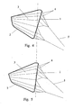
- the figure 1 gives an overall view of the wing. This takes the form of a cone that can be flattened and can have a downward axis and comprising several ranges of wing (3) whose resulting aerodynamic forces are opposite.
- the upper wing propellant range - the larger one - has an upwardly aerodynamic force resultant whose effect is contradicted by two lateral wing propulsive ranges with their resulting rearward-facing aerodynamic forces and a beach lower propulsive - the smaller - with a resultant aerodynamic forces pointing downwards.
- the largest length of the wing (3) is positioned at the highest part and reaches approximately the value of the minor axis of the leading edge (1).
- This flexible and light wing (3) is made of a synthetic fabric that is not very deformable, is not very impregnable with water and is adequately resistant to tearing and wear. It is connected at its base to the leading edge (1) of constant circular section consisting, for example, of an inflatable tube with air chamber. The material must be flexible, light and strong so as not to deform under the pressure of the indoor air and in the face of repeated bending.
- This leading edge can take an oval shape with a rectilinear and horizontal base parallel to the largest axis can rest on the ground or on water stably.
- the other end of the wing (3) constitutes the trailing edge (2) in the form of a recess representing a drop of water at the tip oriented towards the leading edge (1).
- the wing can be traced and cut flat in the form of a half disk whose radius corresponds to the greatest length of the wing; that is approximately the size of the small vertical axis of the leading edge (1).
- the wing in flight is systematically stretched by the wind.
- the bases of these slats (6) are all in contact with the ground when the wing is at rest and part of the upper range of the wing is therefore in the wind and thus facilitates takeoff.
- the other side of the leading edge - facing the wind - is, on the other hand, equipped with an inflatable arch (7) arranged along the minor axis of the leading edge (1) (as indicated in FIG. Fig. 6 and 7 ) or along the long axis so as to avoid laying flat on this side and to force its positioning on the side of the wing (3).
- transverse slats (6) and the arch (7) can be connected to the leading edge (1) so as to require only one inflation port.
- tensioners (8) as shown in Fig. 6 maintain the shape of the leading edge (1) which they connect opposite points while being attached in their center. There are at least two of them.
- tensioners (15) as shown in Fig. 2 connect the rectilinear base of the leading edge (1) to the same point located on the small axis of the leading edge and kept away by a rigid bar (14). This stiffening device maintains the rectilinear shape of the leading edge base (1).
- each line is held by several lines (4) slidably mounted so as to limit the deformation of the profile. from the leading edge (1) and keep the lines (4) tensioned during the variation of the incidence of the wing.
- the other end of the lines is connected to a control system designed to hold the two left lines apart from the two right lines and to vary the length of the high lines relative to that of the low lines.
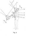
- a bar (9) as indicated in Fig. 8 where the two left-hand lines are wound against each other several turns on a roll (10) of larger diameter than the bar (9), integral with it and of the same axis and placed at the left end and the two lines right arranged in the same way at the right end of the bar (9).
- Two guides (11) are free to rotate around the bar (9) and crossed by the right and left command lines. They ensure the precise winding of the lines (5) on the rollers (10) when the bar is oriented.
- the rotation of the bar (9) in one direction lengthens the high lines and shortens the low lines.
- the passage of the control lines (5) through the guides (11) is made of a sufficiently flexible material to allow movement of the lines when the bar is rotated and strong enough to block the lines the rest of the time. This device maintains the proper winding of the lines (5) around the rollers (10) when the lines are not in tension.
- the length of the control lines (5) can vary greatly from a few meters for a convenient implementation and use to several tens of meters to enjoy a stronger and more regular wind than the surface of the ground or the water.
- the wing Before take-off, the wing rests on the horizontal base of the leading edge (1) and on its transverse slats (6), facing the wind. The leading edge is inclined and part of the upper range of the blade (3) is in the wind. The user then moves by turning the bar (9) until the high and low control lines (5) are slightly stretched. Therefore, the bar is turned to shorten the high lines (and lengthen the low lines - arrow direction from the top of the Fig. 8 ) until the wing rises vertically and reaches its flight position close to that of the Fig. 4 .
- a loosening of the high lines increases the incidence of the upper range of the wing (3).
- the wing then loses a little altitude and reaches a flight position close to that of the Fig. 5 .
- the wing is stationary if the user is stationary and its power is maximum in the direction of the wind.
- An emergency procedure if necessary, consists of releasing the high lines from a flying position far enough to drop the wing which falls rapidly to rest on its stable position on the ground or on the water. balance on the horizontal base of its leading edge (1) and its transverse slats (6).
- the long axis of the leading edge (1) is horizontal when the wing is in the wind axis (representation of the Fig. 2 ).
- the command bar ( Fig. 8 ) is horizontal.
- a pull on the left side of the bar directs the wing away from the wind axis to the left.
- the wing loses a little altitude and its left side is slightly lowered.
- the wing is stationary if the user is stationary and exerts his power on the left side with respect to the direction of the wind.
- a pull on the right side causes the opposite effects.
- This wing with constant propulsion has many possible applications. The most obvious are sports involving a user resting on a board and towed by this wing (kiteboarding, snowkite, mountainboard) and navigation with this wing in substitution or rescue sails or engine.
Landscapes
- Engineering & Computer Science (AREA)
- Aviation & Aerospace Engineering (AREA)
- Wind Motors (AREA)
- Toys (AREA)
- Other Liquid Machine Or Engine Such As Wave Power Use (AREA)
- Bidet-Like Cleaning Device And Other Flush Toilet Accessories (AREA)
- Radiation-Therapy Devices (AREA)
- Percussion Or Vibration Massage (AREA)
Claims (13)
- Antriebsflügel, umfassend ein kegelförmiges Tragwerk mit entgegengesetzten Antriebsbereichen, dessen Basis eine Anströmkante (1) und die abgeschnittene gegenüberliegende Seite eine Abströmkante (2) bildet, sowie Steuerleinen (5), welche das Tragwerk mit einer zu ziehenden oder zu tragenden Last verbinden, dadurch gekennzeichnet, dass die Abströmkante (2) eine elliptische Wassertropfenform mit der Anströmkante (1) zugewandter Spitze aufweist.
- Antriebsflügel nach Anspruch 1, dadurch gekennzeichnet, dass die Anströmkante (1) eine geradlinige Basis aufweist.
- Antriebsflügel nach Anspruch 1 oder 2, dadurch gekennzeichnet, dass das flexible Tragwerk (3) eine abgeflachte Kegelform aufweist, wobei die Anströmkante (1) eine ovale Form mit einer geradlinigen Basis annimmt.
- Antriebsflügel nach einem der vorhergehenden Ansprüche, dadurch gekennzeichnet, dass die Achse des Tragwerks (3) nach unten versetzt ist.
- Antriebsflügel nach einem der vorhergehenden Ansprüche, dadurch gekennzeichnet, dass aufblasbare Querleisten (6) an einem Teil des oberen Bereichs des Tragwerks (3) derart angeordnet sind, dass ihre Basen auf einer gleichen horizontalen Ebene aufliegen, wenn der Flügel am Boden ist.
- Antriebsflügel nach einem der vorhergehenden Ansprüche, dadurch gekennzeichnet, dass Spanner (8) gegenüberliegende Punkte der Anströmkante (1) verbinden und alle in ihrer Mitte befestigt sind.
- Antriebsflügel nach einem der vorhergehenden Ansprüche, dadurch gekennzeichnet, dass Spanner (15) die geradlinige Basis der Anströmkante (1) mit einem gleichen Punkt verbinden, der auf deren Nebenachse gelegen und durch eine starre Stange (5) fern gehalten wird.
- Antriebsflügel nach einem der vorhergehenden Ansprüche, dadurch gekennzeichnet, dass ein Bogen (7) an der von dem Tragwerk abgewandten Seite der Anströmkante (1), entlang einer der beiden Achsen der Anströmkante befestigt ist.
- Antriebsflügel nach einem der vorhergehenden Ansprüche, dadurch gekennzeichnet, dass er eine einzige obere Steuerleine, die mit dem höchsten Punkt der Anströmkante (1) an ihrer vertikalen Nebenachse verbunden ist, sowie zwei untere Steuerleinen umfasst, die an Punkten der Anströmkante (1) angeschlossen sind, welche bezüglich der vertikalen Nebenachse symmetrisch und unterhalb der horizontalen Hauptachse gelegen sind.
- Antriebsflügel nach einem der Ansprüche 1 bis 8, dadurch gekennzeichnet, dass er eine einzige untere Steuerleine, die mit der Mitte der Basis der Anströmkante (1) verbunden ist, sowie zwei obere Steuerleinen umfasst, die an Punkten der Anströmkante (1) angeschlossen sind, welche bezüglich der vertikalen Nebenachse symmetrisch und oberhalb der horizontalen Hauptachse gelegen sind.
- Antriebsflügel nach einem der Ansprüche 1 bis 8, dadurch gekennzeichnet, dass er zwei obere Steuerleinen, die an Punkten der Anströmkante (1) angeschlossen sind, welche bezüglich ihrer vertikalen Nebenachse symmetrisch und oberhalb der horizontalen Hauptachse gelegen sind, sowie zwei untere Steuerleinen umfasst, die an Punkten der Anströmkante (1) angeschlossen sind, welche bezüglich der vertikalen Nebenachse symmetrisch und unterhalb der horizontalen Hauptachse gelegen sind.
- Antriebsflügel nach einem der vorhergehenden Ansprüche, dadurch gekennzeichnet, dass er eine Steuerstange mit zwei um die Stange (9) drehfreien Führungen (11) umfasst, die von den linken und rechten Steuerleinen durchgriffen sind.
- Antriebsflügel nach Anspruch 12, dadurch gekennzeichnet, dass der Durchgang der Steuerleinen (5) durch die Führungen (11) aus einem Material besteht, das flexibel genug ist, um die Bewegung der Leinen zu ermöglichen, wenn die Stange (9) gedreht wird, und widerstandsfähig genug ist, um die Leinen den Rest der Zeit festzulegen.
Applications Claiming Priority (2)
| Application Number | Priority Date | Filing Date | Title |
|---|---|---|---|
| FR0513308A FR2895370A1 (fr) | 2005-12-26 | 2005-12-26 | Aile en forme de cone avec des plages de voilure a effets opposes et une propulsion constante |
| PCT/FR2006/002702 WO2007080257A1 (fr) | 2005-12-26 | 2006-12-12 | Aile en forme de cone avec des plages de voilure a effets opposes et une propulsion constante |
Publications (2)
| Publication Number | Publication Date |
|---|---|
| EP1966038A1 EP1966038A1 (de) | 2008-09-10 |
| EP1966038B1 true EP1966038B1 (de) | 2010-12-08 |
Family
ID=37037034
Family Applications (1)
| Application Number | Title | Priority Date | Filing Date |
|---|---|---|---|
| EP06841907A Not-in-force EP1966038B1 (de) | 2005-12-26 | 2006-12-12 | Kegelförmiger flügel mit tragflächenbereichen mit entgegengesetzten wirkungen und konstantem antrieb |
Country Status (10)
| Country | Link |
|---|---|
| US (1) | US8220752B2 (de) |
| EP (1) | EP1966038B1 (de) |
| CN (1) | CN101374719A (de) |
| AT (1) | ATE490906T1 (de) |
| AU (1) | AU2006334595A1 (de) |
| CA (1) | CA2632988A1 (de) |
| DE (1) | DE602006018787D1 (de) |
| ES (1) | ES2357155T3 (de) |
| FR (1) | FR2895370A1 (de) |
| WO (1) | WO2007080257A1 (de) |
Families Citing this family (9)
| Publication number | Priority date | Publication date | Assignee | Title |
|---|---|---|---|---|
| FR2923799A1 (fr) * | 2007-11-19 | 2009-05-22 | Vincent Leblond | Dispositif de commandes d'une aile de traction. |
| EP2326833B1 (de) * | 2008-08-20 | 2014-07-02 | Skysails GmbH & Co. KG | Aerodynamische windantriebsvorrichtung mit kupplung über bielastische leinen |
| FR2941436B1 (fr) * | 2009-01-26 | 2011-01-28 | Maurice Grenier | Embarcation nautique tractee par au moins une voile aerienne. |
| CN101786498B (zh) * | 2010-03-19 | 2011-12-28 | 清华大学 | 用于船舶航行的可收放的充气型风能伞帆装置 |
| CN101844614B (zh) * | 2010-05-28 | 2012-07-25 | 清华大学 | 用于船舶航行的可收放的远程悬浮型风能伞帆装置 |
| CN107891960A (zh) * | 2017-12-14 | 2018-04-10 | 浙江海洋大学 | 一种筝帆应急保护机构、筝帆及船舶 |
| CN107878721B (zh) * | 2017-12-14 | 2023-05-05 | 浙江海洋大学 | 一种船用筝帆及船舶 |
| RU2690967C1 (ru) * | 2018-02-15 | 2019-06-07 | Дарья Евгеньевна Малерян | Комбинезон для сноукайтинга |
| FR3093007B1 (fr) * | 2019-02-27 | 2021-07-16 | Thierry Marie Morel | Dispositif d'enroulement d'au moins deux lignes, notamment des lignes de kitesurf |
Family Cites Families (16)
| Publication number | Priority date | Publication date | Assignee | Title |
|---|---|---|---|---|
| US1734493A (en) * | 1927-11-09 | 1929-11-05 | Knott Levi | Kite |
| US2483614A (en) * | 1946-08-29 | 1949-10-04 | Frederick J Benson | Toy kite |
| US2941765A (en) * | 1958-11-25 | 1960-06-21 | Marshall H Feldman | Kite construction |
| US3250500A (en) * | 1964-03-23 | 1966-05-10 | Russell S Hall | Kite construction |
| US3547384A (en) * | 1969-04-28 | 1970-12-15 | Louis J Clark | Air foil flying device with multiple-stage lift areas |
| US3740008A (en) * | 1971-10-12 | 1973-06-19 | E Grauel | Multi-keeled kite |
| USD273211S (en) * | 1981-04-24 | 1984-03-27 | Zether Limited | Kite |
| FI820813L (fi) * | 1982-03-10 | 1983-09-11 | Maorten Bondestam | Drake |
| FR2581961A1 (fr) * | 1984-11-16 | 1986-11-21 | Dominique Legaignoux | Aile propulsive |
| US5234182A (en) * | 1991-05-17 | 1993-08-10 | Renecle Keith V | Kite |
| US5669803A (en) * | 1995-09-22 | 1997-09-23 | Sweed; James | Kick glider toy |
| US6062510A (en) * | 1999-09-27 | 2000-05-16 | De La Melena; Carlos | Kite |
| US6260803B1 (en) * | 2000-03-15 | 2001-07-17 | Rick E. Hunts | Kite tether control with attachment to the body |
| US7140576B2 (en) * | 2003-02-07 | 2006-11-28 | Tony Logosz | Inflatable wing with manifold |
| US7093803B2 (en) * | 2003-12-16 | 2006-08-22 | Culp David A | Apparatus and method for aerodynamic wing |
| US6955325B1 (en) * | 2004-03-31 | 2005-10-18 | Don Tabor | Delta kite with flight stabilizing, air-passing ring structure |
-
2005
- 2005-12-26 FR FR0513308A patent/FR2895370A1/fr not_active Withdrawn
-
2006
- 2006-12-12 CN CNA2006800471836A patent/CN101374719A/zh active Pending
- 2006-12-12 AT AT06841907T patent/ATE490906T1/de not_active IP Right Cessation
- 2006-12-12 EP EP06841907A patent/EP1966038B1/de not_active Not-in-force
- 2006-12-12 AU AU2006334595A patent/AU2006334595A1/en not_active Abandoned
- 2006-12-12 US US12/159,092 patent/US8220752B2/en not_active Expired - Fee Related
- 2006-12-12 CA CA002632988A patent/CA2632988A1/fr not_active Abandoned
- 2006-12-12 DE DE602006018787T patent/DE602006018787D1/de active Active
- 2006-12-12 WO PCT/FR2006/002702 patent/WO2007080257A1/fr active Application Filing
- 2006-12-12 ES ES06841907T patent/ES2357155T3/es active Active
Also Published As
| Publication number | Publication date |
|---|---|
| CA2632988A1 (fr) | 2007-07-19 |
| CN101374719A (zh) | 2009-02-25 |
| AU2006334595A1 (en) | 2007-07-19 |
| ES2357155T3 (es) | 2011-04-19 |
| DE602006018787D1 (de) | 2011-01-20 |
| ATE490906T1 (de) | 2010-12-15 |
| FR2895370A1 (fr) | 2007-06-29 |
| EP1966038A1 (de) | 2008-09-10 |
| US20090134278A1 (en) | 2009-05-28 |
| US8220752B2 (en) | 2012-07-17 |
| WO2007080257A1 (fr) | 2007-07-19 |
Similar Documents
| Publication | Publication Date | Title |
|---|---|---|
| EP1966038B1 (de) | Kegelförmiger flügel mit tragflächenbereichen mit entgegengesetzten wirkungen und konstantem antrieb | |
| WO1986002902A1 (fr) | Aile propulsive a armature gonflable | |
| FR2538772A1 (fr) | Navire a voile a hydropteres | |
| WO2022218921A1 (fr) | Aile de traction autonome | |
| FR2462337A1 (fr) | Engin a voile a contre-gite automatique | |
| WO1993011999A1 (fr) | Dispositif de loisir sportif aerien | |
| FR2822798A1 (fr) | Greement de voilure pour une embarcation mue par le vent | |
| EP3778376B1 (de) | Autonomer kite-antrieb | |
| WO1990005663A1 (fr) | Structure de cerf-volant du type aile a caissons gonflables | |
| FR2978106A1 (fr) | Voilure amovible | |
| WO2016062725A1 (fr) | Greement simplifiant les manoeuvres de changement d'amure | |
| FR2639605A1 (fr) | Aile volante souple munie de cables tracteurs destinee notamment a tirer un bateau | |
| FR2542274A2 (fr) | Voilier a derive plongeante decalee au vent d'une voile sustentatrice | |
| FR2913951A1 (fr) | Aile a caissons avec diminution du ballonnement | |
| FR2526749A1 (fr) | Voilier a aile a profil hydrodynamique | |
| EP0445217A1 (de) | Profilsegeleinrichtung | |
| EP1802522B1 (de) | Vorrichtung zum anflanschen von aufblasbarem flügel mit lastumschaltung | |
| EP4347384A1 (de) | Segelantriebselement, segelangetriebenes fahrzeug | |
| WO2022248813A1 (fr) | Element de propulsion velique, vehicule a propulsion velique | |
| FR3121424A1 (fr) | Dispositif aerien pour optimiser les engins a voiles | |
| WO2001079059A1 (fr) | Dispositif de propulsion d'un engin nautique | |
| FR3033765A1 (fr) | Voile aile a orientation automatique | |
| FR2639317A1 (fr) | Structure de voile a caissons gonflables | |
| FR2856651A1 (fr) | Vehicule aquatique a propulsion eolienne pour planer au dessus de l'eau sans que le corps du vehicule soit en contact avec l'eau-l'appui dans l'eau se fait a l'aide d'une derive autonome | |
| BE905303A (fr) | Un propulseur a voile. |
Legal Events
| Date | Code | Title | Description |
|---|---|---|---|
| PUAI | Public reference made under article 153(3) epc to a published international application that has entered the european phase |
Free format text: ORIGINAL CODE: 0009012 |
|
| 17P | Request for examination filed |
Effective date: 20080623 |
|
| AK | Designated contracting states |
Kind code of ref document: A1 Designated state(s): AT BE BG CH CY CZ DE DK EE ES FI FR GB GR HU IE IS IT LI LT LU LV MC NL PL PT RO SE SI SK TR |
|
| 17Q | First examination report despatched |
Effective date: 20081117 |
|
| GRAP | Despatch of communication of intention to grant a patent |
Free format text: ORIGINAL CODE: EPIDOSNIGR1 |
|
| GRAS | Grant fee paid |
Free format text: ORIGINAL CODE: EPIDOSNIGR3 |
|
| GRAA | (expected) grant |
Free format text: ORIGINAL CODE: 0009210 |
|
| AK | Designated contracting states |
Kind code of ref document: B1 Designated state(s): AT BE BG CH CY CZ DE DK EE ES FI FR GB GR HU IE IS IT LI LT LU LV MC NL PL PT RO SE SI SK TR |
|
| REG | Reference to a national code |
Ref country code: GB Ref legal event code: FG4D Free format text: NOT ENGLISH |
|
| REG | Reference to a national code |
Ref country code: CH Ref legal event code: EP |
|
| REG | Reference to a national code |
Ref country code: IE Ref legal event code: FG4D |
|
| REF | Corresponds to: |
Ref document number: 602006018787 Country of ref document: DE Date of ref document: 20110120 Kind code of ref document: P |
|
| REG | Reference to a national code |
Ref country code: NL Ref legal event code: VDEP Effective date: 20101208 |
|
| REG | Reference to a national code |
Ref country code: ES Ref legal event code: FG2A Ref document number: 2357155 Country of ref document: ES Kind code of ref document: T3 Effective date: 20110419 |
|
| PG25 | Lapsed in a contracting state [announced via postgrant information from national office to epo] |
Ref country code: LT Free format text: LAPSE BECAUSE OF FAILURE TO SUBMIT A TRANSLATION OF THE DESCRIPTION OR TO PAY THE FEE WITHIN THE PRESCRIBED TIME-LIMIT Effective date: 20101208 |
|
| LTIE | Lt: invalidation of european patent or patent extension |
Effective date: 20101208 |
|
| PG25 | Lapsed in a contracting state [announced via postgrant information from national office to epo] |
Ref country code: AT Free format text: LAPSE BECAUSE OF FAILURE TO SUBMIT A TRANSLATION OF THE DESCRIPTION OR TO PAY THE FEE WITHIN THE PRESCRIBED TIME-LIMIT Effective date: 20101208 Ref country code: NL Free format text: LAPSE BECAUSE OF FAILURE TO SUBMIT A TRANSLATION OF THE DESCRIPTION OR TO PAY THE FEE WITHIN THE PRESCRIBED TIME-LIMIT Effective date: 20101208 Ref country code: FI Free format text: LAPSE BECAUSE OF FAILURE TO SUBMIT A TRANSLATION OF THE DESCRIPTION OR TO PAY THE FEE WITHIN THE PRESCRIBED TIME-LIMIT Effective date: 20101208 Ref country code: SI Free format text: LAPSE BECAUSE OF FAILURE TO SUBMIT A TRANSLATION OF THE DESCRIPTION OR TO PAY THE FEE WITHIN THE PRESCRIBED TIME-LIMIT Effective date: 20101208 Ref country code: LV Free format text: LAPSE BECAUSE OF FAILURE TO SUBMIT A TRANSLATION OF THE DESCRIPTION OR TO PAY THE FEE WITHIN THE PRESCRIBED TIME-LIMIT Effective date: 20101208 Ref country code: BG Free format text: LAPSE BECAUSE OF FAILURE TO SUBMIT A TRANSLATION OF THE DESCRIPTION OR TO PAY THE FEE WITHIN THE PRESCRIBED TIME-LIMIT Effective date: 20110308 Ref country code: CY Free format text: LAPSE BECAUSE OF FAILURE TO SUBMIT A TRANSLATION OF THE DESCRIPTION OR TO PAY THE FEE WITHIN THE PRESCRIBED TIME-LIMIT Effective date: 20101208 Ref country code: SE Free format text: LAPSE BECAUSE OF FAILURE TO SUBMIT A TRANSLATION OF THE DESCRIPTION OR TO PAY THE FEE WITHIN THE PRESCRIBED TIME-LIMIT Effective date: 20101208 |
|
| PGFP | Annual fee paid to national office [announced via postgrant information from national office to epo] |
Ref country code: IT Payment date: 20110315 Year of fee payment: 5 |
|
| BERE | Be: lapsed |
Owner name: LEBLOND, VINCENT Effective date: 20101231 |
|
| REG | Reference to a national code |
Ref country code: IE Ref legal event code: FD4D |
|
| PG25 | Lapsed in a contracting state [announced via postgrant information from national office to epo] |
Ref country code: EE Free format text: LAPSE BECAUSE OF FAILURE TO SUBMIT A TRANSLATION OF THE DESCRIPTION OR TO PAY THE FEE WITHIN THE PRESCRIBED TIME-LIMIT Effective date: 20101208 Ref country code: CZ Free format text: LAPSE BECAUSE OF FAILURE TO SUBMIT A TRANSLATION OF THE DESCRIPTION OR TO PAY THE FEE WITHIN THE PRESCRIBED TIME-LIMIT Effective date: 20101208 Ref country code: PT Free format text: LAPSE BECAUSE OF FAILURE TO SUBMIT A TRANSLATION OF THE DESCRIPTION OR TO PAY THE FEE WITHIN THE PRESCRIBED TIME-LIMIT Effective date: 20110408 Ref country code: IE Free format text: LAPSE BECAUSE OF FAILURE TO SUBMIT A TRANSLATION OF THE DESCRIPTION OR TO PAY THE FEE WITHIN THE PRESCRIBED TIME-LIMIT Effective date: 20101208 Ref country code: GR Free format text: LAPSE BECAUSE OF FAILURE TO SUBMIT A TRANSLATION OF THE DESCRIPTION OR TO PAY THE FEE WITHIN THE PRESCRIBED TIME-LIMIT Effective date: 20110309 Ref country code: IS Free format text: LAPSE BECAUSE OF FAILURE TO SUBMIT A TRANSLATION OF THE DESCRIPTION OR TO PAY THE FEE WITHIN THE PRESCRIBED TIME-LIMIT Effective date: 20110408 Ref country code: MC Free format text: LAPSE BECAUSE OF NON-PAYMENT OF DUE FEES Effective date: 20101231 |
|
| REG | Reference to a national code |
Ref country code: CH Ref legal event code: PL |
|
| PG25 | Lapsed in a contracting state [announced via postgrant information from national office to epo] |
Ref country code: RO Free format text: LAPSE BECAUSE OF FAILURE TO SUBMIT A TRANSLATION OF THE DESCRIPTION OR TO PAY THE FEE WITHIN THE PRESCRIBED TIME-LIMIT Effective date: 20101208 Ref country code: SK Free format text: LAPSE BECAUSE OF FAILURE TO SUBMIT A TRANSLATION OF THE DESCRIPTION OR TO PAY THE FEE WITHIN THE PRESCRIBED TIME-LIMIT Effective date: 20101208 Ref country code: PL Free format text: LAPSE BECAUSE OF FAILURE TO SUBMIT A TRANSLATION OF THE DESCRIPTION OR TO PAY THE FEE WITHIN THE PRESCRIBED TIME-LIMIT Effective date: 20101208 |
|
| PG25 | Lapsed in a contracting state [announced via postgrant information from national office to epo] |
Ref country code: BE Free format text: LAPSE BECAUSE OF NON-PAYMENT OF DUE FEES Effective date: 20101231 |
|
| PLBE | No opposition filed within time limit |
Free format text: ORIGINAL CODE: 0009261 |
|
| STAA | Information on the status of an ep patent application or granted ep patent |
Free format text: STATUS: NO OPPOSITION FILED WITHIN TIME LIMIT |
|
| PG25 | Lapsed in a contracting state [announced via postgrant information from national office to epo] |
Ref country code: LI Free format text: LAPSE BECAUSE OF NON-PAYMENT OF DUE FEES Effective date: 20101231 Ref country code: DK Free format text: LAPSE BECAUSE OF FAILURE TO SUBMIT A TRANSLATION OF THE DESCRIPTION OR TO PAY THE FEE WITHIN THE PRESCRIBED TIME-LIMIT Effective date: 20101208 Ref country code: CH Free format text: LAPSE BECAUSE OF NON-PAYMENT OF DUE FEES Effective date: 20101231 |
|
| 26N | No opposition filed |
Effective date: 20110909 |
|
| REG | Reference to a national code |
Ref country code: DE Ref legal event code: R119 Ref document number: 602006018787 Country of ref document: DE Effective date: 20110701 |
|
| PG25 | Lapsed in a contracting state [announced via postgrant information from national office to epo] |
Ref country code: DE Free format text: LAPSE BECAUSE OF NON-PAYMENT OF DUE FEES Effective date: 20110701 |
|
| PGFP | Annual fee paid to national office [announced via postgrant information from national office to epo] |
Ref country code: ES Payment date: 20111220 Year of fee payment: 6 |
|
| PG25 | Lapsed in a contracting state [announced via postgrant information from national office to epo] |
Ref country code: LU Free format text: LAPSE BECAUSE OF NON-PAYMENT OF DUE FEES Effective date: 20101212 Ref country code: HU Free format text: LAPSE BECAUSE OF FAILURE TO SUBMIT A TRANSLATION OF THE DESCRIPTION OR TO PAY THE FEE WITHIN THE PRESCRIBED TIME-LIMIT Effective date: 20110609 |
|
| PG25 | Lapsed in a contracting state [announced via postgrant information from national office to epo] |
Ref country code: TR Free format text: LAPSE BECAUSE OF FAILURE TO SUBMIT A TRANSLATION OF THE DESCRIPTION OR TO PAY THE FEE WITHIN THE PRESCRIBED TIME-LIMIT Effective date: 20101208 |
|
| PGFP | Annual fee paid to national office [announced via postgrant information from national office to epo] |
Ref country code: GB Payment date: 20130613 Year of fee payment: 7 |
|
| PG25 | Lapsed in a contracting state [announced via postgrant information from national office to epo] |
Ref country code: IT Free format text: LAPSE BECAUSE OF NON-PAYMENT OF DUE FEES Effective date: 20121212 |
|
| REG | Reference to a national code |
Ref country code: ES Ref legal event code: FD2A Effective date: 20140602 |
|
| PG25 | Lapsed in a contracting state [announced via postgrant information from national office to epo] |
Ref country code: ES Free format text: LAPSE BECAUSE OF NON-PAYMENT OF DUE FEES Effective date: 20121213 |
|
| GBPC | Gb: european patent ceased through non-payment of renewal fee |
Effective date: 20131212 |
|
| PG25 | Lapsed in a contracting state [announced via postgrant information from national office to epo] |
Ref country code: GB Free format text: LAPSE BECAUSE OF NON-PAYMENT OF DUE FEES Effective date: 20131212 |
|
| REG | Reference to a national code |
Ref country code: FR Ref legal event code: PLFP Year of fee payment: 10 |
|
| REG | Reference to a national code |
Ref country code: FR Ref legal event code: PLFP Year of fee payment: 11 |
|
| REG | Reference to a national code |
Ref country code: FR Ref legal event code: PLFP Year of fee payment: 12 |
|
| PGFP | Annual fee paid to national office [announced via postgrant information from national office to epo] |
Ref country code: FR Payment date: 20201228 Year of fee payment: 15 |
|
| PG25 | Lapsed in a contracting state [announced via postgrant information from national office to epo] |
Ref country code: FR Free format text: LAPSE BECAUSE OF NON-PAYMENT OF DUE FEES Effective date: 20211231 |