EP1965241A1 - Zoom lens of the teleobjective type having five lens groups and an image stabilisation function - Google Patents
Zoom lens of the teleobjective type having five lens groups and an image stabilisation function Download PDFInfo
- Publication number
- EP1965241A1 EP1965241A1 EP08152175A EP08152175A EP1965241A1 EP 1965241 A1 EP1965241 A1 EP 1965241A1 EP 08152175 A EP08152175 A EP 08152175A EP 08152175 A EP08152175 A EP 08152175A EP 1965241 A1 EP1965241 A1 EP 1965241A1
- Authority
- EP
- European Patent Office
- Prior art keywords
- lens unit
- lens
- refractive power
- zoom
- zoom lens
- Prior art date
- Legal status (The legal status is an assumption and is not a legal conclusion. Google has not performed a legal analysis and makes no representation as to the accuracy of the status listed.)
- Granted
Links
- 230000006641 stabilisation Effects 0.000 title description 29
- 230000003287 optical effect Effects 0.000 claims abstract description 35
- 238000003384 imaging method Methods 0.000 claims abstract description 9
- 230000004075 alteration Effects 0.000 description 41
- 238000011105 stabilization Methods 0.000 description 28
- 230000000087 stabilizing effect Effects 0.000 description 24
- 230000011514 reflex Effects 0.000 description 4
- 238000010586 diagram Methods 0.000 description 3
- 230000035945 sensitivity Effects 0.000 description 3
- 238000006243 chemical reaction Methods 0.000 description 2
- 206010010071 Coma Diseases 0.000 description 1
- 230000015556 catabolic process Effects 0.000 description 1
- 230000000295 complement effect Effects 0.000 description 1
- 238000006731 degradation reaction Methods 0.000 description 1
- 238000006073 displacement reaction Methods 0.000 description 1
- 230000000694 effects Effects 0.000 description 1
- 229910044991 metal oxide Inorganic materials 0.000 description 1
- 150000004706 metal oxides Chemical class 0.000 description 1
- 238000012986 modification Methods 0.000 description 1
- 230000004048 modification Effects 0.000 description 1
- 210000001747 pupil Anatomy 0.000 description 1
- 239000004065 semiconductor Substances 0.000 description 1
Images










Classifications
-
- G—PHYSICS
- G02—OPTICS
- G02B—OPTICAL ELEMENTS, SYSTEMS OR APPARATUS
- G02B27/00—Optical systems or apparatus not provided for by any of the groups G02B1/00 - G02B26/00, G02B30/00
- G02B27/64—Imaging systems using optical elements for stabilisation of the lateral and angular position of the image
- G02B27/646—Imaging systems using optical elements for stabilisation of the lateral and angular position of the image compensating for small deviations, e.g. due to vibration or shake
-
- G—PHYSICS
- G02—OPTICS
- G02B—OPTICAL ELEMENTS, SYSTEMS OR APPARATUS
- G02B15/00—Optical objectives with means for varying the magnification
- G02B15/14—Optical objectives with means for varying the magnification by axial movement of one or more lenses or groups of lenses relative to the image plane for continuously varying the equivalent focal length of the objective
- G02B15/143—Optical objectives with means for varying the magnification by axial movement of one or more lenses or groups of lenses relative to the image plane for continuously varying the equivalent focal length of the objective having three groups only
- G02B15/1431—Optical objectives with means for varying the magnification by axial movement of one or more lenses or groups of lenses relative to the image plane for continuously varying the equivalent focal length of the objective having three groups only the first group being positive
- G02B15/143105—Optical objectives with means for varying the magnification by axial movement of one or more lenses or groups of lenses relative to the image plane for continuously varying the equivalent focal length of the objective having three groups only the first group being positive arranged +-+
Definitions
- the present invention relates to a zoom lens having an image stabilizing function for use in an image pickup apparatus, such as a single-lens reflex camera, a digital camera, a video camcorder, or a film camera.
- an image pickup apparatus such as a single-lens reflex camera, a digital camera, a video camcorder, or a film camera.
- a zoom lens is desired to be compact, have a high zoom ratio, and provide high imaging performance throughout the entire zoom range.
- a zoom lens with a wide zoom range and a high zoom ratio there is known a telephoto zoom lens having a long focal length at the telephoto end.
- the telephoto zoom lens tends to be large in overall size and weight.
- the imaging position is displaced (or the photographed image is blurred) by an amount according to the angle of the inclination and a focal length corresponding to the zooming position at the time when the zoom lens was inclined.
- hand-induced shake or vibration in the zoom lens
- hand-induced shake or vibration in the zoom lens
- Telephoto zoom lens having an image stabilizing function is known.
- at least one of the lens units is moved in a direction substantially perpendicular to the optical axis so as to compensate (or correct) for image blur caused by vibration.
- zoom lenses of this type is a four-unit zoom lens which includes four lens units having positive, negative, positive, and positive refractive power in order from the object side to the image side, and in which a lens subunit constituting part of the third lens unit is moved in a direction perpendicular to the optical axis to compensate for image blur (see, for example, US Patent No. 7,253,965 and US Patent No. 6,046,852 ).
- a five-unit zoom lens which includes five lens units having positive, negative, positive, negative, and positive refractive power in order from the object side to the image side, and in which the fourth lens unit is moved in a direction perpendicular to the optical axis to compensate for image blur (see, for example, US Patent No. 6,025,962 ).
- eccentric aberration that occurs in the image stabilizing lens unit is formed on the image plane at the imaging magnification of a lens unit arranged on the image side of the image stabilizing lens unit.
- the present invention provides a zoom lens including a mechanism for compensation of vibration (or for image stabilization) and having an image stabilizing function that makes it possible to realize a high-quality image through the compensation of vibration.
- the present invention in its first aspect provides a zoom lens as specified in Claims 1 through 9.
- the present invention in its second aspect provides an image pickup apparatus as specified in Claim 10.
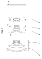
- Fig. 1 is a cross-sectional view of a zoom lens according to embodiment 1 of the present invention and illustrates a state in which an object at infinity is in focus at the wide-angle end of the zooming range (short focal length end).
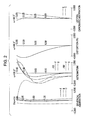
- Fig. 2 shows longitudinal aberrations that occur when an object at infinity is in focus at the wide-angle end of the zoom lens of embodiment 1.
- Fig. 3 shows longitudinal aberrations that occur when an object at infinity is in focus at the telephoto end (long focal length end) of the zoom lens of embodiment 1.
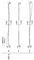
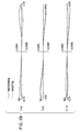
- Fig. 4 shows lateral aberrations that occur when an object at infinity is in focus at the wide-angle end of the zoom lens of embodiment 1 and image stabilization is performed with the zoom lens inclined at 0.3°.
- Fig. 5 shows lateral aberrations that occur when an object at infinity is in focus at the telephoto end of the zoom lens of embodiment 1 and image stabilization is performed with the zoom lens inclined at 0.3°.
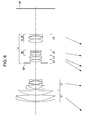
- Fig. 6 is a cross-sectional view of a zoom lens according to embodiment 2 of the present invention and illustrates a state in which an object at infinity is in focus at the wide-angle end.
- Fig. 7 shows longitudinal aberrations that occur when an object at infinity is in focus at the wide-angle end of the zoom lens of embodiment 2.
- Fig. 8 shows longitudinal aberrations that occur when an object at infinity is in focus at the telephoto end of the zoom lens of embodiment 2.
- Fig. 9 shows lateral aberrations that occur when an object at infinity is in focus at the wide-angle end of the zoom lens of embodiment 2 and image stabilization is performed with the zoom lens inclined at 0.3°.
- Fig. 10 shows lateral aberrations that occur when an object at infinity is in focus at the telephoto end of the zoom lens of embodiment 2 and image stabilization is performed with the zoom lens inclined at 0.3°.
- Fig. 11 is a cross-sectional view of a zoom lens according to embodiment 3 of the present invention and illustrates a state in which an object at infinity is in focus at the wide-angle end.
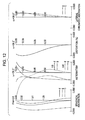
- Fig. 12 shows longitudinal aberrations that occur when an object at infinity is in focus at the wide-angle end of the zoom lens of embodiment 3.
- Fig. 13 shows longitudinal aberrations that occur when an object at infinity is in focus at the telephoto end of the zoom lens of embodiment 3.
- Fig. 14 shows lateral aberrations that occur when an object at infinity is in focus at the wide-angle end of the zoom lens of embodiment 3 and image stabilization is performed with the zoom lens inclined at 0.3°.
- Fig. 15 shows lateral aberrations that occur when an object at infinity is in focus at the telephoto end of the zoom lens of embodiment 3 and image stabilization is performed with the zoom lens inclined at 0.3°.
- Fig. 16 is a cross-sectional view of a zoom lens according to embodiment 4 of the present invention and illustrates a state in which an object at infinity is in focus at the wide-angle end.
- Fig. 17 shows longitudinal aberrations that occur when an object at infinity is in focus at the wide-angle end of the zoom lens of embodiment 4.
- Fig. 18 shows longitudinal aberrations that occur when an object at infinity is in focus at the telephoto end of the zoom lens of embodiment 4.
- Fig. 19 shows lateral aberrations that occur when an object at infinity is in focus at the wide-angle end of the zoom lens of embodiment 4 and image stabilization is performed with the zoom lens inclined at 0.3°.
- Fig. 20 shows lateral aberrations that occur when an object at infinity is in focus at the telephoto end of the zoom lens of embodiment 4 and image stabilization is performed with the zoom lens inclined at 0.3°.
- Fig. 21 is a cross-sectional view of a zoom lens according to embodiment 5 of the present invention and illustrates a state in which an object at infinity is in focus at the wide-angle end.
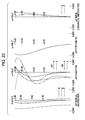
- Fig. 22 shows longitudinal aberrations that occur when an object at infinity is in focus at the wide-angle end of the zoom lens of embodiment 5.
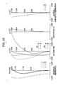
- Fig. 23 shows longitudinal aberrations that occur when an object at infinity is in focus at the telephoto end of the zoom lens of embodiment 5.
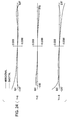
- Fig. 24 shows lateral aberrations that occur when an object at infinity is in focus at the wide-angle end of the zoom lens of embodiment 5 and image stabilization is performed with the zoom lens inclined at 0.3°.
- Fig. 25 shows lateral aberrations that occur when an object at infinity is in focus at the telephoto end of the zoom lens of embodiment 5 and image stabilization is performed with the zoom lens inclined at 0.3°.
- Fig. 26 is a cross-sectional view of a zoom lens according to embodiment 6 of the present invention and illustrates a state in which an object at infinity is in focus at the wide-angle end.
- Fig. 27 shows longitudinal aberrations that occur when an object at infinity is in focus at the wide-angle end of the zoom lens of embodiment 6.
- Fig. 28 shows longitudinal aberrations that occur when an object at infinity is in focus at the telephoto end of the zoom lens of embodiment 6.
- Fig. 29 shows lateral aberrations that occur when an object at infinity is in focus at the wide-angle end of the zoom lens of embodiment 6 and image stabilization is performed with the zoom lens inclined at 0.3°.
- Fig. 30 shows lateral aberrations that occur when an object at infinity is in focus at the telephoto end of the zoom lens of embodiment 6 and image stabilization is performed with the zoom lens inclined at 0.3°.
- Fig. 31 is a schematic diagram of a camera (image pickup apparatus) including a zoom lens according to at least one embodiment of the present invention.
- a zoom lens of the present invention includes, in order from the object side to the image side, a first lens unit (L1) having positive refractive power, a second lens unit (L2) having negative refractive power, and a rear lens group (Lr) including at least one lens unit having positive refractive power.
- the rear lens group includes a lens unit (image stabilizing lens unit) IS having negative refractive power and a lens unit R_IS having positive refractive power.
- the lens unit IS is movable in a direction having a component perpendicular to the optical axis so as to displace the imaging position.
- the lens unit R_IS is arranged on the image side of the lens unit IS and is movable for zooming. During zooming, the distance between the lens unit IS and the lens unit R_IS is varied.
- the zoom lens of each embodiment is a photographing lens system included in an image pickup apparatus, such as a video camcorder, a digital camera, or a silver-halide film camera.
- the zoom lens may be releasably secured to the camera body.
- the object (front) side is on the left and the image (rear) side is on the right.
- Li denotes the i-th lens unit from the object side; and Lr denotes a rear lens group including a plurality of lens units.
- the cross-sectional views of Fig. 1 , Fig. 11 , Fig. 16 , and Fig. 21 each illustrate a first lens unit L1 having positive refractive power, a second lens unit L2 having negative refractive power, and a rear lens group Lr.
- the rear lens group Lr includes a third lens unit L3 having positive refractive power, a fourth lens unit L4 having negative refractive power, and a fifth lens unit L5 having positive refractive power.
- the fourth lens unit L4 is a lens unit in which a lens unit (image stabilizing lens unit) having negative refractive power and constituting all or part of the fourth lens unit L4 is movable in a direction having a component perpendicular to the optical axis, so as to displace the imaging position.
- a lens unit image stabilizing lens unit
- optical power refers to optical power and is the reciprocal of the focal length.
- the cross-sectional view of Fig. 6 illustrates a first lens unit L1 having positive refractive power, a second lens unit L2 having negative refractive power, and a rear lens group Lr.
- the rear lens group Lr includes a third lens unit L3 having positive refractive power, a fourth lens unit L4 having positive refractive power, a fifth lens unit L5 having negative refractive power, and a sixth lens unit L6 having positive refractive power.
- the fifth lens unit L5 is a lens unit (image stabilizing lens unit) movable in a direction having a component perpendicular to the optical axis, so as to displace the imaging position.
- the cross-sectional view of Fig. 26 illustrates a first lens unit L1 having positive refractive power, a second lens unit L2 having negative refractive power, and a rear lens group Lr.
- the rear lens group Lr includes a third lens unit L3 having positive refractive power and a fourth lens unit L4 having positive refractive power.
- the third lens unit L3 is a lens unit in which a part of the third lens unit having negative refractive power is movable in a direction having a component perpendicular to the optical axis, so as to displace the imaging position.
- Each cross-sectional view of the zoom lens also illustrates an aperture stop SP and an image plane IP.
- the aperture stop SP is either arranged on the object side of the rear lens group Lr, or arranged in the rear lens group Lr. In the embodiments described below, the aperture stop SP is located on the object side of the third lens unit L3.
- a photosensitive surface is located at the position of the image plane IP.
- the zoom lens is used as a photographing optical system for a video camcorder or a digital still camera
- the photosensitive surface corresponds to an image pickup surface of a solid-state image pickup element (photoelectric conversion element), such as a charge-coupled device (CCD) sensor or a complementary metal oxide semiconductor (CMOS) sensor.
- the zoom lens is used as a photographing optical system for a silver-halide film camera, the photosensitive surface corresponds to a film surface in the camera.
- d, g, and C denote a d-line, a g-line, and a C-line, respectively;
- ⁇ M and ⁇ S denote a meridional image plane and a sagittal image plane, respectively;
- ⁇ denotes a half angle of view;
- Fno denotes an F-number.
- a lateral chromatic aberration is indicated by the g-line and C-line.
- Y denotes the height of an image
- a solid line and a dashed line indicate a meridional image plane and a sagittal image, respectively
- the horizontal axis represents the height on the pupil plane.
- the terms "wide-angle end” and “telephoto end” refer to zooming positions at the time when lens units (magnification-varying lens units) are located at either end of a mechanically movable range along the optical axis.
- the locus of movement of each lens unit during zooming from the wide-angle end to the telephoto end is indicated by an arrow in the cross-sectional view Figures.
- the zoom lens includes, in order from the object side to the image side, the first lens unit L1 having positive refractive power, the second lens unit L2 having negative refractive power, the third lens unit L3 having positive refractive power, the fourth lens unit L4 having negative refractive power, and the fifth lens unit L5 having positive refractive power.
- the zoom lens includes, in order from the object side to the image side, the first lens unit L1 having positive refractive power, the second lens unit L2 having negative refractive power, the third lens unit L3 having positive refractive power, the fourth lens unit L4 having negative refractive power, and the fifth lens unit L5 having positive refractive power.
- distances between the lens units are varied.
- the first lens unit L1 is moved to the object side; the second lens unit L2 is moved to increase the distance between the second lens unit L2 and the first lens unit L1; the third lens unit L3 is moved to the object side to reduce the distance between the third lens unit L3 and the second lens unit L2; the fourth lens unit L4 is moved to the object side to increase the distance between the fourth lens unit L4 and the third lens unit L3; and the fifth lens unit L5 is moved to the object side to reduce the distance between the fifth lens unit L5 and the fourth lens unit L4.
- the aperture stop SP is moved together with the third lens unit L3.
- the aperture stop SP may be moved independent of the lens units during zooming.
- the zoom lens includes, in order from the object side to the image side, the first lens unit L1 having positive refractive power, the second lens unit L2 having negative refractive power, the third lens unit L3 having positive refractive power, the fourth lens unit L4 having positive refractive power, the fifth lens unit L5 having negative refractive power, and the sixth lens unit L6 having positive refractive power.
- the zoom lens includes, in order from the object side to the image side, the first lens unit L1 having positive refractive power, the second lens unit L2 having negative refractive power, the third lens unit L3 having positive refractive power, the fourth lens unit L4 having positive refractive power, the fifth lens unit L5 having negative refractive power, and the sixth lens unit L6 having positive refractive power.
- the first lens unit L1 is moved to the object side; the second lens unit L2 is moved to increase the distance between the second lens unit L2 and the first lens unit L1; the third lens unit L3 is moved to the object side to reduce the distance between the third lens unit L3 and the second lens unit L2; the fourth lens unit L4 is moved to the object side to increase the distance between the fourth lens unit L4 and the third lens unit L3; the fifth lens unit L5 is moved to the object side to increase the distance between the fifth lens unit L5 and the fourth lens unit L4; and the sixth lens unit L6 is moved to the object side to reduce the distance between the sixth lens unit L6 and the fifth lens unit L5.
- the aperture stop SP is moved together with the third lens unit L3.
- the aperture stop SP may be moved independent of the lens units during zooming.
- the zoom lens includes, in order from the object side to the image side, the first lens unit L1 having positive refractive power, the second lens unit L2 having negative refractive power, the third lens unit L3 having positive refractive power, and the fourth lens unit L4 having positive refractive power.
- the zoom lens includes, in order from the object side to the image side, the first lens unit L1 having positive refractive power, the second lens unit L2 having negative refractive power, the third lens unit L3 having positive refractive power, and the fourth lens unit L4 having positive refractive power.
- the first lens unit L1 is moved to the object side; the second lens unit L2 is moved to increase the distance between the second lens unit L2 and the first lens unit L1; the third lens unit L3 is moved to the object side to reduce the distance between the third lens unit L3 and the second lens unit L2; and the fourth lens unit L4 is moved to the object side to reduce the distance between the fourth lens unit L4 and the third lens unit L3.
- the aperture stop SP is moved together with the third lens unit L3.
- the aperture stop SP may be moved independent of the lens units during zooming.
- focusing is performed by moving the second lens unit L2 along the optical axis.
- focusing may be performed by moving the entire zoom lens or any one of the lens units.
- the lens unit IS in the rear lens group Lr is movable in a direction having a component substantially perpendicular to the optical axis so as to displace an image in a direction substantially perpendicular to the optical axis.
- image blur caused by vibration of the entire zoom lens can be corrected.
- the lens unit IS corresponds to the fourth lens unit L4.
- the lens unit IS corresponds to the fifth lens unit L5.
- the lens unit IS corresponds to a lens unit having negative refractive power and constituting part of the fourth lens unit L4.
- the lens unit IS corresponds to a lens unit having negative refractive power and constituting part of the third lens unit L3.
- the lens unit R_IS that is movable during zooming and is located on the image side of the lens unit IS for image stabilization corresponds to the fifth lens unit L5.
- the lens unit R_IS corresponds to the sixth lens unit L6.
- the lens unit R_IS corresponds to the fourth lens unit L4.
- an additional lens unit having small refractive power may be provided on the object side of the first lens unit L1 or on the image side of the lens unit closest to the image side.
- a teleconverter lens or a wide converter lens may be provided on the object side or image side.
- fIS is the focal length of the lens unit IS
- fT is the focal length of the entire zoom lens at the telephoto end
- f1 is the focal length of the first lens unit L1
- fR_IS is the focal length of the lens unit R_IS.
- Condition (1) defines the focal length of the lens unit IS for image stabilization. If the upper limit of condition (1) is exceeded, it is difficult to maintain a high level of vibration control sensitivity of the lens unit IS for image stabilization, and the amount of movement of the lens unit IS during image stabilization increases. This causes an increase in the size of a driving mechanism for image stabilization. On the other hand, if the lower limit of condition (1) is not reached, it is difficult to correct coma aberration caused by eccentricity and generated during image stabilization.
- Condition (2) needs to be satisfied to ensure a high zoom ratio and a long back focus.
- Condition (2) defines the ratio of the focal length of the first lens unit L1 to that of the movable lens unit R_IS having positive refractive power.
- the lens unit R_IS is located on the image side of the lens unit IS and moved for zooming. If the upper limit of condition (2) is exceeded, the focal length of the first lens unit L1 is too long. This causes an increase in the overall length and diameter of the zoom lens. Such a size increase is disadvantageous for practical use of the zoom lens. On the other hand, if the lower limit of condition (2) is not reached, it is difficult to achieve power distribution of retrofocus type at the wide-angle end and to ensure a back focus at the wide-angle end.
- the lens unit R_IS since the amount of magnification-varying operation to be performed by the lens unit R_IS is reduced, it is difficult to achieve a high zoom ratio. Additionally, since the focal length of the first lens unit L1 is too short, it is difficult to correct longitudinal chromatic aberration and lateral chromatic aberration at the telephoto end.
- At least one of the following conditions be satisfied: 0.01 ⁇ f ⁇ 2 / fT ⁇ 0.1 0.30 ⁇ f ⁇ 1 / fT ⁇ 0.60 where f2 is the focal length of the second lens unit L2.
- Condition (3) defines the focal length of the second lens unit L2. If the upper limit of condition (3) is exceeded, the amount of movement of the first lens unit L1 for zooming increases. This results in an increase in the overall length of the zoom lens at the telephoto end, or makes it difficult to reduce the size of the entire zoom lens. Additionally, since the focal length of the second lens unit L2 is long, it is difficult to achieve power distribution of retrofocus type at the wide-angle end and to realize a wider-angle zoom lens. On the other hand, if the lower limit of condition (3) is not reached, it may be possible to increase the zoom ratio. However, since a Petzval sum increases in a negative direction, it is difficult to correct astigmatic aberration throughout the entire zoom range.
- Condition (4) is provided to reduce variations in aberrations that occur during zooming throughout the entire zoom range, and thus to achieve high optical performance over the entire image area.
- Condition (4) defines the focal length of the first lens unit L1 that is moved for zooming. If the upper limit of condition (4) is exceeded, the overall length of the zoom lens and the amount of movement of the first lens unit L1 for zooming increase. Therefore, it is difficult to reduce the size of the entire zoom lens. On the other hand, if the lower limit of condition (4) is not reached, it is difficult to correct spherical aberration at the telephoto end.
- i denotes the order of an optical surface from the object side
- ri denotes the curvature radius of the i-th surface
- di denotes the distance between the i-th surface and the (i+1)-th surface
- ndi and vdi denote a refractive index and an Abbe number, respectively, with respect to the d-line
- f denotes a focal length
- Fno denotes an F-number.
- an appropriate distribution of refractive power among the lens units and an appropriate arrangement of the lens units are made.
- the lens unit IS which is relatively compact and lightweight and constitutes all or part of the rear lens group Lr serves as an image stabilizing lens unit. Then, by moving the lens unit IS in a direction having a component perpendicular to the optical axis, image blur caused by vibration (or inclination) of the zoom lens is corrected.
- image blur caused by vibration (or inclination) of the zoom lens is corrected.
- Fig. 31 illustrates a main body 10 of a single-lens reflex camera and an interchangeable lens 11, comprising a zoom lens of one of embodiments 1 through 6.
- Fig. 31 further illustrates a photosensitive surface 12, a finder optical system 13, a quick return mirror 14, a focusing plate 15, a pentaprism 16, and an eyepiece 17.
- the photosensitive surface 12 is a photosensitive surface of, for example, a silver-halide film on which a subject image obtained through the interchangeable lens 11 is recorded, or a solid-state image pickup element (photoelectric conversion element) which detects a subject image.
- the finder optical system 13 is used to observe a subject image from the interchangeable lens 11.
- the quick return mirror 14 rotates to allow a subject image from the interchangeable lens 11 to impinge upon the photosensitive surface 12 or direct it to the finder optical system 13.
- the subject image formed on the focusing plate 15 via the quick return mirror 14 is reversed by the pentaprism 16, magnified by the eyepiece 17, and then observed.
- the quick return mirror 14 rotates in the direction of an arrow in Fig. 31 to allow the subject image to be formed on the photosensitive surface 12 and recorded.
- an optical device such as an interchangeable lens for a single-lens reflex camera
- the present invention is also applicable to a single-lens reflex camera having no quick return mirror.
- a zoom lens of at least one embodiment of the present invention may also be included in a video camcorder.
Landscapes
- Physics & Mathematics (AREA)
- General Physics & Mathematics (AREA)
- Optics & Photonics (AREA)
- Lenses (AREA)
- Adjustment Of Camera Lenses (AREA)
- Camera Bodies And Camera Details Or Accessories (AREA)
Abstract
0.05 < fIS/fTI < 0.18 (1)
2.0 < fl/fR_IS < 4.5 (2)
where fIS, fT, f1, and fR_IS are focal lengths of the lens unit IS, entire zoom lens at telephoto end, first lens unit, and lens unit R_IS, respectively.
Description
- The present invention relates to a zoom lens having an image stabilizing function for use in an image pickup apparatus, such as a single-lens reflex camera, a digital camera, a video camcorder, or a film camera.
- As a photographing optical system included in an image pickup apparatus (e.g., digital camera or video camcorder), a zoom lens is desired to be compact, have a high zoom ratio, and provide high imaging performance throughout the entire zoom range.
- As a zoom lens with a wide zoom range and a high zoom ratio, there is known a telephoto zoom lens having a long focal length at the telephoto end. The telephoto zoom lens tends to be large in overall size and weight.
- When a zoom lens is inclined due to vibration, the imaging position is displaced (or the photographed image is blurred) by an amount according to the angle of the inclination and a focal length corresponding to the zooming position at the time when the zoom lens was inclined.
- Therefore, in the telephoto zoom lens described above, hand-induced shake (or vibration in the zoom lens) during photographing can cause significant blur in the photographed image.
- Telephoto zoom lens having an image stabilizing function is known. In such a telephoto zoom lens, at least one of the lens units is moved in a direction substantially perpendicular to the optical axis so as to compensate (or correct) for image blur caused by vibration.
- Among zoom lenses of this type is a four-unit zoom lens which includes four lens units having positive, negative, positive, and positive refractive power in order from the object side to the image side, and in which a lens subunit constituting part of the third lens unit is moved in a direction perpendicular to the optical axis to compensate for image blur (see, for example,
US Patent No. 7,253,965 andUS Patent No. 6,046,852 ). - Also, there is known a five-unit zoom lens which includes five lens units having positive, negative, positive, negative, and positive refractive power in order from the object side to the image side, and in which the fourth lens unit is moved in a direction perpendicular to the optical axis to compensate for image blur (see, for example,
US Patent No. 6,025,962 ). - There is also known a six-unit zoom lens which includes six lens units having positive, negative, positive, positive, negative, and positive refractive power in order from the object side to the image side, and in which the fifth lens unit is moved in a direction perpendicular to the optical axis to compensate for image blur (see, for example,
US Patent No. 7,068,428 andUS Patent No. 6,266,189 ). - In such a zoom lens with an image stabilizing function, it is generally desired that the achieved amount of image blur correction be large, and that the required amount of movement of an image stabilizing lens unit for correcting (or compensating) for image blur be small. If the lens arrangement in the image stabilizing lens unit, which is moved for image stabilization, is not appropriate, the amount of eccentric aberration (i.e., aberration caused by eccentricity) that occurs during image stabilization increases. This causes degradation in optical performance during image stabilization. Therefore, for a zoom lens with an image stabilizing function, it is desired that the amount of eccentric aberration that occurs during image stabilization be small. At the same time, it is desired that a significant amount of image blur correction be achieved with a small amount of movement of the image stabilizing lens unit. In other words, it is desired to achieve a high level of vibration control sensitivity, which is the ratio of the amount of image blur correction (ΔX) to the unit amount of movement of the image stabilizing lens unit (ΔH), ΔX/ΔH.
- In a telephoto zoom lens with a high zoom ratio, a larger amount of eccentric aberration tends to occur on the telephoto side during image stabilization, and it is difficult to correct such aberration.
- Therefore, for a telephoto zoom lens having an image stabilizing function, it is important to reduce the amount of eccentric aberration during image stabilization by choosing an appropriate overall lens arrangement and an appropriate lens arrangement in the image stabilizing lens unit, which is moved for image stabilization.
- In particular, eccentric aberration that occurs in the image stabilizing lens unit is formed on the image plane at the imaging magnification of a lens unit arranged on the image side of the image stabilizing lens unit.
- Therefore, for a telephoto zoom lens having an image stabilizing function, it is important to appropriately configure the image stabilizing lens unit and the lens unit arranged on the image side of the image stabilizing lens unit.
- The present invention provides a zoom lens including a mechanism for compensation of vibration (or for image stabilization) and having an image stabilizing function that makes it possible to realize a high-quality image through the compensation of vibration.
- The present invention in its first aspect provides a zoom lens as specified in
Claims 1 through 9. - The present invention in its second aspect provides an image pickup apparatus as specified in
Claim 10. - Further features of the present invention will become apparent from the following description of exemplary embodiments with reference to the attached drawings.
-
Fig. 1 is a cross-sectional view of a zoom lens according toembodiment 1 of the present invention and illustrates a state in which an object at infinity is in focus at the wide-angle end of the zooming range (short focal length end). -
Fig. 2 shows longitudinal aberrations that occur when an object at infinity is in focus at the wide-angle end of the zoom lens ofembodiment 1. -
Fig. 3 shows longitudinal aberrations that occur when an object at infinity is in focus at the telephoto end (long focal length end) of the zoom lens ofembodiment 1. -
Fig. 4 shows lateral aberrations that occur when an object at infinity is in focus at the wide-angle end of the zoom lens ofembodiment 1 and image stabilization is performed with the zoom lens inclined at 0.3°. -
Fig. 5 shows lateral aberrations that occur when an object at infinity is in focus at the telephoto end of the zoom lens ofembodiment 1 and image stabilization is performed with the zoom lens inclined at 0.3°. -
Fig. 6 is a cross-sectional view of a zoom lens according toembodiment 2 of the present invention and illustrates a state in which an object at infinity is in focus at the wide-angle end. -
Fig. 7 shows longitudinal aberrations that occur when an object at infinity is in focus at the wide-angle end of the zoom lens ofembodiment 2. -
Fig. 8 shows longitudinal aberrations that occur when an object at infinity is in focus at the telephoto end of the zoom lens ofembodiment 2. -
Fig. 9 shows lateral aberrations that occur when an object at infinity is in focus at the wide-angle end of the zoom lens ofembodiment 2 and image stabilization is performed with the zoom lens inclined at 0.3°. -
Fig. 10 shows lateral aberrations that occur when an object at infinity is in focus at the telephoto end of the zoom lens ofembodiment 2 and image stabilization is performed with the zoom lens inclined at 0.3°. -
Fig. 11 is a cross-sectional view of a zoom lens according to embodiment 3 of the present invention and illustrates a state in which an object at infinity is in focus at the wide-angle end. -
Fig. 12 shows longitudinal aberrations that occur when an object at infinity is in focus at the wide-angle end of the zoom lens of embodiment 3. -
Fig. 13 shows longitudinal aberrations that occur when an object at infinity is in focus at the telephoto end of the zoom lens of embodiment 3. -
Fig. 14 shows lateral aberrations that occur when an object at infinity is in focus at the wide-angle end of the zoom lens of embodiment 3 and image stabilization is performed with the zoom lens inclined at 0.3°. -
Fig. 15 shows lateral aberrations that occur when an object at infinity is in focus at the telephoto end of the zoom lens of embodiment 3 and image stabilization is performed with the zoom lens inclined at 0.3°. -
Fig. 16 is a cross-sectional view of a zoom lens according to embodiment 4 of the present invention and illustrates a state in which an object at infinity is in focus at the wide-angle end. -
Fig. 17 shows longitudinal aberrations that occur when an object at infinity is in focus at the wide-angle end of the zoom lens of embodiment 4. -
Fig. 18 shows longitudinal aberrations that occur when an object at infinity is in focus at the telephoto end of the zoom lens of embodiment 4. -
Fig. 19 shows lateral aberrations that occur when an object at infinity is in focus at the wide-angle end of the zoom lens of embodiment 4 and image stabilization is performed with the zoom lens inclined at 0.3°. -
Fig. 20 shows lateral aberrations that occur when an object at infinity is in focus at the telephoto end of the zoom lens of embodiment 4 and image stabilization is performed with the zoom lens inclined at 0.3°. -
Fig. 21 is a cross-sectional view of a zoom lens according to embodiment 5 of the present invention and illustrates a state in which an object at infinity is in focus at the wide-angle end. -
Fig. 22 shows longitudinal aberrations that occur when an object at infinity is in focus at the wide-angle end of the zoom lens of embodiment 5. -
Fig. 23 shows longitudinal aberrations that occur when an object at infinity is in focus at the telephoto end of the zoom lens of embodiment 5. -
Fig. 24 shows lateral aberrations that occur when an object at infinity is in focus at the wide-angle end of the zoom lens of embodiment 5 and image stabilization is performed with the zoom lens inclined at 0.3°. -
Fig. 25 shows lateral aberrations that occur when an object at infinity is in focus at the telephoto end of the zoom lens of embodiment 5 and image stabilization is performed with the zoom lens inclined at 0.3°. -
Fig. 26 is a cross-sectional view of a zoom lens according to embodiment 6 of the present invention and illustrates a state in which an object at infinity is in focus at the wide-angle end. -
Fig. 27 shows longitudinal aberrations that occur when an object at infinity is in focus at the wide-angle end of the zoom lens of embodiment 6. -
Fig. 28 shows longitudinal aberrations that occur when an object at infinity is in focus at the telephoto end of the zoom lens of embodiment 6. -
Fig. 29 shows lateral aberrations that occur when an object at infinity is in focus at the wide-angle end of the zoom lens of embodiment 6 and image stabilization is performed with the zoom lens inclined at 0.3°. -
Fig. 30 shows lateral aberrations that occur when an object at infinity is in focus at the telephoto end of the zoom lens of embodiment 6 and image stabilization is performed with the zoom lens inclined at 0.3°. -
Fig. 31 is a schematic diagram of a camera (image pickup apparatus) including a zoom lens according to at least one embodiment of the present invention. - Exemplary embodiments of a zoom lens according to the present invention and an image pickup apparatus including the zoom lens will now be described.
- A zoom lens of the present invention includes, in order from the object side to the image side, a first lens unit (L1) having positive refractive power, a second lens unit (L2) having negative refractive power, and a rear lens group (Lr) including at least one lens unit having positive refractive power. The rear lens group includes a lens unit (image stabilizing lens unit) IS having negative refractive power and a lens unit R_IS having positive refractive power. The lens unit IS is movable in a direction having a component perpendicular to the optical axis so as to displace the imaging position. The lens unit R_IS is arranged on the image side of the lens unit IS and is movable for zooming. During zooming, the distance between the lens unit IS and the lens unit R_IS is varied.
- The zoom lens of each embodiment is a photographing lens system included in an image pickup apparatus, such as a video camcorder, a digital camera, or a silver-halide film camera. The zoom lens may be releasably secured to the camera body.
- In the cross-sectional views, the object (front) side is on the left and the image (rear) side is on the right. In these cross-sectional views, Li denotes the i-th lens unit from the object side; and Lr denotes a rear lens group including a plurality of lens units.
- The cross-sectional views of
Fig. 1 ,Fig. 11 ,Fig. 16 , andFig. 21 each illustrate a first lens unit L1 having positive refractive power, a second lens unit L2 having negative refractive power, and a rear lens group Lr. The rear lens group Lr includes a third lens unit L3 having positive refractive power, a fourth lens unit L4 having negative refractive power, and a fifth lens unit L5 having positive refractive power. The fourth lens unit L4 is a lens unit in which a lens unit (image stabilizing lens unit) having negative refractive power and constituting all or part of the fourth lens unit L4 is movable in a direction having a component perpendicular to the optical axis, so as to displace the imaging position. - The term "refractive power" used herein refers to optical power and is the reciprocal of the focal length.
- The cross-sectional view of
Fig. 6 illustrates a first lens unit L1 having positive refractive power, a second lens unit L2 having negative refractive power, and a rear lens group Lr. The rear lens group Lr includes a third lens unit L3 having positive refractive power, a fourth lens unit L4 having positive refractive power, a fifth lens unit L5 having negative refractive power, and a sixth lens unit L6 having positive refractive power. The fifth lens unit L5 is a lens unit (image stabilizing lens unit) movable in a direction having a component perpendicular to the optical axis, so as to displace the imaging position. - The cross-sectional view of
Fig. 26 illustrates a first lens unit L1 having positive refractive power, a second lens unit L2 having negative refractive power, and a rear lens group Lr. The rear lens group Lr includes a third lens unit L3 having positive refractive power and a fourth lens unit L4 having positive refractive power. The third lens unit L3 is a lens unit in which a part of the third lens unit having negative refractive power is movable in a direction having a component perpendicular to the optical axis, so as to displace the imaging position. - Each cross-sectional view of the zoom lens also illustrates an aperture stop SP and an image plane IP. The aperture stop SP is either arranged on the object side of the rear lens group Lr, or arranged in the rear lens group Lr. In the embodiments described below, the aperture stop SP is located on the object side of the third lens unit L3. A photosensitive surface is located at the position of the image plane IP. When the zoom lens is used as a photographing optical system for a video camcorder or a digital still camera, the photosensitive surface corresponds to an image pickup surface of a solid-state image pickup element (photoelectric conversion element), such as a charge-coupled device (CCD) sensor or a complementary metal oxide semiconductor (CMOS) sensor.
When the zoom lens is used as a photographing optical system for a silver-halide film camera, the photosensitive surface corresponds to a film surface in the camera. - In the diagrams showing longitudinal aberrations, d, g, and C denote a d-line, a g-line, and a C-line, respectively; ΔM and ΔS denote a meridional image plane and a sagittal image plane, respectively; ω denotes a half angle of view; and Fno denotes an F-number. A lateral chromatic aberration is indicated by the g-line and C-line.
- In the diagrams showing lateral aberrations, Y denotes the height of an image; a solid line and a dashed line indicate a meridional image plane and a sagittal image, respectively; and the horizontal axis represents the height on the pupil plane.
- In the embodiments described below, the terms "wide-angle end" and "telephoto end" refer to zooming positions at the time when lens units (magnification-varying lens units) are located at either end of a mechanically movable range along the optical axis. The locus of movement of each lens unit during zooming from the wide-angle end to the telephoto end is indicated by an arrow in the cross-sectional view Figures.
- In
embodiments 1, 3, 4, and 5 illustrated inFigs. 1 ,11 ,16 , and21 , respectively, the zoom lens includes, in order from the object side to the image side, the first lens unit L1 having positive refractive power, the second lens unit L2 having negative refractive power, the third lens unit L3 having positive refractive power, the fourth lens unit L4 having negative refractive power, and the fifth lens unit L5 having positive refractive power.
During zooming, distances between the lens units are varied. More specifically, during zooming from the wide-angle end to the telephoto end, as indicated by arrows, the first lens unit L1 is moved to the object side; the second lens unit L2 is moved to increase the distance between the second lens unit L2 and the first lens unit L1; the third lens unit L3 is moved to the object side to reduce the distance between the third lens unit L3 and the second lens unit L2; the fourth lens unit L4 is moved to the object side to increase the distance between the fourth lens unit L4 and the third lens unit L3; and the fifth lens unit L5 is moved to the object side to reduce the distance between the fifth lens unit L5 and the fourth lens unit L4. The aperture stop SP is moved together with the third lens unit L3. Alternatively, the aperture stop SP may be moved independent of the lens units during zooming. - In
embodiment 2 illustrated inFig. 6 , the zoom lens includes, in order from the object side to the image side, the first lens unit L1 having positive refractive power, the second lens unit L2 having negative refractive power, the third lens unit L3 having positive refractive power, the fourth lens unit L4 having positive refractive power, the fifth lens unit L5 having negative refractive power, and the sixth lens unit L6 having positive refractive power. During zooming, distances between the lens units are varied. More specifically, during zooming from the wide-angle end to the telephoto end, as indicated by arrows, the first lens unit L1 is moved to the object side; the second lens unit L2 is moved to increase the distance between the second lens unit L2 and the first lens unit L1; the third lens unit L3 is moved to the object side to reduce the distance between the third lens unit L3 and the second lens unit L2; the fourth lens unit L4 is moved to the object side to increase the distance between the fourth lens unit L4 and the third lens unit L3; the fifth lens unit L5 is moved to the object side to increase the distance between the fifth lens unit L5 and the fourth lens unit L4; and the sixth lens unit L6 is moved to the object side to reduce the distance between the sixth lens unit L6 and the fifth lens unit L5. The aperture stop SP is moved together with the third lens unit L3. Alternatively, the aperture stop SP may be moved independent of the lens units during zooming. - In embodiment 6 illustrated in
Fig. 26 , the zoom lens includes, in order from the object side to the image side, the first lens unit L1 having positive refractive power, the second lens unit L2 having negative refractive power, the third lens unit L3 having positive refractive power, and the fourth lens unit L4 having positive refractive power. During zooming, distances between the lens units are varied. More specifically, during zooming from the wide-angle end to the telephoto end, as indicated by arrows, the first lens unit L1 is moved to the object side; the second lens unit L2 is moved to increase the distance between the second lens unit L2 and the first lens unit L1; the third lens unit L3 is moved to the object side to reduce the distance between the third lens unit L3 and the second lens unit L2; and the fourth lens unit L4 is moved to the object side to reduce the distance between the fourth lens unit L4 and the third lens unit L3. The aperture stop SP is moved together with the third lens unit L3. Alternatively, the aperture stop SP may be moved independent of the lens units during zooming. - In each embodiment, focusing is performed by moving the second lens unit L2 along the optical axis. Alternatively, focusing may be performed by moving the entire zoom lens or any one of the lens units.
- As described above, in each embodiment, the lens unit IS in the rear lens group Lr is movable in a direction having a component substantially perpendicular to the optical axis so as to displace an image in a direction substantially perpendicular to the optical axis. Thus, image blur caused by vibration of the entire zoom lens can be corrected.
- In
embodiments 1, 3, and 5 illustrated inFigs. 1 ,11 , and21 , respectively, the lens unit IS corresponds to the fourth lens unit L4. Inembodiment 2 illustrated inFig. 6 , the lens unit IS corresponds to the fifth lens unit L5. In embodiment 4 illustrated inFig. 16 , the lens unit IS corresponds to a lens unit having negative refractive power and constituting part of the fourth lens unit L4. In embodiment 6 illustrated inFig. 26 , the lens unit IS corresponds to a lens unit having negative refractive power and constituting part of the third lens unit L3. - In
embodiments 1, 3, 4, and 5 illustrated inFigs. 1 ,11 ,16 , and21 , respectively, the lens unit R_IS that is movable during zooming and is located on the image side of the lens unit IS for image stabilization corresponds to the fifth lens unit L5. Inembodiment 2 illustrated inFig. 6 , the lens unit R_IS corresponds to the sixth lens unit L6. In embodiment 6 illustrated inFig. 26 , the lens unit R_IS corresponds to the fourth lens unit L4. - In each embodiment, an additional lens unit having small refractive power may be provided on the object side of the first lens unit L1 or on the image side of the lens unit closest to the image side. Also, a teleconverter lens or a wide converter lens may be provided on the object side or image side.
- In each embodiment, the following conditions are satisfied:


- For a zoom lens having an image stabilizing function, it is important to maintain good optical performance during image stabilization while ensuring a high level of vibration control sensitivity.
- Condition (1) defines the focal length of the lens unit IS for image stabilization. If the upper limit of condition (1) is exceeded, it is difficult to maintain a high level of vibration control sensitivity of the lens unit IS for image stabilization, and the amount of movement of the lens unit IS during image stabilization increases. This causes an increase in the size of a driving mechanism for image stabilization. On the other hand, if the lower limit of condition (1) is not reached, it is difficult to correct coma aberration caused by eccentricity and generated during image stabilization.
- Condition (2) needs to be satisfied to ensure a high zoom ratio and a long back focus. Condition (2) defines the ratio of the focal length of the first lens unit L1 to that of the movable lens unit R_IS having positive refractive power. The lens unit R_IS is located on the image side of the lens unit IS and moved for zooming. If the upper limit of condition (2) is exceeded, the focal length of the first lens unit L1 is too long. This causes an increase in the overall length and diameter of the zoom lens. Such a size increase is disadvantageous for practical use of the zoom lens. On the other hand, if the lower limit of condition (2) is not reached, it is difficult to achieve power distribution of retrofocus type at the wide-angle end and to ensure a back focus at the wide-angle end. Moreover, since the amount of magnification-varying operation to be performed by the lens unit R_IS is reduced, it is difficult to achieve a high zoom ratio. Additionally, since the focal length of the first lens unit L1 is too short, it is difficult to correct longitudinal chromatic aberration and lateral chromatic aberration at the telephoto end.
- If conditions (1) and (2) described above are satisfied, it is possible to achieve a compact zoom lens having an image stabilizing function that makes it possible to realize a high-quality image through compensation of vibration. In particular, it is possible to achieve a zoom lens having an image stabilizing function and capable of maintaining good optical performance throughout the entire zoom range while having a zoom ratio of as high as 10 times or more.
- In each embodiment, it is preferable that at least one of the following conditions be satisfied:


- Condition (3) defines the focal length of the second lens unit L2. If the upper limit of condition (3) is exceeded, the amount of movement of the first lens unit L1 for zooming increases. This results in an increase in the overall length of the zoom lens at the telephoto end, or makes it difficult to reduce the size of the entire zoom lens. Additionally, since the focal length of the second lens unit L2 is long, it is difficult to achieve power distribution of retrofocus type at the wide-angle end and to realize a wider-angle zoom lens. On the other hand, if the lower limit of condition (3) is not reached, it may be possible to increase the zoom ratio. However, since a Petzval sum increases in a negative direction, it is difficult to correct astigmatic aberration throughout the entire zoom range.
- Condition (4) is provided to reduce variations in aberrations that occur during zooming throughout the entire zoom range, and thus to achieve high optical performance over the entire image area. Condition (4) defines the focal length of the first lens unit L1 that is moved for zooming. If the upper limit of condition (4) is exceeded, the overall length of the zoom lens and the amount of movement of the first lens unit L1 for zooming increase. Therefore, it is difficult to reduce the size of the entire zoom lens. On the other hand, if the lower limit of condition (4) is not reached, it is difficult to correct spherical aberration at the telephoto end.
- If at least one of conditions (3) and (4) described above is satisfied, it is easy to realize a zoom lens having an image stabilizing function and capable of maintaining good optical performance throughout the entire zoom range while having a zoom ratio of as high as 10 times or more.
- If the numerical ranges defined by conditions (1) through (4) are modified to those shown below, it is possible to more easily achieve both high optical performance during image stabilization and a large amount of correction made by the lens unit IS, and thus is preferable:


- Upper limits in conditions (1a) through (4a) may be replaced with their corresponding values in conditions (1) through (4). Likewise, lower limits in conditions (1a) through (4a) may be replaced with their corresponding values in conditions (1) through (4).
- Next, there will be described numerical examples 1 through 6 corresponding to
embodiments 1 through 6, respectively. In each numerical example, i denotes the order of an optical surface from the object side; ri denotes the curvature radius of the i-th surface; di denotes the distance between the i-th surface and the (i+1)-th surface; ndi and vdi denote a refractive index and an Abbe number, respectively, with respect to the d-line; f denotes a focal length; and Fno denotes an F-number. - The heading "Aspheric Surface Data" below is followed by a table showing aspheric surface coefficients obtained when an aspheric surface is expressed as follows:

where x is the amount of displacement from a reference surface along the optical axis, h is a height in a direction perpendicular to the optical axis, R is a radius of a quadric surface serving as a base, k is a cone constant, and cn is an n-order aspheric coefficient. The indication "E-Z" means "10-z". - Additionally, the relationships of
conditions 1 through 4 described above and values given in numerical examples 1 through 6 are shown in Table 1.

Surface Number k C4 C6 C8 C10 C12 6 -4.6696E+01 1.3172E-05 7.6864E-09 -2.9484E-10 1.8707E-12 -1.4100E-15 20 2.0977E+01 1.6903E-05 6.6308E-08 0.0000E+00 0.0000E+00 0.0000E+00 26 1.1500E+00 -5.5194E-07 -4.1314E-08 -9.1105E-10 1.1605E-11 -8.2760E-14 

Surface Number k C4 C6 C8 C10 C12 6 -8.0993E+01 2.4719E-05 -1.0459E-07 6.8280E-10 -2.8156E-12 7.2910E-15 20 5.7359E+01 9.7457E-06 4.0645E-08 0.0000E+00 0.0000E+00 0.0000E+00 26 -1.7203E+00 -2.7024E-05 -2.4741E-08 -1.2860E-09 1.7637E-11 -9.3308E-14 

Surface Number k C4 C6 C8 C10 C12 6 -6.7773E+01 3.2983E-05 -2.0963E-07 1.5501E-09 -6.7453E-12 1.4909E-14 26 -6.5698E+00 -8.4800E-05 3.4211E-07 -3.8073E-09 3.0807E-11 -1.6293E-13 

Surface Number k C4 C6 C8 C10 C12 6 -1.8563E+01 1.2877E-05 -7.0611E-08 6.0212E-10 -2.9916E-12 7.2459E-15 26 -3.8918E+00 -8.0590E-05 3.2158E-07 -1.1407E-09 1.7877E-12 -1.0661E-16 

Surface Number k C4 C6 C8 C10 C12 6 3.7753E+00 8.8440E-07 -3.2124E-08 3.6407E-10 -1.8040E-12 4.1841E-15 26 -2.4122E+01 -5.9677E-05 2.5132E-07 -1.0038E-09 4.9341E-14 4.7438E-15 

Surface Number k C4 C6 C8 C10 C12 6 4.7773E+01 -2.1576E-06 -5.3953E-08 5.3305E-10 -1.6778E-12 -1.3468E-15 20 -6.1969E+00 -1.8989E-05 5.4468E-08 0.0000E+00 0.0000E+00 0.0000E+00 24 -1.3488E+01 -3.2047E-05 3.2186E-07 -9.4741E-10 -1.0337E-13 1.1048E-14 Table 1 Condition Numerical Example 1 Numerical Example 2 Numerical Example 3 Numerical Example 4 Numerical Example 5 Numerical Example 6 (1) 0.121 0.124 0.149 0.174 0.140 0.172 (2) 2.53 2.43 2.15 3.80 2.92 2.23 (3) 0.051 0.051 0.049 0.069 0.069 0.066 (4) 0.383 0.389 0.393 0.517 0.515 0.483 - As described above, in
embodiments 1 through 6, an appropriate distribution of refractive power among the lens units and an appropriate arrangement of the lens units are made. At the same time, the lens unit IS which is relatively compact and lightweight and constitutes all or part of the rear lens group Lr serves as an image stabilizing lens unit. Then, by moving the lens unit IS in a direction having a component perpendicular to the optical axis, image blur caused by vibration (or inclination) of the zoom lens is corrected. Thus, it is possible to achieve a zoom lens that is compact in overall size, has a simple mechanism, causes less load on a driving unit, and is capable of effectively correcting eccentric aberration generated when the lens units are eccentrically moved. - Next, with reference to
Fig. 31 , there will be described an exemplary embodiment in which a zoom lens of one ofembodiments 1 through 6 of the present invention is used as a photographing optical system. -
Fig. 31 illustrates amain body 10 of a single-lens reflex camera and aninterchangeable lens 11, comprising a zoom lens of one ofembodiments 1 through 6.Fig. 31 further illustrates aphotosensitive surface 12, a finderoptical system 13, aquick return mirror 14, a focusingplate 15, apentaprism 16, and aneyepiece 17. - The
photosensitive surface 12 is a photosensitive surface of, for example, a silver-halide film on which a subject image obtained through theinterchangeable lens 11 is recorded, or a solid-state image pickup element (photoelectric conversion element) which detects a subject image. The finderoptical system 13 is used to observe a subject image from theinterchangeable lens 11. Thequick return mirror 14 rotates to allow a subject image from theinterchangeable lens 11 to impinge upon thephotosensitive surface 12 or direct it to the finderoptical system 13. When a subject image is to be observed through the finder, the subject image formed on the focusingplate 15 via thequick return mirror 14 is reversed by thepentaprism 16, magnified by theeyepiece 17, and then observed. For photographing, thequick return mirror 14 rotates in the direction of an arrow inFig. 31 to allow the subject image to be formed on thephotosensitive surface 12 and recorded. - Thus, by including a zoom lens of one of
embodiments 1 through 6 of the present invention in an optical device, such as an interchangeable lens for a single-lens reflex camera, an optical device with high optical performance can be realized. - The present invention is also applicable to a single-lens reflex camera having no quick return mirror.
- A zoom lens of at least one embodiment of the present invention may also be included in a video camcorder.
- While the present invention has been described with reference to exemplary embodiments, it is to be understood that the invention is not limited to the disclosed exemplary embodiments. The scope of the following claims is to be accorded the broadest interpretation so as to encompass all modifications, equivalent structures and functions.
Claims (10)
- A zoom lens comprising, in order from an object side to an image side:a first lens unit (L1) having positive refractive power;a second lens unit (L2) having negative refractive power; anda rear lens group (Lr) including at least one lens unit having positive refractive power,wherein the rear lens group includes a lens unit IS having negative refractive power which is movable in a direction having a component perpendicular to an optical axis so as to displace an imaging position, and a lens unit R_IS having positive refractive power and arranged on the image side of the lens unit IS,
the distance between the lens unit IS and the lens unit R_IS being variable during zooming, and wherein
the following conditions are satisfied:

- The zoom lens according to Claim 1, further comprising an aperture stop (SP) arranged on the object side of the rear lens group.
- The zoom lens according to Claim 1, further comprising an aperture stop (SP) arranged in the rear lens group.
- The zoom lens according to any preceding claim, wherein the rear lens group comprises
a third lens unit (L3) having positive refractive power,
a fourth lens unit (L4) having negative refractive power, and
a fifth lens unit (L5) having positive refractive power,
wherein the fourth lens unit consists of or includes the lens unit IS, and the fifth lens unit consists of the lens unit R_IS. - The zoom lens according to Claim 1, 2, or 3, wherein the rear lens group comprises
a third lens unit (L3) having positive refractive power,
a fourth lens unit (L4) having positive refractive power,
a fifth lens unit (L5) having negative refractive power, and
a sixth lens unit (L6) having positive refractive power,
wherein the fifth lens unit consists of the lens unit IS, and the sixth lens unit consists of the lens unit R_IS. - The zoom lens according to Claim 1, 2, or 3, wherein the rear lens group comprises
a third lens unit (L3) having positive refractive power, and
a fourth lens unit (L4) having positive refractive power,
wherein the third lens unit includes the lens unit IS, and the fourth lens unit consists of the lens unit R_IS. - The zoom lens according to any one of Claims 1 to 6, wherein the condition 0.30 < f1/fT < 0.60 is satisfied.
- The zoom lens according to any one of Claims 1 to 7, wherein the condition 0.01 < |f2/fT| < 0.1 is satisfied, where f2 is a focal length of the second lens unit.
- The zoom lens according to any one of Claims 1 to 8, wherein an image is formed on a solid-state image pickup element.
- An image pickup apparatus comprising:the zoom lens according to any one of Claims 1 to 9; anda solid-state image pickup element for detecting an image formed by the zoom lens.
Applications Claiming Priority (1)
| Application Number | Priority Date | Filing Date | Title |
|---|---|---|---|
| JP2007051331A JP5064837B2 (en) | 2007-03-01 | 2007-03-01 | Zoom lens with anti-vibration function |
Publications (2)
| Publication Number | Publication Date |
|---|---|
| EP1965241A1 true EP1965241A1 (en) | 2008-09-03 |
| EP1965241B1 EP1965241B1 (en) | 2010-04-28 |
Family
ID=39275000
Family Applications (1)
| Application Number | Title | Priority Date | Filing Date |
|---|---|---|---|
| EP08152175A Not-in-force EP1965241B1 (en) | 2007-03-01 | 2008-02-29 | Zoom lens of the teleobjective type having five lens groups and an image stabilisation function |
Country Status (5)
| Country | Link |
|---|---|
| US (1) | US7532412B2 (en) |
| EP (1) | EP1965241B1 (en) |
| JP (1) | JP5064837B2 (en) |
| CN (1) | CN101256271B (en) |
| DE (1) | DE602008001063D1 (en) |
Cited By (2)
| Publication number | Priority date | Publication date | Assignee | Title |
|---|---|---|---|---|
| US8736968B2 (en) | 2008-07-28 | 2014-05-27 | Nikon Corporation | Zoom lens, optical apparatus having same, and method of manufacturing zoom lens |
| US20230116562A1 (en) * | 2020-03-30 | 2023-04-13 | Lg Innotek Co., Ltd. | Optical system and camera module including same |
Families Citing this family (49)
| Publication number | Priority date | Publication date | Assignee | Title |
|---|---|---|---|---|
| JP5152490B2 (en) * | 2007-12-25 | 2013-02-27 | 株式会社ニコン | Magnification optical system having anti-vibration function, optical apparatus equipped with this magnifying optical system, and magnifying method of magnifying optical system |
| US7974012B2 (en) * | 2008-03-31 | 2011-07-05 | Nikon Corporation | Zoom lens system, optical device with the zoom lens system, and method of manufacturing the zoom lens system |
| JP5641680B2 (en) | 2008-07-28 | 2014-12-17 | 株式会社ニコン | Zoom lens and optical apparatus having the same |
| JP5448028B2 (en) * | 2008-07-28 | 2014-03-19 | 株式会社ニコン | Zoom lens and optical apparatus having the same |
| JP5540514B2 (en) * | 2009-01-30 | 2014-07-02 | 株式会社ニコン | Variable magnification optical system and optical apparatus having the variable magnification optical system |
| JP5540513B2 (en) * | 2009-01-30 | 2014-07-02 | 株式会社ニコン | Variable magnification optical system and optical apparatus having the variable magnification optical system |
| JP5440760B2 (en) * | 2009-05-19 | 2014-03-12 | 株式会社ニコン | Variable magnification optical system and optical apparatus having the variable magnification optical system |
| JP5448574B2 (en) * | 2009-05-26 | 2014-03-19 | キヤノン株式会社 | Zoom lens and imaging apparatus having the same |
| TWI390244B (en) * | 2009-06-12 | 2013-03-21 | Largan Precision Co Ltd | Imaging lens assembly |
| EP2333601A3 (en) * | 2009-11-25 | 2011-12-28 | Nikon Corporation | Optical Element, Zoom Lens, Optical Apparatus, Method for Manufacturing Optical Element and Method for Manufacturing Zoom Lens |
| JP5458933B2 (en) * | 2010-02-15 | 2014-04-02 | 株式会社ニコン | Variable magnification optical system, optical device |
| JP5549259B2 (en) * | 2010-02-15 | 2014-07-16 | 株式会社ニコン | Variable-magnification optical system, optical device, and variable-magnification optical system manufacturing method |
| CN102193175B (en) | 2010-03-08 | 2016-01-20 | 株式会社尼康 | Zoom lens systems and optics |
| JP5614310B2 (en) * | 2011-02-01 | 2014-10-29 | 株式会社ニコン | Variable-magnification optical system, optical device, and variable-magnification optical system manufacturing method |
| JP5736651B2 (en) * | 2010-03-08 | 2015-06-17 | 株式会社ニコン | Variable-magnification optical system, optical device, and variable-magnification optical system manufacturing method |
| JP5724189B2 (en) * | 2010-03-08 | 2015-05-27 | 株式会社ニコン | Variable magnification optical system, optical device |
| JP5492658B2 (en) | 2010-05-24 | 2014-05-14 | 株式会社タムロン | High magnification zoom lens |
| JP5498259B2 (en) * | 2010-05-24 | 2014-05-21 | 株式会社タムロン | High magnification zoom lens |
| JP5498260B2 (en) | 2010-05-24 | 2014-05-21 | 株式会社タムロン | Zoom lens unit |
| JP2011248219A (en) | 2010-05-28 | 2011-12-08 | Tamron Co Ltd | High variable power zoom lens |
| JP2011248220A (en) | 2010-05-28 | 2011-12-08 | Tamron Co Ltd | High variable power zoom lens |
| US9523843B2 (en) | 2010-07-30 | 2016-12-20 | Nikon Corporation | Zoom lens, optical apparatus, and method for manufacturing zoom lens |
| JP5609386B2 (en) * | 2010-07-30 | 2014-10-22 | 株式会社ニコン | Variable magnification optical system, optical device |
| JP2012237953A (en) * | 2011-04-25 | 2012-12-06 | Nikon Corp | Variable power optical system, optical device, and method for manufacturing variable power optical system |
| CN102346293B (en) * | 2010-07-30 | 2015-12-09 | 株式会社尼康 | Zoom lens, optical device and the method for the manufacture of zoom lens |
| JP2012088618A (en) * | 2010-10-21 | 2012-05-10 | Sony Corp | Zoom lens and imaging apparatus |
| JP5440560B2 (en) * | 2011-06-30 | 2014-03-12 | 株式会社ニコン | Variable-magnification optical system, optical device, and variable-magnification optical system manufacturing method |
| JP5273167B2 (en) * | 2011-01-25 | 2013-08-28 | 株式会社ニコン | Variable-magnification optical system, optical device, and variable-magnification optical system manufacturing method |
| CN105388601B (en) * | 2011-01-25 | 2019-08-09 | 株式会社尼康 | Zoom lens system and optical device |
| JP5695433B2 (en) * | 2011-01-31 | 2015-04-08 | オリンパスイメージング株式会社 | Zoom lens and image pickup apparatus including the same |
| JP5822659B2 (en) | 2011-11-01 | 2015-11-24 | キヤノン株式会社 | Zoom lens and imaging apparatus having the same |
| JP5885026B2 (en) * | 2012-02-29 | 2016-03-15 | 株式会社ニコン | Variable magnification optical system, optical apparatus having the variable magnification optical system, and method for manufacturing the variable magnification optical system |
| JP5901357B2 (en) * | 2012-03-05 | 2016-04-06 | キヤノン株式会社 | Zoom lens and imaging apparatus having the same |
| JP5904273B2 (en) * | 2012-03-30 | 2016-04-13 | 株式会社ニコン | Variable magnification optical system, optical apparatus, and variable magnification optical system manufacturing method |
| JP5959938B2 (en) * | 2012-05-30 | 2016-08-02 | キヤノン株式会社 | Zoom lens and imaging apparatus having the same |
| JP5968096B2 (en) * | 2012-06-14 | 2016-08-10 | キヤノン株式会社 | Zoom lens and optical apparatus having the same |
| WO2014041776A1 (en) | 2012-09-14 | 2014-03-20 | 富士フイルム株式会社 | Zoom lens and imaging device |
| EP2741116B1 (en) * | 2012-12-07 | 2015-06-24 | Samsung Electronics Co., Ltd | Zoom lens of the telephoto type having four lens groups with rear-focusing |
| US9261682B2 (en) | 2013-02-05 | 2016-02-16 | Olympus Corporation | Zoom lens |
| WO2014126145A1 (en) * | 2013-02-13 | 2014-08-21 | 株式会社タムロン | Zoom lens |
| JP6364857B2 (en) * | 2013-03-29 | 2018-08-01 | 株式会社シグマ | Variable magnification imaging optical system with anti-vibration function |
| JP2014211468A (en) * | 2013-04-17 | 2014-11-13 | ソニー株式会社 | Zoom lens and imaging apparatus |
| JP5877515B2 (en) * | 2014-12-22 | 2016-03-08 | 株式会社タムロン | High magnification zoom lens |
| JP2016156940A (en) * | 2015-02-24 | 2016-09-01 | 株式会社ニコン | Zoom lens, optical device, and method of manufacturing zoom lens |
| WO2016136606A1 (en) * | 2015-02-24 | 2016-09-01 | 株式会社ニコン | Zoom lens, optical device and method for manufacturing zoom lens |
| JP6404795B2 (en) | 2015-09-28 | 2018-10-17 | 富士フイルム株式会社 | Zoom lens and imaging device |
| JP6463250B2 (en) | 2015-10-20 | 2019-01-30 | キヤノン株式会社 | Zoom lens and imaging apparatus having the same |
| JP6646259B2 (en) * | 2016-03-07 | 2020-02-14 | キヤノン株式会社 | Zoom lens and imaging device having the same |
| JP6808380B2 (en) * | 2016-07-04 | 2021-01-06 | キヤノン株式会社 | Zoom lens and imaging device with it |
Citations (7)
| Publication number | Priority date | Publication date | Assignee | Title |
|---|---|---|---|---|
| US6025962A (en) | 1996-09-12 | 2000-02-15 | Nikon Corporation | Zoom lens with an anti-vibration function |
| US6046852A (en) | 1996-02-27 | 2000-04-04 | Minolta Co., Ltd. | Lens system with image blur correction |
| US6266189B1 (en) | 1996-02-23 | 2001-07-24 | Minolta Co., Ltd. | Zoom lens system having an image blur compensating function |
| JP2003295060A (en) * | 2002-04-04 | 2003-10-15 | Canon Inc | Zoom lens and optical apparatus having the same |
| US20050275949A1 (en) * | 2004-06-09 | 2005-12-15 | Makoto Fujimoto | Zoom lens system and image pickup apparatus having the same |
| US7068428B2 (en) | 2004-02-26 | 2006-06-27 | Canon Kabushiki Kaisha | Zoom lens system and imaging apparatus having the same |
| US7253965B2 (en) | 2004-10-01 | 2007-08-07 | Nikon Corporation | Zoom lens system with vibration reduction |
Family Cites Families (16)
| Publication number | Priority date | Publication date | Assignee | Title |
|---|---|---|---|---|
| JP3369598B2 (en) * | 1992-07-20 | 2003-01-20 | オリンパス光学工業株式会社 | Zoom lens |
| JP3371917B2 (en) * | 1993-07-12 | 2003-01-27 | 株式会社ニコン | Zoom lens with anti-vibration function |
| JPH1090601A (en) * | 1996-09-12 | 1998-04-10 | Nikon Corp | Zoom lens with anti-vibration function |
| JP3880125B2 (en) * | 1997-04-01 | 2007-02-14 | キヤノン株式会社 | Zoom lens with vibration compensation function |
| JPH10232420A (en) * | 1997-02-20 | 1998-09-02 | Matsushita Electric Ind Co Ltd | Zoom lens |
| JP3932062B2 (en) * | 1997-03-26 | 2007-06-20 | 株式会社栃木ニコン | Zoom lens |
| JPH1172705A (en) * | 1997-08-29 | 1999-03-16 | Tochigi Nikon:Kk | Zoom lens with two or more focusing lens groups |
| JP4343307B2 (en) * | 1999-02-10 | 2009-10-14 | キヤノン株式会社 | Rear focus zoom lens |
| JP2000330016A (en) * | 1999-05-19 | 2000-11-30 | Konica Corp | Zoom lens |
| JP4510178B2 (en) * | 1999-07-16 | 2010-07-21 | キヤノン株式会社 | Zoom lens |
| JP4138324B2 (en) * | 2001-11-28 | 2008-08-27 | 松下電器産業株式会社 | Zoom lens and video camera using the same |
| JP4479204B2 (en) * | 2003-09-30 | 2010-06-09 | 株式会社ニコン | Highly variable magnification optical system capable of image shift |
| JP2004279489A (en) * | 2003-03-13 | 2004-10-07 | Matsushita Electric Ind Co Ltd | Zoom lens |
| JP4525039B2 (en) * | 2003-09-30 | 2010-08-18 | 株式会社ニコン | Zoom lens |
| JP4806915B2 (en) * | 2004-10-01 | 2011-11-02 | 株式会社ニコン | Zoom lens with anti-vibration function |
| JP4635688B2 (en) * | 2005-03-31 | 2011-02-23 | 株式会社ニコン | Zoom lens with anti-vibration function |
-
2007
- 2007-03-01 JP JP2007051331A patent/JP5064837B2/en not_active Expired - Fee Related
-
2008
- 2008-02-27 US US12/038,669 patent/US7532412B2/en not_active Expired - Fee Related
- 2008-02-29 DE DE602008001063T patent/DE602008001063D1/en active Active
- 2008-02-29 CN CN2008100822710A patent/CN101256271B/en not_active Expired - Fee Related
- 2008-02-29 EP EP08152175A patent/EP1965241B1/en not_active Not-in-force
Patent Citations (7)
| Publication number | Priority date | Publication date | Assignee | Title |
|---|---|---|---|---|
| US6266189B1 (en) | 1996-02-23 | 2001-07-24 | Minolta Co., Ltd. | Zoom lens system having an image blur compensating function |
| US6046852A (en) | 1996-02-27 | 2000-04-04 | Minolta Co., Ltd. | Lens system with image blur correction |
| US6025962A (en) | 1996-09-12 | 2000-02-15 | Nikon Corporation | Zoom lens with an anti-vibration function |
| JP2003295060A (en) * | 2002-04-04 | 2003-10-15 | Canon Inc | Zoom lens and optical apparatus having the same |
| US7068428B2 (en) | 2004-02-26 | 2006-06-27 | Canon Kabushiki Kaisha | Zoom lens system and imaging apparatus having the same |
| US20050275949A1 (en) * | 2004-06-09 | 2005-12-15 | Makoto Fujimoto | Zoom lens system and image pickup apparatus having the same |
| US7253965B2 (en) | 2004-10-01 | 2007-08-07 | Nikon Corporation | Zoom lens system with vibration reduction |
Cited By (3)
| Publication number | Priority date | Publication date | Assignee | Title |
|---|---|---|---|---|
| US8736968B2 (en) | 2008-07-28 | 2014-05-27 | Nikon Corporation | Zoom lens, optical apparatus having same, and method of manufacturing zoom lens |
| US20230116562A1 (en) * | 2020-03-30 | 2023-04-13 | Lg Innotek Co., Ltd. | Optical system and camera module including same |
| US12379578B2 (en) * | 2020-03-30 | 2025-08-05 | Lg Innotek Co., Ltd. | Optical system and camera module including same |
Also Published As
| Publication number | Publication date |
|---|---|
| CN101256271B (en) | 2010-06-09 |
| DE602008001063D1 (en) | 2010-06-10 |
| EP1965241B1 (en) | 2010-04-28 |
| JP5064837B2 (en) | 2012-10-31 |
| US20080212206A1 (en) | 2008-09-04 |
| US7532412B2 (en) | 2009-05-12 |
| JP2008216440A (en) | 2008-09-18 |
| CN101256271A (en) | 2008-09-03 |
Similar Documents
| Publication | Publication Date | Title |
|---|---|---|
| EP1965241B1 (en) | Zoom lens of the teleobjective type having five lens groups and an image stabilisation function | |
| US7471462B2 (en) | Zoom lens and image pickup apparatus having the same | |
| JP5046747B2 (en) | Zoom lens and imaging apparatus having the same | |
| US8760771B2 (en) | Zoom lens and image pickup apparatus having the same | |
| JP6292898B2 (en) | Zoom lens and imaging apparatus having the same | |
| US8896930B2 (en) | Zoom lens and image pickup apparatus equipped with zoom lens | |
| US8437090B2 (en) | Zoom lens and image pickup apparatus including the same | |
| US8264779B2 (en) | Zoom lens and image pickup apparatus including same | |
| US20150146085A1 (en) | Optical system and image pickup apparatus including the same | |
| US9207438B2 (en) | Zoom lens and image pick-up apparatus having the same | |
| JP6646259B2 (en) | Zoom lens and imaging device having the same | |
| US8159758B2 (en) | Zoom lens system and image pickup apparatus having same | |
| US8988785B2 (en) | Zoom lens with high optical performance and image pickup apparatus having the same | |
| US10495861B2 (en) | Zoom lens and image pickup apparatus | |
| US20110051256A1 (en) | Zoom lens and image pickup apparatus including the same | |
| JP4789530B2 (en) | Zoom lens and imaging apparatus having the same | |
| JP4936831B2 (en) | Zoom lens, camera device, and portable information terminal device | |
| US8681432B2 (en) | Zoom lens and image pickup apparatus equipped with zoom lens | |
| JP5858761B2 (en) | Zoom lens and imaging apparatus having the same | |
| JP3619153B2 (en) | Zoom lens and optical apparatus using the same | |
| JP4847091B2 (en) | Zoom lens and imaging apparatus having the same | |
| JP6646251B2 (en) | Zoom lens and imaging device having the same | |
| JP5300948B2 (en) | Zoom lens and imaging apparatus having the same | |
| JP2005024844A (en) | Zoom lens and imaging apparatus having the same | |
| JP2005316182A (en) | Zoom lens and imaging apparatus having same |
Legal Events
| Date | Code | Title | Description |
|---|---|---|---|
| PUAI | Public reference made under article 153(3) epc to a published international application that has entered the european phase |
Free format text: ORIGINAL CODE: 0009012 |
|
| AK | Designated contracting states |
Kind code of ref document: A1 Designated state(s): AT BE BG CH CY CZ DE DK EE ES FI FR GB GR HR HU IE IS IT LI LT LU LV MC MT NL NO PL PT RO SE SI SK TR |
|
| AX | Request for extension of the european patent |
Extension state: AL BA MK RS |
|
| 17P | Request for examination filed |
Effective date: 20090303 |
|
| 17Q | First examination report despatched |
Effective date: 20090327 |
|
| AKX | Designation fees paid |
Designated state(s): DE FR GB |
|
| GRAP | Despatch of communication of intention to grant a patent |
Free format text: ORIGINAL CODE: EPIDOSNIGR1 |
|
| GRAS | Grant fee paid |
Free format text: ORIGINAL CODE: EPIDOSNIGR3 |
|
| GRAA | (expected) grant |
Free format text: ORIGINAL CODE: 0009210 |
|
| AK | Designated contracting states |
Kind code of ref document: B1 Designated state(s): DE FR GB |
|
| REG | Reference to a national code |
Ref country code: GB Ref legal event code: FG4D |
|
| REF | Corresponds to: |
Ref document number: 602008001063 Country of ref document: DE Date of ref document: 20100610 Kind code of ref document: P |
|
| PLBE | No opposition filed within time limit |
Free format text: ORIGINAL CODE: 0009261 |
|
| STAA | Information on the status of an ep patent application or granted ep patent |
Free format text: STATUS: NO OPPOSITION FILED WITHIN TIME LIMIT |
|
| 26N | No opposition filed |
Effective date: 20110131 |
|
| REG | Reference to a national code |
Ref country code: FR Ref legal event code: ST Effective date: 20111102 |
|
| PG25 | Lapsed in a contracting state [announced via postgrant information from national office to epo] |
Ref country code: FR Free format text: LAPSE BECAUSE OF NON-PAYMENT OF DUE FEES Effective date: 20110228 |
|
| PGFP | Annual fee paid to national office [announced via postgrant information from national office to epo] |
Ref country code: GB Payment date: 20200226 Year of fee payment: 13 |
|
| PGFP | Annual fee paid to national office [announced via postgrant information from national office to epo] |
Ref country code: DE Payment date: 20200429 Year of fee payment: 13 |
|
| REG | Reference to a national code |
Ref country code: DE Ref legal event code: R119 Ref document number: 602008001063 Country of ref document: DE |
|
| GBPC | Gb: european patent ceased through non-payment of renewal fee |
Effective date: 20210228 |
|
| PG25 | Lapsed in a contracting state [announced via postgrant information from national office to epo] |
Ref country code: GB Free format text: LAPSE BECAUSE OF NON-PAYMENT OF DUE FEES Effective date: 20210228 Ref country code: DE Free format text: LAPSE BECAUSE OF NON-PAYMENT OF DUE FEES Effective date: 20210901 |