EP1964799A1 - Web guide control, web processing apparatus and method for operating the same - Google Patents
Web guide control, web processing apparatus and method for operating the same Download PDFInfo
- Publication number
- EP1964799A1 EP1964799A1 EP07004189A EP07004189A EP1964799A1 EP 1964799 A1 EP1964799 A1 EP 1964799A1 EP 07004189 A EP07004189 A EP 07004189A EP 07004189 A EP07004189 A EP 07004189A EP 1964799 A1 EP1964799 A1 EP 1964799A1
- Authority
- EP
- European Patent Office
- Prior art keywords
- web
- guide roller
- guide
- tension
- control according
- Prior art date
- Legal status (The legal status is an assumption and is not a legal conclusion. Google has not performed a legal analysis and makes no representation as to the accuracy of the status listed.)
- Granted
Links
- 238000012545 processing Methods 0.000 title claims description 35
- 238000000034 method Methods 0.000 title claims description 11
- 238000005259 measurement Methods 0.000 claims abstract description 31
- 239000011248 coating agent Substances 0.000 claims description 7
- 238000000576 coating method Methods 0.000 claims description 7
- 238000011144 upstream manufacturing Methods 0.000 claims description 6
- 238000009434 installation Methods 0.000 description 6
- 238000004891 communication Methods 0.000 description 4
- 238000010586 diagram Methods 0.000 description 4
- 229910052751 metal Inorganic materials 0.000 description 4
- 239000002184 metal Substances 0.000 description 4
- 238000013459 approach Methods 0.000 description 3
- 230000008901 benefit Effects 0.000 description 3
- 238000001816 cooling Methods 0.000 description 3
- 238000004519 manufacturing process Methods 0.000 description 3
- 239000004033 plastic Substances 0.000 description 3
- 229920003023 plastic Polymers 0.000 description 3
- 238000003860 storage Methods 0.000 description 3
- 239000000758 substrate Substances 0.000 description 3
- 239000003990 capacitor Substances 0.000 description 2
- 238000004140 cleaning Methods 0.000 description 2
- 230000007257 malfunction Effects 0.000 description 2
- 239000000463 material Substances 0.000 description 2
- 230000004048 modification Effects 0.000 description 2
- 238000012986 modification Methods 0.000 description 2
- 238000004806 packaging method and process Methods 0.000 description 2
- 239000000123 paper Substances 0.000 description 2
- 238000013519 translation Methods 0.000 description 2
- 230000003044 adaptive effect Effects 0.000 description 1
- 239000004411 aluminium Substances 0.000 description 1
- 229910052782 aluminium Inorganic materials 0.000 description 1
- XAGFODPZIPBFFR-UHFFFAOYSA-N aluminium Chemical compound [Al] XAGFODPZIPBFFR-UHFFFAOYSA-N 0.000 description 1
- 238000013528 artificial neural network Methods 0.000 description 1
- QVGXLLKOCUKJST-UHFFFAOYSA-N atomic oxygen Chemical compound [O] QVGXLLKOCUKJST-UHFFFAOYSA-N 0.000 description 1
- 230000004888 barrier function Effects 0.000 description 1
- 230000008859 change Effects 0.000 description 1
- 208000018999 crinkle Diseases 0.000 description 1
- 230000001419 dependent effect Effects 0.000 description 1
- 230000008021 deposition Effects 0.000 description 1
- 238000001914 filtration Methods 0.000 description 1
- 239000011888 foil Substances 0.000 description 1
- 230000006870 function Effects 0.000 description 1
- 238000010438 heat treatment Methods 0.000 description 1
- 239000010410 layer Substances 0.000 description 1
- 150000002739 metals Chemical class 0.000 description 1
- 229910052760 oxygen Inorganic materials 0.000 description 1
- 239000001301 oxygen Substances 0.000 description 1
- 230000008569 process Effects 0.000 description 1
- 230000001737 promoting effect Effects 0.000 description 1
- 239000011241 protective layer Substances 0.000 description 1
- 239000002994 raw material Substances 0.000 description 1
- 230000004044 response Effects 0.000 description 1
- 239000007787 solid Substances 0.000 description 1
Images



Classifications
-
- B—PERFORMING OPERATIONS; TRANSPORTING
- B65—CONVEYING; PACKING; STORING; HANDLING THIN OR FILAMENTARY MATERIAL
- B65H—HANDLING THIN OR FILAMENTARY MATERIAL, e.g. SHEETS, WEBS, CABLES
- B65H23/00—Registering, tensioning, smoothing or guiding webs
- B65H23/04—Registering, tensioning, smoothing or guiding webs longitudinally
-
- B—PERFORMING OPERATIONS; TRANSPORTING
- B65—CONVEYING; PACKING; STORING; HANDLING THIN OR FILAMENTARY MATERIAL
- B65H—HANDLING THIN OR FILAMENTARY MATERIAL, e.g. SHEETS, WEBS, CABLES
- B65H23/00—Registering, tensioning, smoothing or guiding webs
- B65H23/04—Registering, tensioning, smoothing or guiding webs longitudinally
- B65H23/044—Sensing web tension
-
- B—PERFORMING OPERATIONS; TRANSPORTING
- B65—CONVEYING; PACKING; STORING; HANDLING THIN OR FILAMENTARY MATERIAL
- B65H—HANDLING THIN OR FILAMENTARY MATERIAL, e.g. SHEETS, WEBS, CABLES
- B65H23/00—Registering, tensioning, smoothing or guiding webs
- B65H23/02—Registering, tensioning, smoothing or guiding webs transversely
- B65H23/0204—Sensing transverse register of web
-
- B—PERFORMING OPERATIONS; TRANSPORTING
- B65—CONVEYING; PACKING; STORING; HANDLING THIN OR FILAMENTARY MATERIAL
- B65H—HANDLING THIN OR FILAMENTARY MATERIAL, e.g. SHEETS, WEBS, CABLES
- B65H23/00—Registering, tensioning, smoothing or guiding webs
- B65H23/04—Registering, tensioning, smoothing or guiding webs longitudinally
- B65H23/18—Registering, tensioning, smoothing or guiding webs longitudinally by controlling or regulating the web-advancing mechanism, e.g. mechanism acting on the running web
- B65H23/188—Registering, tensioning, smoothing or guiding webs longitudinally by controlling or regulating the web-advancing mechanism, e.g. mechanism acting on the running web in connection with running-web
- B65H23/1888—Registering, tensioning, smoothing or guiding webs longitudinally by controlling or regulating the web-advancing mechanism, e.g. mechanism acting on the running web in connection with running-web and controlling web tension
-
- B—PERFORMING OPERATIONS; TRANSPORTING
- B65—CONVEYING; PACKING; STORING; HANDLING THIN OR FILAMENTARY MATERIAL
- B65H—HANDLING THIN OR FILAMENTARY MATERIAL, e.g. SHEETS, WEBS, CABLES
- B65H26/00—Warning or safety devices, e.g. automatic fault detectors, stop-motions, for web-advancing mechanisms
- B65H26/02—Warning or safety devices, e.g. automatic fault detectors, stop-motions, for web-advancing mechanisms responsive to presence of irregularities in running webs
- B65H26/04—Warning or safety devices, e.g. automatic fault detectors, stop-motions, for web-advancing mechanisms responsive to presence of irregularities in running webs for variation in tension
-
- B—PERFORMING OPERATIONS; TRANSPORTING
- B65—CONVEYING; PACKING; STORING; HANDLING THIN OR FILAMENTARY MATERIAL
- B65H—HANDLING THIN OR FILAMENTARY MATERIAL, e.g. SHEETS, WEBS, CABLES
- B65H2301/00—Handling processes for sheets or webs
- B65H2301/50—Auxiliary process performed during handling process
- B65H2301/51—Modifying a characteristic of handled material
- B65H2301/511—Processing surface of handled material upon transport or guiding thereof, e.g. cleaning
- B65H2301/5114—Processing surface of handled material upon transport or guiding thereof, e.g. cleaning coating
-
- B—PERFORMING OPERATIONS; TRANSPORTING
- B65—CONVEYING; PACKING; STORING; HANDLING THIN OR FILAMENTARY MATERIAL
- B65H—HANDLING THIN OR FILAMENTARY MATERIAL, e.g. SHEETS, WEBS, CABLES
- B65H2553/00—Sensing or detecting means
- B65H2553/80—Arangement of the sensing means
- B65H2553/82—Arangement of the sensing means with regard to the direction of transport of the handled material
-
- B—PERFORMING OPERATIONS; TRANSPORTING
- B65—CONVEYING; PACKING; STORING; HANDLING THIN OR FILAMENTARY MATERIAL
- B65H—HANDLING THIN OR FILAMENTARY MATERIAL, e.g. SHEETS, WEBS, CABLES
- B65H2557/00—Means for control not provided for in groups B65H2551/00 - B65H2555/00
- B65H2557/20—Calculating means; Controlling methods
- B65H2557/264—Calculating means; Controlling methods with key characteristics based on closed loop control
- B65H2557/2644—Calculating means; Controlling methods with key characteristics based on closed loop control characterised by PID control
Definitions
- the present invention relates to a web guide control and a web processing apparatus.
- the present invention relates particularly to a web guide control for compensating failures in the raw material and/or the coiling installation and to a web processing apparatus for coating web in vacuum installations.
- the present invention also relates to a method for guiding a web and particularly to a method for compensating failures in a web during web guiding.
- Web handling is an important issue in installations for processing continuous web. Therein, many coils handling hundreds of metres or even kilometres of web have to be arranged and operated in such a way that no damage such as crinkles, trumlines, tear-offs, or the like occur in the web.
- each guide roll of the web guiding apparatus with a specific tolerance. This way a difference up to e.g. 0.02 mm in the web's thickness along the width of the web can be handled.
- the addition of the guide roller bearing tolerances can cause a tilted feeding in the installation.
- very small deviations in thickness can cause complications or failure which would not occur at ambient pressure.
- the web guide control includes two guide rollers, an adjustment unit at the first guide roller, a tension measurement unit at the second guide roller, and a data connection for supporting the adjustment unit with tension data from the tension measurement unit.
- a web processing apparatus with at least one guide control as described herein is provided.
- a method for guiding a web includes the steps of adjusting the position of a first guide roller by moving one side of the first guide roller and measuring the tension of the web acting on a second guide roller, thereby receiving measurement results, wherein adjusting is based on the measurement results.
- a typical application of web processing apparatuses is the high vacuum web film deposition.
- a protective layer is deposited on a packaging substrate like thin plastic, paper, or metal foil.
- Thin metal or oxide films may be deposited on the packaging substrate for creating a moisture or oxygen barrier promoting freshness and extending the shelf life of the consumer products which use these films.
- a further application of a web processing apparatus is the field of manufacturing electronic products.
- a conductive layer may be deposited on the web serving as conductive coating in applications such as capacitor and touch panels.
- FIG. 1 shows an embodiment of a web processing apparatus where web guide control 10 according to the present invention is implemented.
- the web processing apparatus comprises a web processing unit 100 where a web 140 is fed to. Further, a web storage unit 110 is shown where the web 140 is coiled. The web 140 enters the web processing unit 100 via the inlet port 120. The processed web 150 is guided out of the web processing unit 100 through the outlet port 130.
- the web processing unit 100 comprises one, two, three, or more web guide controls according to the present invention for serial web processing. Synonyms to the term "web" as used within the present application are strip, flexible substrate or the like.
- a web is a three dimensional solid body the thickness of which is in the range up to 1 mm, more typically between 1 ⁇ m and 500 ⁇ m, and the width of which is between 10 cm and 4,5 m, more typically between 30 cm and 3 m. In typical embodiments, the length of a web is larger than 10 m.
- a web consists of a continuous sheet of thin and flexible material. Typical web materials are metals, plastics, paper, or the like.
- the web 140 is fed to the web processing unit 100 from a web supply.
- the web supply is a web storage unit 110 where the web is coiled. Typical lengths of the web on the coil are in the range between 500 m and 50 km.
- the web supply is continuous e.g. from a section with or without an outlet port where the web exits the section for being fed to the web processing unit 100 (not shown). Typical guiding velocities are in the range of between 0,1 and 20 metre per second.
- different processing steps are performed in the web processing unit 100 such as cleaning, coating, cooling, heating, or structuring the web.
- the processed web 150 exits the web processing unit 100 at the outlet port 130.
- the processed web 150 is fed to a second processing unit or guided out for storage.
- a web processing apparatus comprising one or more web guide controls according to the present invention may be used for guiding a web in various applications.
- This web processing apparatus is particularly suitable for challenging webs such as a metal web, in particular aluminium web, and thin plastic web.
- Thin web in this context is meant to be understood as having a thickness of between 1 ⁇ m and 200 ⁇ m, in particular between 30 ⁇ m and 140 ⁇ m.
- FIG. 2 shows a cross-sectional view of an embodiment of the web guide control 10 of the present invention.
- the web guide control 10 comprises a first guide roller 201 with its corresponding shaft axis 205 and a second guide roller 202 with its corresponding shaft axis 215.
- the web 140 is guided through the first guide roller 201 and the second guide roller 202.
- the web 140 may be unprocessed or have already undergone one or more processing steps.
- the first guide roller 201 is positioned upstream of the second guide roller 202.
- the terms "downstream” and "upstream" within the present application are to be understood with respect to the travelling direction of the web.
- the web guide control 10 of the present invention is not exclusively limited to the implementation in web processing apparatus.
- the web guide control can also be implemented in manufacturing plants where web transport is required.
- the distance between both shaft axes 205 and 215 can be adjusted to compensate for transversal tension acting on the web travelling between both guide rollers 201 and 202.
- the second guide roller is equipped with a web tension measurement unit such as a tension sensor.
- a tension sensor may be a piezoresistive or piezoelectric tension sensor.
- the sensor may be equipped with a hall element or a capacitor in order to determine the tension.
- both the first guide roller and the second guide roller are equipped with tension measurement units.
- the web tension measurement unit is enclosed in the second guide roller 202.
- the measurement sensor is adapted for measuring tensions of between 0 and 400 N/m.
- this distance is adjusted using an adjustment unit placed at one side of the first guide roller 201.
- the "side” of the roller is to be understood as the position at or close to the end of the roller or its axis.
- Typical diameters of guide rollers used in the present invention are between 65 mm and 300 mm.
- the advantage of using a two roller system for measurement and adjustment instead of a single roller system is, for example, a better handling of vibrations caused by the control loop.
- the adjustment unit may be applied for alignment of the guide rollers required to avoid transversal tension acting on the web.
- the web guide control 10 of the present invention is particularly useful for compensating different coiling strengths at the guide rollers 201 and 202. Different coiling strength is most typically a result of different thickness of the web along its width. This could result in tilted feeding and, subsequently, varying contact between guiding rollers and web which can go along with thermal complications. Typically shorter distances of less than 1 m between the axis of adjacent guide rollers are more critical to the proper handling of the web.
- the first guide roller 201 and/or the second guide roller 202 are cooling or heater rollers.
- Other processing steps such as cleaning or coating may be undertaken before, the first guide roller, between the first guide roller and the second guide roller, or after the second guide roller.
- Figure 3 shows a plain view of a typical embodiment of the present invention.
- the different elements of this embodiment forming part of the transversal web tension adjustment are shown in the figure: an adjustment unit 310 at the first guide roller 201, a web tension measurement unit 300 at the second guide roller 202, and a data connection 330 between both guide rollers 201 and 202 to supply tension data to the adjustment unit 310.
- the first guide roller 201 is positioned upstream of the second guide roller 202.
- the data connection 330 is used to transmit information from the measurement unit to the adjustment unit 310.
- the data connection 330 can also be used to transmit information from the adjustment unit 310 to an external interface.
- this interface consists of a personal computer which processes the data from the adjustment unit 310.
- the interface can consist of an analogue front panel comprising different element to tune the adjustment unit 310, i.e. using different potentiometers, dials, switches, and displays.
- the interface can also consist of a digital device including numeric pads, graphical display, text commands, or a graphical user interface.
- all these interfaces include different features such as controller function, calibration of the system, compensation of ambient conditions, or acquisition and recording of waveforms from the tension unit 300 or the adjustment unit 310.
- the ports are RS232, RS422, RS485, or universal serial bus (USB) ports.
- USB universal serial bus
- parallel communication devices are used when communication between the data connection 330 and a computer is required. Most often used parallel communication devices are DB-25, Centronics 36, SPP, EPP or ECP parallel ports.
- the data connection 330 can be used to make the adjustment unit 310 compatible with transistor-transistor logic (TTL) or with programmable logic controllers (PLC). Additionally the data connection 330 can be used to connect the adjustment unit 310 with a network.
- TTL transistor-transistor logic
- PLC programmable logic controllers
- the tension acting on both shaft axes 215 and 216 of the second guide roller 202 will be acquired separately.
- the acquired data will be processed and sent to the adjustment unit 310 in the first guide roller 201.
- the adjustment unit 310 adjusts the position of the shaft axis at one side of the first guide roller 201. Thereby, the distance between the shaft axes of the first guide roller and the shaft axes of the second guide roller is adjusted.
- the adjustment unit 300 is operated in order to equalize the tension measured between the shaft axes at both sides of the second guide roller 202. It is, however, also possible to adjust the position of the shaft axis on both sides of the first guide roller 201 (not shown in drawings).
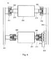
- Figure 4 shows a plain view of another embodiment of the web guide control 10 of the present invention where the adjustment unit consists of a rotating shaft axis 420 and a translation element 411.
- the web tension measurement units 300 are placed at the bearings 431 and 432 of the second guide roller 202.
- the translation element 411 encloses a drive 410, such as a motor, and a moving bearing 415 which can be displaced along the machine frame 452.
- the shaft axis 206 is attached to the moving bearing 415 enclosing the drive 410.
- the rotating shaft axis 420 encloses the shaft axis 205 which is attached with rotational freedom to the machine frame 451.
- Different kind of motors can be used in the adjustment unit of the present invention.
- the distance between the bearings of the two guide rollers 201 and 202 can be adjusted on one side.
- a powered engine is typically used.
- the drive for adjustment is either an electrical or hydraulic motor according to the present invention.
- the position of the moving bearing 415 of the first guide roller 201 is adjusted in such a way that both tension measurement sensors in the second guide 202 roller face the same loading.
- the web tension measurement units consists of a transducer and a strain gauge.
- the transducer consists of a beam which stretches or compresses in response to varying tensions.
- the strain gauge measures the corresponding change in electrical resistance.
- the measurement performed by the strain gauge is amplified and converted to a voltage or current for further processing.
- the web tension measurement units enclose an analogue or digital front end, for further processing of the tension measurement.
- the web tension measurement units are aligned in order to maximize the measurement of the tension in the travelling direction of the web between the first and the second guide rollers.
- the web tension measurement units are mounted in the guide rollers using different options, i.e., between pillow blocks, using cantilevered brackets, using securing via a flange or clamp, using studs, or threaded into through-holes.
- Figure 5 shows a signal flow chart for the web guide control system according to an embodiment of the present invention, which includes a closed-loop controller based on a negative feedback 500 of the transversal tension measurement.
- the closed-loop system maintains an output of the controlled system, e.g. the feedback signal 533, equal to a setpoint 534 value by using previous values of the feedback signal 533 and a control signal 532 fed to the controlled system which is an output of the controller itself.
- the main elements of the flow chart are a controller 501 and a web guide system 502 constituting the web guide control 10 according to the present invention.
- the tension difference between both sides of the second guide roller 202 is the feedback signal 533.
- the setpoint 534 at the controller of the present invention has a null value in order to compensate for tension differences which correspond to transversal tensions acting on the web. Therefore, in typical embodiments of the present invention, the error 531 of the controller exactly corresponds to the tension difference measurement, i.e. the feedback signal 533. In typical embodiments of the present invention the controller compensates deviations from zero of the error 531 using the adjustment unit 310. Typically, this error 531 compensation translates to a distance adjustment of the shaft axes 205 and 215 at one side of both guide rollers 201 and 202. Therefore, the control signal 532, e.g. the controller output, typically corresponds to the distance between the shaft axes at one side of both guide rollers 201 and 202.
- controller 501 different control approaches can be implemented in the controller 501.
- a linear control approach is implemented in the controller 501 choosing from: proportional, integral and derivative (PID) control; proportional and integral (PI) control; proportional and derivative (PD) control; and proportional (P) control.
- PID proportional, integral and derivative
- PI proportional and integral
- PD proportional and derivative
- P proportional
- controllers implemented in the present application can be analogue or digital interfaces including compatibility with transistor-transistor logic (TTL).
- TTL transistor-transistor logic
- digital interfaces works in a discrete manner where the values for the adjustment unit are refreshed after a certain and fixed time period ⁇ t .
- Other special features can be present in controllers of the present invention such as self-tuning, signal computation or filtering, or built-in indicators.
- the feedback signal at a given control step i corresponds to the difference between both tension measurements T i 215 and T i 216 .
- values of D i+ 1 - D i other than zero correspond to a variation in the position at one side of the first guide roller 201. In other embodiments of the present invention, this corresponds to the signal for operation of the drive 410 at the adjustment unit in the first guide roller 201.
Landscapes
- Registering, Tensioning, Guiding Webs, And Rollers Therefor (AREA)
- Controlling Rewinding, Feeding, Winding, Or Abnormalities Of Webs (AREA)
- Supplying Of Containers To The Packaging Station (AREA)
- Electrophonic Musical Instruments (AREA)
- Preliminary Treatment Of Fibers (AREA)
Abstract
Description
- The present invention relates to a web guide control and a web processing apparatus. The present invention relates particularly to a web guide control for compensating failures in the raw material and/or the coiling installation and to a web processing apparatus for coating web in vacuum installations. The present invention also relates to a method for guiding a web and particularly to a method for compensating failures in a web during web guiding.
- Web handling is an important issue in installations for processing continuous web. Therein, many coils handling hundreds of metres or even kilometres of web have to be arranged and operated in such a way that no damage such as crinkles, trumlines, tear-offs, or the like occur in the web.
- It is of course undesirable that failures occur during the web processing such as the web coating. These failures may lead to the total stop of production and/or to the rejection of parts or the entire web treated. In other words, a web guiding malfunction can be very expensive and time consuming.
- In order to avoid malfunctions of a web processing apparatus it is known in the art to provide each guide roll of the web guiding apparatus with a specific tolerance. This way a difference up to e.g. 0.02 mm in the web's thickness along the width of the web can be handled. However, in installations with long coiling length the addition of the guide roller bearing tolerances can cause a tilted feeding in the installation. Further, in vacuum applications very small deviations in thickness can cause complications or failure which would not occur at ambient pressure.
- The problems in the state of the art are at least partly overcome by the web guide control according to claim 1, the web processing apparatus according to
claim 10 and the method for guiding a web according to claim 12. Further aspects, details and advantages are apparent by the dependent claims, the description and the accompanying drawings. - In view of the above, a web guide control for guiding a web is provided. The web guide control includes two guide rollers, an adjustment unit at the first guide roller, a tension measurement unit at the second guide roller, and a data connection for supporting the adjustment unit with tension data from the tension measurement unit.
- According to another aspect of the present invention a web processing apparatus with at least one guide control as described herein is provided.
- According to another aspect of the present invention, a method for guiding a web is provided. The method includes the steps of adjusting the position of a first guide roller by moving one side of the first guide roller and measuring the tension of the web acting on a second guide roller, thereby receiving measurement results, wherein adjusting is based on the measurement results.
- A typical application of web processing apparatuses is the high vacuum web film deposition. For instance, in these applications a protective layer is deposited on a packaging substrate like thin plastic, paper, or metal foil. Thin metal or oxide films may be deposited on the packaging substrate for creating a moisture or oxygen barrier promoting freshness and extending the shelf life of the consumer products which use these films.
- [00010] A further application of a web processing apparatus is the field of manufacturing electronic products. A conductive layer may be deposited on the web serving as conductive coating in applications such as capacitor and touch panels.
- The above features and advantages of the present invention will become more apparent from the following detailed description of preferred embodiments thereof with reference to the attached drawings in which:
- Fig. 1
- shows a schematic diagram of an embodiment of a web processing apparatus according to the present invention.
- Fig. 2
- shows a schematic diagram in a cross-sectional view of the web guide control system according to an embodiment of the present invention.
- Fig. 3
- shows a schematic diagram in a plain section view of the web guide control system according to another embodiment of the present invention.
- Fig. 4
- shows a schematic diagram in a plain section view of the web guide control system according to another embodiment of the present invention.
- Fig. 5
- shows a flow chart of the method for guiding a web according to an embodiment of the present invention.
- Reference will now be made in detail to the various embodiments of the invention, one or more examples of which are illustrated in the figures. Each example is provided by way of explanation of the invention, and is not meant as a limitation of the invention. For example, features illustrated or described as part of one embodiment can be used on or in conjunction with other embodiments to yield yet a further embodiment. It is intended that the present invention includes such modifications and variations.
-
Figure 1 shows an embodiment of a web processing apparatus whereweb guide control 10 according to the present invention is implemented. The web processing apparatus comprises aweb processing unit 100 where aweb 140 is fed to. Further, aweb storage unit 110 is shown where theweb 140 is coiled. Theweb 140 enters theweb processing unit 100 via theinlet port 120. The processedweb 150 is guided out of theweb processing unit 100 through theoutlet port 130. Some installations, in particular at ambient pressure, do not use inlet or outlet port or other units which would be denoted as such. Typically, theweb processing unit 100 comprises one, two, three, or more web guide controls according to the present invention for serial web processing. Synonyms to the term "web" as used within the present application are strip, flexible substrate or the like. - Typically, a web is a three dimensional solid body the thickness of which is in the range up to 1 mm, more typically between 1 µm and 500 µm, and the width of which is between 10 cm and 4,5 m, more typically between 30 cm and 3 m. In typical embodiments, the length of a web is larger than 10 m. Typically, a web consists of a continuous sheet of thin and flexible material. Typical web materials are metals, plastics, paper, or the like.
- According to an embodiment of the present invention, the
web 140 is fed to theweb processing unit 100 from a web supply. Typically, the web supply is aweb storage unit 110 where the web is coiled. Typical lengths of the web on the coil are in the range between 500 m and 50 km. In other embodiments, the web supply is continuous e.g. from a section with or without an outlet port where the web exits the section for being fed to the web processing unit 100 (not shown). Typical guiding velocities are in the range of between 0,1 and 20 metre per second. Typically, different processing steps are performed in theweb processing unit 100 such as cleaning, coating, cooling, heating, or structuring the web. - After the web has been processed in the
web processing unit 100, the processedweb 150 exits theweb processing unit 100 at theoutlet port 130. Typically, the processedweb 150 is fed to a second processing unit or guided out for storage. - Typically, a web processing apparatus comprising one or more web guide controls according to the present invention may be used for guiding a web in various applications. This web processing apparatus is particularly suitable for challenging webs such as a metal web, in particular aluminium web, and thin plastic web. Thin web in this context is meant to be understood as having a thickness of between 1 µm and 200 µm, in particular between 30 µm and 140 µm.
-
Figure 2 shows a cross-sectional view of an embodiment of theweb guide control 10 of the present invention. Theweb guide control 10 comprises afirst guide roller 201 with itscorresponding shaft axis 205 and asecond guide roller 202 with itscorresponding shaft axis 215. Theweb 140 is guided through thefirst guide roller 201 and thesecond guide roller 202. Theweb 140 may be unprocessed or have already undergone one or more processing steps. Typically thefirst guide roller 201 is positioned upstream of thesecond guide roller 202. The terms "downstream" and "upstream" within the present application are to be understood with respect to the travelling direction of the web. Theweb guide control 10 of the present invention is not exclusively limited to the implementation in web processing apparatus. For example, the web guide control can also be implemented in manufacturing plants where web transport is required. In principal, it is also possible to position thefirst guide roller 201 downstream of thesecond guide roller 202. - According to the present invention the distance between both
shaft axes rollers second guide roller 202. Typically, the measurement sensor is adapted for measuring tensions of between 0 and 400 N/m. Typically this distance is adjusted using an adjustment unit placed at one side of thefirst guide roller 201. The "side" of the roller is to be understood as the position at or close to the end of the roller or its axis. Typical diameters of guide rollers used in the present invention are between 65 mm and 300 mm. - The advantage of using a two roller system for measurement and adjustment instead of a single roller system is, for example, a better handling of vibrations caused by the control loop.
- In principle the adjustment unit may be applied for alignment of the guide rollers required to avoid transversal tension acting on the web. Typically the
web guide control 10 of the present invention is particularly useful for compensating different coiling strengths at theguide rollers - In some embodiments of the present invention, the
first guide roller 201 and/or thesecond guide roller 202 are cooling or heater rollers. Alternatively, or in addition, there might be positioned a further cooling or heater guide roller in between thefirst guide roller 201 and thesecond guide roller 202, upstream of the first andsecond guide roller -
Figure 3 shows a plain view of a typical embodiment of the present invention. The different elements of this embodiment forming part of the transversal web tension adjustment are shown in the figure: anadjustment unit 310 at thefirst guide roller 201, a webtension measurement unit 300 at thesecond guide roller 202, and adata connection 330 between both guiderollers adjustment unit 310. Typically, thefirst guide roller 201 is positioned upstream of thesecond guide roller 202. - The
data connection 330 is used to transmit information from the measurement unit to theadjustment unit 310. Thedata connection 330 can also be used to transmit information from theadjustment unit 310 to an external interface. Typically this interface consists of a personal computer which processes the data from theadjustment unit 310. Also the interface can consist of an analogue front panel comprising different element to tune theadjustment unit 310, i.e. using different potentiometers, dials, switches, and displays. Further, the interface can also consist of a digital device including numeric pads, graphical display, text commands, or a graphical user interface. Typically, all these interfaces include different features such as controller function, calibration of the system, compensation of ambient conditions, or acquisition and recording of waveforms from thetension unit 300 or theadjustment unit 310. - For connecting the
data connection 330 to the different devices, different port types are used. Typically, when serial communication is used, the ports are RS232, RS422, RS485, or universal serial bus (USB) ports. Typically, parallel communication devices are used when communication between thedata connection 330 and a computer is required. Most often used parallel communication devices are DB-25, Centronics 36, SPP, EPP or ECP parallel ports. Thedata connection 330 can be used to make theadjustment unit 310 compatible with transistor-transistor logic (TTL) or with programmable logic controllers (PLC). Additionally thedata connection 330 can be used to connect theadjustment unit 310 with a network. - According to an embodiment of the present invention the tension acting on both
shaft axes second guide roller 202 will be acquired separately. The acquired data will be processed and sent to theadjustment unit 310 in thefirst guide roller 201. Theadjustment unit 310 adjusts the position of the shaft axis at one side of thefirst guide roller 201. Thereby, the distance between the shaft axes of the first guide roller and the shaft axes of the second guide roller is adjusted. Theadjustment unit 300 is operated in order to equalize the tension measured between the shaft axes at both sides of thesecond guide roller 202. It is, however, also possible to adjust the position of the shaft axis on both sides of the first guide roller 201 (not shown in drawings). -
Figure 4 shows a plain view of another embodiment of theweb guide control 10 of the present invention where the adjustment unit consists of arotating shaft axis 420 and atranslation element 411. The webtension measurement units 300 are placed at thebearings second guide roller 202. Typically thetranslation element 411 encloses adrive 410, such as a motor, and a movingbearing 415 which can be displaced along themachine frame 452. Theshaft axis 206 is attached to the movingbearing 415 enclosing thedrive 410. Therotating shaft axis 420 encloses theshaft axis 205 which is attached with rotational freedom to themachine frame 451. - Different kind of motors can be used in the adjustment unit of the present invention. At the
first guide roller 201 the distance between the bearings of the twoguide rollers bearing 415 of thefirst guide roller 201 is adjusted in such a way that both tension measurement sensors in thesecond guide 202 roller face the same loading. - In typical embodiments of the present invention the web tension measurement units consists of a transducer and a strain gauge. Typically the transducer consists of a beam which stretches or compresses in response to varying tensions. The strain gauge measures the corresponding change in electrical resistance. Typically, the measurement performed by the strain gauge is amplified and converted to a voltage or current for further processing. In general, the web tension measurement units enclose an analogue or digital front end, for further processing of the tension measurement. Typically, the web tension measurement units are aligned in order to maximize the measurement of the tension in the travelling direction of the web between the first and the second guide rollers. Typically, the web tension measurement units are mounted in the guide rollers using different options, i.e., between pillow blocks, using cantilevered brackets, using securing via a flange or clamp, using studs, or threaded into through-holes.
-
Figure 5 shows a signal flow chart for the web guide control system according to an embodiment of the present invention, which includes a closed-loop controller based on anegative feedback 500 of the transversal tension measurement. The closed-loop system maintains an output of the controlled system, e.g. thefeedback signal 533, equal to asetpoint 534 value by using previous values of thefeedback signal 533 and acontrol signal 532 fed to the controlled system which is an output of the controller itself. The main elements of the flow chart are acontroller 501 and aweb guide system 502 constituting theweb guide control 10 according to the present invention. The tension difference between both sides of thesecond guide roller 202 is thefeedback signal 533. Typically, thesetpoint 534 at the controller of the present invention has a null value in order to compensate for tension differences which correspond to transversal tensions acting on the web. Therefore, in typical embodiments of the present invention, theerror 531 of the controller exactly corresponds to the tension difference measurement, i.e. thefeedback signal 533. In typical embodiments of the present invention the controller compensates deviations from zero of theerror 531 using theadjustment unit 310. Typically, thiserror 531 compensation translates to a distance adjustment of the shaft axes 205 and 215 at one side of both guiderollers control signal 532, e.g. the controller output, typically corresponds to the distance between the shaft axes at one side of both guiderollers - In principle, different control approaches can be implemented in the
controller 501. Typically, a linear control approach is implemented in thecontroller 501 choosing from: proportional, integral and derivative (PID) control; proportional and integral (PI) control; proportional and derivative (PD) control; and proportional (P) control. However, also other advanced controls using non-linear control approaches may be implemented in embodiments of the present invention, e.g. adaptive gain, dead-time compensation, fuzzy logic, neural networks, or feed-forward control. Controllers implemented in the present application can be analogue or digital interfaces including compatibility with transistor-transistor logic (TTL). Typically, digital interfaces works in a discrete manner where the values for the adjustment unit are refreshed after a certain and fixed time period Δt. Other special features can be present in controllers of the present invention such as self-tuning, signal computation or filtering, or built-in indicators. - As illustration of the functioning of a controller according to an embodiment of the present invention, in the following the implementation of a discrete PID controller is described. The feedback signal at a given control step i corresponds to the difference between both tension measurements


second guide roller 202 should be equal. Therefore, the error signal at a given processing step i corresponds to

where the first term corresponds to the integral part of the controller, the second to the proportional, and the third to the derivative. Kp is the proportional band and Kd is the derivative gain. Typically, values of D i+1 - Di other than zero correspond to a variation in the position at one side of thefirst guide roller 201. In other embodiments of the present invention, this corresponds to the signal for operation of thedrive 410 at the adjustment unit in thefirst guide roller 201. - This written description uses examples to disclose the invention, including the best mode, and also to enable any person skilled in the art to make and use the invention. While the invention has been described in terms of various specific embodiments, those skilled in the art will recognize that the invention can be practiced with modification within the spirit and scope of the claims. Especially, mutually non-exclusive features of the embodiments described above may be combined with each other. The patentable scope of the invention is defined by the claims, and may include other examples that occur to those skilled in the art. Such other examples are intended to be within the scope of the claims of they have structural elements that do not differ from the literal language of the claims, or if they include equivalent structural elements with insubstantial differences from the literal languages of the claims.
Claims (16)
- A web guide control for guiding a web, the web guide control having a first guide roller (201), and a second guide roller (202) wherein- the first guide roller comprises an adjustment unit (310);- the second guide roller comprises a tension measurement unit (300); and- the web guide control comprises a data connection (330) for supporting the adjustment unit with tension data from the tension measurement unit.
- The web guide control according to claim 1 wherein the tension measurement unit (300) comprises a first tension sensor positioned at a first side of the second guide roller (202).
- The web guide control according to claim 1 wherein the tension measurement unit (310) comprises a second tension sensor positioned at a second side of the second guide roller (202).
- The web guide control according to any of the preceding claims wherein the adjustment unit (310) comprises a motor for moving the first guide roller positioned at one side of the first guide roller.
- The web guide control according to any of the preceding claims wherein the adjustment unit is controlled using a closed-loop controller and the tension data is used as variable feedback signal.
- The web guide control according to claim 5 wherein the closed-loop comprises analogue electronics.
- The web guide control according to claim 5 wherein the closed-loop comprises digital electronics.
- The web guide control according to any of the preceding claims wherein the first guide roller is positioned upstream of the second guide roller with respect to the web guiding direction.
- The web guide control according to any of the claims 1-7 wherein the first guide roller is positioned downstream of the second guide roller with respect to the web guiding direction.
- A web processing apparatus having at least one web guide control according to any of the preceding claims.
- The web processing apparatus according to claim 10, further comprising a coating unit for coating the web.
- A method for guiding a web comprising the steps of:- adjusting the position of a first guide roller by moving one side of the first guide roller;- measuring the tension of the web acting on a second guide roller, thereby receiving measurement results; and- wherein adjusting is based on the measurement results.
- The method according to claim 12 wherein the measuring is undertaken at a first side of a second guide roller and at a second side of the second guide roller.
- The method according to any of claims 12-13 wherein the adjusting is undertaken at one side of the first guide roller.
- The web guide control according to any of claims 12-14 wherein the measuring is undertaken upstream of the adjusting with respect to the web guiding direction.
- The web guide control according to any of claims 12-14 wherein the measuring is undertaken downstream of the adjusting with respect to the web guiding direction.
Priority Applications (8)
| Application Number | Priority Date | Filing Date | Title |
|---|---|---|---|
| DE602007005973T DE602007005973D1 (en) | 2007-02-28 | 2007-02-28 | Network control, network processing device and operating method therefor |
| EP07004189A EP1964799B1 (en) | 2007-02-28 | 2007-02-28 | Web guide control, web processing apparatus and method for operating the same |
| AT07004189T ATE465112T1 (en) | 2007-02-28 | 2007-02-28 | NETWORK MANAGEMENT CONTROLLER, NETWORK PROCESSING DEVICE AND OPERATING METHOD THEREOF |
| TW097106673A TWI379016B (en) | 2007-02-28 | 2008-02-26 | Web guide control, web processing apparatus and method for operating the same |
| KR1020097020108A KR20090115971A (en) | 2007-02-28 | 2008-02-28 | Web guide control, web processing unit and its operation method |
| US12/528,789 US20100038468A1 (en) | 2007-02-28 | 2008-02-28 | Web guide control, web processing apparatus and method for operating the same |
| PCT/EP2008/052438 WO2008104593A1 (en) | 2007-02-28 | 2008-02-28 | Web guide control, web processing apparatus and method for operating the same |
| JP2009551934A JP2010520131A (en) | 2007-02-28 | 2008-02-28 | Web guide control, web processing apparatus, and operation method thereof |
Applications Claiming Priority (1)
| Application Number | Priority Date | Filing Date | Title |
|---|---|---|---|
| EP07004189A EP1964799B1 (en) | 2007-02-28 | 2007-02-28 | Web guide control, web processing apparatus and method for operating the same |
Publications (2)
| Publication Number | Publication Date |
|---|---|
| EP1964799A1 true EP1964799A1 (en) | 2008-09-03 |
| EP1964799B1 EP1964799B1 (en) | 2010-04-21 |
Family
ID=38267575
Family Applications (1)
| Application Number | Title | Priority Date | Filing Date |
|---|---|---|---|
| EP07004189A Not-in-force EP1964799B1 (en) | 2007-02-28 | 2007-02-28 | Web guide control, web processing apparatus and method for operating the same |
Country Status (8)
| Country | Link |
|---|---|
| US (1) | US20100038468A1 (en) |
| EP (1) | EP1964799B1 (en) |
| JP (1) | JP2010520131A (en) |
| KR (1) | KR20090115971A (en) |
| AT (1) | ATE465112T1 (en) |
| DE (1) | DE602007005973D1 (en) |
| TW (1) | TWI379016B (en) |
| WO (1) | WO2008104593A1 (en) |
Cited By (4)
| Publication number | Priority date | Publication date | Assignee | Title |
|---|---|---|---|---|
| WO2013179561A1 (en) * | 2012-05-31 | 2013-12-05 | Sony Corporation | Film-forming apparatus and film-forming method |
| US20140209731A1 (en) * | 2013-01-31 | 2014-07-31 | Applied Materials, Inc. | Web guide control unit, web processing apparatus and method for operating the same |
| EP2684825A3 (en) * | 2012-07-12 | 2016-04-06 | Tsudakoma Kogyo Kabushiki Kaisha | Sheet material supplying device |
| CN113258240A (en) * | 2021-05-19 | 2021-08-13 | 东南大学 | Nonlinear artificial SPP waveguide for parametric amplification of multi-frequency signal waves and calculation method |
Families Citing this family (10)
| Publication number | Priority date | Publication date | Assignee | Title |
|---|---|---|---|---|
| US8554354B1 (en) * | 2010-02-12 | 2013-10-08 | The Board Of Regents For Oklahoma State University | Method for adaptive guiding of webs |
| JP5880808B2 (en) * | 2011-04-21 | 2016-03-09 | 東洋製罐株式会社 | Bag making equipment |
| KR102083960B1 (en) * | 2012-08-30 | 2020-03-03 | 엘지전자 주식회사 | Method for manufacturing graphene and the graphene manufactured by the same and the manufacturing apparatus |
| JP2016008326A (en) * | 2014-06-25 | 2016-01-18 | 東レエンジニアリング株式会社 | Substrate transferring and processing apparatus |
| WO2016208022A1 (en) * | 2015-06-25 | 2016-12-29 | 株式会社ニレコ | Web meandering control device and control method |
| CN106847499B (en) * | 2016-12-30 | 2018-06-08 | 郑州大学综合设计研究院有限公司 | A kind of capacitor core coiler device |
| CN106601390B (en) * | 2016-12-30 | 2017-12-19 | 嵊州北航投星空众创科技有限公司 | A kind of capacitor core coiler device with mobile tension regulating function |
| JP7115820B2 (en) * | 2017-03-13 | 2022-08-09 | 王子ホールディングス株式会社 | TENSION ADJUSTMENT DEVICE AND TENSION ADJUSTMENT METHOD USED IN APPARATUS FOR MANUFACTURING ABSORBENT ARTICLES |
| US20220002107A1 (en) * | 2020-07-01 | 2022-01-06 | CSG Holding, Inc. | Webtension transducer load cell with integrated data interface |
| EP4334228A4 (en) * | 2021-05-06 | 2025-04-16 | Applied Materials, Inc. | CROSS BELT TENSION MEASUREMENT AND CONTROL |
Citations (4)
| Publication number | Priority date | Publication date | Assignee | Title |
|---|---|---|---|---|
| DE9108408U1 (en) * | 1991-07-08 | 1991-08-29 | H. Krantz Textiltechnik GmbH, 52070 Aachen | Device for eliminating skew distortions in a running web |
| EP0579854A1 (en) * | 1992-07-22 | 1994-01-26 | Kawasaki Steel Corporation | Strip tension control apparatus |
| US5419509A (en) * | 1993-05-12 | 1995-05-30 | Krayenhagen; Everett D. | Web tensioning device for automatic cross-machine tensioning of continuous webs |
| EP1288150A2 (en) * | 2001-08-24 | 2003-03-05 | Goss International Corporation | Tension control device for a printing press |
Family Cites Families (8)
| Publication number | Priority date | Publication date | Assignee | Title |
|---|---|---|---|---|
| US4347993A (en) * | 1979-11-06 | 1982-09-07 | W. J. Industries, Incorporated | Tension monitor means and system |
| JPH0361248A (en) * | 1989-07-31 | 1991-03-18 | Toshiba Chem Corp | Left and right tension compensating apparatus for long-length film |
| EP0761583B1 (en) * | 1995-08-30 | 2002-10-23 | Goss Graphic Systems, Inc. | Tension control device for a printing press |
| DE19960649B4 (en) * | 1999-12-16 | 2011-06-22 | Goss Contiweb B.V. | Device for correcting the lateral position of a printing material web in a web-fed rotary printing press |
| US6547707B2 (en) * | 2001-01-10 | 2003-04-15 | Heidelberger Druckmaschinen Ag | Strain control in an infeed of a printing machine |
| US6659323B2 (en) * | 2002-01-30 | 2003-12-09 | Presstek, Inc. | Methods and apparatus for prescribing web tracking in processing equipment |
| US7438251B2 (en) * | 2003-06-19 | 2008-10-21 | Specialty Systems Advanced Machinery, Inc. | Web tensioning device with plural control inputs |
| JP4079161B2 (en) * | 2005-05-24 | 2008-04-23 | 松下電工株式会社 | Prepreg manufacturing apparatus and manufacturing method |
-
2007
- 2007-02-28 DE DE602007005973T patent/DE602007005973D1/en active Active
- 2007-02-28 EP EP07004189A patent/EP1964799B1/en not_active Not-in-force
- 2007-02-28 AT AT07004189T patent/ATE465112T1/en not_active IP Right Cessation
-
2008
- 2008-02-26 TW TW097106673A patent/TWI379016B/en not_active IP Right Cessation
- 2008-02-28 WO PCT/EP2008/052438 patent/WO2008104593A1/en not_active Ceased
- 2008-02-28 JP JP2009551934A patent/JP2010520131A/en active Pending
- 2008-02-28 US US12/528,789 patent/US20100038468A1/en not_active Abandoned
- 2008-02-28 KR KR1020097020108A patent/KR20090115971A/en not_active Withdrawn
Patent Citations (4)
| Publication number | Priority date | Publication date | Assignee | Title |
|---|---|---|---|---|
| DE9108408U1 (en) * | 1991-07-08 | 1991-08-29 | H. Krantz Textiltechnik GmbH, 52070 Aachen | Device for eliminating skew distortions in a running web |
| EP0579854A1 (en) * | 1992-07-22 | 1994-01-26 | Kawasaki Steel Corporation | Strip tension control apparatus |
| US5419509A (en) * | 1993-05-12 | 1995-05-30 | Krayenhagen; Everett D. | Web tensioning device for automatic cross-machine tensioning of continuous webs |
| EP1288150A2 (en) * | 2001-08-24 | 2003-03-05 | Goss International Corporation | Tension control device for a printing press |
Cited By (10)
| Publication number | Priority date | Publication date | Assignee | Title |
|---|---|---|---|---|
| WO2013179561A1 (en) * | 2012-05-31 | 2013-12-05 | Sony Corporation | Film-forming apparatus and film-forming method |
| CN104603326A (en) * | 2012-05-31 | 2015-05-06 | 索尼公司 | Film-forming apparatus and film-forming method |
| US9738969B2 (en) | 2012-05-31 | 2017-08-22 | Sony Corporation | Film-forming apparatus and film-forming method |
| EP2684825A3 (en) * | 2012-07-12 | 2016-04-06 | Tsudakoma Kogyo Kabushiki Kaisha | Sheet material supplying device |
| US20140209731A1 (en) * | 2013-01-31 | 2014-07-31 | Applied Materials, Inc. | Web guide control unit, web processing apparatus and method for operating the same |
| EP2762431A1 (en) * | 2013-01-31 | 2014-08-06 | Applied Materials, Inc. | Web guide control unit, web processing apparatus and method for operating the same |
| WO2014118064A1 (en) * | 2013-01-31 | 2014-08-07 | Applied Materials, Inc. | Web guide control unit, web processing apparatus and method for operating the same |
| US9206008B2 (en) * | 2013-01-31 | 2015-12-08 | Applied Materials, Inc. | Web guide control unit, web processing apparatus and method for operating the same |
| TWI552942B (en) * | 2013-01-31 | 2016-10-11 | 應用材料股份有限公司 | Web guide control unit, web processing apparatus and method for operating the same |
| CN113258240A (en) * | 2021-05-19 | 2021-08-13 | 东南大学 | Nonlinear artificial SPP waveguide for parametric amplification of multi-frequency signal waves and calculation method |
Also Published As
| Publication number | Publication date |
|---|---|
| TW200848539A (en) | 2008-12-16 |
| EP1964799B1 (en) | 2010-04-21 |
| ATE465112T1 (en) | 2010-05-15 |
| WO2008104593A1 (en) | 2008-09-04 |
| TWI379016B (en) | 2012-12-11 |
| KR20090115971A (en) | 2009-11-10 |
| US20100038468A1 (en) | 2010-02-18 |
| DE602007005973D1 (en) | 2010-06-02 |
| JP2010520131A (en) | 2010-06-10 |
Similar Documents
| Publication | Publication Date | Title |
|---|---|---|
| EP1964799B1 (en) | Web guide control, web processing apparatus and method for operating the same | |
| EP2762431B1 (en) | Web guide control unit, web processing apparatus and method for operating the same | |
| EP1701903B1 (en) | Real-time determination of web tension and control using position sensors | |
| EP0216964A1 (en) | Take-out/take-up tension control apparatus | |
| WO2009122836A1 (en) | Production equipment and method of thin-film laminate | |
| US5553805A (en) | Process and apparatus for winding sheet material | |
| CN109573700B (en) | Tension control method and tension control system | |
| CA2553357C (en) | Media registration systems and methods | |
| CN103086178B (en) | A kind of winder and the method controlling flexible material rolling | |
| CN103086180B (en) | A kind of unreeling machine and control flexible materials put the method for volume | |
| JP5894841B2 (en) | Unwinding roll control device and control method thereof | |
| CN223702143U (en) | Embossing correction mechanism and pole piece processing device | |
| EP1633666B1 (en) | Method and apparatus for unwinding a roll of web material | |
| Damour et al. | The mechanics of tension control | |
| JPH05116824A (en) | Tension control device for sheet-like material | |
| KR810001346B1 (en) | Winding tension control method | |
| CN222990203U (en) | Tension control system and vacuum coating equipment | |
| CN120817483A (en) | A contact pressure precision control device and control method for lithium battery diaphragm slitting machine | |
| JP2026058923A (en) | Coating control device, coating device, roller deformation detection device, coating method, roller deformation detection method | |
| CN121849736A (en) | Winding and unwinding tension control device and method for winding transformer sleeve | |
| CN118907945A (en) | High-speed continuous transfer film conveying device based on tension control | |
| CN115922841A (en) | Paper roll punching machine with automatically adjusted reverse bending and punching method | |
| Chen et al. | Tension/Position Hybrid Control of a Web-Conveyed System | |
| JPH03158345A (en) | Drawing-out gap correcting mechanism of paper |
Legal Events
| Date | Code | Title | Description |
|---|---|---|---|
| PUAI | Public reference made under article 153(3) epc to a published international application that has entered the european phase |
Free format text: ORIGINAL CODE: 0009012 |
|
| AK | Designated contracting states |
Kind code of ref document: A1 Designated state(s): AT BE BG CH CY CZ DE DK EE ES FI FR GB GR HU IE IS IT LI LT LU LV MC NL PL PT RO SE SI SK TR |
|
| AX | Request for extension of the european patent |
Extension state: AL BA HR MK RS |
|
| 17P | Request for examination filed |
Effective date: 20081127 |
|
| AKX | Designation fees paid |
Designated state(s): AT BE BG CH CY CZ DE DK EE ES FI FR GB GR HU IE IS IT LI LT LU LV MC NL PL PT RO SE SI SK TR |
|
| 17Q | First examination report despatched |
Effective date: 20090826 |
|
| GRAP | Despatch of communication of intention to grant a patent |
Free format text: ORIGINAL CODE: EPIDOSNIGR1 |
|
| GRAS | Grant fee paid |
Free format text: ORIGINAL CODE: EPIDOSNIGR3 |
|
| GRAA | (expected) grant |
Free format text: ORIGINAL CODE: 0009210 |
|
| AK | Designated contracting states |
Kind code of ref document: B1 Designated state(s): AT BE BG CH CY CZ DE DK EE ES FI FR GB GR HU IE IS IT LI LT LU LV MC NL PL PT RO SE SI SK TR |
|
| REG | Reference to a national code |
Ref country code: GB Ref legal event code: FG4D |
|
| REG | Reference to a national code |
Ref country code: CH Ref legal event code: EP |
|
| REG | Reference to a national code |
Ref country code: IE Ref legal event code: FG4D |
|
| REF | Corresponds to: |
Ref document number: 602007005973 Country of ref document: DE Date of ref document: 20100602 Kind code of ref document: P |
|
| REG | Reference to a national code |
Ref country code: NL Ref legal event code: VDEP Effective date: 20100421 |
|
| LTIE | Lt: invalidation of european patent or patent extension |
Effective date: 20100421 |
|
| PG25 | Lapsed in a contracting state [announced via postgrant information from national office to epo] |
Ref country code: NL Free format text: LAPSE BECAUSE OF FAILURE TO SUBMIT A TRANSLATION OF THE DESCRIPTION OR TO PAY THE FEE WITHIN THE PRESCRIBED TIME-LIMIT Effective date: 20100421 Ref country code: LT Free format text: LAPSE BECAUSE OF FAILURE TO SUBMIT A TRANSLATION OF THE DESCRIPTION OR TO PAY THE FEE WITHIN THE PRESCRIBED TIME-LIMIT Effective date: 20100421 Ref country code: SE Free format text: LAPSE BECAUSE OF FAILURE TO SUBMIT A TRANSLATION OF THE DESCRIPTION OR TO PAY THE FEE WITHIN THE PRESCRIBED TIME-LIMIT Effective date: 20100421 Ref country code: ES Free format text: LAPSE BECAUSE OF FAILURE TO SUBMIT A TRANSLATION OF THE DESCRIPTION OR TO PAY THE FEE WITHIN THE PRESCRIBED TIME-LIMIT Effective date: 20100801 |
|
| PG25 | Lapsed in a contracting state [announced via postgrant information from national office to epo] |
Ref country code: FI Free format text: LAPSE BECAUSE OF FAILURE TO SUBMIT A TRANSLATION OF THE DESCRIPTION OR TO PAY THE FEE WITHIN THE PRESCRIBED TIME-LIMIT Effective date: 20100421 Ref country code: SI Free format text: LAPSE BECAUSE OF FAILURE TO SUBMIT A TRANSLATION OF THE DESCRIPTION OR TO PAY THE FEE WITHIN THE PRESCRIBED TIME-LIMIT Effective date: 20100421 Ref country code: LV Free format text: LAPSE BECAUSE OF FAILURE TO SUBMIT A TRANSLATION OF THE DESCRIPTION OR TO PAY THE FEE WITHIN THE PRESCRIBED TIME-LIMIT Effective date: 20100421 Ref country code: IS Free format text: LAPSE BECAUSE OF FAILURE TO SUBMIT A TRANSLATION OF THE DESCRIPTION OR TO PAY THE FEE WITHIN THE PRESCRIBED TIME-LIMIT Effective date: 20100821 Ref country code: AT Free format text: LAPSE BECAUSE OF FAILURE TO SUBMIT A TRANSLATION OF THE DESCRIPTION OR TO PAY THE FEE WITHIN THE PRESCRIBED TIME-LIMIT Effective date: 20100421 |
|
| PG25 | Lapsed in a contracting state [announced via postgrant information from national office to epo] |
Ref country code: CY Free format text: LAPSE BECAUSE OF FAILURE TO SUBMIT A TRANSLATION OF THE DESCRIPTION OR TO PAY THE FEE WITHIN THE PRESCRIBED TIME-LIMIT Effective date: 20100602 Ref country code: PL Free format text: LAPSE BECAUSE OF FAILURE TO SUBMIT A TRANSLATION OF THE DESCRIPTION OR TO PAY THE FEE WITHIN THE PRESCRIBED TIME-LIMIT Effective date: 20100421 |
|
| PG25 | Lapsed in a contracting state [announced via postgrant information from national office to epo] |
Ref country code: DK Free format text: LAPSE BECAUSE OF FAILURE TO SUBMIT A TRANSLATION OF THE DESCRIPTION OR TO PAY THE FEE WITHIN THE PRESCRIBED TIME-LIMIT Effective date: 20100421 Ref country code: PT Free format text: LAPSE BECAUSE OF FAILURE TO SUBMIT A TRANSLATION OF THE DESCRIPTION OR TO PAY THE FEE WITHIN THE PRESCRIBED TIME-LIMIT Effective date: 20100823 Ref country code: GR Free format text: LAPSE BECAUSE OF FAILURE TO SUBMIT A TRANSLATION OF THE DESCRIPTION OR TO PAY THE FEE WITHIN THE PRESCRIBED TIME-LIMIT Effective date: 20100722 Ref country code: EE Free format text: LAPSE BECAUSE OF FAILURE TO SUBMIT A TRANSLATION OF THE DESCRIPTION OR TO PAY THE FEE WITHIN THE PRESCRIBED TIME-LIMIT Effective date: 20100421 |
|
| PLBE | No opposition filed within time limit |
Free format text: ORIGINAL CODE: 0009261 |
|
| STAA | Information on the status of an ep patent application or granted ep patent |
Free format text: STATUS: NO OPPOSITION FILED WITHIN TIME LIMIT |
|
| PG25 | Lapsed in a contracting state [announced via postgrant information from national office to epo] |
Ref country code: RO Free format text: LAPSE BECAUSE OF FAILURE TO SUBMIT A TRANSLATION OF THE DESCRIPTION OR TO PAY THE FEE WITHIN THE PRESCRIBED TIME-LIMIT Effective date: 20100421 Ref country code: BE Free format text: LAPSE BECAUSE OF FAILURE TO SUBMIT A TRANSLATION OF THE DESCRIPTION OR TO PAY THE FEE WITHIN THE PRESCRIBED TIME-LIMIT Effective date: 20100421 Ref country code: CZ Free format text: LAPSE BECAUSE OF FAILURE TO SUBMIT A TRANSLATION OF THE DESCRIPTION OR TO PAY THE FEE WITHIN THE PRESCRIBED TIME-LIMIT Effective date: 20100421 Ref country code: SK Free format text: LAPSE BECAUSE OF FAILURE TO SUBMIT A TRANSLATION OF THE DESCRIPTION OR TO PAY THE FEE WITHIN THE PRESCRIBED TIME-LIMIT Effective date: 20100421 |
|
| 26N | No opposition filed |
Effective date: 20110124 |
|
| PG25 | Lapsed in a contracting state [announced via postgrant information from national office to epo] |
Ref country code: MC Free format text: LAPSE BECAUSE OF NON-PAYMENT OF DUE FEES Effective date: 20110228 |
|
| REG | Reference to a national code |
Ref country code: CH Ref legal event code: PL |
|
| PG25 | Lapsed in a contracting state [announced via postgrant information from national office to epo] |
Ref country code: CH Free format text: LAPSE BECAUSE OF NON-PAYMENT OF DUE FEES Effective date: 20110228 Ref country code: LI Free format text: LAPSE BECAUSE OF NON-PAYMENT OF DUE FEES Effective date: 20110228 |
|
| REG | Reference to a national code |
Ref country code: FR Ref legal event code: ST Effective date: 20111102 |
|
| REG | Reference to a national code |
Ref country code: IE Ref legal event code: MM4A |
|
| PG25 | Lapsed in a contracting state [announced via postgrant information from national office to epo] |
Ref country code: IE Free format text: LAPSE BECAUSE OF NON-PAYMENT OF DUE FEES Effective date: 20110228 Ref country code: FR Free format text: LAPSE BECAUSE OF NON-PAYMENT OF DUE FEES Effective date: 20110228 |
|
| PGFP | Annual fee paid to national office [announced via postgrant information from national office to epo] |
Ref country code: DE Payment date: 20120221 Year of fee payment: 6 |
|
| PGFP | Annual fee paid to national office [announced via postgrant information from national office to epo] |
Ref country code: GB Payment date: 20120221 Year of fee payment: 6 Ref country code: IT Payment date: 20120224 Year of fee payment: 6 |
|
| PG25 | Lapsed in a contracting state [announced via postgrant information from national office to epo] |
Ref country code: LU Free format text: LAPSE BECAUSE OF NON-PAYMENT OF DUE FEES Effective date: 20110228 |
|
| PG25 | Lapsed in a contracting state [announced via postgrant information from national office to epo] |
Ref country code: TR Free format text: LAPSE BECAUSE OF FAILURE TO SUBMIT A TRANSLATION OF THE DESCRIPTION OR TO PAY THE FEE WITHIN THE PRESCRIBED TIME-LIMIT Effective date: 20100421 Ref country code: BG Free format text: LAPSE BECAUSE OF FAILURE TO SUBMIT A TRANSLATION OF THE DESCRIPTION OR TO PAY THE FEE WITHIN THE PRESCRIBED TIME-LIMIT Effective date: 20100721 |
|
| GBPC | Gb: european patent ceased through non-payment of renewal fee |
Effective date: 20130228 |
|
| PG25 | Lapsed in a contracting state [announced via postgrant information from national office to epo] |
Ref country code: HU Free format text: LAPSE BECAUSE OF FAILURE TO SUBMIT A TRANSLATION OF THE DESCRIPTION OR TO PAY THE FEE WITHIN THE PRESCRIBED TIME-LIMIT Effective date: 20100421 |
|
| REG | Reference to a national code |
Ref country code: DE Ref legal event code: R119 Ref document number: 602007005973 Country of ref document: DE Effective date: 20130903 |
|
| PG25 | Lapsed in a contracting state [announced via postgrant information from national office to epo] |
Ref country code: IT Free format text: LAPSE BECAUSE OF NON-PAYMENT OF DUE FEES Effective date: 20130228 |
|
| PG25 | Lapsed in a contracting state [announced via postgrant information from national office to epo] |
Ref country code: GB Free format text: LAPSE BECAUSE OF NON-PAYMENT OF DUE FEES Effective date: 20130228 Ref country code: DE Free format text: LAPSE BECAUSE OF NON-PAYMENT OF DUE FEES Effective date: 20130903 |