JP2010520131A - Web guide control, web processing apparatus, and operation method thereof - Google Patents
Web guide control, web processing apparatus, and operation method thereof Download PDFInfo
- Publication number
- JP2010520131A JP2010520131A JP2009551934A JP2009551934A JP2010520131A JP 2010520131 A JP2010520131 A JP 2010520131A JP 2009551934 A JP2009551934 A JP 2009551934A JP 2009551934 A JP2009551934 A JP 2009551934A JP 2010520131 A JP2010520131 A JP 2010520131A
- Authority
- JP
- Japan
- Prior art keywords
- web
- guide roller
- guide
- tension
- control
- Prior art date
- Legal status (The legal status is an assumption and is not a legal conclusion. Google has not performed a legal analysis and makes no representation as to the accuracy of the status listed.)
- Pending
Links
Images

Classifications
-
- B—PERFORMING OPERATIONS; TRANSPORTING
- B65—CONVEYING; PACKING; STORING; HANDLING THIN OR FILAMENTARY MATERIAL
- B65H—HANDLING THIN OR FILAMENTARY MATERIAL, e.g. SHEETS, WEBS, CABLES
- B65H23/00—Registering, tensioning, smoothing or guiding webs
- B65H23/04—Registering, tensioning, smoothing or guiding webs longitudinally
- B65H23/044—Sensing web tension
-
- B—PERFORMING OPERATIONS; TRANSPORTING
- B65—CONVEYING; PACKING; STORING; HANDLING THIN OR FILAMENTARY MATERIAL
- B65H—HANDLING THIN OR FILAMENTARY MATERIAL, e.g. SHEETS, WEBS, CABLES
- B65H23/00—Registering, tensioning, smoothing or guiding webs
- B65H23/02—Registering, tensioning, smoothing or guiding webs transversely
- B65H23/0204—Sensing transverse register of web
-
- B—PERFORMING OPERATIONS; TRANSPORTING
- B65—CONVEYING; PACKING; STORING; HANDLING THIN OR FILAMENTARY MATERIAL
- B65H—HANDLING THIN OR FILAMENTARY MATERIAL, e.g. SHEETS, WEBS, CABLES
- B65H23/00—Registering, tensioning, smoothing or guiding webs
- B65H23/04—Registering, tensioning, smoothing or guiding webs longitudinally
- B65H23/18—Registering, tensioning, smoothing or guiding webs longitudinally by controlling or regulating the web-advancing mechanism, e.g. mechanism acting on the running web
- B65H23/188—Registering, tensioning, smoothing or guiding webs longitudinally by controlling or regulating the web-advancing mechanism, e.g. mechanism acting on the running web in connection with running-web
- B65H23/1888—Registering, tensioning, smoothing or guiding webs longitudinally by controlling or regulating the web-advancing mechanism, e.g. mechanism acting on the running web in connection with running-web and controlling web tension
-
- B—PERFORMING OPERATIONS; TRANSPORTING
- B65—CONVEYING; PACKING; STORING; HANDLING THIN OR FILAMENTARY MATERIAL
- B65H—HANDLING THIN OR FILAMENTARY MATERIAL, e.g. SHEETS, WEBS, CABLES
- B65H26/00—Warning or safety devices, e.g. automatic fault detectors, stop-motions, for web-advancing mechanisms
- B65H26/02—Warning or safety devices, e.g. automatic fault detectors, stop-motions, for web-advancing mechanisms responsive to presence of irregularities in running webs
- B65H26/04—Warning or safety devices, e.g. automatic fault detectors, stop-motions, for web-advancing mechanisms responsive to presence of irregularities in running webs for variation in tension
-
- B—PERFORMING OPERATIONS; TRANSPORTING
- B65—CONVEYING; PACKING; STORING; HANDLING THIN OR FILAMENTARY MATERIAL
- B65H—HANDLING THIN OR FILAMENTARY MATERIAL, e.g. SHEETS, WEBS, CABLES
- B65H2301/00—Handling processes for sheets or webs
- B65H2301/50—Auxiliary process performed during handling process
- B65H2301/51—Modifying a characteristic of handled material
- B65H2301/511—Processing surface of handled material upon transport or guiding thereof, e.g. cleaning
- B65H2301/5114—Processing surface of handled material upon transport or guiding thereof, e.g. cleaning coating
-
- B—PERFORMING OPERATIONS; TRANSPORTING
- B65—CONVEYING; PACKING; STORING; HANDLING THIN OR FILAMENTARY MATERIAL
- B65H—HANDLING THIN OR FILAMENTARY MATERIAL, e.g. SHEETS, WEBS, CABLES
- B65H2553/00—Sensing or detecting means
- B65H2553/80—Arangement of the sensing means
- B65H2553/82—Arangement of the sensing means with regard to the direction of transport of the handled material
-
- B—PERFORMING OPERATIONS; TRANSPORTING
- B65—CONVEYING; PACKING; STORING; HANDLING THIN OR FILAMENTARY MATERIAL
- B65H—HANDLING THIN OR FILAMENTARY MATERIAL, e.g. SHEETS, WEBS, CABLES
- B65H2557/00—Means for control not provided for in groups B65H2551/00 - B65H2555/00
- B65H2557/20—Calculating means; Controlling methods
- B65H2557/264—Calculating means; Controlling methods with key characteristics based on closed loop control
- B65H2557/2644—Calculating means; Controlling methods with key characteristics based on closed loop control characterised by PID control
Landscapes
- Registering, Tensioning, Guiding Webs, And Rollers Therefor (AREA)
- Controlling Rewinding, Feeding, Winding, Or Abnormalities Of Webs (AREA)
- Supplying Of Containers To The Packaging Station (AREA)
- Electrophonic Musical Instruments (AREA)
- Preliminary Treatment Of Fibers (AREA)
Abstract
ウェブをガイドするためのウェブガイドコントロールであって、該ウェブガイドコントロールは第1のガイドローラ(201)と第2のガイドローラとを有し、該第1のガイドローラ(201)は調整ユニット(310)を備え、該第2のガイドローラは張力測定ユニット(300)を備え、該ウェブガイドコントロールは、該張力測定ユニットからの張力データによって該調整ユニットをサポートするためのデータコネクションを備える。
【選択図】 図3A web guide control for guiding a web, the web guide control having a first guide roller (201) and a second guide roller, the first guide roller (201) being an adjustment unit ( 310), the second guide roller comprises a tension measuring unit (300), and the web guide control comprises a data connection for supporting the adjusting unit by means of tension data from the tension measuring unit.
[Selection] Figure 3
Description
[0001]本発明は、ウェブガイドコントロールおよびウェブ処理装置に関する。本発明はとりわけ、原材料および/またはコイリング設備(coiling installation)における欠陥を補償するためのウェブガイドコントロールと、真空設備においてウェブをコーティングするためのウェブ処理装置とに関する。本発明はまた、ウェブをガイドするための方法、とりわけ、ウェブガイド中にウェブの欠陥を補償するための方法に関する。 [0001] The present invention relates to a web guide control and a web processing apparatus. The invention relates more particularly to web guide controls for compensating for defects in raw materials and / or coiling installations, and web processing equipment for coating webs in vacuum installations. The invention also relates to a method for guiding a web, and more particularly to a method for compensating for web defects during web guiding.
[0002]ウェブの取り扱いは、連続ウェブを処理するための設備において重要な問題である。ここでは、数百メートルまたは数キロメートルにも及ぶウェブを取り扱う多数のコイルが、しわ、切り取り線(trumlines)、切取り部分(tear-offs)などのダメージがウェブに生じないように、配列および操作されなければならない。 [0002] Web handling is an important issue in equipment for processing continuous webs. Here, a large number of coils handling webs of hundreds of meters or kilometers are arranged and manipulated so that the web does not suffer damage such as wrinkles, trumlines, tear-offs, etc. There must be.
[0003]ウェブコーティングなどのウェブ処理中に欠陥が生じることは、当然望ましくない。これらの欠陥は、処置されるウェブの一部または全部の生産の完全停止および/または拒絶をもたらすこともある。言い換えると、ウェブガイドの不具合は、非常にコストがかかり、かつ時間のかかる恐れがある。 [0003] It is of course undesirable for defects to occur during web processing, such as web coating. These defects may result in a complete stoppage and / or rejection of part or all of the web being treated. In other words, web guide failures can be very costly and time consuming.
[0004]ウェブ処理装置の不具合を回避するために、ウェブガイド装置の各ガイドロールに特定の許容誤差を提供することが当分野では既知である。このように、ウェブの幅に沿ったウェブの厚さの、例えば最大0.02mmの差が取り扱い可能である。しかしながら、コイリング長が長い設備において、許容誤差のあるガイドローラの追加は、設備における傾斜供給をもたらす可能性がある。さらに、真空用途においては、厚さにおける非常に小さな偏差が、周囲圧力では生じない混乱(complication)や欠陥をもたらす恐れがある。 [0004] It is known in the art to provide specific tolerances for each guide roll of a web guide device to avoid problems with the web processing device. Thus, a difference in web thickness along the width of the web, for example up to 0.02 mm, can be handled. However, in equipment with a long coiling length, the addition of a guide roller with tolerances can result in an inclined supply in the equipment. Furthermore, in vacuum applications, very small deviations in thickness can lead to complications and defects that do not occur at ambient pressure.
[0005]目下の問題は、請求項1に記載のウェブガイドコントロール、請求項10に記載のウェブ処理装置、および請求項12に記載のウェブガイド方法によって少なくとも部分的に克服される。さらなる態様、詳細および利点は従属請求項、説明および添付の図面によって明らかになる。
[0005] The current problem is at least partially overcome by the web guide control of claim 1, the web processing device of
[0006]上記の点から、ウェブをガイドするためのウェブガイドコントロールが提供される。該ウェブガイドコントロールは2つのガイドローラと、該第1のガイドローラの調整ユニットと、該第2のガイドローラの張力測定ユニットと、該張力測定ユニットからの張力データによって該調整ユニットをサポートするためのデータコネクションとを含んでいる。 [0006] In view of the above, a web guide control for guiding the web is provided. The web guide control supports the adjustment unit by two guide rollers, an adjustment unit of the first guide roller, a tension measurement unit of the second guide roller, and tension data from the tension measurement unit. Data connections.
[0007]本発明の別の態様にしたがって、ここに記載されているような少なくとも1つのガイドコントロールを具備するウェブ処理装置が提供される。 [0007] In accordance with another aspect of the present invention, a web processing apparatus is provided that includes at least one guide control as described herein.
[0008]本発明の別の態様にしたがって、ウェブガイド方法が提供される。該方法は、第1のガイドローラの一方の側部を移動させることによって該第1のガイドローラの位置を調整するステップと、第2のガイドローラに作用する該ウェブの張力を測定して、測定結果を受け取るステップとを含んでおり、調整ステップは該測定結果に基づいている。 [0008] According to another aspect of the invention, a web guiding method is provided. The method comprises the steps of adjusting the position of the first guide roller by moving one side of the first guide roller, and measuring the tension of the web acting on the second guide roller, Receiving the measurement result, and the adjusting step is based on the measurement result.
[0009]ウェブ処理装置の一般的な用途は高真空ウェブ膜堆積である。例えば、これらの用途においては、保護層が、薄いプラスチック、紙または金属箔などのパッケージ基板上に堆積される。薄い金属膜または酸化膜が、鮮度を高め、かつこれらの膜を使用する消費者製品の保管寿命(shelf life)を延ばす水分または酸素のバリアを生成するために該パッケージ基板上に堆積されてもよい。 [0009] A common application of web processing equipment is high vacuum web film deposition. For example, in these applications, a protective layer is deposited on a package substrate such as a thin plastic, paper or metal foil. Thin metal or oxide films may be deposited on the package substrate to create a moisture or oxygen barrier that enhances freshness and extends the shelf life of consumer products that use these films. Good.
[0010]ウェブ処理装置のさらなる用途は、電子製品製造の分野である。導電層が、コンデンサおよびタッチパネルなどの用途において導電性コーティングとして作用する該ウェブ上に堆積されてもよい。 [0010] A further application of web processing equipment is in the field of electronic product manufacturing. A conductive layer may be deposited on the web that acts as a conductive coating in applications such as capacitors and touch panels.
[0010]本発明の上記特徴および利点は、添付の図面を参照して、好ましい実施形態に関する以下の詳細な説明からより明らかになる。 [0010] The above features and advantages of the present invention will become more apparent from the following detailed description of the preferred embodiments with reference to the accompanying drawings.
[0011]次に本発明の種々の実施形態を詳細に参照するが、この1つ以上の実施例は図面に図示されている。各実施例は、本発明を説明するために提供されており、本発明を制限する意図はない。例えば、一実施形態の一部として図示または説明されている特徴は、さらなる実施形態を生み出すために他の実施形態に対して、またはこれと共に使用可能である。本発明がこのような修正および変形を含むことが意図されている。 [0011] Reference will now be made in detail to various embodiments of the invention, one or more examples of which are illustrated in the drawings. Each example is provided by way of explanation of the invention, not limitation of the invention. For example, features illustrated or described as part of one embodiment can be used with or in conjunction with other embodiments to yield additional embodiments. It is intended that the present invention include such modifications and variations.
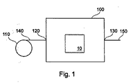
[0012]図1は、本発明にしたがったウェブガイドコントロール10が具現化されているウェブ処理装置の一実施形態を示している。ウェブ処理装置はウェブ処理ユニット100を備えており、ここでウェブ140が供給される。さらに、ウェブ保存ユニット110が示されており、ここではウェブ140がコイル状にされている。ウェブ140は入口ポート120を介してウェブ処理ユニット100に入る。処理済みウェブ150は出口ポート130を介してウェブ処理ユニット100から外にガイドされる。とりわけ周囲圧力では、上記のような入口または出口ポート、あるいは他のユニットを使用しない設備もある。一般的に、ウェブ処理ユニット100は、シリアルウェブ処理のために、本発明にしたがった1つ、2つ、3つまたはこれ以上のウェブガイドコントロールを備えている。本出願で使用されている用語「ウェブ」の同義語はストリップや柔軟性基板などである。
[0012] FIG. 1 illustrates one embodiment of a web processing apparatus in which a
[0013]一般的に、ウェブは3次元の固体であり、この厚さは最大1mm、より一般的には1μm〜500μmの範囲であり、またこの幅は、10cm〜4.5m、より一般的には30cm〜3mである。一般的な実施形態では、ウェブの長さは10mより長い。一般的に、ウェブは、薄くて柔軟性のある材料の連続シートからなる。一般的なウェブ材料は、金属、プラスチック、紙などである。 [0013] Generally, the web is a three-dimensional solid, the thickness of which is up to 1 mm, more typically in the range of 1 μm to 500 μm, and the width is 10 cm to 4.5 m, more commonly Is 30 cm to 3 m. In a typical embodiment, the web length is greater than 10 meters. In general, the web consists of a continuous sheet of thin and flexible material. Common web materials are metal, plastic, paper and the like.
[0014]本発明の一実施形態によると、ウェブ140はウェブサプライからウェブ処理ユニット100に供給される。一般的に、ウェブサプライはウェブ保存ユニット110であり、ここでウェブはコイル状にされている。コイル上のウェブの一般的な長さは500m〜50kmの範囲である。他の実施形態では、ウェブサプライは、例えば、ウェブ処理ユニット100(図示せず)に供給されるためにウェブがセクションを出る出口ポートを具備するか具備しないセクションから連続している。一般的なガイド速度は0.1〜20メートル毎秒の範囲である。一般的に、ウェブ処理ユニット100においては、ウェブのクリーニング、コーティング、冷却、加熱または構築などの異なる処理ステップが実行される。
[0014] According to one embodiment of the invention, the
[0015]ウェブ処理ユニット100においてウェブが処理された後、処理済みウェブ150は、出口ポート130でウェブ処理ユニット100を出る。一般的に、処理済みウェブ150は第2の処理ユニットに供給されたり、外にガイドされて保存されたりする。
[0015] After the web is processed in the
[0016]一般的に、本発明にしたがった1つ以上のウェブガイドコントロールを備えるウェブ処理装置が、種々の用途においてウェブをガイドするために使用可能である。このウェブ処理装置は、金属ウェブ、とりわけアルミニウムウェブ、および薄いプラスチックウェブなどの難しいウェブにとりわけ適している。この点で薄いウェブとは、1μm〜200μm、とりわけ30μm〜140μmの厚さを有するものと理解されるべきである。 [0016] Generally, a web processing device with one or more web guide controls according to the present invention can be used to guide the web in a variety of applications. This web processing apparatus is particularly suitable for difficult webs such as metal webs, especially aluminum webs, and thin plastic webs. A thin web in this respect should be understood as having a thickness of 1 μm to 200 μm, in particular 30 μm to 140 μm.
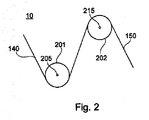
[0017]図2は、本発明のウェブガイドコントロール10の一実施形態の断面図を示している。ウェブガイドコントロール10は、対応するシャフト軸205を具備する第1のガイドローラ201と、対応するシャフト軸215を具備する第2のガイドローラ202とを備えている。ウェブ140は第1のガイドローラ201および第2のガイドローラ202を介してガイドされる。ウェブ140は未処理であるか、1つ以上の処理ステップをすでに経ていることもある。一般的に、第1のガイドローラ201は第2のガイドローラ202の上流に位置決めされている。本出願における用語「下流」および「上流」は、ウェブの移動方向に対して理解されるべきである。本発明のウェブガイドコントロール10は、ウェブ処理装置における具現化に制限されるわけではない。例えば、ウェブガイドコントロールは、移送が必要とされるプラントを製造する際にも具現化可能である。原則として、第2のガイドローラ202の下流にガイドローラ201を位置決めすることも可能である。
[0017] FIG. 2 illustrates a cross-sectional view of one embodiment of the
[0018]本発明によると、両シャフト軸205と215間の距離は、両ガイドローラ201および202間を移動するウェブに作用する横方向の張力を補償するように調整可能である。補償を可能にするために、第2のガイドローラには、張力センサなどのウェブ張力測定ユニットが装備される。張力センサは、ピエゾ抵抗または圧電張力センサであってもよい。代替的に、このセンサには、張力を判断するためにホール素子やコンデンサが装備されてもよい。他の実施形態では、第1のガイドローラおよび第2のガイドローラの両方とも張力測定ユニットが装備されている。図面に示されている本発明の一実施形態によると、ウェブ張力測定ユニットは第2のガイドローラ202で囲まれている。一般的に、測定センサは、0〜400N/mの張力を測定するようになっている。一般的に、この距離は、第1のガイドローラ201の一方の側部に置かれた調整ユニットを使用して調整される。ローラの「側部」とは、ローラまたはこの軸の端部における、またはこれに近接する位置として理解されるべきである。本発明で使用されているガイドローラの一般的な直径は65mm〜300mmである。
[0018] According to the present invention, the distance between both
[0019]シングルローラシステムではなく、測定および調整に2ローラシステムを使用することの利点は、例えば、コントロールループによってもたらされる振動のより良好な取り扱いである。 [0019] An advantage of using a two-roller system for measurement and adjustment rather than a single-roller system is, for example, better handling of vibrations caused by the control loop.
[0020]原則として、調整ユニットは、ウェブに作用する横方向の張力を回避するために必要なガイドローラの整列に適用されてもよい。一般的に、本発明のウェブガイドコントロール10は、ガイドローラ201および202における異なるコイリング強度を補償するのにとりわけ有用である。異なるコイリング強度は、ウェブの幅に沿った異なる厚さの、もっとも一般的な結果である。これは傾斜供給、ひいては、熱的な問題に付随する恐れのある、ガイドローラとウェブ間の様々な接触をもたらしうる。隣接するガイドローラの軸間の1m未満の、一般的により短い距離は、ウェブの適切な取り扱いについてより重要である。
[0020] In principle, the adjustment unit may be applied to the alignment of the guide rollers necessary to avoid the lateral tension acting on the web. In general, the
[0021]本発明の一部の実施形態では、第1のガイドローラ201および/または第2のガイドローラ202は冷却または加熱ローラである。代替的または付加的に、第1のガイドローラ201と第2のガイドローラ202との間、第1のガイドローラ201および第2のガイドローラ202の上流、または第1ガイドローラおよび第2のガイドローラの下流にさらなる冷却または加熱ガイドローラが位置決めされてもよい。クリーニングやコーティングなどの他の処理ステップが、第1のガイドローラの前、第1のガイドローラと第2のガイドローラの間、または第2のガイドローラの後で行われてもよい。
[0021] In some embodiments of the present invention, the
[0022]図3は、本発明の一般的な実施形態の平面図を示している。横方向のウェブ張力の調整の一部を形成する本実施形態の異なる要素が図面に示されている。すなわち、第1のガイドローラ201における調整ユニット310、第2のガイドローラ202におけるウェブ張力測定ユニット300、および調整ユニット310に張力データを供給するための、両ガイドローラ201と202間のデータコネクション330。一般的に、第1のガイドローラ201は第2のガイドローラ202の上流に位置決めされる。
[0022] FIG. 3 shows a plan view of a general embodiment of the present invention. The different elements of this embodiment that form part of the adjustment of the transverse web tension are shown in the drawing. That is, the
[0023]データコネクション330は、測定ユニットから調整ユニット310に情報を送信するために使用される。データコネクション330は、調整ユニット310から外部インタフェースに情報を送信するためにも使用可能である。一般的に、このインタフェースは、調整ユニット310からのデータを処理するパーソナルコンピュータからなる。このインタフェースもまた、調整ユニット310をチューニングするために異なる要素を備えており、例えば、異なる電位差計、ダイアル、スイッチおよびディスプレイを使用するアナログフロントパネルからなってもよい。さらに、このインタフェースはまた、数字パッド、グラフィカルディスプレイ、テキストコマンドまたはグラフィカルユーザーインタフェースを含むディジタルデバイスからなってもよい。一般的に、これらのインタフェースすべては、コントローラ関数、システムの較正、周囲条件の補償、あるいは張力ユニット300または調整ユニット310からの波形の取得および記録などの異なる特徴を含む。
[0023] The
[0024]異なるデバイスにデータコネクション330を接続するために、異なるポートタイプが使用される。一般的に、シリアル通信が使用される場合、ポートはRS232、RS422、RS485またはユニバーサルシリアルバス(USB)ポートである。一般的に、パラレル通信デバイスは、データコネクション330とコンピュータ間の通信が必要な場合に使用される。もっとも頻繁に使用されるパラレル通信デバイスはDB−25、Centronics36、SPP、EPPまたはECPパラレルポートである。データコネクション330は、調整ユニット310をトランジスタ・トランジスタ論理回路(TTL)やプログラマブル論理コントローラ(PLC)と互換性をもたせるために使用可能である。付加的に、データコネクション330は、調整ユニット310とネットワークを接続するために使用可能である。
[0024] Different port types are used to connect the
[0025]本発明の一実施形態によると、第2のガイドローラ202の両シャフト軸215および216に作用する張力は個別に取得される。取得されたデータは、第1のガイドローラ201において処理されて、調整ユニット310に送られる。調整ユニット310は、第1のガイドローラ201の一方の側部でシャフト軸の位置を調整する。これによって、第1のガイドローラのシャフト軸と第2のガイドローラのシャフト軸との間の距離が調整される。調整ユニット300は、第2のガイドローラ202の両側部のシャフト軸間で測定された張力を等しくするために操作される。しかしながら、第1のガイドローラ201(図示せず)の両側部のシャフト軸の位置を調整することも可能である。
[0025] According to one embodiment of the present invention, the tension acting on both
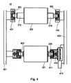
[0026]図4は、調整ユニットが回転シャフト軸420および変換要素411からなる本発明のウェブガイドコントロール10の別の実施形態の平面図を示している。ウェブ張力測定ユニット300は第2のガイドローラ202のベアリング431および432に置かれる。一般的に、変換要素411は、モータ、およびマシーンフレーム452に沿って変位可能な移動ベアリング415等のドライブ410を囲んでいる。シャフト軸206は、ドライブ410を囲む移動ベアリング415に取り付けられる。回転シャフト軸420は、マシーンフレーム451に対して回転自由度をもって取り付けられているシャフト軸205を囲んでいる。
FIG. 4 shows a plan view of another embodiment of the
[0027]異なる種類のモータが、本発明の調整ユニットで使用可能である。第1のガイドローラ201において、2つのガイドローラ201および202のベアリング間の距離は一方の側部で調整可能である。こうするために、駆動エンジンが一般的に使用される。一般的に、調整用ドライブは、本発明にしたがった電気または油圧いずれかのモータである。第1のガイドローラ201の移動ベアリング415の位置は、第2のガイドローラ202における両張力測定センサが同一ローディングに面するように調整される。
[0027] Different types of motors can be used in the adjustment unit of the present invention. In the
[0028]本発明の一般的な実施形態では、ウェブ張力測定ユニットはトランスデューサおよび歪みゲージからなる。一般的に、トランスデューサは、様々な張力に応答して伸長または圧縮するビームからなる。歪みゲージは、対応する電気抵抗の変化を測定する。一般的に、歪みゲージによって実行される測定は増幅されて、さらなる処理の電圧または電流に変換される。概して、ウェブ張力測定ユニットは、張力測定のさらなる処理のために、アナログまたはディジタルのフロントエンドを囲んでいる。一般的に、ウェブ張力測定ユニットは、第1および第2のガイドローラ間のウェブの移動方向の張力の測定を最大化するように整列される。一般的に、ウェブ張力測定ユニットは、異なるオプションを使用するガイドローラにおいて、つまり軸受(pillow blocks)間に、カンチレバーブラケットを使用して、フランジまたはクランプによる固定を使用して、スタッドを使用して、あるいはスルーホールにネジ切りされて搭載される。 [0028] In a general embodiment of the invention, the web tension measuring unit consists of a transducer and a strain gauge. In general, a transducer consists of a beam that expands or compresses in response to various tensions. A strain gauge measures the corresponding change in electrical resistance. In general, the measurement performed by the strain gauge is amplified and converted into a voltage or current for further processing. In general, the web tension measurement unit surrounds an analog or digital front end for further processing of tension measurements. Generally, the web tension measurement unit is aligned to maximize the measurement of the tension in the direction of web movement between the first and second guide rollers. In general, web tension measuring units use studs on guide rollers using different options, i.e., between cantilever brackets, using cantilever brackets, using flanges or clamping. Or, it is threaded into the through hole.
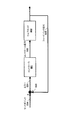
[0029]図5は、本発明の一実施形態にしたがったウェブガイドコントロールシステムの信号フローチャートを示しており、これは、横方向の張力測定のネガティブフィードバック500に基づいた閉ループコントローラを含んでいる。閉ループシステムは、コントローラ自体の出力である被コントロールシステムに供給されたフィードバック信号533およびコントロール信号532の先の値を使用することによって、セットポイント534の値に等しい被コントロールシステムの出力、例えばフィードバック信号533を維持する。フローチャートの主要要素は、本発明にしたがったウェブガイドコントロール10を構成するコントローラ501およびウェブガイドシステム502である。第2のガイドローラ202の両側部の張力差はフィードバック信号533である。一般的に、本発明のコントローラのセットポイント534は、ウェブに作用する横方向の張力に対応する張力差を補償するために中立(null)値を有する。したがって、本発明の一般的な実施形態では、コントローラの誤差531は、張力差測定値、つまりフィードバック信号533に正確に対応する。本発明の一般的な実施形態では、コントローラは、調整ユニット310を使用して誤差531のゼロからの偏差を補償する。一般的に、この誤差531の補償は、両ガイドローラ201および202の一方の側部のシャフト軸205および215の距離調整に変換する。したがって、コントロール信号532、例えばコントローラ出力は一般的に、両ガイドローラ201および202の一方の側部のシャフト軸間の距離に対応する。
[0029] FIG. 5 shows a signal flow chart of a web guide control system according to an embodiment of the present invention, which includes a closed loop controller based on a
[0030]原則として、異なるコントロールアプローチがコントローラ501で具現化可能である。一般的に、比例・積分・微分(PID)コントロール、比例・積分(PI)コントロール、比例・微分(PD)コントロールおよび比例(P)コントロールから選択する線形コントロールアプローチがコントローラ501で具現化される。しかしながら、例えば適応利得、不感時間補償、ファジー論理、神経ネットワークまたはフィードフォワードコントロールなどの非線形コントロールアプローチを使用する他の高度コントロールも本発明の実施形態で具現化可能である。本出願で具現化されたコントローラは、トランジスタ・トランジスタ論理回路(TTL)との互換性を含むアナログまたはディジタルインタフェースであってもよい。一般的に、ディジタルインタフェースは、一定の固定期間Δt後に調整ユニットの値がリフレッシュされる離散的な方法で動作する。他の特殊な特徴は、セルフチューニング、信号算出またはフィルタリング、あるいはビルトインインジケーターなどの本発明のコントローラに見ることができる。
[0030] In principle, different control approaches can be implemented in the
[0031]本発明の実施形態にしたがったコントローラの機能の図示として、以下、離散PIDコントローラの具現化が説明される。所与のコントロールステップiのフィードバック信号は、両張力測定値Ti 215とTi 216の差に対応する。一般的に、本発明に対応する実施形態について、コントローラは、ウェブに作用する横方向の力を補償すべきであるため、つまり第2のガイドローラ202の両側部の張力が等しくあるべきであるため、セットポイントはゼロに保たれる。したがって、所与の処理ステップiの誤差信号は、
Ei=Ti 215−Ti 216
に対応する。PIDコントローラは、
Di+1=Di+KpEi+Kd(Ei−Ei−1)
を使用して出力値Di+1を算出する。ここで、第1の項はコントローラの積分部分に対応し、第2の項は比例部分に対応し、第3の項は微分部分に対応する。Kpは比例バンドであり、Kdは微分利得である。一般的に、ゼロ以外のDi+1−Diの値は、第1のガイドローラ201の一方の側部の位置の変動に対応する。本発明の他の実施形態では、これは、第1のガイドローラ201の調整ユニットにおいてドライブ410を操作する信号に対応する。
[0031] As an illustration of the functionality of a controller according to an embodiment of the present invention, the implementation of a discrete PID controller is described below. The feedback signal for a given control step i corresponds to the difference between both tension measurements T i 215 and T i 216 . In general, for embodiments corresponding to the present invention, the controller should compensate for the lateral forces acting on the web, that is, the tension on both sides of the
E i = T i 215 −T i 216
Corresponding to PID controller
D i + 1 = D i + K p E i + K d (E i −E i−1 )
Is used to calculate the output value D i + 1 . Here, the first term corresponds to the integral part of the controller, the second term corresponds to the proportional part, and the third term corresponds to the derivative part. K p is a proportional band, K d is a differential gain. In general, a value of D i + 1 −D i other than zero corresponds to a change in the position of one side of the
[0032]ここに記された説明は実施例を使用して、最良の形態を含む本発明を開示し、当業者が本発明を為し、かつこれを使用できるようにする。本発明は種々の特定の実施形態に関して説明されてきたが、当業者は、本発明が、請求項の趣旨および範囲内の修正によって実践可能であることを認識するであろう。特に、上記実施形態の非制限的特徴は相互に組み合わせ可能である。本発明の特許可能な範囲は請求項によって定義されており、また当業者が想起する他の実施例を含んでもよい。このような他の実施例は、請求項の文言と違わない構造的要素を有する場合、あるいは請求項の文言とはわずかな差があるが等価的な構造的要素を含む場合に、特許請求の範囲内にあるとするものである。 [0032] The description set forth herein uses examples to disclose the invention, including the best mode, and also to enable any person skilled in the art to make and use the invention. While the invention has been described in terms of various specific embodiments, those skilled in the art will recognize that the invention can be practiced with modification within the spirit and scope of the claims. In particular, the non-limiting features of the above embodiments can be combined with each other. The patentable scope of the invention is defined by the claims, and may include other examples that occur to those skilled in the art. Such other embodiments may have structural elements that do not differ from the claim language, or include equivalent structural elements that differ slightly from the claim language. It is assumed to be within the range.
Claims (16)
前記第1のガイドローラが調整ユニット(310)を備え、
前記第2のガイドローラが張力測定ユニット(300)を備え、
前記ウェブガイドコントロールが、前記張力測定ユニットからの張力データによって前記調整ユニットをサポートするためのデータコネクション(330)を備えるウェブガイドコントロール。 A web guide control for guiding a web, the web guide control having a first guide roller (201) and a second guide roller (202),
The first guide roller comprises an adjustment unit (310);
The second guide roller comprises a tension measuring unit (300);
A web guide control, wherein the web guide control comprises a data connection (330) for supporting the adjustment unit by means of tension data from the tension measuring unit.
第2のガイドローラに作用する前記ウェブの張力を測定して、測定結果を受け取るステップと、
を備えており、
調整ステップが前記測定結果に基づく、ウェブガイド方法。 Adjusting the position of the first guide roller by moving one side of the first guide roller;
Measuring the tension of the web acting on the second guide roller and receiving the measurement results;
With
A web guiding method, wherein the adjusting step is based on the measurement result.
Applications Claiming Priority (3)
| Application Number | Priority Date | Filing Date | Title |
|---|---|---|---|
| US89210207P | 2007-02-28 | 2007-02-28 | |
| EP07004189A EP1964799B1 (en) | 2007-02-28 | 2007-02-28 | Web guide control, web processing apparatus and method for operating the same |
| PCT/EP2008/052438 WO2008104593A1 (en) | 2007-02-28 | 2008-02-28 | Web guide control, web processing apparatus and method for operating the same |
Publications (2)
| Publication Number | Publication Date |
|---|---|
| JP2010520131A true JP2010520131A (en) | 2010-06-10 |
| JP2010520131A5 JP2010520131A5 (en) | 2011-04-21 |
Family
ID=38267575
Family Applications (1)
| Application Number | Title | Priority Date | Filing Date |
|---|---|---|---|
| JP2009551934A Pending JP2010520131A (en) | 2007-02-28 | 2008-02-28 | Web guide control, web processing apparatus, and operation method thereof |
Country Status (8)
| Country | Link |
|---|---|
| US (1) | US20100038468A1 (en) |
| EP (1) | EP1964799B1 (en) |
| JP (1) | JP2010520131A (en) |
| KR (1) | KR20090115971A (en) |
| AT (1) | ATE465112T1 (en) |
| DE (1) | DE602007005973D1 (en) |
| TW (1) | TWI379016B (en) |
| WO (1) | WO2008104593A1 (en) |
Cited By (4)
| Publication number | Priority date | Publication date | Assignee | Title |
|---|---|---|---|---|
| JP2013249505A (en) * | 2012-05-31 | 2013-12-12 | Sony Corp | Film-forming apparatus and film-forming method |
| JP2016008326A (en) * | 2014-06-25 | 2016-01-18 | 東レエンジニアリング株式会社 | Substrate transferring and processing apparatus |
| JP2016508935A (en) * | 2013-01-31 | 2016-03-24 | アプライド マテリアルズ インコーポレイテッドApplied Materials,Incorporated | Web guide control unit, web processing apparatus and method for operating them |
| JP2018149065A (en) * | 2017-03-13 | 2018-09-27 | 王子ホールディングス株式会社 | Tension adjusting device and tension adjusting method used in absorbent article manufacturing apparatus |
Families Citing this family (10)
| Publication number | Priority date | Publication date | Assignee | Title |
|---|---|---|---|---|
| US8554354B1 (en) * | 2010-02-12 | 2013-10-08 | The Board Of Regents For Oklahoma State University | Method for adaptive guiding of webs |
| JP5880808B2 (en) * | 2011-04-21 | 2016-03-09 | 東洋製罐株式会社 | Bag making equipment |
| JP5992743B2 (en) * | 2012-07-12 | 2016-09-14 | 津田駒工業株式会社 | Prepreg sheet feeder |
| KR102083960B1 (en) * | 2012-08-30 | 2020-03-03 | 엘지전자 주식회사 | Method for manufacturing graphene and the graphene manufactured by the same and the manufacturing apparatus |
| WO2016208022A1 (en) * | 2015-06-25 | 2016-12-29 | 株式会社ニレコ | Web meandering control device and control method |
| CN106601390B (en) * | 2016-12-30 | 2017-12-19 | 嵊州北航投星空众创科技有限公司 | A kind of capacitor core coiler device with mobile tension regulating function |
| CN106847499B (en) * | 2016-12-30 | 2018-06-08 | 郑州大学综合设计研究院有限公司 | A kind of capacitor core coiler device |
| US20220002107A1 (en) * | 2020-07-01 | 2022-01-06 | CSG Holding, Inc. | Webtension transducer load cell with integrated data interface |
| CN117279849A (en) * | 2021-05-06 | 2023-12-22 | 应用材料公司 | Cross web tension measurement and control |
| CN113258240B (en) * | 2021-05-19 | 2021-12-28 | 东南大学 | A nonlinear artificial SPP waveguide for parametric amplification of multi-frequency signal waves and its calculation method |
Citations (3)
| Publication number | Priority date | Publication date | Assignee | Title |
|---|---|---|---|---|
| JPH0361248A (en) * | 1989-07-31 | 1991-03-18 | Toshiba Chem Corp | Left and right tension compensating apparatus for long-length film |
| JPH09169108A (en) * | 1995-08-30 | 1997-06-30 | Rockwell Internatl Corp | Tension adjusting device for printing press |
| JP2006326945A (en) * | 2005-05-24 | 2006-12-07 | Matsushita Electric Works Ltd | Prepreg manufacturing apparatus and manufacturing method |
Family Cites Families (9)
| Publication number | Priority date | Publication date | Assignee | Title |
|---|---|---|---|---|
| US4347993A (en) * | 1979-11-06 | 1982-09-07 | W. J. Industries, Incorporated | Tension monitor means and system |
| DE9108408U1 (en) * | 1991-07-08 | 1991-08-29 | H. Krantz Textiltechnik GmbH, 52070 Aachen | Device for eliminating skew distortions in a running web |
| CA2074434C (en) * | 1992-07-22 | 1997-04-15 | Yasuo Ichii | Strip tension control apparatus |
| US5419509A (en) * | 1993-05-12 | 1995-05-30 | Krayenhagen; Everett D. | Web tensioning device for automatic cross-machine tensioning of continuous webs |
| US6659006B2 (en) * | 1995-08-30 | 2003-12-09 | Goss Graphic Systems Inc. | Tension control device for a printing press |
| DE19960649B4 (en) * | 1999-12-16 | 2011-06-22 | Goss Contiweb B.V. | Device for correcting the lateral position of a printing material web in a web-fed rotary printing press |
| US6547707B2 (en) * | 2001-01-10 | 2003-04-15 | Heidelberger Druckmaschinen Ag | Strain control in an infeed of a printing machine |
| US6659323B2 (en) * | 2002-01-30 | 2003-12-09 | Presstek, Inc. | Methods and apparatus for prescribing web tracking in processing equipment |
| US7438251B2 (en) * | 2003-06-19 | 2008-10-21 | Specialty Systems Advanced Machinery, Inc. | Web tensioning device with plural control inputs |
-
2007
- 2007-02-28 DE DE602007005973T patent/DE602007005973D1/en active Active
- 2007-02-28 EP EP07004189A patent/EP1964799B1/en not_active Not-in-force
- 2007-02-28 AT AT07004189T patent/ATE465112T1/en not_active IP Right Cessation
-
2008
- 2008-02-26 TW TW097106673A patent/TWI379016B/en not_active IP Right Cessation
- 2008-02-28 US US12/528,789 patent/US20100038468A1/en not_active Abandoned
- 2008-02-28 JP JP2009551934A patent/JP2010520131A/en active Pending
- 2008-02-28 KR KR1020097020108A patent/KR20090115971A/en not_active Withdrawn
- 2008-02-28 WO PCT/EP2008/052438 patent/WO2008104593A1/en not_active Ceased
Patent Citations (3)
| Publication number | Priority date | Publication date | Assignee | Title |
|---|---|---|---|---|
| JPH0361248A (en) * | 1989-07-31 | 1991-03-18 | Toshiba Chem Corp | Left and right tension compensating apparatus for long-length film |
| JPH09169108A (en) * | 1995-08-30 | 1997-06-30 | Rockwell Internatl Corp | Tension adjusting device for printing press |
| JP2006326945A (en) * | 2005-05-24 | 2006-12-07 | Matsushita Electric Works Ltd | Prepreg manufacturing apparatus and manufacturing method |
Cited By (4)
| Publication number | Priority date | Publication date | Assignee | Title |
|---|---|---|---|---|
| JP2013249505A (en) * | 2012-05-31 | 2013-12-12 | Sony Corp | Film-forming apparatus and film-forming method |
| JP2016508935A (en) * | 2013-01-31 | 2016-03-24 | アプライド マテリアルズ インコーポレイテッドApplied Materials,Incorporated | Web guide control unit, web processing apparatus and method for operating them |
| JP2016008326A (en) * | 2014-06-25 | 2016-01-18 | 東レエンジニアリング株式会社 | Substrate transferring and processing apparatus |
| JP2018149065A (en) * | 2017-03-13 | 2018-09-27 | 王子ホールディングス株式会社 | Tension adjusting device and tension adjusting method used in absorbent article manufacturing apparatus |
Also Published As
| Publication number | Publication date |
|---|---|
| EP1964799B1 (en) | 2010-04-21 |
| EP1964799A1 (en) | 2008-09-03 |
| ATE465112T1 (en) | 2010-05-15 |
| US20100038468A1 (en) | 2010-02-18 |
| TWI379016B (en) | 2012-12-11 |
| DE602007005973D1 (en) | 2010-06-02 |
| WO2008104593A1 (en) | 2008-09-04 |
| KR20090115971A (en) | 2009-11-10 |
| TW200848539A (en) | 2008-12-16 |
Similar Documents
| Publication | Publication Date | Title |
|---|---|---|
| JP2010520131A (en) | Web guide control, web processing apparatus, and operation method thereof | |
| US8584489B2 (en) | Non-contact dancer mechanisms, web isolation apparatuses and methods for using the same | |
| US4775086A (en) | Take-out/take-up tension control apparatus | |
| US4708301A (en) | Take-out/take-up tension control apparatus | |
| WO2009122836A1 (en) | Production equipment and method of thin-film laminate | |
| EP0681510A4 (en) | Strip coating machine with thickness control. | |
| WO2021140747A1 (en) | Roll press device, and control device | |
| CN104955751B (en) | Web guiding control unit, web handling device and method of operation thereof | |
| CN114945432B (en) | Rolling device and control device | |
| JPH07108551A (en) | Automatic thickness control device for calendar device | |
| CN113353701B (en) | Polyester optical film winding system | |
| JP3255242B2 (en) | Method and apparatus for controlling sheet thickness in calendar | |
| CN119114645B (en) | AI-based dry electrode forming control method and integrated electrode forming machine | |
| CN120817483A (en) | Accurate contact pressure control device and control method for lithium battery diaphragm dividing and cutting machine | |
| KR810001346B1 (en) | Winding tension control method | |
| JPH05116824A (en) | Tension control device for sheet-like material | |
| JPS6137652A (en) | Winding tensile controller | |
| US20240002185A1 (en) | Electronic Nip Adjustment and Pressure Measurement on Pull Station | |
| CN119976497A (en) | A winding tension control system | |
| TW202320194A (en) | Cross web tension measurement and control | |
| CN119114645A (en) | Dry-process pole piece forming control method based on AI algorithm and pole piece forming composite integrated machine | |
| JENTZEN et al. | 8.36 Rolling Mill Controls | |
| JPS61169439A (en) | Slitter winder |
Legal Events
| Date | Code | Title | Description |
|---|---|---|---|
| RD03 | Notification of appointment of power of attorney |
Free format text: JAPANESE INTERMEDIATE CODE: A7423 Effective date: 20101130 |
|
| RD04 | Notification of resignation of power of attorney |
Free format text: JAPANESE INTERMEDIATE CODE: A7424 Effective date: 20101210 |
|
| A521 | Request for written amendment filed |
Free format text: JAPANESE INTERMEDIATE CODE: A523 Effective date: 20110217 |
|
| A621 | Written request for application examination |
Free format text: JAPANESE INTERMEDIATE CODE: A621 Effective date: 20110217 |
|
| A977 | Report on retrieval |
Free format text: JAPANESE INTERMEDIATE CODE: A971007 Effective date: 20120531 |
|
| A131 | Notification of reasons for refusal |
Free format text: JAPANESE INTERMEDIATE CODE: A131 Effective date: 20120612 |
|
| A521 | Request for written amendment filed |
Free format text: JAPANESE INTERMEDIATE CODE: A523 Effective date: 20120910 |
|
| RD04 | Notification of resignation of power of attorney |
Free format text: JAPANESE INTERMEDIATE CODE: A7424 Effective date: 20120925 |
|
| A02 | Decision of refusal |
Free format text: JAPANESE INTERMEDIATE CODE: A02 Effective date: 20130122 |